EP3673760A1 - Ver- und entriegelungsvorrichtung für einen sportschuh - Google Patents
Ver- und entriegelungsvorrichtung für einen sportschuh Download PDFInfo
- Publication number
- EP3673760A1 EP3673760A1 EP18425106.4A EP18425106A EP3673760A1 EP 3673760 A1 EP3673760 A1 EP 3673760A1 EP 18425106 A EP18425106 A EP 18425106A EP 3673760 A1 EP3673760 A1 EP 3673760A1
- Authority
- EP
- European Patent Office
- Prior art keywords
- locking
- rear deflector
- unlocking device
- collar
- lever
- Prior art date
- Legal status (The legal status is an assumption and is not a legal conclusion. Google has not performed a legal analysis and makes no representation as to the accuracy of the status listed.)
- Pending
Links
- 230000000903 blocking effect Effects 0.000 claims abstract description 5
- 230000033001 locomotion Effects 0.000 claims description 19
- 230000006835 compression Effects 0.000 claims description 4
- 238000007906 compression Methods 0.000 claims description 4
- 230000000694 effects Effects 0.000 claims description 3
- 235000005921 Cynara humilis Nutrition 0.000 description 10
- 240000002228 Cynara humilis Species 0.000 description 10
- 210000002683 foot Anatomy 0.000 description 10
- 210000003423 ankle Anatomy 0.000 description 9
- 229910000831 Steel Inorganic materials 0.000 description 4
- 238000006073 displacement reaction Methods 0.000 description 4
- 239000010959 steel Substances 0.000 description 4
- 210000000544 articulatio talocruralis Anatomy 0.000 description 3
- 244000309466 calf Species 0.000 description 3
- 238000004519 manufacturing process Methods 0.000 description 3
- 238000013016 damping Methods 0.000 description 2
- 238000007373 indentation Methods 0.000 description 2
- 239000000725 suspension Substances 0.000 description 2
- 238000013519 translation Methods 0.000 description 2
- 238000004804 winding Methods 0.000 description 2
- 241000287107 Passer Species 0.000 description 1
- 238000013459 approach Methods 0.000 description 1
- 230000005540 biological transmission Effects 0.000 description 1
- 230000000295 complement effect Effects 0.000 description 1
- 238000010276 construction Methods 0.000 description 1
- 238000013461 design Methods 0.000 description 1
- 230000001939 inductive effect Effects 0.000 description 1
- 238000002347 injection Methods 0.000 description 1
- 239000007924 injection Substances 0.000 description 1
- 238000003780 insertion Methods 0.000 description 1
- 230000037431 insertion Effects 0.000 description 1
- 238000012423 maintenance Methods 0.000 description 1
- 239000000463 material Substances 0.000 description 1
- 238000007789 sealing Methods 0.000 description 1
- 239000000243 solution Substances 0.000 description 1
- 230000001360 synchronised effect Effects 0.000 description 1
- 239000004753 textile Substances 0.000 description 1
Images


Classifications
-
- A—HUMAN NECESSITIES
- A43—FOOTWEAR
- A43B—CHARACTERISTIC FEATURES OF FOOTWEAR; PARTS OF FOOTWEAR
- A43B5/00—Footwear for sporting purposes
- A43B5/04—Ski or like boots
- A43B5/0427—Ski or like boots characterised by type or construction details
-
- A—HUMAN NECESSITIES
- A43—FOOTWEAR
- A43B—CHARACTERISTIC FEATURES OF FOOTWEAR; PARTS OF FOOTWEAR
- A43B5/00—Footwear for sporting purposes
- A43B5/04—Ski or like boots
- A43B5/0427—Ski or like boots characterised by type or construction details
- A43B5/047—Ski or like boots characterised by type or construction details provided with means to improve walking with the skiboot
- A43B5/0474—Ski or like boots characterised by type or construction details provided with means to improve walking with the skiboot having a walk/ski position
-
- A—HUMAN NECESSITIES
- A43—FOOTWEAR
- A43B—CHARACTERISTIC FEATURES OF FOOTWEAR; PARTS OF FOOTWEAR
- A43B5/00—Footwear for sporting purposes
- A43B5/04—Ski or like boots
- A43B5/0427—Ski or like boots characterised by type or construction details
- A43B5/0452—Adjustment of the forward inclination of the boot leg
- A43B5/0454—Adjustment of the forward inclination of the boot leg including flex control; Dampening means
- A43B5/0456—Adjustment of the forward inclination of the boot leg including flex control; Dampening means with the actuator being disposed at the rear side of the boot
-
- A—HUMAN NECESSITIES
- A43—FOOTWEAR
- A43B—CHARACTERISTIC FEATURES OF FOOTWEAR; PARTS OF FOOTWEAR
- A43B5/00—Footwear for sporting purposes
- A43B5/04—Ski or like boots
- A43B5/0427—Ski or like boots characterised by type or construction details
- A43B5/047—Ski or like boots characterised by type or construction details provided with means to improve walking with the skiboot
Definitions
- the invention relates to a locking and unlocking device for forming an interface between a shell bottom and a collar of a sports boot, in particular a ski boot, the collar being articulated in rotation around the shell bottom.
- the invention also relates to a sports boot, in particular a ski boot comprising such a locking and unlocking device.
- a locking and unlocking device In order to block or release the articulation between the bottom of the shell and the collar, the use of a locking and unlocking device is also known, also known in English terms as "ski-walk". These devices include a lever operable by hand and allowing to choose between two configurations of the shoe. The first configuration, called “ski”, blocks the articulation between the collar and the bottom of the hull. The second configuration, called “walk” or “walk”, frees the articulation between the collar and the bottom of the hull.
- the object of the invention is to provide a locking and unlocking device overcoming the above drawbacks and improving the locking and unlocking devices known from the prior art.
- the invention makes it possible to produce locking and unlocking devices which are simple to manufacture, reliable, robust, light, compact, and easy to handle.
- Another objective of the invention is to make it possible to achieve a walking configuration allowing a range of motion sufficient for the comfort of the user.
- the invention also relates to a sports boot as such, in particular a ski boot, comprising such a locking and unlocking device.
- a shoe is considered to rest via its sole on a horizontal floor.
- the X axis designates the longitudinal axis. In progression forward and in a straight line, a user of the shoe progresses from rear to front in a direction parallel to the longitudinal axis X.
- the axis X is oriented from rear to front .
- the Y axis designates the transverse axis of the user. The Y axis is oriented from left to right according to the user's point of view.
- the Z axis designates the axis perpendicular to the X axis and the Y axis.
- the Z axis is a vertical axis when the user is on horizontal ground.
- the Z axis is oriented from bottom to top.
- the X, Y and Z axes form an orthogonal coordinate system.
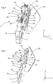
- the figure 1 partially illustrates a sports shoe 1 according to an embodiment of the invention.
- the sports boot is a ski boot particularly suitable for the practice of alpine skiing, ski touring, telemark, or even even the practice of snowboarding.
- the invention which will be described could be used for any type of sports shoe comprising an articulation and a removable locking means for this articulation.
- the ski boot 1 includes a shell bottom 2 able to wrap the foot below the ankle, and a collar 3 able to wrap the bottom of the leg above the ankle.
- the ski boot can also include a comfort boot (not shown) interposed between the bottom of the shell and the user's foot and between the collar and the user's foot, as well as tightening means (not shown). ) the collar around the bottom of the leg and / or the shell bottom around the foot.
- the shell bottom and the collar are each made of a wall, advantageously obtained by plastic injection.
- the ski boot 1 comprises a rotary joint 4 between the bottom of the shell 2 and the collar 3.
- the rotary joint 4 can be produced by means of bearings arranged in the bottom of the shell 2 and in the collar 3 These bearings are then positioned at the height of the internal malleolus and the external malleolus and cooperate with axes (not shown), such as screws or rivets.
- the axis A1 designates the axis of rotation of the collar around the bottom of the hull.
- the axis A1 is substantially parallel to the transverse axis Y.
- the ski boot 1 comprises a locking and unlocking device 5, particularly shown in the figure 3 , according to an embodiment of the invention.
- the locking and unlocking device 5 forms an interface between the bottom of the shell 2 and the collar 3. It makes it possible to block or release the articulation in rotation 4 between the bottom of the shell 2 and the collar 3.
- the locking device and unlocking 5 is positioned at the rear of the ski boot and takes place in a notch 6 in the bottom of the shell 2.
- the notch 6 is an opening made at the rear and in the upper part of the bottom of the shell. It can have a “V” shape or a “U” shape and is particularly visible on figures 2 , 6 and 12 .
- the locking and unlocking device 5 is fixed to the collar 3 and cooperates with the bottom of the shell 2 to block or release the articulation in rotation.
- the ski boot can therefore be found in two distinct configurations.
- a first configuration called the “ski” configuration
- the articulation in rotation between the bottom of the shell 2 and the collar 3 is blocked, and the transmission of the forces from the foot to the boot and to the ski is optimal.
- the articulation of his ankle is therefore blocked.
- a small amplitude in the ankle joint may remain due to the rigidity of the materials used for the manufacture of the ski boot.
- the articulation in rotation between the bottom of the shell 2 and the collar 3 is released, that is to say it is free, or in other words, not blocked.
- the range of motion of the ankle can nevertheless be limited by the front and rear stops of the ski boot, in particular between the bottom of the shell and the collar.
- the range of motion of the ankle inside the shoe in the running configuration may be less than the range of natural movement of the ankle. It is nevertheless greater than the range of motion of the ankle inside the boot in ski configuration.
- the ski boot 1 and its locking and unlocking device 5 in the ski configuration are illustrated on the figures 1 to 4 .
- Ski boot 1 and its device locking and unlocking 5 in run configuration are illustrated on the Figures 5 to 8 .
- the rocker 10 comprises a first end, oriented downwards, and a second end, oriented upwards.
- the first lower end is equipped with a hooking means 11 able to cooperate with the bottom of the shell when the rocker 10 is in the locked position.
- the bottom of the hull comprises at the rear and in the middle a groove 7 oriented transversely.
- This groove can form with the bottom of the shell 2 a one-piece assembly or else be an element fixed to the bottom of the shell.
- the groove 7 is an attached element fixed to the bottom of the shell by means of two cooperating inserts with two holes of corresponding shape in the bottom of the shell 2.
- the attachment means 11 is constituted by a protrusion extending substantially along the longitudinal axis.
- the protuberance takes place in the groove 7.
- the stop of the protuberance on an upper edge of the groove prevents the collar from pivoting forward.
- the stop of the protrusion on a lower edge of the groove prevents the collar from pivoting backwards.
- the attachment means 11 could be a recess or a groove, which cooperates with a protuberance of the bottom of the shell, thus preventing movements of the collar relative to the bottom of the shell.
- the second upper end of the rocker 10 is equipped with a first connecting means 12 to the torsion spring.
- the first connecting means 12 is formed by a transversely extending groove. This groove is substantially oriented upwards and receives a first end 31 of the torsion spring 30.
- the torsion spring 30 is always more or less constrained whatever the configuration of the ski boot.
- the first end 31 of the torsion spring remains in place in the groove without risk of escaping therefrom.
- the first end 31 of the spring can be fixed to the rocker could be made via a recess provided for this purpose at the end of the rocker.
- the means of connection 12 of the lever to the torsion spring could be arranged so that a larger part of the spring than its single end 31 cooperates with the lever 10.
- the lever 10 is movable between a locking position in which it blocks the rotation of the collar 3 relative to the bottom of the shell 2, and an unlocking position in which it releases the rotation of the collar 3 relative to the bottom of the shell 2.
- the locking position is illustrated in particular on the figure 4 and the unlocking position is illustrated in particular on the figure 8 .
- the hooking means 11 of the rocker 10 is released from the groove 6 of the bottom of the hull and is therefore no longer in contact with the bottom of the hull.
- the rocker is movable in rotation between its locked position and its unlocked position around a first axis of rotation 41 positioned between the first end and the second end.
- the first axis of rotation 41 is integral with the support 40 and extends parallel to the transverse axis Y.
- the first axis 41 is mounted in rotation on the support 40, itself fixed on the collar.
- the first axis 41 is therefore also mounted in rotation relative to the collar.
- the first axis 41 is closer to the second high end than to the first low end.
- the rocker 10 also comprises a protuberance, for example in the form of a tooth or an outer rim 13 serving to support a lower rim of the collar 3.
- the outer rim forms a protrusion extending longitudinally towards the rear and comprises a length of the order of magnitude of the thickness of the wall forming the collar.
- the lever 20 is a part, preferably in one piece, comprising a wheel 21 and a lever 22.
- the lever 22 constitutes a means of manual actuation of the device 5 for the user.
- the lever 20 is movable in rotation about a second axis of rotation 42, between a first position and a second position.
- the second axis of rotation 42 is integral with the support 40 and extends parallel to the transverse axis Y.
- the second axis 42 is mounted in rotation on the support 40, itself fixed on the collar.
- the second axis 42 is therefore also mounted in rotation relative to the collar.
- the second axis 42 also extends parallel to the first axis of rotation 41 of the lever 10.
- the first axis 41 and the second axis 42 are therefore positioned at a fixed distance from one another.
- the wheel 21 has the overall shape of a cylinder and the second axis of rotation 42 passes through the axis of revolution of this cylinder.
- the wheel 21 includes a second connecting means 23 cooperating with a second end 32 of the torsion spring.
- This second connecting means 23 is offset by relative to the axis of rotation of the wheel 21. According to the embodiment presented, it consists of a hole oriented transversely, and cooperating with the second end 32 of the spring 30.
- the wheel 21 also includes a third means link 24 cooperating with two link arms 60.
- the third link means 24 is formed by an axis oriented transversely and projecting from both sides of the wheel 21.
- the axis is eccentric relative to the center of the wheel 21 and is positioned substantially at the base of the handle 22.
- the two link arms 60 each comprise a circular hole 61 cooperating with this axis.
- the two link arms 60 could each have two protrusions or pins to cooperate with a recess / bore made in the wheel 21.
- the link arms 60 thus form a connection means between the lever 20 and the deflector 50, of which the operation will be detailed later.
- the wheel 21 may locally include a recess 25 making it possible in particular to avoid any interference from contact with the rear deflector during the rotation of the wheel 21, while reducing it.
- the handle 22 protrudes from the ski boot towards the rear.
- the lever 20 When the ski boot is in ski configuration, the lever 20 is in the first position and the lever 22 extends generally rearward and downward.
- the lever 20 When the ski boot is in the running configuration, the lever 20 is in the second position and the lever 22 extends generally backwards and upwards. Between the first position and the second position, the lever 20 can rotate around a quarter of a turn.
- the collar comprises an opening 8, at the rear, facing the lever 20 so that the lever is easily accessible.
- the joystick can be operated directly by hand or via the tip of a ski pole.
- the handle advantageously comprises an opening making it possible to block the tip of the ski pole.
- the opening can allow the passage of a strap, for example textile, facilitating the gripping of the lever by the user to actuate the device.
- the torsion spring 30, which could also be called a “pin spring”, comprises a set of turns 33 between the two ends 31, 32.
- the torsion spring 30 is an elastic means for torsion. It is designed to be stressed according to a torque parallel to the axis of turns.
- the turns are inscribed in a cylinder-shaped envelope whose axis of revolution is oriented transversely. Thus, the torsion spring is able to be biased according to a torque around an axis parallel to the transverse axis Y.
- the figure 9 illustrates in more detail the design of the spring.
- the set of turns 33 is broken down into two groups of turns 33A, 33B arranged transversely on either side of the first end 31.
- the torsion spring is produced from a single steel wire. The two ends of the steel wire are positioned at the second end 32 of the torsion spring, while the first end 31 of the torsion spring is formed by a middle part of the steel wire extending substantially transversely. According to a view in the longitudinal and vertical plane, the two ends 31, 32 of the torsion spring are arranged in a “V” shape with all of the turns 33 positioned at the tip of the “V”.
- the torsion spring can be stressed by tightening the two arms of the "V", that is to say by bringing the two ends 31, 32 closer to each other.
- the small free part between the two ends of the steel wire at the second end is positioned in the same longitudinal and vertical plane as the middle of the first end 31.
- the rocker 10, the lever 20 and the torsion spring 30 are arranged so that when the lever is in its first position, the rocker is in the locked position and when the lever is in its second position, the rocker is in the unlock position.
- the locking position and the unlocking position of the rocker are kept stable under the effect of the spring 30. That is to say that the torsion spring tends to keep the rocker in the position in which it is located.
- the second connecting means 23 to which the second end 32 of the torsion spring 30 is fixed describes a circular movement. According to this circular movement, the second end 32 of the torsion spring progressively approaches the first end 31, then reaches maximum approximation, then moves away from the first end 31.
- the rotation of the lever from the first position to the second position causes the torsion spring to be loaded by torsion in the winding direction of the turns, then to relax the torsion spring.
- the same loading phenomenon followed by detente occurs when the lever moves from the second position to the first position.
- the movement of the rocker is caused by a movement of the lever via the torsion spring.
- the force applied by the user to the lever is transmitted to the rocker via the torsion spring.
- the spring 30 is held only by its first end 31 connected to the rocker and by its second end 32 connected to the lever.
- the ends 32 of the spring are positioned in recesses or holes made in the rocker.
- the torsion spring is not in contact with other elements of the ski boot.
- the torsion spring 30 serves both to stabilize the locking and unlocking positions of the rocker, and at the same time to transmit a force on the lever to the rocker.
- the support 40 is an element of the locking and unlocking device 5 fixedly attached to the collar 3 and supporting various elements of the locking and unlocking device 5.
- the support 40 is interposed between the collar, which is behind it, and the rear deflector 50 which is in front, along the longitudinal axis.
- the locking and unlocking device 5 is therefore protected from the outside by the collar 3 and inside the shoe by the rear deflector 50.
- the support 40 is fixed to the collar 3 on the one hand via two circular holes 43 in top of the support through which can pass two screws or two rivets in engagement with the collar. On the other hand, it is fixed to the collar via the first axis 41.
- the first axis 41 not only serves as an axis of rotation for the rocker 10 but it also cooperates with two openings 9 arranged in the collar 3, as can be seen in particular on the figures 1 and 5 .
- the first axis of rotation 41 is fixed to the support 40 at a lower end of the support.
- the second axis of rotation 42 is fixed to the support 40 approximately halfway up the support 40.
- the support 40 comprises, at its upper end a bridge 44 in the shape of a "U" under which the elastic control means 70 can slide.
- the support also includes four oblong openings 45 extending substantially vertically. These oblong openings 45 cooperate with pins 51 of the rear deflector 50 to define a slide link oriented vertically between the support 40 and the rear deflector 50.
- the rear deflector 50 which could also be called "spoiler” according to the anglicism, is an element capable of enveloping the back of the lower leg, that is to say the bottom of the calf.
- the rear deflector is able to take position in the notch 6 formed at the rear of the bottom of the hull 2, as is particularly represented by the figures 12 to 14 .
- the rear deflector includes a curved shape to match the natural shape of the calf.
- the rear deflector 50 is slidably mounted vertically relative to the support 40, and therefore indirectly relative to the collar 3.
- the four pins 51 fixed on a rear face of the rear deflector, cooperate with the four oblong openings 45 of the support 40.
- the rear deflector 50 is movable between a low position and a high position. In the low position, or ski position, the rear deflector closes, in other words mouth or roof, the notch 6 at the rear of the bottom of the shell 2, as shown by the figure 13 . In the low position, the rear deflector extends the natural curvature of the bottom of the shell 2. In the high position, or operating position, the rear deflector 50 releases or at least partially reveals the notch 6, as shown by the figure 14 .
- the two link arms 60 connect the rear deflector to the lever, so that the first position of the lever keeps the rear deflector in its low position and the second position of the lever keeps the rear deflector in its high position.
- the two link arms 60 extend from the wheel 21 to the elastic control means 70, itself connected to the rear deflector 50.
- the two link arms 60 are substantially identical and are arranged vertically on either side. of the wheel 21.
- Each arm comprises two circular holes 61, 62 at each of its two ends.
- the first circular hole 61 cooperates with the third connection means 24 of the wheel 21.
- the second circular hole 62 cooperates with a fourth connection means 71, particularly visible on the figure 8 , integral with the elastic control means 70.
- the fourth connection means 71 is formed by two pins extending transversely on either side of the elastic control means 70. Note, the link arms have a curved shape allowing bypass the second axis of rotation 42. Thus, the two link arms 60 do not come into contact with the second axis of rotation 42 whatever the position of the lever 20.
- the third connecting means 24 moves upwards.
- the two link arms 60 also move upwards.
- the elastic control means 70 and the rear deflector 50 then translate upwards according to the slide connection imposed by the cooperation of the pins 51 with the oblong openings 45.
- the rear deflector then at least partially releases the notch 6 formed in the rear of hull bottom 2, as shown in figure 14 .
- the rear deflector descends and fills the notch of the bottom of the hull, as shown in figure 13 . That is to say that the edges of the rear deflector 50 match the edges 66 of the notch 6, thus completing the wall of the bottom of the hull to form an assembly substantially equivalent to a continuous hull bottom, without indentation.
- the rear deflector 50 further comprises two lateral surfaces 55 intended to come to bear on the rear surface of the bottom of the shell, then a central part in relief intended to occupy the free space of the notch 6
- This raised part forms two lateral raised surfaces 54 intended to come into abutment against the surfaces arranged in the thickness of the lateral walls of the notch, at the edges 66 of this notch.
- These raised lateral surfaces 54 are oriented in a direction substantially perpendicular to the lateral surfaces 55, these two surfaces joined together thus forming a shoulder. The latter guarantees the correct positioning and good maintenance of the rear deflector relative to the bottom of the hull in the two longitudinal x and transverse y directions in the ski practice position.
- connection by double shoulder-type stop between the spoiler and the bottom of the hull allows the latter to overall have a rigidity similar to that of the shell bottom of the state of the art without indentation.
- the lateral surfaces 55 form fins covering the rear surface of the bottom of the hull, participating in the stop and cooperation function of the rear deflector and the bottom of the hull.
- the rear deflector could have another shape, in particular at the level of its bearing surfaces forming a shoulder-type stop on the shell. Indeed, any other configuration making it possible to obtain a stop in the two longitudinal x and transverse y directions could be suitable, even by means of a single inclined bearing surface.
- the shoulder described could have another shape.
- the abutment of the rear deflector could exist only in the only longitudinal direction, to guarantee that the rear deflector does not pass through the notch 6 towards the interior of the bottom of the hull, where it would risk hit the skier's leg.
- the elastic control means 70 is an element of the locking and unlocking device 5 intermediate between the two link arms 60 and the rear deflector 50. It has a substantially parallelepiped shape and can slide under the bridge 45 of the support 40. It is capable of damping a displacement of the rear deflector downward or upward relative to the collar 3. The rear deflector is movable relative to the elastic control means 70 upwards and downwards from an intermediate position.
- the elastic control means 70 is notably shown in the figures 10 and 11 . It includes a slider 72 capable of sliding vertically relative to the rear deflector and an elastic means 73, in particular a spring.
- the cursor 72 includes two vertically oriented grooves 74. These grooves 74 cooperate with two upper projections 52 and two lower projections 53 present on the back of the rear deflector 50. Between the two grooves 74, the slider 72 comprises a high stop 75 and a low stop 76.
- the elastic means 73 is housed at the inside the slider 72.
- an upper end of the elastic means 73 is supported on the upper stop 75 and on the upper projections 52, and a lower end of the elastic means 73 is supported on the lower stop 76 and on the lower projections 53.
- the elastic means can already be partially compressed in order to prevent it from moving.
- an upwardly directed constraint is exerted on the rear deflector 50, it moves upward relative to the cursor.
- the projections 52, 53 slide in the grooves 74.
- the upper end of the elastic means 73 is supported only on the upper stop 75, and the lower end of the elastic means 73 is supported only on the lower projections 53.
- the upper and lower stops 75, 76 each comprise a means for retaining the elastic means (in this case, a spout bearing longitudinally on each end of the elastic means 73) so as to keep the elastic means in place at the inside the cursor.
- the rear deflector 50 is suspended relative to the collar 3.
- the vertical movement of the rear deflector obtained by means of suspension 70 is added to the vertical movement of the rear deflector obtained by means of the lever 20 and the link arms 60.
- the notch 6 and the rear deflector can be dimensioned so that the rear deflector can move downwards via the suspension means 70 even when the ski boot is in ski configuration. Thus the comfort of the user is increased both in ski configuration and in walking configuration.
- a ski boot equipped with a locking and unlocking device that is reliable, stable, light, compact and simple to handle.
- a locking / unlocking element of the collar and a synchronized rear deflector makes it possible to increase the amplitude of the articulation between the collar and the shell of the shoe in the walking phase, improving thus the comfort of the shoe, as explained above.
- the notch of the bottom of the hull is positioned in the upper rear part, and takes up sufficient surface area to obtain the desired effect. For this, it extends over at least one third of the height of the bottom of the hull in its rear part. It also has sufficient lateral opening to release the lower leg.
- the rear deflector may include any shape other than the aforementioned V or U shape.
- the bottom of the hull can likewise take any complementary shape, in particular its notch positioned at its upper end in the rear part.
- the locking and unlocking device has been described with a lever.
- any actuating element which controls, preferably simultaneously, the movements of a rear deflector and a rocker, could be used.
- the device has been described with a rocker: the latter could be in another form, forming a lock, capable of blocking the rotation of the collar relative to the bottom of the shell.
- the spring connecting the lever to the rocker, and therefore more generally the actuating element to the lock could present itself differently. It could be elongated, its turns being oriented in a direction perpendicular to the torsion spring shown. It could be any other jurisdiction.
- the rear deflector and the latch are separate. They come in the form of two separate parts, not in the form of a single unit.
- the locking and unlocking device therefore comprises a first mechanical connection between the actuating element and the latch, and a second mechanical connection, distinct from the first mechanical connection, between the actuating element and the rear deflector.
- the locking / unlocking device responds to the technical problem of improving walking by means of a rear deflector 50 movable opposite a notch of a bottom of sports shoe shell.
- a device comprising only a deflector and a mechanism allowing its mobility, preferably by translation or sliding, between at least two positions, also provides an interesting response to the technical problem of improving walking.
- the invention also relates to a device, characterized in that it comprises a rear deflector movable in translation between a low position and a high position, so as to cooperate with a notch in a bottom of the shell by closing this notch in the low position, and at least partially releasing this notch in the high position.
- This device can include any actuation means, that described above on the basis of the lever 20, or any other mechanism, in particular without the lever described above and / or with a different spring, acting only on the lever.
- Said device can comprise an elastic control means 70 capable of damping a displacement of the rear deflector 50 downwards or upwards relative to a collar 3.
- Said elastic control means 70 may comprise a slider 72 able to slide vertically relative to the rear deflector 50 and an elastic means 73, in particular a spring, the elastic means 73 comprising two ends, each end of the elastic means being able to bear either on the slider 72 is on the rear deflector 50 so that the elastic means 73 are always stressed in compression when the rear deflector 50 moves down relative to the slider 72 or when the rear deflector 50 moves upwards by relative to cursor 72.
- the device may comprise a support 40 on which is mounted the means for actuating the rear deflector, and comprising at least one groove 45 capable of guiding the rear deflector 50 along a sliding connection.
- the rear deflector may have a curved shape intended to wrap around the back of a leg.
Landscapes
- Health & Medical Sciences (AREA)
- General Health & Medical Sciences (AREA)
- Physical Education & Sports Medicine (AREA)
- Footwear And Its Accessory, Manufacturing Method And Apparatuses (AREA)
Priority Applications (2)
| Application Number | Priority Date | Filing Date | Title |
|---|---|---|---|
| EP18425106.4A EP3673760A1 (de) | 2018-12-27 | 2018-12-27 | Ver- und entriegelungsvorrichtung für einen sportschuh |
| US16/725,026 US11510454B2 (en) | 2018-12-27 | 2019-12-23 | Locking and unlocking device for a sports boot |
Applications Claiming Priority (1)
| Application Number | Priority Date | Filing Date | Title |
|---|---|---|---|
| EP18425106.4A EP3673760A1 (de) | 2018-12-27 | 2018-12-27 | Ver- und entriegelungsvorrichtung für einen sportschuh |
Publications (1)
| Publication Number | Publication Date |
|---|---|
| EP3673760A1 true EP3673760A1 (de) | 2020-07-01 |
Family
ID=65657189
Family Applications (1)
| Application Number | Title | Priority Date | Filing Date |
|---|---|---|---|
| EP18425106.4A Pending EP3673760A1 (de) | 2018-12-27 | 2018-12-27 | Ver- und entriegelungsvorrichtung für einen sportschuh |
Country Status (2)
| Country | Link |
|---|---|
| US (1) | US11510454B2 (de) |
| EP (1) | EP3673760A1 (de) |
Families Citing this family (1)
| Publication number | Priority date | Publication date | Assignee | Title |
|---|---|---|---|---|
| FR3163534A1 (fr) * | 2024-06-25 | 2025-12-26 | Rossignol Lange S.R.L. | Dispositif de verrouillage pour une chaussure de ski |
Citations (4)
| Publication number | Priority date | Publication date | Assignee | Title |
|---|---|---|---|---|
| FR2656989A1 (fr) * | 1990-01-18 | 1991-07-19 | Salomon Sa | Chaussure de ski alpin du type a "entree arriere". |
| EP2486817A1 (de) * | 2011-02-03 | 2012-08-15 | Rossignol Lange S.R.L. | Sportschuh mit angelenktem Schaft für eine Laufstellung |
| EP3097807A1 (de) * | 2015-05-28 | 2016-11-30 | Tecnica Group S.p.A. | Arretierungsvorrichtung für einen sportschuh und mit solch einer arretierungsvorrichtung ausgestatteter sportschuhe |
| EP3292778A1 (de) * | 2016-09-09 | 2018-03-14 | Calzaturificio S.C.A.R.P.A. S.p.A. | Skischuh |
Family Cites Families (10)
| Publication number | Priority date | Publication date | Assignee | Title |
|---|---|---|---|---|
| US4095356A (en) * | 1976-10-15 | 1978-06-20 | Scott Usa, Inc. | Boot with pivoted upper |
| CH655641B (de) * | 1983-11-11 | 1986-05-15 | ||
| IT8451902U1 (it) * | 1984-04-11 | 1985-10-11 | Tecnosky S N C | Cricchetto di aggancio della fascetta dentata per scarponi da sci dotato di autobloccaggio mediante asola e sottosquadro |
| US4669202A (en) * | 1984-09-28 | 1987-06-02 | Ottieri Enterprises | Ski boot |
| ATE106200T1 (de) * | 1988-12-13 | 1994-06-15 | Salomon Sa | Alpinskischuh der bauart mit rückwärtigem einstieg |
| EP0514762A3 (en) * | 1991-05-23 | 1993-09-29 | Raichle Sportschuh Ag | Skiboot |
| AT397337B (de) * | 1992-05-29 | 1994-03-25 | Attrezzature Meccanismi Minute | Verschluss für einen schuh |
| US9241532B2 (en) * | 2012-01-04 | 2016-01-26 | K-2 Corporation | Ski/walk mechanism |
| FR3015190B1 (fr) * | 2013-12-20 | 2016-07-01 | Salomon Sas | Chaussure de sport |
| EP3090641B1 (de) * | 2015-05-06 | 2021-12-01 | OBER ALP S.p.A. | Skischuh mit verbessertem ski-geh-wählmechanismus |
-
2018
- 2018-12-27 EP EP18425106.4A patent/EP3673760A1/de active Pending
-
2019
- 2019-12-23 US US16/725,026 patent/US11510454B2/en active Active
Patent Citations (4)
| Publication number | Priority date | Publication date | Assignee | Title |
|---|---|---|---|---|
| FR2656989A1 (fr) * | 1990-01-18 | 1991-07-19 | Salomon Sa | Chaussure de ski alpin du type a "entree arriere". |
| EP2486817A1 (de) * | 2011-02-03 | 2012-08-15 | Rossignol Lange S.R.L. | Sportschuh mit angelenktem Schaft für eine Laufstellung |
| EP3097807A1 (de) * | 2015-05-28 | 2016-11-30 | Tecnica Group S.p.A. | Arretierungsvorrichtung für einen sportschuh und mit solch einer arretierungsvorrichtung ausgestatteter sportschuhe |
| EP3292778A1 (de) * | 2016-09-09 | 2018-03-14 | Calzaturificio S.C.A.R.P.A. S.p.A. | Skischuh |
Also Published As
| Publication number | Publication date |
|---|---|
| US20200205509A1 (en) | 2020-07-02 |
| US11510454B2 (en) | 2022-11-29 |
Similar Documents
| Publication | Publication Date | Title |
|---|---|---|
| CA1131668A (fr) | Dispositif de maintien d'une extremite d'une chaussure sur un ski, notamment fixation pour ski de fond ou de randonnee | |
| EP0521283B1 (de) | Schischuh mit Schaftverriegelungsvorrichtung | |
| EP2944361B1 (de) | Tourenskibindung | |
| FR2739788A1 (fr) | Ensemble de fixation d'une chaussure a un organe de glisse | |
| EP3260178B1 (de) | Fersenhalter zur befestigung eines schuhes auf einem snowboard | |
| FR2656989A1 (fr) | Chaussure de ski alpin du type a "entree arriere". | |
| CH670190A5 (de) | ||
| EP0620711B1 (de) | Langlaufschischuh und kombination von schi, bindung und schuh | |
| EP3437703B1 (de) | Bremsvorrichtung für tourenski | |
| FR2800976A1 (fr) | Article chaussant de protection, tel que botte ou analogue | |
| CH667977A5 (fr) | Chaussure de ski a entree arriere. | |
| EP0984821A1 (de) | Vorrichtung zum verbinden eines schuhs mit einem sportartikel | |
| EP0470383B1 (de) | Skischuh | |
| EP3673760A1 (de) | Ver- und entriegelungsvorrichtung für einen sportschuh | |
| EP3827887B1 (de) | Hinterbacken für tourenskier | |
| EP0389384B1 (de) | Skischuh | |
| EP0193686B1 (de) | Rückhaltevorrichtung für einen Schuh auf einem Ski | |
| FR2771264A1 (fr) | Chaussure destinee a la pratique du ski de fond | |
| FR2885306A1 (fr) | Dispositif de fixation pour la liaison mobile en pivotement d'une chaussure de sport a un dispositif de glissement en forme de planche. | |
| CH660976A5 (fr) | Fixation de securite pour ski. | |
| FR2609378A1 (fr) | Chaussure et fixation de ski de fond | |
| EP4397203B1 (de) | Verriegelungsvorrichtung für einen sportschuh | |
| EP3741436A1 (de) | Bindungsvorrichtung zur befestigung eines snowboardschuhs auf einem snowboard | |
| EP3184155B1 (de) | Skibindung | |
| EP1785172B1 (de) | Sportschuh-Bindungsvorrichtung auf einem Gleitbrett |
Legal Events
| Date | Code | Title | Description |
|---|---|---|---|
| PUAI | Public reference made under article 153(3) epc to a published international application that has entered the european phase |
Free format text: ORIGINAL CODE: 0009012 |
|
| STAA | Information on the status of an ep patent application or granted ep patent |
Free format text: STATUS: THE APPLICATION HAS BEEN PUBLISHED |
|
| AK | Designated contracting states |
Kind code of ref document: A1 Designated state(s): AL AT BE BG CH CY CZ DE DK EE ES FI FR GB GR HR HU IE IS IT LI LT LU LV MC MK MT NL NO PL PT RO RS SE SI SK SM TR |
|
| AX | Request for extension of the european patent |
Extension state: BA ME |
|
| STAA | Information on the status of an ep patent application or granted ep patent |
Free format text: STATUS: REQUEST FOR EXAMINATION WAS MADE |
|
| 17P | Request for examination filed |
Effective date: 20201223 |
|
| RBV | Designated contracting states (corrected) |
Designated state(s): AL AT BE BG CH CY CZ DE DK EE ES FI FR GB GR HR HU IE IS IT LI LT LU LV MC MK MT NL NO PL PT RO RS SE SI SK SM TR |
|
| STAA | Information on the status of an ep patent application or granted ep patent |
Free format text: STATUS: EXAMINATION IS IN PROGRESS |
|
| 17Q | First examination report despatched |
Effective date: 20230714 |