EP3673777B1 - Elektrisches haushaltsküchen-vorbereitungssystem mit einer eckenübertragungs-zubehöruntereinheit, einer zubehöruntereinheit und einer zubehörhalter für ein solches haushaltsküchen-vorbereitungssystem - Google Patents
Elektrisches haushaltsküchen-vorbereitungssystem mit einer eckenübertragungs-zubehöruntereinheit, einer zubehöruntereinheit und einer zubehörhalter für ein solches haushaltsküchen-vorbereitungssystem Download PDFInfo
- Publication number
- EP3673777B1 EP3673777B1 EP19213620.8A EP19213620A EP3673777B1 EP 3673777 B1 EP3673777 B1 EP 3673777B1 EP 19213620 A EP19213620 A EP 19213620A EP 3673777 B1 EP3673777 B1 EP 3673777B1
- Authority
- EP
- European Patent Office
- Prior art keywords
- accessory
- household kitchen
- preparation system
- electric household
- auxiliary output
- Prior art date
- Legal status (The legal status is an assumption and is not a legal conclusion. Google has not performed a legal analysis and makes no representation as to the accuracy of the status listed.)
- Active
Links
Images



Classifications
-
- A—HUMAN NECESSITIES
- A47—FURNITURE; DOMESTIC ARTICLES OR APPLIANCES; COFFEE MILLS; SPICE MILLS; SUCTION CLEANERS IN GENERAL
- A47J—KITCHEN EQUIPMENT; COFFEE MILLS; SPICE MILLS; APPARATUS FOR MAKING BEVERAGES
- A47J43/00—Implements for preparing or holding food, not provided for in other groups of this subclass
- A47J43/04—Machines for domestic use not covered elsewhere, e.g. for grinding, mixing, stirring, kneading, emulsifying, whipping or beating foodstuffs, e.g. power-driven
- A47J43/07—Parts or details, e.g. mixing tools, whipping tools
- A47J43/08—Driving mechanisms
- A47J43/087—Driving mechanisms for machines with several driving units
-
- A—HUMAN NECESSITIES
- A47—FURNITURE; DOMESTIC ARTICLES OR APPLIANCES; COFFEE MILLS; SPICE MILLS; SUCTION CLEANERS IN GENERAL
- A47J—KITCHEN EQUIPMENT; COFFEE MILLS; SPICE MILLS; APPARATUS FOR MAKING BEVERAGES
- A47J44/00—Multi-purpose machines for preparing food with several driving units
- A47J44/02—Multi-purpose machines for preparing food with several driving units with provisions for drive either from top or from bottom, e.g. for separately-driven bowl
-
- A—HUMAN NECESSITIES
- A47—FURNITURE; DOMESTIC ARTICLES OR APPLIANCES; COFFEE MILLS; SPICE MILLS; SUCTION CLEANERS IN GENERAL
- A47J—KITCHEN EQUIPMENT; COFFEE MILLS; SPICE MILLS; APPARATUS FOR MAKING BEVERAGES
- A47J43/00—Implements for preparing or holding food, not provided for in other groups of this subclass
- A47J43/04—Machines for domestic use not covered elsewhere, e.g. for grinding, mixing, stirring, kneading, emulsifying, whipping or beating foodstuffs, e.g. power-driven
- A47J43/046—Machines for domestic use not covered elsewhere, e.g. for grinding, mixing, stirring, kneading, emulsifying, whipping or beating foodstuffs, e.g. power-driven with tools driven from the bottom side
-
- A—HUMAN NECESSITIES
- A47—FURNITURE; DOMESTIC ARTICLES OR APPLIANCES; COFFEE MILLS; SPICE MILLS; SUCTION CLEANERS IN GENERAL
- A47J—KITCHEN EQUIPMENT; COFFEE MILLS; SPICE MILLS; APPARATUS FOR MAKING BEVERAGES
- A47J43/00—Implements for preparing or holding food, not provided for in other groups of this subclass
- A47J43/04—Machines for domestic use not covered elsewhere, e.g. for grinding, mixing, stirring, kneading, emulsifying, whipping or beating foodstuffs, e.g. power-driven
- A47J43/07—Parts or details, e.g. mixing tools, whipping tools
- A47J43/0705—Parts or details, e.g. mixing tools, whipping tools for machines with tools driven from the upper side
-
- A—HUMAN NECESSITIES
- A47—FURNITURE; DOMESTIC ARTICLES OR APPLIANCES; COFFEE MILLS; SPICE MILLS; SUCTION CLEANERS IN GENERAL
- A47J—KITCHEN EQUIPMENT; COFFEE MILLS; SPICE MILLS; APPARATUS FOR MAKING BEVERAGES
- A47J43/00—Implements for preparing or holding food, not provided for in other groups of this subclass
- A47J43/04—Machines for domestic use not covered elsewhere, e.g. for grinding, mixing, stirring, kneading, emulsifying, whipping or beating foodstuffs, e.g. power-driven
- A47J43/07—Parts or details, e.g. mixing tools, whipping tools
- A47J43/0705—Parts or details, e.g. mixing tools, whipping tools for machines with tools driven from the upper side
- A47J43/0711—Parts or details, e.g. mixing tools, whipping tools for machines with tools driven from the upper side mixing, whipping or cutting tools
-
- A—HUMAN NECESSITIES
- A47—FURNITURE; DOMESTIC ARTICLES OR APPLIANCES; COFFEE MILLS; SPICE MILLS; SUCTION CLEANERS IN GENERAL
- A47J—KITCHEN EQUIPMENT; COFFEE MILLS; SPICE MILLS; APPARATUS FOR MAKING BEVERAGES
- A47J43/00—Implements for preparing or holding food, not provided for in other groups of this subclass
- A47J43/04—Machines for domestic use not covered elsewhere, e.g. for grinding, mixing, stirring, kneading, emulsifying, whipping or beating foodstuffs, e.g. power-driven
- A47J43/07—Parts or details, e.g. mixing tools, whipping tools
- A47J43/0716—Parts or details, e.g. mixing tools, whipping tools for machines with tools driven from the lower side
-
- A—HUMAN NECESSITIES
- A47—FURNITURE; DOMESTIC ARTICLES OR APPLIANCES; COFFEE MILLS; SPICE MILLS; SUCTION CLEANERS IN GENERAL
- A47J—KITCHEN EQUIPMENT; COFFEE MILLS; SPICE MILLS; APPARATUS FOR MAKING BEVERAGES
- A47J43/00—Implements for preparing or holding food, not provided for in other groups of this subclass
- A47J43/04—Machines for domestic use not covered elsewhere, e.g. for grinding, mixing, stirring, kneading, emulsifying, whipping or beating foodstuffs, e.g. power-driven
- A47J43/07—Parts or details, e.g. mixing tools, whipping tools
- A47J43/0716—Parts or details, e.g. mixing tools, whipping tools for machines with tools driven from the lower side
- A47J43/0722—Mixing, whipping or cutting tools
-
- A—HUMAN NECESSITIES
- A47—FURNITURE; DOMESTIC ARTICLES OR APPLIANCES; COFFEE MILLS; SPICE MILLS; SUCTION CLEANERS IN GENERAL
- A47J—KITCHEN EQUIPMENT; COFFEE MILLS; SPICE MILLS; APPARATUS FOR MAKING BEVERAGES
- A47J43/00—Implements for preparing or holding food, not provided for in other groups of this subclass
- A47J43/04—Machines for domestic use not covered elsewhere, e.g. for grinding, mixing, stirring, kneading, emulsifying, whipping or beating foodstuffs, e.g. power-driven
- A47J43/07—Parts or details, e.g. mixing tools, whipping tools
- A47J43/08—Driving mechanisms
-
- A—HUMAN NECESSITIES
- A47—FURNITURE; DOMESTIC ARTICLES OR APPLIANCES; COFFEE MILLS; SPICE MILLS; SUCTION CLEANERS IN GENERAL
- A47J—KITCHEN EQUIPMENT; COFFEE MILLS; SPICE MILLS; APPARATUS FOR MAKING BEVERAGES
- A47J43/00—Implements for preparing or holding food, not provided for in other groups of this subclass
- A47J43/04—Machines for domestic use not covered elsewhere, e.g. for grinding, mixing, stirring, kneading, emulsifying, whipping or beating foodstuffs, e.g. power-driven
- A47J43/07—Parts or details, e.g. mixing tools, whipping tools
- A47J43/08—Driving mechanisms
- A47J43/082—Driving mechanisms for machines with tools driven from the upper side
Definitions
- the invention relates to the general technical field of electrical household food preparation appliances comprising a base intended to receive a tank, or working container, and comprising a head fixed to the base comprising a main plate driven in rotation about an axis by a motor. , as well as their accessories.
- the main plate In conventional household food preparation appliances of the aforementioned type, the main plate generally comprises an eccentric driver allowing the driving of a main working tool above the base according to a planetary movement. Such a device has the advantage of allowing the mixing of pastes or the mixing of ingredients in the tank. For this reason, these devices are often referred to as a "pastry robot", even if they can often be used for preparations other than baking.
- pastry robots the main plate is generally rotated at a relatively low speed, for example between 50 and 200 revolutions per minute.
- Some of these pastry robots have a front auxiliary output fitted with a drive on which different types of accessories can be coupled, such as for example a mincer head, a slicing accessory, or a pressing accessory, thus providing great versatility of use.
- the driver of this front output is generally driven in rotation by the electric motor at a speed of rotation which is of the same order as that of the main plate, that is for example between 50 and 200 revolutions per minute. These speeds are well suited to certain culinary work, and therefore to certain accessories provided for this work.
- mini-choppers and “blenders” are known, some of which are in the form of accessories designed to be driven by appliances of the pastry robot type as described above.
- Such accessories have in common the fact of having a reclosable enclosure defining a closed internal space intended to accommodate food to be prepared.
- Such accessories comprise a rotary cutting tool which is driven in rotation about a tool axis, which is generally vertical.
- the cutting tool is contained within the enclosed internal space and has a central hub and at least one cutting blade extending radially of the tool axis from the central hub.
- Such accessories are generally called “mini-choppers” when they are intended for chopping solid products, or “blenders” when they are intended for the preparation of liquid food.
- this resealable enclosure may be formed of a receptacle having an upper opening for introducing food to be prepared and a removable cover which is provided to close the closed internal space in which the food to be prepared is enclosed during operation.
- this resealable enclosure can be formed from a tool-holder base and a bell which is connected to the tool-holder base to form the resealable enclosure in the closed configuration.
- the cutting tool is generally placed close to a lower wall of the reclosable enclosure, that is to say close to a lower wall of the receptacle or close to the tool holder base.
- the cutting tool is generally carried directly or indirectly, for example via a coupler, by this bottom wall.
- the food cutting action is not due, unlike other accessories or kitchen appliances, to the shearing of the food between a blade and a counter-blade or other surface.
- the cutting action of food is due to the speed of the blade.
- the cutting tool must be driven at a high no-load speed, preferably greater than or equal to at 500 revolutions per minute, more preferably greater than or equal to 1000 revolutions per minute.
- such accessories must be oriented, in operation, so that the cutting tool is arranged in a lower portion of the resealable enclosure, and mobile in rotation along a tool axis oriented in the vertical direction, or in a mainly vertical direction, that is to say forming an angle of less than 45° with the vertical direction.
- the document WO-2013/185677 illustrates a device of the pastry robot type which comprises an upper auxiliary output making it possible to drive the cutting tool of a blender-type accessory capable of being hung on the device.
- This device therefore comprises, between its electric motor and its auxiliary output, a mechanical bevel gear transmission.
- the upper auxiliary output is designed to drive a blender-type accessory, it must be designed to have a suitable, and therefore high, rotation speed.
- the auxiliary outputs are permanently driven, without a device for uncoupling with respect to the motor. Indeed, such uncoupling devices would lead to an increase in the cost and size of the device.
- the mechanical bevel gear transmission is also permanently driven as soon as the electric motor is activated.
- a mechanical transmission with bevel gear is necessarily an additional source of noise, in addition to a frequency linked to its greater speed of rotation, unless components that are too expensive are used.
- a user of such a device using it mainly for its primary purpose using the main plate, will have to bear the additional noise generated by the mechanical transmission with angle transmission when it is not useful. for this main task.
- the presence of the angle transmission mechanical transmission represents an additional cost and bulk which are unnecessary.
- the document US-4,131,034 is an example of a device which has a rear auxiliary output comprising an auxiliary output shaft which is driven directly in rotation by the main motor of the head, therefore at a angular speed equal to that of the motor.
- the auxiliary output shaft of the device is parallel to the motor axis.
- the object of the invention is to propose a household electrical food preparation system comprising a removable accessory assembly of the “mini-chopper” or “blender” type designed in such a way that the appliance itself remains economical and as quiet as possible when it is used for its main function.
- the invention proposes an electrical household food preparation system according to claim 1.
- the auxiliary output shaft of the electrical household food preparation appliance is parallel to the motor axis, and the angle transmission mechanical transmission is included in the accessory assembly, being arranged between the rotary input shaft of the accessory assembly and the cutting tool.
- the angle transmission mechanical transmission can be configured to multiply an input angular speed of the rotary input shaft into an angular working speed of the cutting tool by a speed multiplication ratio strictly greater than 1, preferably between 1.1 and 1.4.
- the angle transmission mechanical transmission can be configured to multiply an input angular speed of the rotary input shaft into an angular working speed of the cutting tool by a speed multiplication ratio strictly less than 1, preferably between 0.1 and 0.9.
- the auxiliary output shaft can be rotated by the main motor of the head, at an auxiliary output speed between 0.1 and 10 times the motor angular speed of the motor shaft, preferably between 0.5 and 4 times the motor angular speed of the motor shaft.
- the auxiliary output shaft can be driven in rotation by the main motor of the head at an auxiliary output speed equal to the motor angular speed of the motor shaft.
- the head may have a casing having an elongation in the direction of the motor shaft, between a rear end by which the head is linked to the base and a front end cantilevered above the base, and the auxiliary output may be a rear auxiliary output arranged on a rear face of the rear end of the head.
- the rotary input shaft of the removable accessory assembly and the tool axis can be perpendicular and the bevel gear mechanical transmission can then include a 90° bevel gear.
- the auxiliary output shaft may be a rear auxiliary output shaft.
- the auxiliary output shaft can be formed by a rear end of the motor shaft.
- the auxiliary output shaft may be mechanically coupled with the rotary input shaft.
- the rotary input shaft can be mechanically connected directly to a first toothed wheel of the angle transmission mechanical transmission.
- the angle transmission mechanical transmission can be configured to multiply an input angular speed of the rotary input shaft into an angular working speed of the cutting tool by a speed multiplication ratio strictly greater than 1, preferably between 1.1 and 1.4.
- the angle transmission mechanical transmission can be configured to multiply an input angular speed of the rotary input shaft into an angular working speed of the cutting tool by a speed multiplication ratio strictly less than 1, preferably between 0.1 and 0.9.
- the rotary input shaft can be mechanically connected directly to a first toothed wheel of the angle transmission mechanical transmission.
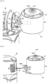
- FIG. 1 represents an embodiment of a household food preparation system 10 comprising on the one hand a household food preparation appliance 12 , of the food processor type, and an accessory assembly 14 , here of the “mini-chopper” type.
- the household food preparation appliance 12 comprises a base, here in the form of a foot, comprising a substantially horizontal base 16 and a leg 18 which extends vertically upwards from the base 16 .
- the base is intended to rest on a horizontal work surface.
- the base 16 can also support a main working container, here in the form of a tank 20 , which is generally removable.
- the household food preparation appliance 12 also includes a head 22 which, in this example, is articulated on the base around a horizontal axis A1 , here at the upper end of the leg 18 .
- the head 22 In cases where the head 22 is articulated around the horizontal axis A1 , it can be movable between a raised position, not shown, in which the tank 20 can be easily removed from the base 16 , and a working position, illustrated in particular on the Fig. 1 .
- the notions of "horizontal”, “vertical”, “top” and “bottom”, and the notions of orientations which result therefrom, refer to normal orientations of the electrical household food preparation appliance 12 in an operating situation when its base is placed on a horizontal work surface.
- the head 22 of the household food preparation appliance 12 has a shape which extends in a longitudinal direction, horizontal in the working position, with a rear longitudinal portion by which it is linked to the base, and a front longitudinal part which is extends overhanging above the base 16 and the tank 20.
- the head 22 contains a main motor 30 , preferably an electric motor, illustrated in the Fig. 2 , the start-up and speed of which can be controlled for example by a control button 24 arranged for example on a side face of the leg 18 .
- the tank 20 is for example removably mounted on the base 16 by a bayonet connection.
- the front longitudinal portion of the head 22 comprises a lower main plate 26 comprising means for driving a main working tool 32 , preferably according to a planetary movement.
- the main plate 26 is rotatable about a central axis, and comprises a rotary drive shaft eccentric with respect to the central axis and ensuring the rotational drive of a main working tool 32 on himself.
- This rotating assembly is connected to the main engine 30 via a kinematic chain which generally implements an epicyclic gear train according to a design very widely known to those skilled in the art.
- the main working tool 32 carried and driven by the main plate 26 , is, in the working position, engaged inside the tank 20 to act on food contained in the tank 20 .
- the main working tool 32 is for example a kneading tool.
- the main motor 30 arranged inside the head 22 comprises a motor shaft oriented along a horizontal motor axis A0 .
- This motor shaft may have a front end connected to the kinematic drive chain of the main plate 26.
- the household food preparation appliance 12 comprises at least one auxiliary output 38 comprising an appliance hooking claw 40 and an auxiliary output shaft 42 which is driven in rotation by the main motor 30 of the head 22 , configured for the attachment and drive of a removable accessory assembly.
- two elements are detachably linked if they can be coupled and uncoupled, or hooked and unhooked, in a simple manner by an end user of an electrical household food preparation system according to the invention, it that is to say by an end user of electrical household food preparation appliances.
- these operations can be done without tools, or else with the aid of one or more tools according to a very simple procedure.
- the operating mode for coupling and uncoupling, and/or for hooking and unhooking two detachably linked elements preferably comprises a single gesture, for example pushing or pulling or turning or screwing, etc., or a combination of two gestures such as pushing -turn, pull-screw, push-screw, etc.
- a removable connection will thus be to be distinguished from a removable connection, a removable connection being provided for example to allow maintenance or repair operations on the internal organs of a household cooking appliance, generally requiring tools and generally requiring several successive operations to allow disassembly, and being reserved for example to a repairer, outside of normal use of the household food preparation appliance.
- the auxiliary output 38 is arranged at the rear end of the head 22 .
- the auxiliary output 38 is a rear auxiliary output.
- the auxiliary output shaft 42 is a rear auxiliary output shaft.
- the device attachment claw 40 of the auxiliary outlet 38 is formed by a series of slots 40' arranged in a casing wall of the end rear of the head 22.
- the auxiliary output shaft 42 may be formed by the rear end of the motor shaft, or by a separate shaft driven by the main motor 30. As shown in the figures 1 to 4 , the auxiliary output shaft 42 is formed by a rear end of the motor shaft.
- the auxiliary output shaft 42 has a coupling means, or coupler, which can for example be a square drive, in the example a female square 61 , the coupling means being accessible from outside the head 22 through an access orifice 44 provided in the casing wall of the head 22.
- a coupling means or coupler, which can for example be a square drive, in the example a female square 61 , the coupling means being accessible from outside the head 22 through an access orifice 44 provided in the casing wall of the head 22.
- the auxiliary output shaft 42 of the auxiliary output 38 of the electrical culinary 12 is parallel to the motor axis A0.
- the drive kinematic chain of the main plate 26 can also drive in rotation an auxiliary output shaft before another auxiliary output 34 before, arranged on the front end of the head 22 .
- the auxiliary output shaft 42 is driven in rotation by the main motor 30 of the head 22 at an auxiliary output speed equal to the motor speed of the motor shaft.
- the electrical household food preparation system 10 also comprises at least one removable accessory assembly 14 , in particular of the mini-chopper type as shown, also of the blender type, intended to be hooked to the household food preparation appliance 12 and to be motorized to the means of the auxiliary output 38 .
- an accessory assembly 14 firstly comprises a resealable enclosure 45 delimiting a closed internal space intended to accommodate food to be prepared.
- this reclosable enclosure 45 is delimited on the one hand by a receptacle, formed by a tool holder base 46 and by a skirt 47 , and on the other hand by a bell 48 which is connected to the tool holder base 46 to close the reclosable enclosure 45 .
- the skirt 47 extends towards the top around a tool axis A2 from the tool holder base 46.
- the tool holder base 46 is for example of substantially circular geometry around the tool axis A2.
- the skirt 47 may have a cylindrical geometry.
- the bell 48 has a substantially transverse upper wall and a side wall which surrounds the skirt 47. If desired, the side wall of the bell 48 can be cylindrical of revolution around the tool axis A2 which extends downwards from the periphery of the upper wall. The cylindrical side wall of the bell 48 then surrounds coaxially from the outside the skirt 47, which is cylindrical.
- the lower edge of the bell 48 is provided with a means of connection with the tool holder base 46 , with for example complementary threads on the tool holder base 46 and on the lower edge of the bell 48 , or even , as a variant, with a bayonet connection, making it possible to removably assemble the bell 48 to the tool holder base 46 to delimit a closed internal space, preferably sealed.
- the removable accessory assembly comprises a cutting tool 50 , rotatable around the tool axis A2 , which can be qualified as the working axis for the cutting tool 50 .
- the cutting tool 50 is contained in the closed internal space when, in the example, the bell 48 is assembled on the tool holder base 46 .
- the cutting tool 50 is arranged in the accessory assembly 14 so that the tool axis A2 is arranged axially at the center of the closed internal space delimited by the reclosable enclosure 45 of the accessory assembly 14 in the closed configuration.
- the cutting tool 50 has a central hub 52 and at least one cutting blade 54 extending radially with respect to the tool axis A2 from the central hub 52 .
- the cutting tool 50 preferably has at least two cutting blades 54 extending in opposite radial directions on either side of the tool axis A2.
- the cutting tool 50 comprises six cutting blades 54 which extend radially from the central hub 52 , distributed evenly around the tool axis A2 .
- the cutting blades 54 In top view along the tool axis A2 , the cutting blades 54 according to the example are oriented in a substantially rectilinear manner in the radial direction, but it is known that they can present, according to such a top view, a angulation or curvature with respect to a ray from of tool axis A2 .
- the cutting blades 54 have an angulation or a curvature, upwards or downwards, with respect to a direction perpendicular to the tool axis A2 .
- the cutting tool 50 is, in the example, secured to the tool holder base 46 .
- the cutting tool 50 can be secured to the tool holder base 46 in a removable manner, for example by snapping onto a coupler rotatably mounted on the tool holder base 46 .
- the accessory assembly 14 comprises in all cases on the one hand an accessory assembly attachment claw 56 to allow removable attachment of the accessory assembly 14 on the household appliance preparation 12 , and on the other hand a rotary input shaft 58 having a coupler 60 for mechanically coupling with the auxiliary output shaft 42 of the auxiliary output 38.
- the auxiliary output shaft 42 is coupled mechanically with the rotating input shaft 58.
- the coupler 60 should permit easy coupling and uncoupling, preferably without tools.
- accessory assembly hook 56 includes a series of hook tabs which extend from an accessory assembly housing 14 and which are intended to engage slots 40' of the rear end of the head 22 to ensure the attachment of the accessory assembly 14 on the household food preparation appliance 12.
- the accessory assembly attachment claw 56 cooperates with the appliance attachment claw 40.
- the slats providing the slots 40' may comprise snap-fastening or elastic interlocking means.
- the accessory assembly attachment claw 56 could take another form, for example the form of a bayonet attachment, the form of one or more attachment hooks, the form of a thread , etc....
- the coupler 60 of the rotary input shaft 58 which provides the rotational coupling with the auxiliary output shaft 42 , can for example have a complementary shape from that of a coupler of the intermediate output shaft, with for example a male square and a female square complementary to one of the other, or any other mechanical coupling for transmitting a torque in rotation.
- the coupler 60 allows this coupling by simple engagement of complementary shapes, without requiring intervention with a tool.
- accessory assembly hook 56 and coupler 60 are clearly separated from each other.
- the electrical household food preparation system 10 comprises a mechanical bevel transmission 62 arranged between the main motor 30 of the electrical household food preparation appliance 12 and the cutting tool 50 of the accessory assembly 14.
- this mechanical transmission with bevel gear 62 is not integrated inside the household food preparation appliance 12 , and in particular is not integrated between the main motor 30 and the auxiliary output shaft 42 of the auxiliary output 38.
- this mechanical transmission with bevel gear 62 is part of the accessory assembly 14 . More specifically, the bevel gear mechanical transmission 62 is included in the accessory assembly 14 by being arranged between an input shaft of the accessory assembly 14 and the cutting tool 50 .
- the invention can be implemented according to two main families of embodiments.
- the accessory assembly 14 is an integrated assembly in which a lower wall of the resealable enclosure 45 , here for example the tool-holder base 46 , is linked in a non-removable manner to a box 64 which encloses the mechanical transmission with transmission corner 62.
- the accessory assembly 14 comprises an accessory holder 70 and an accessory 72 detachably linked, in which the bevel gear mechanical transmission 62 is integrated into the accessory holder 70 and in which the reclosable enclosure 45 forms part, with the cutting tool 50 , of the accessory 72.
- the mechanical transmission with bevel gear 62 can advantageously be received inside a box 64.
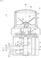
- the bevel gear mechanical transmission 62 comprises a first toothed wheel 66 , for example with conical teeth, which is rotatably mounted in the housing 64 about a horizontal axis, which is for example aligned with the motor axis A0 of the main motor 30 , and which meshes with a second toothed wheel 68 , for example with conical teeth, which is rotatably mounted in the housing 64 about a vertical axis, for example aligned with the axis of tool A2 of the cutting tool 50 , perpendicular to the horizontal axis of the first toothed wheel 66.
- the accessory holder 70 comprises a first attachment claw complementary to the device attachment claw 40 of the auxiliary output 38 of the household food preparation appliance 12 to allow the attachment of the accessory holder 70 to the household food preparation appliance 12.
- the first hooking claw corresponds to the hooking claw of accessory assembly 56 including hooking tabs extending from housing 64 of accessory carrier 70.
- Accessory carrier 70 further includes rotatable input shaft 58 , which is configured to mechanically mate with the auxiliary output shaft 42 of the auxiliary output 38 , and which is mechanically connected directly or indirectly to the first toothed wheel 66 of the bevel gear mechanical transmission 62.
- the rotary input shaft 58 is mechanically connected directly to the first toothed wheel 66 of the bevel mechanical transmission 62.
- the accessory holder 70 comprises a second attachment claw 74 configured to allow attachment of the accessory 72.
- This second attachment claw 74 may have the form of a bayonet attachment, as illustrated in Figs. 3 and 4 , or any other form allowing the attachment, preferably without tools, or else with a very simple tool, of the accessory 72 on the accessory holder 70.
- the accessory 72 for example its base holder tool 46 , has, preferably on an underside facing the accessory holder 70 , a third attachment claw complementary to the second attachment claw 74.
- the accessory holder 70 comprises a rotary output shaft 76 comprising a coupler 78 configured to allow the tool to be driven in rotation. cutting edge 50 of the accessory 72 hooked on the second hooking claw 74.
- the coupler 78 is driven in rotation around the tool axis A2 by the second toothed wheel 68 of the mechanical transmission with bevel gear 62.
- This coupler 78 must allow easy coupling and uncoupling, preferably without tools.
- the angle transmission mechanical transmission 62 is therefore arranged between the rotary input shaft and the rotary output shaft 76 of the accessory holder 70.
- the rotary input shaft 58 of the accessory holder 70 and the accessory assembly hooking claw 56 of the accessory holder 70 are arranged on the same first face of the accessory holder 70 which is configured to be turned. opposite and facing the rear end of the head 22 of the household food preparation appliance 12.
- the accessory assembly hooking claw 56 of the accessory holder 70 is arranged on a first face of the accessory holder 70
- the second attachment claw 74 of the accessory holder 70 is arranged on a second face of the accessory holder 70 , the second face being separate from the first face and having a different orientation from that of the first side.
- the first face and the second face of the accessory holder 70 are faces perpendicular to each other. These are external faces of the box 64 in which the angle transmission mechanical transmission 62, these faces defining between them a convex geometry.
- the rotary output shaft 76 of the accessory holder 70 is arranged in the center of the second attachment claw 74 of the accessory holder 70.
- the mechanical transmission with angle transmission 62 can be configured so as not to modify the angular speed of rotation between the rotary input shaft 58 of the accessory assembly 14 and the cutting tool 50.
- the mechanical transmission arranged between the shaft rotary input shaft 58 and cutting tool 50 of accessory assembly 14 is configured to multiply an input angular velocity of rotary input shaft 58 into a working angular velocity of cutting tool 50 by a speed multiplication ratio strictly greater than 1, to obtain a higher value of the angular speed of rotation of the cutting tool 50 for a given value of the angular speed of rotation of the main motor 30.
- This speed multiplication ratio can by example be between 1.1 and 1.4.
- the bevel mechanical transmission 62 may be configured to multiply an input angular speed of the rotary input shaft 58 into a angular working speed of the cutting tool 50 by a speed multiplication ratio strictly less than 1, for example between 0.1 and 0.9.
- the multiplication ratio can be obtained by a difference in the dimensions and the number of teeth of these two toothed wheels.
- the bevel gear mechanical transmission 62 may also comprise, in addition to the bevel gear means, a speed multiplier, for example in the form of two gear wheels of different diameter .
- the embodiments of the invention in which the accessory assembly 14 is an integrated assembly, including in a non-separable manner the accessory part and the part forming the angle transmission mechanical transmission 62 , have the advantage of being able to be hooked onto an auxiliary output comprising a horizontal auxiliary output shaft, in particular on the auxiliary output 38 , but also on another output auxiliary such as for example the other front auxiliary output 34 , or even another side auxiliary output, while maintaining a vertical tool axis A2 for the cutting tool 50 , which is necessary for the proper functioning of an accessory of the type “blender” or “mini-chopper” type.
- the accessory assembly 14 comprises two separate parts, one comprising the accessory 72 and the other comprising an accessory holder 70 provided with the mechanical transmission with angle transmission 62 , the two parts being detachably linked.
- the electrical household food preparation system 10 only drives the angle transmission mechanical transmission 62 when the latter is necessary, that is to say only when the accessory assembly 14 is used.
- the accessory assembly 14 can be unhooked of the electrical household food preparation appliance 12 , preventing any drive of the bevel gear mechanical transmission 62 , which reduces the overall noise generated by the electrical household food preparation appliance 12 , and which reduces the wear of the mechanical transmission with angle transmission 62.
- the same accessory holder 70 can be provided to be used with two or more separate accessories 72 , whether they are of the same type, for for example at least two accessories of the mini-chopper type, or whether they are of different types, for example at least one accessory of the mini-chopper type and at least one accessory of the "blender" type.
- a household food preparation system 10 may comprise a first accessory and a second accessory, both configured to be hooked alternately on the second hooking claw 74 of the accessory holder 70.
- Each of the two accessories comprises a working cutting tool 50 intended to be driven by the output shaft of the accessory holder 70 when the corresponding accessory is hooked onto the second hooking claw 74 of the accessory holder 70.
- the household food preparation system 10 has the great advantage of providing, for a single household food preparation appliance 12 , several distinct accessories, of different types or not, and a single accessory holder 70 comprising a mechanical transmission with bevel gear 62 compatible with the household food preparation appliance 12 and with these separate accessories.
- This of course makes it possible to limit the cost and the overall size of the electrical household food preparation system 10.
- the accessory holder 70 being removable, the advantages mentioned above, linked in particular to the reduction of the noise of the household food preparation appliance 12 when the drive of the accessory holder 70 with mechanical transmission with bevel gear 62 is not necessary.
- the accessory assembly 14 as such comprises a bevel gear mechanical transmission.
- angle 62 arranged between the rotary input shaft 58 of the accessory assembly 14 and a cutting tool 50 of the accessory assembly 14 .
- the second toothed wheel 68 with conical teeth has a shaft which extends upwards along the tool axis A2 , through the tool holder base 46 , and which carries at its end the cutting tool 50 , directly as shown in Fig. 6 , or indirectly via a coupler.
Landscapes
- Engineering & Computer Science (AREA)
- Food Science & Technology (AREA)
- Mechanical Engineering (AREA)
- Food-Manufacturing Devices (AREA)
Claims (13)
- Elektrisches Haushaltsküchen-Zubereitungssystem (10), in der Art Folgendes umfassend:- eine elektrische Haushaltsküchen-Zubereitungseinrichtung (12), umfassend:- einen Sockel, der eine Basis (16) aufweist, die konfiguriert ist, um einen Behälter (20) aufzunehmen,- einen mit dem Sockel verbundenen Kopf (22), wobei der Kopf (22) Folgendes aufweist- einen Hauptmotor (30), der im Inneren des Kopfes (22) angeordnet ist, und eine Motorwelle aufweist, die entlang einer horizontalen Motorachse (AO) ausgerichtet ist,- eine Hauptplatine (26), die unter dem Kopf (22) angeordnet ist, durch den Hauptmotor (30) in Drehung angetrieben wird, und konfiguriert ist, um ein Hauptarbeitswerkzeug (32) oberhalb der Basis (16) entsprechend einer Hauptarbeitsbewegung anzutreiben,- einen Hilfsausgang (38), umfassend eine Einrastklaue für eine Einrichtung (40) und eine Hilfsausgangswelle (42), die durch den Hauptmotor (30) des Kopfes (22) in Drehung angetrieben wird,wobei das elektrische Haushaltsküchen-Zubereitungssystem (10) darüber hinaus eine abnehmbare Zubehör-Untereinheit (14) umfasst, die Folgendes aufweist:- eine verschließbare Einschließung (45), die einen geschlossenen Innenraum begrenzt, der dazu bestimmt ist, zuzubereitende Nahrungsmittel aufzunehmen,- ein Schneidwerkzeug (50), das um eine vertikale Werkzeugachse (A2) herum drehbar ist, wobei das Schneidwerkzeug (50) in dem geschlossenen Innenraum enthalten ist, und eine zentrale Nabe (52) mit mindestens einer Schneidklinge (54) aufweist, die sich in Bezug auf die Werkzeugachse (A2) radial aus der zentralen Nabe (52) heraus erstreckt,- eine Einrastklaue für eine Zubehör-Untereinheit (56) um das lösbare Einrasten der Zubehör-Untereinheit (14) an der elektrischen Haushaltsküchen-Zubereitungseinrichtung (12) zu erlauben,- eine Eingangsdrehwelle (58), die einen Koppler (60) aufweist, um sich mechanisch an die Hilfsausgangswelle (42) zu koppeln, und das elektrische Haushaltsküchen-Zubereitungssystem (10) ein mechanisches Winkelgetriebe (62) umfasst, das zwischen dem Hauptmotor (30) und dem Schneidwerkzeug (50) der Zubehör-Untereinheit (14) angeordnet ist, wobei die Hilfsausgangswelle (42) der elektrischen Haushaltsküchen-Zubereitungseinrichtung (12) parallel zur Motorachse (AO) liegt, das mechanische Winkelgetriebe (62) in der Zubehör-Untereinheit (14) enthalten ist, und dabei zwischen der Eingangsdrehwelle (58) der Zubehör-Untereinheit (14) und dem Schneidwerkzeug (50) angeordnet ist, eine elektrische Haushaltsküchen-Zubereitungseinrichtung, in der die Hilfsausgangswelle mechanisch an die Eingangsdrehwelle gekoppelt ist, und in der die Eingangsdrehwelle mechanisch direkt mit einem ersten Zahnrad des mechanischen Winkelgetriebes verbunden istdadurch gekennzeichnet, dass die Hilfsausgangswelle (42) eine hintere Hilfsausgangswelle ist, dadurch, dass die Hilfsausgangswelle (42) durch ein hinteres Ende der Motorwelle gebildet wird.
- Elektrisches Haushaltsküchen-Zubereitungssystem (10) nach Anspruch 1, dadurch gekennzeichnet, dass das mechanische Winkelgetriebe (62) konfiguriert ist, um eine Eingangswinkelgeschwindigkeit der Eingangsdrehwelle (58) durch ein Geschwindigkeitsübersetzungsverhältnis, das streng größer als 1 ist, vorzugsweise zwischen 1,1 und 1,4 liegt, in eine Arbeitswinkelgeschwindigkeit des Schneidwerkzeugs (50) zu übersetzen.
- Elektrisches Haushaltsküchen-Zubereitungssystem (10) nach Anspruch 1, dadurch gekennzeichnet, dass das mechanische Winkelgetriebe (62) konfiguriert ist, um eine Eingangswinkelgeschwindigkeit der Eingangsdrehwelle (58) durch ein Geschwindigkeitsuntersetzungsverhältnis, das streng kleiner als 1 ist, vorzugsweise zwischen 0,1 und 0,9 liegt, in eine Arbeitswinkelgeschwindigkeit des Schneidwerkzeugs (50) zu untersetzen.
- Elektrisches Haushaltsküchen-Zubereitungssystem (10) nach einem der Ansprüche 1 bis 3, dadurch gekennzeichnet, dass die Hilfsausgangswelle (42) durch den Hauptmotor (30) des Kopfes (22) mit einer Hilfsausgangsgeschwindigkeit in Drehung angetrieben wird, die gleich der Motorwinkelgeschwindigkeit der Motorwelle ist.
- Elektrisches Haushaltsküchen-Zubereitungssystem nach einem der Ansprüche 1 bis 4, dadurch gekennzeichnet, dass der Kopf (22) ein Gehäuse aufweist, das eine Verlängerung in der Richtung der Motorwelle zwischen einem hinteren Ende, durch das der Kopf (22) mit dem Sockel verbunden ist, und einem vorderen Ende freitragend oberhalb der Basis (16) aufweist, und dadurch, dass der Hilfsausgang (38) ein hinterer Hilfsausgang ist, der auf einer Rückseite des hinteren Endes des Kopfes (22) angeordnet ist.
- Elektrisches Haushaltsküchen-Zubereitungssystem (10) nach einem der Ansprüche 1 bis 5, dadurch gekennzeichnet, dass die Eingangsdrehwelle (58) der abnehmbaren Zubehör-Untereinheit (14) und die Werkzeugachse (A2) des Schneidwerkzeugs (50) senkrecht sind, und dadurch, dass das mechanische Winkelgetriebe (62) ein 90°-Winkelgetriebe umfasst.
- Elektrisches Haushaltsküchen-Zubereitungssystem (10) nach einem der Ansprüche 1 bis 6, dadurch gekennzeichnet, dass die Zubehör-Untereinheit (14) eine integrierte Untereinheit ist, in der eine Werkzeugträgerbasis (46) der verschließbaren Einschließung (45) in nicht abnehmbarer Art und Weise an einen Kasten (64) angeschlossen ist, der das mechanische Winkelgetriebe (62) enthält.
- Elektrisches Haushaltsküchen-Zubereitungssystem (10) nach einem der Ansprüche 1 bis 6, dadurch gekennzeichnet, dass die Zubehör-Untereinheit (14) einen Zubehör-Träger (70) und ein Zubehör (72) umfasst, die auf abnehmbare Art und Weise verbunden sind, wobei das mechanische Winkelgetriebe (62) im Zubehör-Träger (70) integriert ist, und wobei die verschließbare Einschließung (45) dem Zubehör (72) angehört.
- Elektrisches Haushaltsküchen-Zubereitungssystem (10) nach Anspruch 8, dadurch gekennzeichnet, dass der Zubehör-Träger (70) umfasst:- die Einrastklaue für die Zubehör-Untereinheit (56) ergänzend zur Einrastklaue der Einrichtung (40) für den Hilfsausgang (38) der elektrischen Haushaltsküchen-Zubereitungseinrichtung (12) um das Einrasten des Zubehör-Trägers (70) an der elektrischen Haushaltsküchen-Zubereitungseinrichtung (12) zu erlauben,- eine Eingangsdrehwelle (58), konfiguriert, um mechanisch an die Hilfsausgangswelle (42) gekoppelt zu werden,- eine zweite Einrastklaue (74), konfiguriert, um das Einrasten des Zubehörs (72) zu erlauben,- eine Ausgangsdrehwelle (76), konfiguriert, um den Drehantrieb des Schneidwerkzeugs (50) des Zubehörs (72) zu erlauben, das in der zweiten Einrastklaue (74) eingerastet ist,und dadurch, dass das mechanische Winkelgetriebe (62) zwischen der Eingangsdrehwelle (58) und der Ausgangsdrehwelle (76) des Zubehör-Trägers (70) angeordnet ist.
- Elektrisches Haushaltsküchen-Zubereitungssystem (10) nach Anspruch 9, dadurch gekennzeichnet, dass die Eingangsdrehwelle (58) des Zubehör-Trägers (70) und die Einrastklaue der Zubehör-Untereinheit (56) des Zubehör-Trägers (70) auf einer selben ersten Seite des Zubehör-Trägers (70) angeordnet sind.
- Elektrisches Haushaltsküchen-Zubereitungssystem (10) nach einem der Ansprüche 9 oder 10, dadurch gekennzeichnet, dass die Ausgangsdrehwelle (76) des Zubehör-Trägers (70) in der Mitte der zweiten Einrastklaue (74) des Zubehör-Trägers (70) angeordnet ist.
- Elektrisches Haushaltsküchen-Zubereitungssystem (10) nach einem der Ansprüche 9 bis 11, dadurch gekennzeichnet, dass die Einrastklaue der Zubehör-Untereinheit (56) des Zubehör-Trägers (70) auf einer ersten Seite des Zubehör-Trägers (70) angeordnet ist, und dadurch, dass die zweite Einrastklaue (74) des Zubehör-Trägers (70) auf der zweiten Seite des Zubehör-Trägers (70) angeordnet ist, wobei sich die zweite Seite von der ersten Seite unterscheidet, und eine unterschiedliche Ausrichtung zu jener der ersten Seite aufweist.
- Elektrisches Haushaltsküchen-Zubereitungssystem (10) nach einem der Ansprüche 9 bis 12, dadurch gekennzeichnet, dass es ein erstes Zubehör und ein zweites Zubehör umfasst, alle beide konfiguriert, um abwechselnd in der Einrastklaue (74) des Zubehör-Trägers (70) einzurasten.
Applications Claiming Priority (1)
| Application Number | Priority Date | Filing Date | Title |
|---|---|---|---|
| FR1874262A FR3091160B1 (fr) | 2018-12-27 | 2018-12-27 | Système électroménager de préparation culinaire comportant un ensemble accessoire à renvoi d’angle, ensemble accessoire, et porte-accessoire pour un tel système électroménager de préparation culinaire |
Publications (3)
| Publication Number | Publication Date |
|---|---|
| EP3673777A1 EP3673777A1 (de) | 2020-07-01 |
| EP3673777B1 true EP3673777B1 (de) | 2023-08-23 |
| EP3673777C0 EP3673777C0 (de) | 2023-08-23 |
Family
ID=66776505
Family Applications (1)
| Application Number | Title | Priority Date | Filing Date |
|---|---|---|---|
| EP19213620.8A Active EP3673777B1 (de) | 2018-12-27 | 2019-12-04 | Elektrisches haushaltsküchen-vorbereitungssystem mit einer eckenübertragungs-zubehöruntereinheit, einer zubehöruntereinheit und einer zubehörhalter für ein solches haushaltsküchen-vorbereitungssystem |
Country Status (3)
| Country | Link |
|---|---|
| EP (1) | EP3673777B1 (de) |
| CN (2) | CN212996114U (de) |
| FR (1) | FR3091160B1 (de) |
Cited By (1)
| Publication number | Priority date | Publication date | Assignee | Title |
|---|---|---|---|---|
| EP4573994A1 (de) * | 2023-12-22 | 2025-06-25 | BSH Hausgeräte GmbH | Haushaltsgerät, insbesondere haushaltsmixer |
Families Citing this family (2)
| Publication number | Priority date | Publication date | Assignee | Title |
|---|---|---|---|---|
| FR3091160B1 (fr) * | 2018-12-27 | 2021-01-08 | Seb Sa | Système électroménager de préparation culinaire comportant un ensemble accessoire à renvoi d’angle, ensemble accessoire, et porte-accessoire pour un tel système électroménager de préparation culinaire |
| FR3124064B1 (fr) * | 2021-06-18 | 2023-11-24 | Seb Sa | Appareil électroménager de préparation culinaire avec châssis structurel interne et capotage |
Family Cites Families (10)
| Publication number | Priority date | Publication date | Assignee | Title |
|---|---|---|---|---|
| DE2551842C3 (de) | 1975-11-19 | 1979-03-01 | Bosch-Siemens Hausgeraete Gmbh, 7000 Stuttgart | Elektromotorisch betriebenes Antriebsaggregat, insbesondere für Küchenmaschinen o.dgl |
| CN2383454Y (zh) * | 1999-05-21 | 2000-06-21 | 陆翔云 | 可变速多功能食品加工机 |
| FR2940033B1 (fr) * | 2008-12-22 | 2013-03-29 | Seb Sa | Appareil electromenager de preparation culinaire comportant un premier et un deuxieme recipients de travail sur un boitier |
| FR2968918B1 (fr) * | 2010-12-17 | 2013-02-08 | Seb Sa | Appareil electromenager de preparation culinaire comportant un socle supportant une cuve et un bras solidaire du socle |
| FR2971688B1 (fr) * | 2011-02-18 | 2013-02-15 | Seb Sa | Appareil electromenager de preparation culinaire comportant des moyens pour l'entrainement d'un outil de travail selon un mouvement planetaire |
| FR2983393B1 (fr) * | 2011-12-02 | 2014-08-29 | Seb Sa | Accessoire de support de boitier motorise d’appareil electromenager de preparation culinaire |
| CN202775969U (zh) | 2012-06-12 | 2013-03-13 | 主力电器制品厂有限公司 | 一种家用立式食品搅拌机 |
| US9675101B2 (en) * | 2013-03-15 | 2017-06-13 | Whirlpool Corporation | High performance adjustable juicer with whole foods feed chute |
| US9167938B2 (en) * | 2013-03-15 | 2015-10-27 | Whirlpool Corporation | Food processor mixer attachment |
| FR3091160B1 (fr) * | 2018-12-27 | 2021-01-08 | Seb Sa | Système électroménager de préparation culinaire comportant un ensemble accessoire à renvoi d’angle, ensemble accessoire, et porte-accessoire pour un tel système électroménager de préparation culinaire |
-
2018
- 2018-12-27 FR FR1874262A patent/FR3091160B1/fr active Active
-
2019
- 2019-12-04 EP EP19213620.8A patent/EP3673777B1/de active Active
- 2019-12-26 CN CN201922381865.8U patent/CN212996114U/zh not_active Withdrawn - After Issue
- 2019-12-26 CN CN201911364744.0A patent/CN111374574B/zh active Active
Cited By (1)
| Publication number | Priority date | Publication date | Assignee | Title |
|---|---|---|---|---|
| EP4573994A1 (de) * | 2023-12-22 | 2025-06-25 | BSH Hausgeräte GmbH | Haushaltsgerät, insbesondere haushaltsmixer |
Also Published As
| Publication number | Publication date |
|---|---|
| EP3673777A1 (de) | 2020-07-01 |
| CN111374574A (zh) | 2020-07-07 |
| CN111374574B (zh) | 2024-11-26 |
| FR3091160A1 (fr) | 2020-07-03 |
| CN212996114U (zh) | 2021-04-20 |
| EP3673777C0 (de) | 2023-08-23 |
| FR3091160B1 (fr) | 2021-01-08 |
Similar Documents
| Publication | Publication Date | Title |
|---|---|---|
| EP2085005B1 (de) | Elektrisches Haushaltsgerät zur Essenszubereitung, das ein Gehäuse mit einem Motor und einem Behälter umfasst, in den ein Rührwerkzeug eingeführt werden kann | |
| EP2515721B1 (de) | Elektrisches küchengerät mit druckschraube und vorschneidelement | |
| EP2675331B1 (de) | Elektrisches haushaltsgerät zur speisenzubereitung mit einer vorrichtung für den antrieb eines arbeitswerkzeuges in einer planetenbewegung | |
| EP3673777A1 (de) | Elektrisches haushaltsküchen-vorbereitungssystem mit einer eckenübertragungs-zubehöruntereinheit, einer zubehöruntereinheit und einer zubehörhalter für ein solches haushaltsküchen-vorbereitungssystem | |
| EP2206455A1 (de) | Haushaltsgerät zur Essenszubereitung, das einen ersten und einen zweiten Arbeitsbehälter auf einem Gehäuse umfasst | |
| EP1139838B1 (de) | Mehrzweckküchenmaschine | |
| EP2859823B1 (de) | Zubehör zum Schneiden von Lebensmitteln, das gesicherte Drehantriebsmittel eines Schneidwerkzeugs umfasst | |
| EP2892405A1 (de) | Haushaltsvorrichtung zur lebensmittelherstellung mit einem haken zur teigmischung durch planetengetriebebewegungen | |
| EP3912537B1 (de) | Elektrohaushaltsgerät und -system zur zubereitung von speisen mit koplanarem antrieb | |
| FR3010884A1 (fr) | Accessoire pour decouper des aliments dont un outil de coupe secondaire fixe comprend des moyens de prehension | |
| EP4346528B1 (de) | Elektrisches haushaltsgerät zur zubereitung von lebensmitteln | |
| EP3079545A1 (de) | Haushaltsvorrichtung zur speisenzubereitung mit einem unterarm und einem drehbar am unterarm montierten oberarm | |
| EP4153014B1 (de) | Elektrisches haushaltsgerät und system zur lebensmittelzubereitung mit zwischenübertragungsrad zwischen zwei werkzeugkopplern | |
| WO2015033054A1 (fr) | Dispositif de préparation d'aliments pour extraire des jus et/ou des coulis et contrôler leur écoulement | |
| WO2023062320A1 (fr) | Appareil de cuisson à induction équipé d'un organe d'accouplement rotatif | |
| EP2949247B1 (de) | Vorrichtung zur lebensmittelzubereitung, die an die extraktion von saft und/oder püree angepasst ist | |
| FR3044887A1 (fr) | Dispositif de preparation culinaire | |
| WO2024056608A1 (fr) | Dispositif de préparation culinaire pour un appareil de préparation culinaire | |
| FR2820021A1 (fr) | Accessoires de travail rotatifs pour appareil electromenager de preparation culinaire |
Legal Events
| Date | Code | Title | Description |
|---|---|---|---|
| PUAI | Public reference made under article 153(3) epc to a published international application that has entered the european phase |
Free format text: ORIGINAL CODE: 0009012 |
|
| STAA | Information on the status of an ep patent application or granted ep patent |
Free format text: STATUS: THE APPLICATION HAS BEEN PUBLISHED |
|
| AK | Designated contracting states |
Kind code of ref document: A1 Designated state(s): AL AT BE BG CH CY CZ DE DK EE ES FI FR GB GR HR HU IE IS IT LI LT LU LV MC MK MT NL NO PL PT RO RS SE SI SK SM TR |
|
| AX | Request for extension of the european patent |
Extension state: BA ME |
|
| STAA | Information on the status of an ep patent application or granted ep patent |
Free format text: STATUS: REQUEST FOR EXAMINATION WAS MADE |
|
| 17P | Request for examination filed |
Effective date: 20201222 |
|
| RBV | Designated contracting states (corrected) |
Designated state(s): AL AT BE BG CH CY CZ DE DK EE ES FI FR GB GR HR HU IE IS IT LI LT LU LV MC MK MT NL NO PL PT RO RS SE SI SK SM TR |
|
| STAA | Information on the status of an ep patent application or granted ep patent |
Free format text: STATUS: EXAMINATION IS IN PROGRESS |
|
| 17Q | First examination report despatched |
Effective date: 20220726 |
|
| GRAP | Despatch of communication of intention to grant a patent |
Free format text: ORIGINAL CODE: EPIDOSNIGR1 |
|
| STAA | Information on the status of an ep patent application or granted ep patent |
Free format text: STATUS: GRANT OF PATENT IS INTENDED |
|
| INTG | Intention to grant announced |
Effective date: 20230314 |
|
| GRAS | Grant fee paid |
Free format text: ORIGINAL CODE: EPIDOSNIGR3 |
|
| GRAA | (expected) grant |
Free format text: ORIGINAL CODE: 0009210 |
|
| STAA | Information on the status of an ep patent application or granted ep patent |
Free format text: STATUS: THE PATENT HAS BEEN GRANTED |
|
| AK | Designated contracting states |
Kind code of ref document: B1 Designated state(s): AL AT BE BG CH CY CZ DE DK EE ES FI FR GB GR HR HU IE IS IT LI LT LU LV MC MK MT NL NO PL PT RO RS SE SI SK SM TR |
|
| REG | Reference to a national code |
Ref country code: GB Ref legal event code: FG4D Free format text: NOT ENGLISH |
|
| REG | Reference to a national code |
Ref country code: CH Ref legal event code: EP |
|
| REG | Reference to a national code |
Ref country code: DE Ref legal event code: R096 Ref document number: 602019035504 Country of ref document: DE |
|
| REG | Reference to a national code |
Ref country code: IE Ref legal event code: FG4D Free format text: LANGUAGE OF EP DOCUMENT: FRENCH |
|
| U01 | Request for unitary effect filed |
Effective date: 20230922 |
|
| U07 | Unitary effect registered |
Designated state(s): AT BE BG DE DK EE FI FR IT LT LU LV MT NL PT SE SI Effective date: 20230928 |
|
| U20 | Renewal fee for the european patent with unitary effect paid |
Year of fee payment: 5 Effective date: 20231123 |
|
| PG25 | Lapsed in a contracting state [announced via postgrant information from national office to epo] |
Ref country code: GR Free format text: LAPSE BECAUSE OF FAILURE TO SUBMIT A TRANSLATION OF THE DESCRIPTION OR TO PAY THE FEE WITHIN THE PRESCRIBED TIME-LIMIT Effective date: 20231124 |
|
| PG25 | Lapsed in a contracting state [announced via postgrant information from national office to epo] |
Ref country code: IS Free format text: LAPSE BECAUSE OF FAILURE TO SUBMIT A TRANSLATION OF THE DESCRIPTION OR TO PAY THE FEE WITHIN THE PRESCRIBED TIME-LIMIT Effective date: 20231223 |
|
| PG25 | Lapsed in a contracting state [announced via postgrant information from national office to epo] |
Ref country code: RS Free format text: LAPSE BECAUSE OF FAILURE TO SUBMIT A TRANSLATION OF THE DESCRIPTION OR TO PAY THE FEE WITHIN THE PRESCRIBED TIME-LIMIT Effective date: 20230823 Ref country code: NO Free format text: LAPSE BECAUSE OF FAILURE TO SUBMIT A TRANSLATION OF THE DESCRIPTION OR TO PAY THE FEE WITHIN THE PRESCRIBED TIME-LIMIT Effective date: 20231123 Ref country code: IS Free format text: LAPSE BECAUSE OF FAILURE TO SUBMIT A TRANSLATION OF THE DESCRIPTION OR TO PAY THE FEE WITHIN THE PRESCRIBED TIME-LIMIT Effective date: 20231223 Ref country code: HR Free format text: LAPSE BECAUSE OF FAILURE TO SUBMIT A TRANSLATION OF THE DESCRIPTION OR TO PAY THE FEE WITHIN THE PRESCRIBED TIME-LIMIT Effective date: 20230823 Ref country code: GR Free format text: LAPSE BECAUSE OF FAILURE TO SUBMIT A TRANSLATION OF THE DESCRIPTION OR TO PAY THE FEE WITHIN THE PRESCRIBED TIME-LIMIT Effective date: 20231124 |
|
| PG25 | Lapsed in a contracting state [announced via postgrant information from national office to epo] |
Ref country code: PL Free format text: LAPSE BECAUSE OF FAILURE TO SUBMIT A TRANSLATION OF THE DESCRIPTION OR TO PAY THE FEE WITHIN THE PRESCRIBED TIME-LIMIT Effective date: 20230823 |
|
| PG25 | Lapsed in a contracting state [announced via postgrant information from national office to epo] |
Ref country code: ES Free format text: LAPSE BECAUSE OF FAILURE TO SUBMIT A TRANSLATION OF THE DESCRIPTION OR TO PAY THE FEE WITHIN THE PRESCRIBED TIME-LIMIT Effective date: 20230823 |
|
| PG25 | Lapsed in a contracting state [announced via postgrant information from national office to epo] |
Ref country code: SM Free format text: LAPSE BECAUSE OF FAILURE TO SUBMIT A TRANSLATION OF THE DESCRIPTION OR TO PAY THE FEE WITHIN THE PRESCRIBED TIME-LIMIT Effective date: 20230823 Ref country code: RO Free format text: LAPSE BECAUSE OF FAILURE TO SUBMIT A TRANSLATION OF THE DESCRIPTION OR TO PAY THE FEE WITHIN THE PRESCRIBED TIME-LIMIT Effective date: 20230823 Ref country code: ES Free format text: LAPSE BECAUSE OF FAILURE TO SUBMIT A TRANSLATION OF THE DESCRIPTION OR TO PAY THE FEE WITHIN THE PRESCRIBED TIME-LIMIT Effective date: 20230823 Ref country code: CZ Free format text: LAPSE BECAUSE OF FAILURE TO SUBMIT A TRANSLATION OF THE DESCRIPTION OR TO PAY THE FEE WITHIN THE PRESCRIBED TIME-LIMIT Effective date: 20230823 Ref country code: SK Free format text: LAPSE BECAUSE OF FAILURE TO SUBMIT A TRANSLATION OF THE DESCRIPTION OR TO PAY THE FEE WITHIN THE PRESCRIBED TIME-LIMIT Effective date: 20230823 |
|
| REG | Reference to a national code |
Ref country code: DE Ref legal event code: R097 Ref document number: 602019035504 Country of ref document: DE |
|
| PLBE | No opposition filed within time limit |
Free format text: ORIGINAL CODE: 0009261 |
|
| STAA | Information on the status of an ep patent application or granted ep patent |
Free format text: STATUS: NO OPPOSITION FILED WITHIN TIME LIMIT |
|
| 26N | No opposition filed |
Effective date: 20240524 |
|
| REG | Reference to a national code |
Ref country code: CH Ref legal event code: PL |
|
| PG25 | Lapsed in a contracting state [announced via postgrant information from national office to epo] |
Ref country code: MC Free format text: LAPSE BECAUSE OF FAILURE TO SUBMIT A TRANSLATION OF THE DESCRIPTION OR TO PAY THE FEE WITHIN THE PRESCRIBED TIME-LIMIT Effective date: 20230823 |
|
| GBPC | Gb: european patent ceased through non-payment of renewal fee |
Effective date: 20231204 |
|
| PG25 | Lapsed in a contracting state [announced via postgrant information from national office to epo] |
Ref country code: MC Free format text: LAPSE BECAUSE OF FAILURE TO SUBMIT A TRANSLATION OF THE DESCRIPTION OR TO PAY THE FEE WITHIN THE PRESCRIBED TIME-LIMIT Effective date: 20230823 |
|
| REG | Reference to a national code |
Ref country code: IE Ref legal event code: MM4A |
|
| PG25 | Lapsed in a contracting state [announced via postgrant information from national office to epo] |
Ref country code: IE Free format text: LAPSE BECAUSE OF NON-PAYMENT OF DUE FEES Effective date: 20231204 |
|
| PG25 | Lapsed in a contracting state [announced via postgrant information from national office to epo] |
Ref country code: GB Free format text: LAPSE BECAUSE OF NON-PAYMENT OF DUE FEES Effective date: 20231204 |
|
| PG25 | Lapsed in a contracting state [announced via postgrant information from national office to epo] |
Ref country code: CH Free format text: LAPSE BECAUSE OF NON-PAYMENT OF DUE FEES Effective date: 20231231 |
|
| PG25 | Lapsed in a contracting state [announced via postgrant information from national office to epo] |
Ref country code: IE Free format text: LAPSE BECAUSE OF NON-PAYMENT OF DUE FEES Effective date: 20231204 Ref country code: GB Free format text: LAPSE BECAUSE OF NON-PAYMENT OF DUE FEES Effective date: 20231204 Ref country code: CH Free format text: LAPSE BECAUSE OF NON-PAYMENT OF DUE FEES Effective date: 20231231 |
|
| U20 | Renewal fee for the european patent with unitary effect paid |
Year of fee payment: 6 Effective date: 20241127 |
|
| PG25 | Lapsed in a contracting state [announced via postgrant information from national office to epo] |
Ref country code: CY Free format text: LAPSE BECAUSE OF FAILURE TO SUBMIT A TRANSLATION OF THE DESCRIPTION OR TO PAY THE FEE WITHIN THE PRESCRIBED TIME-LIMIT; INVALID AB INITIO Effective date: 20191204 |
|
| PG25 | Lapsed in a contracting state [announced via postgrant information from national office to epo] |
Ref country code: HU Free format text: LAPSE BECAUSE OF FAILURE TO SUBMIT A TRANSLATION OF THE DESCRIPTION OR TO PAY THE FEE WITHIN THE PRESCRIBED TIME-LIMIT; INVALID AB INITIO Effective date: 20191204 |
|
| PG25 | Lapsed in a contracting state [announced via postgrant information from national office to epo] |
Ref country code: TR Free format text: LAPSE BECAUSE OF FAILURE TO SUBMIT A TRANSLATION OF THE DESCRIPTION OR TO PAY THE FEE WITHIN THE PRESCRIBED TIME-LIMIT Effective date: 20230823 |
|
| U20 | Renewal fee for the european patent with unitary effect paid |
Year of fee payment: 7 Effective date: 20251127 |