EP3673820A1 - Chirurgisches klammerwiderlager mit gewebewachstumsförderung - Google Patents
Chirurgisches klammerwiderlager mit gewebewachstumsförderung Download PDFInfo
- Publication number
- EP3673820A1 EP3673820A1 EP19218567.6A EP19218567A EP3673820A1 EP 3673820 A1 EP3673820 A1 EP 3673820A1 EP 19218567 A EP19218567 A EP 19218567A EP 3673820 A1 EP3673820 A1 EP 3673820A1
- Authority
- EP
- European Patent Office
- Prior art keywords
- buttress
- layer
- film layer
- mesh
- tissue
- Prior art date
- Legal status (The legal status is an assumption and is not a legal conclusion. Google has not performed a legal analysis and makes no representation as to the accuracy of the status listed.)
- Withdrawn
Links
- 239000000463 material Substances 0.000 claims abstract description 25
- 239000000853 adhesive Substances 0.000 claims abstract description 19
- 230000001070 adhesive effect Effects 0.000 claims abstract description 19
- 230000004888 barrier function Effects 0.000 claims abstract description 8
- 239000010410 layer Substances 0.000 claims description 212
- 239000012636 effector Substances 0.000 claims description 85
- 229920002994 synthetic fiber Polymers 0.000 claims description 15
- 239000012790 adhesive layer Substances 0.000 claims description 14
- 208000031737 Tissue Adhesions Diseases 0.000 claims description 10
- 230000003014 reinforcing effect Effects 0.000 claims description 10
- 229920002463 poly(p-dioxanone) polymer Polymers 0.000 claims description 9
- 239000000622 polydioxanone Substances 0.000 claims description 9
- SCRCZNMJAVGGEI-UHFFFAOYSA-N 1,4-dioxane-2,5-dione;oxepan-2-one Chemical compound O=C1COC(=O)CO1.O=C1CCCCCO1 SCRCZNMJAVGGEI-UHFFFAOYSA-N 0.000 claims description 8
- 239000004753 textile Substances 0.000 claims description 6
- 238000010030 laminating Methods 0.000 claims description 3
- 238000010276 construction Methods 0.000 abstract description 3
- 239000002313 adhesive film Substances 0.000 abstract 1
- 239000010408 film Substances 0.000 description 89
- 230000000712 assembly Effects 0.000 description 41
- 238000000429 assembly Methods 0.000 description 41
- 238000000034 method Methods 0.000 description 32
- 230000014759 maintenance of location Effects 0.000 description 8
- 230000007246 mechanism Effects 0.000 description 8
- 238000010304 firing Methods 0.000 description 6
- 230000006835 compression Effects 0.000 description 4
- 238000007906 compression Methods 0.000 description 4
- 238000003475 lamination Methods 0.000 description 4
- 230000005855 radiation Effects 0.000 description 4
- 230000009471 action Effects 0.000 description 3
- 238000004140 cleaning Methods 0.000 description 3
- 239000004744 fabric Substances 0.000 description 3
- 230000014509 gene expression Effects 0.000 description 3
- 238000012986 modification Methods 0.000 description 3
- 230000004048 modification Effects 0.000 description 3
- 210000000056 organ Anatomy 0.000 description 3
- 230000000717 retained effect Effects 0.000 description 3
- 230000035876 healing Effects 0.000 description 2
- 238000013021 overheating Methods 0.000 description 2
- 238000007789 sealing Methods 0.000 description 2
- 230000001225 therapeutic effect Effects 0.000 description 2
- 210000000115 thoracic cavity Anatomy 0.000 description 2
- 238000011282 treatment Methods 0.000 description 2
- RKDVKSZUMVYZHH-UHFFFAOYSA-N 1,4-dioxane-2,5-dione Chemical compound O=C1COC(=O)CO1 RKDVKSZUMVYZHH-UHFFFAOYSA-N 0.000 description 1
- LCSKNASZPVZHEG-UHFFFAOYSA-N 3,6-dimethyl-1,4-dioxane-2,5-dione;1,4-dioxane-2,5-dione Chemical group O=C1COC(=O)CO1.CC1OC(=O)C(C)OC1=O LCSKNASZPVZHEG-UHFFFAOYSA-N 0.000 description 1
- JJTUDXZGHPGLLC-IMJSIDKUSA-N 4511-42-6 Chemical compound C[C@@H]1OC(=O)[C@H](C)OC1=O JJTUDXZGHPGLLC-IMJSIDKUSA-N 0.000 description 1
- 241000894006 Bacteria Species 0.000 description 1
- IAYPIBMASNFSPL-UHFFFAOYSA-N Ethylene oxide Chemical compound C1CO1 IAYPIBMASNFSPL-UHFFFAOYSA-N 0.000 description 1
- 239000004775 Tyvek Substances 0.000 description 1
- 229920000690 Tyvek Polymers 0.000 description 1
- 230000006978 adaptation Effects 0.000 description 1
- 230000003872 anastomosis Effects 0.000 description 1
- 230000005540 biological transmission Effects 0.000 description 1
- 239000003814 drug Substances 0.000 description 1
- 229940079593 drug Drugs 0.000 description 1
- 238000002651 drug therapy Methods 0.000 description 1
- 239000000835 fiber Substances 0.000 description 1
- 239000002657 fibrous material Substances 0.000 description 1
- 238000001415 gene therapy Methods 0.000 description 1
- 238000003780 insertion Methods 0.000 description 1
- 230000037431 insertion Effects 0.000 description 1
- 238000009434 installation Methods 0.000 description 1
- 238000002955 isolation Methods 0.000 description 1
- 210000004072 lung Anatomy 0.000 description 1
- 229920003023 plastic Polymers 0.000 description 1
- 230000002980 postoperative effect Effects 0.000 description 1
- 230000002265 prevention Effects 0.000 description 1
- 238000011084 recovery Methods 0.000 description 1
- 230000002787 reinforcement Effects 0.000 description 1
- 125000006850 spacer group Chemical group 0.000 description 1
- 230000001954 sterilising effect Effects 0.000 description 1
- 238000004659 sterilization and disinfection Methods 0.000 description 1
- 238000001356 surgical procedure Methods 0.000 description 1
- 239000010409 thin film Substances 0.000 description 1
- 230000017423 tissue regeneration Effects 0.000 description 1
- 210000001835 viscera Anatomy 0.000 description 1
Images




Classifications
-
- A—HUMAN NECESSITIES
- A61—MEDICAL OR VETERINARY SCIENCE; HYGIENE
- A61B—DIAGNOSIS; SURGERY; IDENTIFICATION
- A61B17/00—Surgical instruments, devices or methods
- A61B17/068—Surgical staplers, e.g. containing multiple staples or clamps
- A61B17/072—Surgical staplers, e.g. containing multiple staples or clamps for applying a row of staples in a single action, e.g. the staples being applied simultaneously
- A61B17/07292—Reinforcements for staple line, e.g. pledgets
-
- A—HUMAN NECESSITIES
- A61—MEDICAL OR VETERINARY SCIENCE; HYGIENE
- A61B—DIAGNOSIS; SURGERY; IDENTIFICATION
- A61B17/00—Surgical instruments, devices or methods
- A61B17/064—Surgical staples, i.e. penetrating the tissue
- A61B17/0644—Surgical staples, i.e. penetrating the tissue penetrating the tissue, deformable to closed position
-
- A—HUMAN NECESSITIES
- A61—MEDICAL OR VETERINARY SCIENCE; HYGIENE
- A61L—METHODS OR APPARATUS FOR STERILISING MATERIALS OR OBJECTS IN GENERAL; DISINFECTION, STERILISATION OR DEODORISATION OF AIR; CHEMICAL ASPECTS OF BANDAGES, DRESSINGS, ABSORBENT PADS OR SURGICAL ARTICLES; MATERIALS FOR BANDAGES, DRESSINGS, ABSORBENT PADS OR SURGICAL ARTICLES
- A61L31/00—Materials for other surgical articles, e.g. stents, stent-grafts, shunts, surgical drapes, guide wires, materials for adhesion prevention, occluding devices, surgical gloves, tissue fixation devices
- A61L31/04—Macromolecular materials
- A61L31/048—Macromolecular materials obtained by reactions only involving carbon-to-carbon unsaturated bonds
-
- A—HUMAN NECESSITIES
- A61—MEDICAL OR VETERINARY SCIENCE; HYGIENE
- A61B—DIAGNOSIS; SURGERY; IDENTIFICATION
- A61B17/00—Surgical instruments, devices or methods
- A61B2017/00831—Material properties
- A61B2017/00951—Material properties adhesive
-
- A—HUMAN NECESSITIES
- A61—MEDICAL OR VETERINARY SCIENCE; HYGIENE
- A61B—DIAGNOSIS; SURGERY; IDENTIFICATION
- A61B17/00—Surgical instruments, devices or methods
- A61B17/068—Surgical staplers, e.g. containing multiple staples or clamps
- A61B17/072—Surgical staplers, e.g. containing multiple staples or clamps for applying a row of staples in a single action, e.g. the staples being applied simultaneously
- A61B2017/07214—Stapler heads
- A61B2017/07257—Stapler heads characterised by its anvil
-
- A—HUMAN NECESSITIES
- A61—MEDICAL OR VETERINARY SCIENCE; HYGIENE
- A61B—DIAGNOSIS; SURGERY; IDENTIFICATION
- A61B17/00—Surgical instruments, devices or methods
- A61B17/068—Surgical staplers, e.g. containing multiple staples or clamps
- A61B17/072—Surgical staplers, e.g. containing multiple staples or clamps for applying a row of staples in a single action, e.g. the staples being applied simultaneously
- A61B2017/07214—Stapler heads
- A61B2017/07257—Stapler heads characterised by its anvil
- A61B2017/07264—Stapler heads characterised by its anvil characterised by its staple forming cavities, e.g. geometry or material
-
- A—HUMAN NECESSITIES
- A61—MEDICAL OR VETERINARY SCIENCE; HYGIENE
- A61B—DIAGNOSIS; SURGERY; IDENTIFICATION
- A61B17/00—Surgical instruments, devices or methods
- A61B17/068—Surgical staplers, e.g. containing multiple staples or clamps
- A61B17/072—Surgical staplers, e.g. containing multiple staples or clamps for applying a row of staples in a single action, e.g. the staples being applied simultaneously
- A61B2017/07214—Stapler heads
- A61B2017/07271—Stapler heads characterised by its cartridge
-
- A—HUMAN NECESSITIES
- A61—MEDICAL OR VETERINARY SCIENCE; HYGIENE
- A61B—DIAGNOSIS; SURGERY; IDENTIFICATION
- A61B17/00—Surgical instruments, devices or methods
- A61B17/068—Surgical staplers, e.g. containing multiple staples or clamps
- A61B17/072—Surgical staplers, e.g. containing multiple staples or clamps for applying a row of staples in a single action, e.g. the staples being applied simultaneously
- A61B2017/07214—Stapler heads
- A61B2017/07285—Stapler heads characterised by its cutter
Definitions
- endoscopic surgical instruments may be preferred over traditional open surgical devices since a smaller incision may reduce the post-operative recovery time and complications. Consequently, some endoscopic surgical instruments may be suitable for placement of a distal end effector at a desired surgical site through the cannula of a trocar. These distal end effectors may engage tissue in a number of ways to achieve a diagnostic or therapeutic effect (e.g., endocutter, grasper, cutter, stapler, clip applier, access device, drug/gene therapy delivery device, and energy delivery device using ultrasonic vibration, RF, laser, etc.). Endoscopic surgical instruments may include a shaft between the end effector and a handle portion, which is manipulated by the clinician.
- Such a shaft may enable insertion to a desired depth and rotation about the longitudinal axis of the shaft, thereby facilitating positioning of the end effector within the patient. Positioning of an end effector may be further facilitated through inclusion of one or more articulation joints or features, enabling the end effector to be selectively articulated or otherwise deflected relative to the longitudinal axis of the shaft.
- endoscopic surgical instruments include surgical staplers. Some such staplers are operable to clamp down on layers of tissue, cut through the clamped layers of tissue, and drive staples through the layers of tissue to substantially seal the severed layers of tissue together near the severed ends of the tissue layers.
- surgical staplers are disclosed in U.S. Pat. No. 4,805,823 , entitled “Pocket Configuration for Internal Organ Staplers,” issued February 21, 1989; U.S. Pat. No. 5,415,334 , entitled “Surgical Stapler and Staple Cartridge,” issued May 16, 1995; U.S. Pat. No. 5,465,895 , entitled “Surgical Stapler Instrument,” issued November 14, 1995; U.S. Pat. No.
- surgical staplers referred to above are described as being used in endoscopic procedures, it should be understood that such surgical staplers may also be used in open procedures and/or other non-endoscopic procedures.
- a surgical stapler may be inserted through a thoracotomy, and thereby between a patient's ribs, to reach one or more organs in a thoracic surgical procedure that does not use a trocar as a conduit for the stapler.
- Such procedures may include the use of the stapler to sever and close a vessel leading to a lung. For instance, the vessels leading to an organ may be severed and closed by a stapler before removal of the organ from the thoracic cavity.
- surgical staplers may be used in various other settings and procedures.
- a surgical stapling instrument may be desirable to equip a surgical stapling instrument with a buttress material to reinforce the mechanical fastening of tissue provided by staples.
- a buttress may prevent the applied staples from pulling through tissue and may otherwise reduce a risk of tissue tearing at or near the site of applied staples.
- Buttress assemblies for reinforcing tissue layers joined by surgical stapling are provided.
- the mesh layer may have a plurality of openings that are configured to promote tissue ingrowth.
- the plurality of openings may be configured in size and/or number such that they promote tissue ingrowth when one side of mesh layer of buttress is placed adjacent or in contact with tissue at a stapled site. Such tissue ingrowth can provide strength to the cut and stapled site and promote healing of the tissue.
- the first film layer may be configured as an adhesive layer.
- the first film layer may be located on one side of mesh layer, and may be configured to adhesively attach mesh layer with the second film layer.
- the second film layer may be configured as an adhesion barrier to prevent tissue adhesions from forming at or near the surgically stapled site.
- the second film layer may be configured to receive adhesive.
- the second film layer is on the side of buttress that releasably attaches with end effector when buttress assemblies are loaded to end effector.
- FIGS. 1 and 2 illustrate an exemplary end effector (40) configured to apply a buttress to a tissue site where a cutting and stapling operation is performed.
- End effector (40) is connected with a shaft assembly (30).
- End effector (40) comprises an anvil (60), a lower jaw (50), and a staple cartridge (70) received by lower jaw (50).
- FIGS. 1 and 2 also illustrate an exemplary buttress applicator (200).
- Buttress applicator (200) is configured to selectively retain buttress assemblies (100, 110).
- buttress assembly (100) is selectively retained on a top side of applicator (200) and buttress assembly (110) is selectively retained on a bottom side of applicator (200).
- applicator (200) can be configured such that only one buttress assembly (100, 110) is selectively retained by buttress applicator (200).
- buttress applicator (200) To use buttress applicator (200) to load end effector (40) with buttress assemblies (100, 110), the operator would first position applicator (200) and end effector (40) such that end effector (40) is aligned with an open end (202) of applicator (200) as shown in FIG. 1 . The operator would then advance end effector (40) distally (and/or retract applicator (200) proximally) to position buttress assemblies (100, 110) between anvil (60) and staple cartridge (70) as shown in FIG. 2 .
- end effector (40) In order to load buttress assemblies (100, 110) on end effector (40), the operator may simply close end effector (40) by pivoting anvil (60) toward staple cartridge (70). Closure of end effector (40) results in the distal ends of anvil (60) and staple cartridge (70) bearing against retaining features of buttress applicator (200) that are configured to selectively retain buttress assemblies (100, 110) with buttress applicator (200). This contact deflects such retaining features of buttress applicator (200) to thereby permit contact between a surface of anvil (60) and buttress assembly (100) on one side of buttress applicator (200), and a surface of staple cartridge (70) and buttress assembly (110) on another side of buttress applicator (200).
- Buttress assemblies (100, 110) comprise an adhesive on their respective surfaces such that with end effector (40) clamping on both buttress assemblies (100, 110), buttress assemblies (100, 110) are adhered respectively to an underside of anvil (60) and a deck surface of staple cartridge (70). End effector (40) may then be re-opened (i.e., pivoting anvil (60) away from staple cartridge (70)) and pulled away from buttress applicator (200). With retaining features of applicator (200) disengaged from buttress assemblies (100, 110), end effector (40) may freely pull buttress assemblies (100, 110) away from buttress applicator (200) as end effector (40) is pulled away from buttress applicator (200). With buttress assemblies (100, 110) loaded on end effector (40), end effector (40) may then be used as described further below with reference to FIGS. 3A-4 .
- FIGS. 3A-3C show a sequence where an end effector (40) that has been loaded with buttress assemblies (100, 110) is actuated to drive staples (90) through two apposed layers of tissue (T 1 , T 2 ), with buttress assemblies (100, 110) being secured to the same layers of tissue (T 1 , T 2 ) by staples (90).
- FIG. 3A shows layers of tissue (T 1 , T 2 ) positioned between anvil (60) and staple cartridge (70), with anvil (60) in the open position.
- anvil (60) comprises staple forming pockets (64).
- Buttress assembly (100) is adhered, via adhesive, to underside (65) of anvil (60); while buttress assembly (110) is adhered, via adhesive, to deck (73) of staple cartridge (70). Layers of tissue (T 1 , T 2 ) are thus interposed between buttress assemblies (100, 110).
- end effector (40) is closed, which drives anvil (60) to the closed position as shown in FIG. 3B .
- layers of tissue (T 1 , T 2 ) are compressed between anvil (60) and staple cartridge (70), with buttress assemblies (100, 110) engaging opposite surfaces of tissue layers (T 1 , T 2 ).
- End effector (40) is then actuated, whereby a staple driver (75) drives staple (90) through buttress assemblies (100, 110) and tissue layers (T 1 , T 2 ).
- a staple driver (75) drives staple (90) through buttress assemblies (100, 110) and tissue layers (T 1 , T 2 ).
- crown (92) of driven staple (90) captures and retains buttress assembly (110) against layer of tissue (T 2 ).
- Deformed legs (94) of staple (90) capture and retain buttress assembly (100) against layer of tissue (T 1 ).
- a series of staples (90) will similarly capture and retain buttress assemblies (100, 110) against layers of tissue (T 1 , T 2 ), thereby securing buttress assemblies (100, 110) to tissue (T 1 , T 2 ) as shown in FIG. 4 .
- end effector (40) is pulled away from tissue (90) after deploying staples (90) and buttress assemblies (100, 110), buttress assemblies (100, 110) disengage end effector, such that buttress assemblies (100, 110) remain secured to tissue (T 1 , T 2 ) with staples (90).
- Buttress assemblies (100, 110) thus provide structural reinforcement to the lines of staples (90).
- a knife member passes through end effector (40) and in doing so also cuts through a centerline of buttress assemblies (100, 110), separating each buttress assembly (100, 110) into a corresponding pair of sections, such that each section remains secured to a respective severed region of tissue (T 1 , T 2 ).
- buttress assembly (100) is sized to span across the full width of underside (65) of anvil (60), such that a knife member (not shown) cuts through buttress assembly (100) during actuation of end effector (40).
- buttress assembly (100) is provided in two separate, laterally spaced apart portions, with one portion being disposed on underside (65) of anvil (60) on one half of anvil (60) and another portion being disposed on underside (65) of anvil (60) on the other half of anvil (60).
- the knife member (not shown) does not cut through buttress assembly (100) during actuation of end effector (40).
- buttress assembly (110) may be sized to span across the full width of deck (73), such that the knife member (not shown) cuts through buttress assembly (110) during actuation of end effector (40).
- buttress assembly (110) may be provided in two separate, laterally spaced apart portions, with one portion being disposed on deck (73) on one half and another portion being disposed on deck (73) on the other half. In such versions, the knife member (not shown) does not cut through buttress assembly (110) during actuation of end effector (40).
- any of the various buttress assemblies described herein may be further constructed and operable in accordance with at least some of the teachings of U.S. Pat. Pub. No. 2016/0278774 , entitled “Method of Applying a Buttress to a Surgical Stapler,” published September 29, 2016, the disclosure of which is incorporated by reference herein.
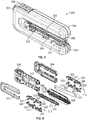
- FIGS. 5 and 6 illustrate an alternate buttress applicator (300) for use with end effector (40).
- Buttress applicator (300) comprises a first housing portion (302) and a second housing portion (304).
- Each of housing portions (302, 304) connects with a frame (306).
- a compression pad (308) is configured to fit within a central portion (310) of frame (306).
- a first pair of clamp arms (312) are located on a first side of frame (306) between frame (306) and housing portion (302).
- a second pair of clamp arms (314) are located on a second side of frame (306) between frame (306) and housing portion (304).
- clamp arms (312) comprise a left clamp arm (311) and a right clamp arm (313).
- clamp arms (314) comprise a left clamp arm (311) and a right clamp arm (313).
- Buttress assemblies (316, 318) are located on respective sides of compression pad (308), and when buttress applicator (300) is fully assembled, pairs of clamp arms (312, 314) selectively retain buttress assemblies (316, 318) against compression pad (308).
- buttress assemblies (316, 318) are the same with each comprising an adhesive (320) located on a buttress (322) as will be described in greater detail below.
- Buttress applicator (300) can be used with end effector (40) in the same manner as described above with respect to buttress applicator (200). For instance, buttress assemblies (316, 318) are loaded to end effector (40) in the same manner as described above where end effector (40) is moved to a closed or clamped position once anvil (60) and lower jaw (50) are positioned over central portion (310) of frame (308), e.g. as illustrated in FIG. 2 .
- end effector (40) when over buttress assemblies (316, 318) and compression pad (308) causes anvil (60) and staple cartridge (70) of lower jaw (50) to contact retention features (324) on left clamp arms (311) and retention features (325) on right clamp arms (313).
- This contact drives clamp arms (311, 313) laterally away from buttress assemblies (316, 318) thereby disengaging retention features (324, 325) from buttress assemblies (316, 318).
- buttress assembly (316) contacts either underside (65) of anvil (60) or deck (73) of staple cartridge (70), while adhesive (320) of buttress assembly (318) contacts the other of underside (65) of anvil (60) or deck (73) of staple cartridge (70).
- adhesive (320) of buttress assembly (318) contacts the other of underside (65) of anvil (60) or deck (73) of staple cartridge (70).
- buttress assemblies (316, 318) may attach with end effector (40) and remain with end effector (40) as end effector is opened and moved away from buttress applicator (300). From this point, buttress assemblies (316, 318) may be applied to a cut and staple tissue site as described above and illustrated with respect to FIG. 4 .
- FIGS. 7 and 8 illustrate buttress (322) of buttress assemblies (316, 318).
- Buttress (322) comprises a multi-layer material that is laminated together.
- buttress (322) comprises a mesh layer (326) and two film layers (332, 334).
- Mesh layer (326) comprises a knitted synthetic absorbable material.
- mesh layer (326) is knit using yarns (328) comprised of polyglactin 910, which is 90% glycolide and 10% L-lactide.
- polyglactin 910 is manufactured by Ethicon Inc. under the brand name Vicryl®.
- other absorbable synthetic materials for use with mesh layer (326) will be apparent to those of ordinary skill in the art.
- FIG. 8 illustrates an enlarged portion of mesh layer (326), showing an exemplary knit pattern produced by the arrangement of yarns (328).
- each yarn (328) comprises a bundle or structure having 28 individual filaments.
- each yarn (328) can comprise a single filament or a multifilament bundle with greater or fewer than 28 individual filaments.
- An example of the multifilament structures of mesh layer (326) can be seen in FIG. 10 , where the uncut yarns in cross section illustrate multiple filaments (329) that make up the multifilament structure of yarns (328).
- mesh layer (326) comprises a plurality of openings (330) defined by the knit yarns (328). With its openings (330) mesh layer (326) comprises a porosity. Depending on the number and/or size of openings (330) the porosity of mesh layer (326) can be changed with various mesh layers (326). Furthermore, the knit pattern as well as the yarn size can influence openings (330) and the resultant porosity. In the present example, plurality of openings (330) are configured in size and/or number such that they promote tissue ingrowth when one side of mesh layer (326) of buttress (322) is placed adjacent or in contact with tissue at a stapled site.
- buttress (322) comprises one or more tissue ingrowth features, which are configured to promote tissue ingrowth with buttress (322). Such tissue ingrowth can provide strength to the cut and stapled site and promote healing of the tissue.
- tissue ingrowth can provide strength to the cut and stapled site and promote healing of the tissue.
- buttress (322) also comprises a film layer (332).
- Film layer (332) is configured as an adhesive layer.
- film layer (332) is located on one side of mesh layer (326), and is configured to adhesively attach mesh layer (326) with film layer (334).
- Film layer (332) in the present example, comprises a polydioxanone (PDO) film; however, in other versions other types of film may be used and will be apparent to those of ordinary skill in the art in view of the teachings herein.
- film layer (332) is about 8 micrometers in thickness in the present example; however, in other versions the thickness of film layer (332) may be greater or less than 8 micrometers.
- the polydioxanone film can be included in the construct as a thin film either on its own at the time of lamination or coextruded onto film layer (334) prior to lamination to the mesh layer (326).
- film layer (332) is also in contact with film layer (334).
- Film layer (334) contacts film layer (332) on the side opposite to where film layer (332) contacts mesh layer (326).
- film layer (334) is configured as an adhesion barrier to prevent tissue adhesions from forming at or near the surgically stapled site.
- Film layer (334), in the present example is constructed of poliglecaprone 25.
- An example poliglecaprone 25 is manufactured by Ethicon Inc. under the brand name Moncryl®.
- film layer (334) is about 10 micrometers in thickness; however, in other versions the thickness of film layer (334) may be greater or less than 10 micrometers.
- Film layer (334) is also substantially continuous in the present example, and is configured to receive adhesive (320) as described above and as shown best in FIG. 9 .
- film layer (334) is on the side of buttress (322) that releasably attaches with end effector (40) when buttress assemblies (316, 318) are loaded to end effector (40) as described above.
- film layer (334) is positioned facing away from the stapled tissue site, whereas openings (330) of mesh layer (326) are positioned facing the stapled tissue site as mentioned above to promote tissue ingrowth.
- film layer (334) is illustrated as substantially continuous, with the exception of slits (336) described further below, in some other versions film layer (334) can include openings therein, for example as disclosed in U.S. Pat. No. 8,579,990 , entitled “Tissue Repair Devices of Rapid Therapeutic Absorbency,” issued November 12, 2013, and incorporated by reference herein.
- buttress (322) When constructing buttress (322), mesh layer (326) and film layers (332, 334) are laminated together to form the multi-layer material comprising buttress (322).
- the lamination occurs under elevated pressure and temperature. Buttress (322) is subjected to these conditions for a predetermined time to achieve acceptable lamination of the layers.
- buttress (322) is mechanically cut from a larger piece or fabric of multi-layer material having the same construction as described above for buttress (322). This mechanical cutting can be done at lower temperatures compared to other cutting applications, which allows for buttresses (322) to be cut from larger fabrics while avoiding charred or burnt edges that can occur with heated cutting techniques.
- buttresses (322) are mechanically cut out from the larger fabric such that the knit pattern is cut along a 45 degree angle relative to a longitudinal axis (LA) of buttress (322).
- LA longitudinal axis
- FIGS. 7 and 8 the knit pattern of mesh layer (326) is illustrated having been cut out at about 45 degrees relative to longitudinal axis (LA).
- axis (A1) illustrates the direction of the knit pattern of mesh layer (326).
- ⁇ which is approximately 45 degrees in the present example.
- buttress (322) also comprises multiple slits (336) that extend longitudinally along buttress (322). Slits (336) extend all the way through mesh layer (326), through film layer (332), and through film layer (334). Furthermore, slits (336) are positioned to generally divide buttress (332) into two equal sections. Referring to FIG. 4 , when buttress assemblies (316, 318) are used with end effector (40) in a cutting and stapling procedure, the knife (not shown) of the stapler will travel longitudinally down end effector (40) to cut clamped tissue and at the same time cut buttresses (322) of buttress assemblies (316, 318) along slits (336).
- Slits (336) act as precuts in buttress (332) such that during a cutting and stapling action, buttress (332) offers less resistance to being cut, which promotes buttress (332) remaining properly placed relative to the surgically cut and stapled site, instead of buttress (332) being pushed longitudinally by the cutting knife and bunching. While the present example uses slits (336) to precut and promote ease of cutting buttress (322), in view of the teachings herein, other techniques and precut geometries can be used and will be apparent to those of ordinary skill in the art.
- a buttress assembly for reinforcing tissue layers joined by surgical stapling, comprises (a) a multi-layer base material comprising (i) a mesh layer comprising a first mesh surface and a second mesh surface, wherein the first mesh surface is configured to contact the tissue joined by the surgical stapling, (ii) a first film layer contacting the second mesh surface of the mesh layer, wherein the first film layer is configured as an adhesive layer, and (iii) a second film layer comprising a first film surface and a second film surface, wherein first film surface contacts the first film layer, wherein the second film surface is configured to face away from the tissue joined by the surgical stapling; and (b) an adhesive located on the second film surface of the second film layer, wherein the adhesive is configured to provide releasable adhesion of the buttress assembly with an end effector of a surgical stapler.
- Example 1 The buttress assembly of Example 1, wherein the mesh layer comprises a knitted textile constructed from an absorbable synthetic material.
- a buttress configured for use with an end effector of a surgical stapler, is further configured for reinforcing a surgically stapled site.
- the buttress comprises (a) a mesh layer knitted from a multi-filament absorbable synthetic material, wherein the mesh layer defines a plurality of openings. On a first side of the mesh layer the plurality of openings are configured to face the surgically stapled site and contact tissue to promote tissue ingrowth.
- the buttress further comprises (b) a film layer located opposite to the first side of the mesh layer with the exposed plurality of openings, wherein the film layer is configured to face away from the surgically stapled site and prevent tissue adhesions at and around the surgically stapled site.
- Example 16 The buttress of Example 16, wherein the mesh layer comprises polyglactin 910, and wherein the film layer comprises poliglecaprone 25.
- a method of reinforcing tissue at a surgically stapled site comprises (a) positioning an end effector of a surgical stapler relative to a buttress applicator.
- the buttress applicator selectively retains a buttress comprising (i) a mesh layer knitted from a multi-filament absorbable synthetic material.
- the mesh layer defines a plurality of openings, wherein on a first side of the mesh layer the plurality of openings are configured to face the surgically stapled site and contact tissue to promote tissue ingrowth.
- the buttress further comprises (ii) a film layer located opposite to the first side of the mesh layer with the exposed plurality of openings. The film layer is configured to face away from the surgically stapled site and prevent tissue adhesions at and around the surgically stapled site.
- the method further comprises (b) clamping the end effector onto a portion of the buttress applicator, wherein the act of clamping causing disengagement of retention features of the buttress applicator from the buttress.
- the act of clamping further causes the buttress to releasably attach with the end effector via an adhesive located on the buttress.
- the method further comprises (c) separating the end effector from the buttress applicator, (d) positioning the end effector relative to the tissue to be surgically stapled, and (e) stapling the tissue.
- the act of stapling the tissue comprises applying the buttress to the surgically stapled site with the first side of the mesh layer facing the surgically stapled site, and with the film layer facing away from the surgically stapled site to act as an adhesion barrier.
- Example 19 The method of Example 19, further comprising prior to the buttress being loaded onto the buttress applicator, the buttress is mechanical cut from a larger piece, wherein the cutting avoids overheating the buttress, thereby preventing charred edges
- buttress and “buttress assembly” are used throughout this disclosure, it should be understood that the term is not intended to limit the scope of the present invention in any way. For instance, use of the terms “buttress” and “buttress assembly” is not intended to demonstrate contemplation that a “buttress” or “buttress assembly” can only be used to provide structural support to a staple line or serve any other particular purpose. It is contemplated that “buttress” or “buttress assembly” may serve a variety of purposes in addition to or as an alternative to providing structural support to a staple line. The terms “buttress” and “buttress assembly” should therefore be read broadly to include any kind of adjunct to a staple line that serves any suitable purpose.
- any of the various buttress assemblies described herein may be further constructed and operable in accordance with at least some of the teachings of U.S. Pat. Pub. No. 2016/0278774 , entitled “Method of Applying a Buttress to a Surgical Stapler,” published September 29, 2016, the disclosure of which is incorporated by reference herein; U.S. Pat. Pub. No. 2017/0049444 , entitled “Implantable Layers for a Surgical Instrument,” published February 23, 2017, the disclosure of which is incorporated by reference herein; U.S. Pat. Pub. No.
- Versions of the devices described above may have application in conventional medical treatments and procedures conducted by a medical professional, as well as application in robotic-assisted medical treatments and procedures.
- various teachings herein may be readily incorporated into a robotic surgical system such as the DAVINCITM system by Intuitive Surgical, Inc., of Sunnyvale, California.
- Versions of the devices described above may be designed to be disposed of after a single use, or they can be designed to be used multiple times. Versions may, in either or both cases, be reconditioned for reuse after at least one use. Reconditioning may include any combination of the steps of disassembly of the device, followed by cleaning or replacement of particular pieces, and subsequent reassembly. In particular, some versions of the device may be disassembled, and any number of the particular pieces or parts of the device may be selectively replaced or removed in any combination. Upon cleaning and/or replacement of particular parts, some versions of the device may be reassembled for subsequent use either at a reconditioning facility, or by a user immediately prior to a procedure.
- reconditioning of a device may utilize a variety of techniques for disassembly, cleaning/replacement, and reassembly. Use of such techniques, and the resulting reconditioned device, are all within the scope of the present application.
- versions described herein may be sterilized before and/or after a procedure.
- the device is placed in a closed and sealed container, such as a plastic or TYVEK bag.
- the container and device may then be placed in a field of radiation that can penetrate the container, such as gamma radiation, x-rays, or high-energy electrons.
- the radiation may kill bacteria on the device and in the container.
- the sterilized device may then be stored in the sterile container for later use.
- a device may also be sterilized using any other technique known in the art, including but not limited to beta or gamma radiation, ethylene oxide, or steam.
Landscapes
- Health & Medical Sciences (AREA)
- Surgery (AREA)
- Life Sciences & Earth Sciences (AREA)
- Animal Behavior & Ethology (AREA)
- Veterinary Medicine (AREA)
- Public Health (AREA)
- Heart & Thoracic Surgery (AREA)
- General Health & Medical Sciences (AREA)
- Engineering & Computer Science (AREA)
- Molecular Biology (AREA)
- Medical Informatics (AREA)
- Biomedical Technology (AREA)
- Nuclear Medicine, Radiotherapy & Molecular Imaging (AREA)
- Chemical & Material Sciences (AREA)
- Chemical Kinetics & Catalysis (AREA)
- Vascular Medicine (AREA)
- Epidemiology (AREA)
- Surgical Instruments (AREA)
- Materials For Medical Uses (AREA)
Applications Claiming Priority (1)
| Application Number | Priority Date | Filing Date | Title |
|---|---|---|---|
| US16/235,503 US20200205822A1 (en) | 2018-12-28 | 2018-12-28 | Surgical stapler buttress with tissue in-growth promotion |
Publications (1)
| Publication Number | Publication Date |
|---|---|
| EP3673820A1 true EP3673820A1 (de) | 2020-07-01 |
Family
ID=69159813
Family Applications (1)
| Application Number | Title | Priority Date | Filing Date |
|---|---|---|---|
| EP19218567.6A Withdrawn EP3673820A1 (de) | 2018-12-28 | 2019-12-20 | Chirurgisches klammerwiderlager mit gewebewachstumsförderung |
Country Status (6)
| Country | Link |
|---|---|
| US (1) | US20200205822A1 (de) |
| EP (1) | EP3673820A1 (de) |
| JP (1) | JP2022516717A (de) |
| CN (1) | CN113260318B (de) |
| BR (1) | BR112021012603A2 (de) |
| WO (1) | WO2020136490A1 (de) |
Families Citing this family (10)
| Publication number | Priority date | Publication date | Assignee | Title |
|---|---|---|---|---|
| US10542981B2 (en) | 2016-11-14 | 2020-01-28 | Ethicon Llc | Atraumatic stapling head features for circular surgical stapler |
| US11701109B2 (en) | 2018-12-28 | 2023-07-18 | Cilag Gmbh International | Surgical stapler with sloped staple deck for varying tissue compression |
| US11202628B2 (en) | 2018-12-28 | 2021-12-21 | Cilag Gmbh International | Surgical stapler with tissue engagement features around tissue containment pin |
| USD926317S1 (en) | 2018-12-28 | 2021-07-27 | Cilag Gmbh International | Surgical stapler deck with tissue engagement cleat features |
| USD901686S1 (en) | 2018-12-28 | 2020-11-10 | Ethicon Llc | Applicator for surgical stapler buttress |
| US11432817B2 (en) | 2018-12-28 | 2022-09-06 | Cilag Gmbh International | Packaging for surgical stapler buttress |
| US11033269B2 (en) | 2018-12-28 | 2021-06-15 | Cilag Gmbh International | Method of applying buttresses to surgically cut and stapled sites |
| USD926318S1 (en) | 2018-12-28 | 2021-07-27 | Cilag Gmbh International | Surgical stapler deck with tissue engagement recess features |
| US11707279B2 (en) * | 2020-11-25 | 2023-07-25 | Cilag Gmbh International | Compressible knitted adjuncts with finished edges |
| US11806017B2 (en) * | 2021-11-23 | 2023-11-07 | Covidien Lp | Anvil buttress loading system for surgical stapling apparatus |
Citations (49)
| Publication number | Priority date | Publication date | Assignee | Title |
|---|---|---|---|---|
| US4805823A (en) | 1988-03-18 | 1989-02-21 | Ethicon, Inc. | Pocket configuration for internal organ staplers |
| US5415334A (en) | 1993-05-05 | 1995-05-16 | Ethicon Endo-Surgery | Surgical stapler and staple cartridge |
| US5465895A (en) | 1994-02-03 | 1995-11-14 | Ethicon Endo-Surgery, Inc. | Surgical stapler instrument |
| US5597107A (en) | 1994-02-03 | 1997-01-28 | Ethicon Endo-Surgery, Inc. | Surgical stapler instrument |
| US5632432A (en) | 1994-12-19 | 1997-05-27 | Ethicon Endo-Surgery, Inc. | Surgical instrument |
| US5704534A (en) | 1994-12-19 | 1998-01-06 | Ethicon Endo-Surgery, Inc. | Articulation assembly for surgical instruments |
| US5814055A (en) | 1995-09-19 | 1998-09-29 | Ethicon Endo-Surgery, Inc. | Surgical clamping mechanism |
| US6978921B2 (en) | 2003-05-20 | 2005-12-27 | Ethicon Endo-Surgery, Inc. | Surgical stapling instrument incorporating an E-beam firing mechanism |
| US7143923B2 (en) | 2003-05-20 | 2006-12-05 | Ethicon Endo-Surgery, Inc. | Surgical stapling instrument having a firing lockout for an unclosed anvil |
| US7303108B2 (en) | 2003-09-29 | 2007-12-04 | Ethicon Endo-Surgery, Inc. | Surgical stapling instrument incorporating a multi-stroke firing mechanism with a flexible rack |
| US7367485B2 (en) | 2004-06-30 | 2008-05-06 | Ethicon Endo-Surgery, Inc. | Surgical stapling instrument incorporating a multistroke firing mechanism having a rotary transmission |
| US7380695B2 (en) | 2003-05-20 | 2008-06-03 | Ethicon Endo-Surgery, Inc. | Surgical stapling instrument having a single lockout mechanism for prevention of firing |
| US7380696B2 (en) | 2003-05-20 | 2008-06-03 | Ethicon Endo-Surgery, Inc. | Articulating surgical stapling instrument incorporating a two-piece E-beam firing mechanism |
| US20080169328A1 (en) | 2007-01-11 | 2008-07-17 | Shelton Frederick E | Buttress material for use with a surgical stapler |
| US7404508B2 (en) | 2005-07-26 | 2008-07-29 | Ethicon Endo-Surgery, Inc. | Surgical stapling and cutting device |
| US7434715B2 (en) | 2003-09-29 | 2008-10-14 | Ethicon Endo-Surgery, Inc. | Surgical stapling instrument having multistroke firing with opening lockout |
| EP2008595A2 (de) * | 2007-06-27 | 2008-12-31 | Tyco Healthcare Group LP | Versteifung und chirurgisches Klammergerät |
| US7721930B2 (en) | 2006-11-10 | 2010-05-25 | Thicon Endo-Surgery, Inc. | Disposable cartridge with adhesive for use with a stapling device |
| US8141762B2 (en) | 2009-10-09 | 2012-03-27 | Ethicon Endo-Surgery, Inc. | Surgical stapler comprising a staple pocket |
| US8371491B2 (en) | 2008-02-15 | 2013-02-12 | Ethicon Endo-Surgery, Inc. | Surgical end effector having buttress retention features |
| US8408439B2 (en) | 2007-06-22 | 2013-04-02 | Ethicon Endo-Surgery, Inc. | Surgical stapling instrument with an articulatable end effector |
| US8453914B2 (en) | 2009-12-24 | 2013-06-04 | Ethicon Endo-Surgery, Inc. | Motor-driven surgical cutting instrument with electric actuator directional control assembly |
| US20130206813A1 (en) | 2012-02-14 | 2013-08-15 | Ethicon Endo-Surgery, Inc. | Linear stapler |
| US8579990B2 (en) | 2011-03-30 | 2013-11-12 | Ethicon, Inc. | Tissue repair devices of rapid therapeutic absorbency |
| US8801735B2 (en) | 2010-07-30 | 2014-08-12 | Ethicon Endo-Surgery, Inc. | Surgical circular stapler with tissue retention arrangements |
| US9186142B2 (en) | 2013-02-28 | 2015-11-17 | Ethicon Endo-Surgery, Inc. | Surgical instrument end effector articulation drive with pinion and opposing racks |
| US20160089146A1 (en) | 2014-09-26 | 2016-03-31 | Ethicon Endo-Surgery, Inc. | Circular fastener cartridges for applying radially expandable fastener lines |
| US9398911B2 (en) | 2013-03-01 | 2016-07-26 | Ethicon Endo-Surgery, Llc | Rotary powered surgical instruments with multiple degrees of freedom |
| EP3072460A2 (de) * | 2015-03-25 | 2016-09-28 | Ethicon Endo-Surgery, LLC | Verfahren zum aufbringen einer versteifung auf einem chirurgischen klammergerät |
| US9517065B2 (en) | 2013-02-28 | 2016-12-13 | Ethicon Endo-Surgery, Llc | Integrated tissue positioning and jaw alignment features for surgical stapler |
| US20170049444A1 (en) | 2015-08-17 | 2017-02-23 | Ethicon Endo-Surgery, Llc | Implantable layers for a surgical instrument |
| US20170055981A1 (en) | 2015-08-24 | 2017-03-02 | Ethicon Endo-Surgery, Llc | Method of applying a buttress to a surgical stapler end effector |
| US20170056018A1 (en) | 2015-08-24 | 2017-03-02 | Ethicon Endo-Surgery, Llc | Surgical stapler buttress applicator with state indicator |
| US20170055980A1 (en) | 2015-08-24 | 2017-03-02 | Ethicon Endo-Surgery, Llc | Surgical stapler buttress applicator with spent staple cartridge lockout |
| US20170056016A1 (en) | 2015-08-24 | 2017-03-02 | Ethicon Endo-Surgery, Llc | Surgical stapler buttress applicator with end effector actuated release mechanism |
| US20170056017A1 (en) | 2015-08-24 | 2017-03-02 | Ethicon Endo-Surgery, Llc | Surgical stapler buttress applicator with multi-zone platform for pressure focused release |
| US20170055982A1 (en) | 2015-08-24 | 2017-03-02 | Ethicon Endo-Surgery, Llc | Surgical stapler buttress applicator with multi-point actuated release mechanism |
| US9597082B2 (en) | 2013-03-14 | 2017-03-21 | Ethicon Endo-Surgery, Llc | Method and apparatus for sealing end-to-end anastomosis |
| US20170086837A1 (en) | 2015-09-30 | 2017-03-30 | Ethicon Endo-Surgey, LLC | Compressible adjunct with crossing spacer fibers |
| US20170086842A1 (en) | 2015-09-30 | 2017-03-30 | Ethicon Endo-Surgery, Llc | Method for applying an implantable layer to a fastener cartridge |
| US9622746B2 (en) | 2013-02-28 | 2017-04-18 | Ethicon Endo-Surgery, Llc | Distal tip features for end effector of surgical instrument |
| US9717497B2 (en) | 2013-02-28 | 2017-08-01 | Ethicon Llc | Lockout feature for movable cutting member of surgical instrument |
| US9795379B2 (en) | 2013-02-28 | 2017-10-24 | Ethicon Llc | Surgical instrument with multi-diameter shaft |
| US9808248B2 (en) | 2013-02-28 | 2017-11-07 | Ethicon Llc | Installation features for surgical instrument end effector cartridge |
| US9839421B2 (en) | 2013-02-28 | 2017-12-12 | Ethicon Llc | Jaw closure feature for end effector of surgical instrument |
| US9848871B2 (en) | 2014-06-10 | 2017-12-26 | Ethicon Llc | Woven and fibrous materials for reinforcing a staple line |
| US9867615B2 (en) | 2013-02-28 | 2018-01-16 | Ethicon Llc | Surgical instrument with articulation lock having a detenting binary spring |
| US9936954B2 (en) | 2014-06-10 | 2018-04-10 | Ethicon Llc | Devices and methods for sealing staples in tissue |
| US10092292B2 (en) | 2013-02-28 | 2018-10-09 | Ethicon Llc | Staple forming features for surgical stapling instrument |
Family Cites Families (4)
| Publication number | Priority date | Publication date | Assignee | Title |
|---|---|---|---|---|
| US10085745B2 (en) * | 2015-10-29 | 2018-10-02 | Ethicon Llc | Extensible buttress assembly for surgical stapler |
| US10314588B2 (en) * | 2015-10-29 | 2019-06-11 | Ethicon Llc | Fluid penetrable buttress assembly for a surgical stapler |
| US10357248B2 (en) * | 2015-10-29 | 2019-07-23 | Ethicon Llc | Extensible buttress assembly for surgical stapler |
| US10499918B2 (en) * | 2015-10-29 | 2019-12-10 | Ethicon Llc | Surgical stapler buttress assembly with features to interact with movable end effector components |
-
2018
- 2018-12-28 US US16/235,503 patent/US20200205822A1/en not_active Abandoned
-
2019
- 2019-12-16 WO PCT/IB2019/060818 patent/WO2020136490A1/en not_active Ceased
- 2019-12-16 CN CN201980086495.5A patent/CN113260318B/zh active Active
- 2019-12-16 JP JP2021537815A patent/JP2022516717A/ja active Pending
- 2019-12-16 BR BR112021012603-1A patent/BR112021012603A2/pt not_active IP Right Cessation
- 2019-12-20 EP EP19218567.6A patent/EP3673820A1/de not_active Withdrawn
Patent Citations (52)
| Publication number | Priority date | Publication date | Assignee | Title |
|---|---|---|---|---|
| US4805823A (en) | 1988-03-18 | 1989-02-21 | Ethicon, Inc. | Pocket configuration for internal organ staplers |
| US5415334A (en) | 1993-05-05 | 1995-05-16 | Ethicon Endo-Surgery | Surgical stapler and staple cartridge |
| US5465895A (en) | 1994-02-03 | 1995-11-14 | Ethicon Endo-Surgery, Inc. | Surgical stapler instrument |
| US5597107A (en) | 1994-02-03 | 1997-01-28 | Ethicon Endo-Surgery, Inc. | Surgical stapler instrument |
| US5704534A (en) | 1994-12-19 | 1998-01-06 | Ethicon Endo-Surgery, Inc. | Articulation assembly for surgical instruments |
| US5673840A (en) | 1994-12-19 | 1997-10-07 | Ethicon Endo-Surgery, Inc. | Surgical instrument |
| US5632432A (en) | 1994-12-19 | 1997-05-27 | Ethicon Endo-Surgery, Inc. | Surgical instrument |
| US5814055A (en) | 1995-09-19 | 1998-09-29 | Ethicon Endo-Surgery, Inc. | Surgical clamping mechanism |
| US6978921B2 (en) | 2003-05-20 | 2005-12-27 | Ethicon Endo-Surgery, Inc. | Surgical stapling instrument incorporating an E-beam firing mechanism |
| US7000818B2 (en) | 2003-05-20 | 2006-02-21 | Ethicon, Endo-Surger, Inc. | Surgical stapling instrument having separate distinct closing and firing systems |
| US7143923B2 (en) | 2003-05-20 | 2006-12-05 | Ethicon Endo-Surgery, Inc. | Surgical stapling instrument having a firing lockout for an unclosed anvil |
| US7380695B2 (en) | 2003-05-20 | 2008-06-03 | Ethicon Endo-Surgery, Inc. | Surgical stapling instrument having a single lockout mechanism for prevention of firing |
| US7380696B2 (en) | 2003-05-20 | 2008-06-03 | Ethicon Endo-Surgery, Inc. | Articulating surgical stapling instrument incorporating a two-piece E-beam firing mechanism |
| US7434715B2 (en) | 2003-09-29 | 2008-10-14 | Ethicon Endo-Surgery, Inc. | Surgical stapling instrument having multistroke firing with opening lockout |
| US7303108B2 (en) | 2003-09-29 | 2007-12-04 | Ethicon Endo-Surgery, Inc. | Surgical stapling instrument incorporating a multi-stroke firing mechanism with a flexible rack |
| US7367485B2 (en) | 2004-06-30 | 2008-05-06 | Ethicon Endo-Surgery, Inc. | Surgical stapling instrument incorporating a multistroke firing mechanism having a rotary transmission |
| US7404508B2 (en) | 2005-07-26 | 2008-07-29 | Ethicon Endo-Surgery, Inc. | Surgical stapling and cutting device |
| US7721930B2 (en) | 2006-11-10 | 2010-05-25 | Thicon Endo-Surgery, Inc. | Disposable cartridge with adhesive for use with a stapling device |
| US20080169328A1 (en) | 2007-01-11 | 2008-07-17 | Shelton Frederick E | Buttress material for use with a surgical stapler |
| US8408439B2 (en) | 2007-06-22 | 2013-04-02 | Ethicon Endo-Surgery, Inc. | Surgical stapling instrument with an articulatable end effector |
| EP2008595A2 (de) * | 2007-06-27 | 2008-12-31 | Tyco Healthcare Group LP | Versteifung und chirurgisches Klammergerät |
| US8371491B2 (en) | 2008-02-15 | 2013-02-12 | Ethicon Endo-Surgery, Inc. | Surgical end effector having buttress retention features |
| US8141762B2 (en) | 2009-10-09 | 2012-03-27 | Ethicon Endo-Surgery, Inc. | Surgical stapler comprising a staple pocket |
| US8453914B2 (en) | 2009-12-24 | 2013-06-04 | Ethicon Endo-Surgery, Inc. | Motor-driven surgical cutting instrument with electric actuator directional control assembly |
| US8801735B2 (en) | 2010-07-30 | 2014-08-12 | Ethicon Endo-Surgery, Inc. | Surgical circular stapler with tissue retention arrangements |
| US8579990B2 (en) | 2011-03-30 | 2013-11-12 | Ethicon, Inc. | Tissue repair devices of rapid therapeutic absorbency |
| US20130206813A1 (en) | 2012-02-14 | 2013-08-15 | Ethicon Endo-Surgery, Inc. | Linear stapler |
| US9717497B2 (en) | 2013-02-28 | 2017-08-01 | Ethicon Llc | Lockout feature for movable cutting member of surgical instrument |
| US9622746B2 (en) | 2013-02-28 | 2017-04-18 | Ethicon Endo-Surgery, Llc | Distal tip features for end effector of surgical instrument |
| US10092292B2 (en) | 2013-02-28 | 2018-10-09 | Ethicon Llc | Staple forming features for surgical stapling instrument |
| US9867615B2 (en) | 2013-02-28 | 2018-01-16 | Ethicon Llc | Surgical instrument with articulation lock having a detenting binary spring |
| US9517065B2 (en) | 2013-02-28 | 2016-12-13 | Ethicon Endo-Surgery, Llc | Integrated tissue positioning and jaw alignment features for surgical stapler |
| US9839421B2 (en) | 2013-02-28 | 2017-12-12 | Ethicon Llc | Jaw closure feature for end effector of surgical instrument |
| US9808248B2 (en) | 2013-02-28 | 2017-11-07 | Ethicon Llc | Installation features for surgical instrument end effector cartridge |
| US9795379B2 (en) | 2013-02-28 | 2017-10-24 | Ethicon Llc | Surgical instrument with multi-diameter shaft |
| US9186142B2 (en) | 2013-02-28 | 2015-11-17 | Ethicon Endo-Surgery, Inc. | Surgical instrument end effector articulation drive with pinion and opposing racks |
| US9398911B2 (en) | 2013-03-01 | 2016-07-26 | Ethicon Endo-Surgery, Llc | Rotary powered surgical instruments with multiple degrees of freedom |
| US9597082B2 (en) | 2013-03-14 | 2017-03-21 | Ethicon Endo-Surgery, Llc | Method and apparatus for sealing end-to-end anastomosis |
| US9848871B2 (en) | 2014-06-10 | 2017-12-26 | Ethicon Llc | Woven and fibrous materials for reinforcing a staple line |
| US9936954B2 (en) | 2014-06-10 | 2018-04-10 | Ethicon Llc | Devices and methods for sealing staples in tissue |
| US20160089146A1 (en) | 2014-09-26 | 2016-03-31 | Ethicon Endo-Surgery, Inc. | Circular fastener cartridges for applying radially expandable fastener lines |
| EP3072460A2 (de) * | 2015-03-25 | 2016-09-28 | Ethicon Endo-Surgery, LLC | Verfahren zum aufbringen einer versteifung auf einem chirurgischen klammergerät |
| US20160278774A1 (en) | 2015-03-25 | 2016-09-29 | Ethicon Endo-Surgery, Llc | Method of applying a buttress to a surgical stapler |
| US20170049444A1 (en) | 2015-08-17 | 2017-02-23 | Ethicon Endo-Surgery, Llc | Implantable layers for a surgical instrument |
| US20170055980A1 (en) | 2015-08-24 | 2017-03-02 | Ethicon Endo-Surgery, Llc | Surgical stapler buttress applicator with spent staple cartridge lockout |
| US20170056016A1 (en) | 2015-08-24 | 2017-03-02 | Ethicon Endo-Surgery, Llc | Surgical stapler buttress applicator with end effector actuated release mechanism |
| US20170056018A1 (en) | 2015-08-24 | 2017-03-02 | Ethicon Endo-Surgery, Llc | Surgical stapler buttress applicator with state indicator |
| US20170055981A1 (en) | 2015-08-24 | 2017-03-02 | Ethicon Endo-Surgery, Llc | Method of applying a buttress to a surgical stapler end effector |
| US20170056017A1 (en) | 2015-08-24 | 2017-03-02 | Ethicon Endo-Surgery, Llc | Surgical stapler buttress applicator with multi-zone platform for pressure focused release |
| US20170055982A1 (en) | 2015-08-24 | 2017-03-02 | Ethicon Endo-Surgery, Llc | Surgical stapler buttress applicator with multi-point actuated release mechanism |
| US20170086842A1 (en) | 2015-09-30 | 2017-03-30 | Ethicon Endo-Surgery, Llc | Method for applying an implantable layer to a fastener cartridge |
| US20170086837A1 (en) | 2015-09-30 | 2017-03-30 | Ethicon Endo-Surgey, LLC | Compressible adjunct with crossing spacer fibers |
Also Published As
| Publication number | Publication date |
|---|---|
| CN113260318A (zh) | 2021-08-13 |
| US20200205822A1 (en) | 2020-07-02 |
| BR112021012603A2 (pt) | 2021-09-08 |
| JP2022516717A (ja) | 2022-03-02 |
| CN113260318B (zh) | 2024-07-05 |
| WO2020136490A1 (en) | 2020-07-02 |
Similar Documents
| Publication | Publication Date | Title |
|---|---|---|
| CN113260318B (zh) | 促进组织向内生长的外科缝合器支撑物 | |
| US10314588B2 (en) | Fluid penetrable buttress assembly for a surgical stapler | |
| US11166724B2 (en) | Adhesive distribution on buttress for surgical stapler | |
| US11116505B2 (en) | Applicator for surgical stapler buttress | |
| US10499918B2 (en) | Surgical stapler buttress assembly with features to interact with movable end effector components | |
| US10357248B2 (en) | Extensible buttress assembly for surgical stapler | |
| US10639039B2 (en) | Surgical stapler buttress applicator with multi-zone platform for pressure focused release | |
| JP7571025B2 (ja) | 外科用ステープラ用バットレスの構成 | |
| US20170056016A1 (en) | Surgical stapler buttress applicator with end effector actuated release mechanism |
Legal Events
| Date | Code | Title | Description |
|---|---|---|---|
| PUAI | Public reference made under article 153(3) epc to a published international application that has entered the european phase |
Free format text: ORIGINAL CODE: 0009012 |
|
| STAA | Information on the status of an ep patent application or granted ep patent |
Free format text: STATUS: THE APPLICATION HAS BEEN PUBLISHED |
|
| AK | Designated contracting states |
Kind code of ref document: A1 Designated state(s): AL AT BE BG CH CY CZ DE DK EE ES FI FR GB GR HR HU IE IS IT LI LT LU LV MC MK MT NL NO PL PT RO RS SE SI SK SM TR |
|
| AX | Request for extension of the european patent |
Extension state: BA ME |
|
| STAA | Information on the status of an ep patent application or granted ep patent |
Free format text: STATUS: REQUEST FOR EXAMINATION WAS MADE |
|
| 17P | Request for examination filed |
Effective date: 20201218 |
|
| RBV | Designated contracting states (corrected) |
Designated state(s): AL AT BE BG CH CY CZ DE DK EE ES FI FR GB GR HR HU IE IS IT LI LT LU LV MC MK MT NL NO PL PT RO RS SE SI SK SM TR |
|
| STAA | Information on the status of an ep patent application or granted ep patent |
Free format text: STATUS: EXAMINATION IS IN PROGRESS |
|
| 17Q | First examination report despatched |
Effective date: 20230329 |
|
| STAA | Information on the status of an ep patent application or granted ep patent |
Free format text: STATUS: THE APPLICATION HAS BEEN WITHDRAWN |
|
| 18W | Application withdrawn |
Effective date: 20230720 |