EP3673832A1 - Kartuschenaufnahmebacke für chirurgische klammervorrichtung und zugehöriges herstellungsverfahren mit stanzteil - Google Patents
Kartuschenaufnahmebacke für chirurgische klammervorrichtung und zugehöriges herstellungsverfahren mit stanzteil Download PDFInfo
- Publication number
- EP3673832A1 EP3673832A1 EP19220072.3A EP19220072A EP3673832A1 EP 3673832 A1 EP3673832 A1 EP 3673832A1 EP 19220072 A EP19220072 A EP 19220072A EP 3673832 A1 EP3673832 A1 EP 3673832A1
- Authority
- EP
- European Patent Office
- Prior art keywords
- lower jaw
- feature
- machined
- side wall
- distal
- Prior art date
- Legal status (The legal status is an assumption and is not a legal conclusion. Google has not performed a legal analysis and makes no representation as to the accuracy of the status listed.)
- Granted
Links
Images


Classifications
-
- A—HUMAN NECESSITIES
- A61—MEDICAL OR VETERINARY SCIENCE; HYGIENE
- A61B—DIAGNOSIS; SURGERY; IDENTIFICATION
- A61B17/00—Surgical instruments, devices or methods
- A61B17/068—Surgical staplers, e.g. containing multiple staples or clamps
- A61B17/072—Surgical staplers, e.g. containing multiple staples or clamps for applying a row of staples in a single action, e.g. the staples being applied simultaneously
- A61B17/07207—Surgical staplers, e.g. containing multiple staples or clamps for applying a row of staples in a single action, e.g. the staples being applied simultaneously the staples being applied sequentially
-
- B—PERFORMING OPERATIONS; TRANSPORTING
- B21—MECHANICAL METAL-WORKING WITHOUT ESSENTIALLY REMOVING MATERIAL; PUNCHING METAL
- B21D—WORKING OR PROCESSING OF SHEET METAL OR METAL TUBES, RODS OR PROFILES WITHOUT ESSENTIALLY REMOVING MATERIAL; PUNCHING METAL
- B21D53/00—Making other particular articles
-
- B—PERFORMING OPERATIONS; TRANSPORTING
- B21—MECHANICAL METAL-WORKING WITHOUT ESSENTIALLY REMOVING MATERIAL; PUNCHING METAL
- B21K—MAKING FORGED OR PRESSED METAL PRODUCTS, e.g. HORSE-SHOES, RIVETS, BOLTS OR WHEELS
- B21K5/00—Making tools or tool parts, e.g. pliers
- B21K5/12—Making tools or tool parts, e.g. pliers other cutting tools
-
- B—PERFORMING OPERATIONS; TRANSPORTING
- B23—MACHINE TOOLS; METAL-WORKING NOT OTHERWISE PROVIDED FOR
- B23P—METAL-WORKING NOT OTHERWISE PROVIDED FOR; COMBINED OPERATIONS; UNIVERSAL MACHINE TOOLS
- B23P15/00—Making specific metal objects by operations not covered by a single other subclass or a group in this subclass
-
- A—HUMAN NECESSITIES
- A61—MEDICAL OR VETERINARY SCIENCE; HYGIENE
- A61B—DIAGNOSIS; SURGERY; IDENTIFICATION
- A61B17/00—Surgical instruments, devices or methods
- A61B2017/00526—Methods of manufacturing
-
- A—HUMAN NECESSITIES
- A61—MEDICAL OR VETERINARY SCIENCE; HYGIENE
- A61B—DIAGNOSIS; SURGERY; IDENTIFICATION
- A61B17/00—Surgical instruments, devices or methods
- A61B17/068—Surgical staplers, e.g. containing multiple staples or clamps
- A61B17/072—Surgical staplers, e.g. containing multiple staples or clamps for applying a row of staples in a single action, e.g. the staples being applied simultaneously
- A61B2017/07214—Stapler heads
- A61B2017/07257—Stapler heads characterised by its anvil
- A61B2017/07264—Stapler heads characterised by its anvil characterised by its staple forming cavities, e.g. geometry or material
-
- A—HUMAN NECESSITIES
- A61—MEDICAL OR VETERINARY SCIENCE; HYGIENE
- A61B—DIAGNOSIS; SURGERY; IDENTIFICATION
- A61B17/00—Surgical instruments, devices or methods
- A61B17/068—Surgical staplers, e.g. containing multiple staples or clamps
- A61B17/072—Surgical staplers, e.g. containing multiple staples or clamps for applying a row of staples in a single action, e.g. the staples being applied simultaneously
- A61B2017/07214—Stapler heads
- A61B2017/07271—Stapler heads characterised by its cartridge
-
- A—HUMAN NECESSITIES
- A61—MEDICAL OR VETERINARY SCIENCE; HYGIENE
- A61B—DIAGNOSIS; SURGERY; IDENTIFICATION
- A61B17/00—Surgical instruments, devices or methods
- A61B17/068—Surgical staplers, e.g. containing multiple staples or clamps
- A61B17/072—Surgical staplers, e.g. containing multiple staples or clamps for applying a row of staples in a single action, e.g. the staples being applied simultaneously
- A61B2017/07214—Stapler heads
- A61B2017/07278—Stapler heads characterised by its sled or its staple holder
-
- A—HUMAN NECESSITIES
- A61—MEDICAL OR VETERINARY SCIENCE; HYGIENE
- A61B—DIAGNOSIS; SURGERY; IDENTIFICATION
- A61B17/00—Surgical instruments, devices or methods
- A61B17/068—Surgical staplers, e.g. containing multiple staples or clamps
- A61B17/072—Surgical staplers, e.g. containing multiple staples or clamps for applying a row of staples in a single action, e.g. the staples being applied simultaneously
- A61B2017/07214—Stapler heads
- A61B2017/07285—Stapler heads characterised by its cutter
-
- A—HUMAN NECESSITIES
- A61—MEDICAL OR VETERINARY SCIENCE; HYGIENE
- A61B—DIAGNOSIS; SURGERY; IDENTIFICATION
- A61B17/00—Surgical instruments, devices or methods
- A61B17/28—Surgical forceps
- A61B17/29—Forceps for use in minimally invasive surgery
- A61B2017/2926—Details of heads or jaws
- A61B2017/2927—Details of heads or jaws the angular position of the head being adjustable with respect to the shaft
-
- B—PERFORMING OPERATIONS; TRANSPORTING
- B21—MECHANICAL METAL-WORKING WITHOUT ESSENTIALLY REMOVING MATERIAL; PUNCHING METAL
- B21D—WORKING OR PROCESSING OF SHEET METAL OR METAL TUBES, RODS OR PROFILES WITHOUT ESSENTIALLY REMOVING MATERIAL; PUNCHING METAL
- B21D22/00—Shaping without cutting, by stamping, spinning, or deep-drawing
- B21D22/02—Stamping using rigid devices or tools
Definitions
- Endoscopic surgical instruments may include a shaft between the end effector and a handle portion, which is manipulated by the clinician.
- a shaft may enable insertion through a trocar to a desired depth and rotation about the longitudinal axis of the shaft, thereby facilitating positioning of the end effector within the patient.
- Positioning of an end effector may be further facilitated through inclusion of one or more articulation joints or features, enabling the end effector to be selectively articulated or otherwise deflected relative to the longitudinal axis of the shaft.
- endoscopic surgical instruments include surgical staplers. Some such staplers are operable to clamp down on layers of tissue, cut through the clamped layers of tissue, and drive staples through the layers of tissue to substantially seal the severed layers of tissue together near the severed ends of the tissue layers.
- surgical staplers are disclosed in U.S. Pat. No. 7,380,696 , entitled “Articulating Surgical Stapling Instrument Incorporating a Two-Piece E-Beam Firing Mechanism," issued June 3, 2008; U.S. Pat. No. 8,408,439 , entitled “Surgical Stapling Instrument with An Articulatable End Effector,” issued April 2, 2013; and U.S. Pat. No.
- Surgical staplers may also be used in open procedures and/or other non-endoscopic procedures.
- a surgical stapler may be inserted through a thoracotomy and thereby between a patient's ribs to reach one or more organs in a thoracic surgical procedure that does not use a trocar as a conduit for the stapler.
- the vessels leading to an organ may be severed and closed by a stapler before removal of the organ from the thoracic cavity.
- surgical staplers may be used in various other settings and procedures.
- proximal and distal are defined herein relative to a human or robotic operator of the surgical instrument.
- proximal refers the position of an element closer to the human or robotic operator of the surgical instrument and further away from the surgical end effector of the surgical instrument.
- distal refers to the position of an element closer to the surgical end effector of the surgical instrument and further away from the human or robotic operator of the surgical instrument.
- upper,” “lower,” “lateral,” “transverse,” “bottom,” “top,” are relative terms to provide additional clarity to the figure descriptions provided below. The terms “upper,” “lower,” “lateral,” “transverse,” “bottom,” “top,” are thus not intended to unnecessarily limit the invention described herein.
- first and second are used herein to distinguish one or more portions of the surgical instrument.
- a first assembly and a second assembly may be alternatively and respectively described as a second assembly and a first assembly.
- first and second and other numerical designations are merely exemplary of such terminology and are not intended to unnecessarily limit the invention described herein.
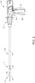
- FIGS. 1-6 depict a first exemplary surgical stapling and severing instrument (10) that is sized for insertion through a trocar cannula or an incision (e.g., thoracotomy, etc.) to a surgical site in a patient for performing a surgical procedure.
- Instrument (10) of the present example includes a handle portion (20) connected to a shaft (22), which distally terminates in an articulation joint (11), which is further coupled with a first exemplary end effector (12).
- Shaft (22) may be constructed in accordance with at least some of the teachings of U.S. Pat. No. 9,795,379 , entitled "Surgical Instrument with Multi-Diameter Shaft," issued October 24, 2017, the disclosure of which is incorporated by reference herein.
- articulation joint (11) and end effector (12) are inserted through the cannula passageway of a trocar, articulation joint (11) may be remotely articulated, as depicted in phantom in FIG. 1 , by an articulation control (13), such that end effector (12) may be deflected from the longitudinal axis (LA) of shaft (22) at a desired angle ( ⁇ ).
- Articulation joint (11) and/or articulation control (13) may be constructed and operable in accordance with at least some of the teachings of U.S. Pat. No.
- End effector (12) of the present example includes a lower jaw (16) and a pivotable anvil (18).
- Lower jaw (16) may be constructed in accordance with at least some of the teachings of U.S. Pat. No. 9,808,248 , entitled “Installation Features for Surgical Instrument End Effector Cartridge,” issued November 7, 2017, the disclosure of which is incorporated by reference herein.
- Anvil (18) may be constructed in accordance with at least some of the teachings of U.S. Pat. No. 9,517,065 , entitled “Integrated Tissue Positioning and Jaw Alignment Features for Surgical Stapler," issued December 13, 2016, the disclosure of which is incorporated by reference herein; U.S. Pat. No.
- Handle portion (20) includes a pistol grip (24) and a closure trigger (26).
- Closure trigger (26) is pivotable toward pistol grip (24) to cause clamping, or closing, of the anvil (18) toward lower jaw (16) of end effector (12).
- Such closing of anvil (18) is provided through a closure tube (32) and a closure ring (33), which both longitudinally translate relative to handle portion (20) in response to pivoting of closure trigger (26) relative to pistol grip (24).
- Closure tube (32) extends along the length of shaft (22); and closure ring (33) is positioned distal to articulation joint (11).
- Articulation joint (11) is operable to communicate/transmit longitudinal movement from closure tube (32) to closure ring (33).
- Handle portion (20) also includes a firing trigger (28) (shown in FIG.
- An elongate member (not shown) longitudinally extends through shaft (22) and communicates a longitudinal firing motion from handle portion (20) to a firing beam (14) in response to actuation of firing trigger (28). This distal translation of firing beam (14) causes the stapling and severing of clamped tissue in end effector (12), as will be described in greater detail below.
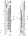
- FIGS. 3-6 depict end effector (12) employing an E-beam form of firing beam (14).
- firing beam (14) includes a transversely oriented upper pin (38), a firing beam cap (44), a transversely oriented middle pin (46), and a distally presented cutting edge (48).
- Upper pin (38) is positioned and translatable within a longitudinal anvil slot (42) of anvil (18).
- Firing beam cap (44) slidably engages a lower surface of lower jaw (16) by having firing beam (14) extend through lower jaw slot (45) (shown in FIG. 4B ) that is formed through lower jaw (16).
- Middle pin (46) slidingly engages a top surface of lower jaw (16), cooperating with firing beam cap (44).
- Firing beam (14) and/or associated lockout features may be constructed and operable in accordance with at least some of the teachings of U.S. Pat. No. 9,717,497 , entitled “Lockout Feature for Movable Cutting Member of Surgical Instrument,” issued August 1, 2017, the disclosure of which is incorporated by reference herein.
- FIG. 3 shows firing beam (14) of the present example proximally positioned and anvil (18) pivoted to an open position, allowing an unspent staple cartridge (37) to be removably installed into a channel of lower jaw (16).
- staple cartridge (37) of this example includes a cartridge body (70), which presents an upper deck (72) and is coupled with a lower cartridge tray (74).
- a vertical slot (49) is formed through part of staple cartridge (37).
- three rows of staple apertures (51) are formed through upper deck (72) on one side of vertical slot (49), with another set of three rows of staple apertures (51) being formed through upper deck (72) on the other side of vertical slot (49).
- a wedge sled (41) and a plurality of staple drivers (43) are captured between cartridge body (70) and cartridge tray (74), with wedge sled (41) being located proximal to staple drivers (43).
- Wedge sled (41) is movable longitudinally within staple cartridge (37); while staple drivers (43) are movable vertically within staple cartridge (37).
- Staples (47) are also positioned within cartridge body (70), above corresponding staple drivers (43). Each staple (47) is driven vertically within cartridge body (70) by a staple driver (43) to drive staple (47) out through an associated staple aperture (51).
- wedge sled (41) presents inclined cam surfaces that urge staple drivers (43) upwardly as wedge sled (41) is driven distally through staple cartridge (37).
- Staple cartridge (37) may be constructed and operable in accordance with at least some of the teachings of U.S. Pat. No. 9,517,065 , the disclosure of which is incorporated by reference herein; and/or U.S. Pat. No. 9,808,248 , the disclosure of which is incorporated by reference herein.
- firing beam (14) With end effector (12) closed as depicted in FIGS. 4A-4B by distally advancing closure tube (32) and closure ring (33), firing beam (14) is then advanced in engagement with anvil (18) by having upper pin (38) enter longitudinal anvil slot (42).
- a pusher block (80) (shown in FIG. 5 ) is located at the distal end of firing beam (14) and pushes wedge sled (41) as firing beam (14) is advanced distally through staple cartridge (37) when firing trigger (28) is actuated.
- cutting edge (48) of firing beam (14) enters vertical slot (49) of staple cartridge (37), severing tissue clamped between staple cartridge (37) and anvil (18).
- FIG. 4B depicts firing beam (14) fully distally translated after completing severing and stapling of tissue.
- Staple forming pockets (53) are intentionally omitted from the view in FIGS. 4A-4B ; but are shown in FIG. 3 .
- Anvil (18) is intentionally omitted from the view in FIG. 5 .
- anvil (18) pivots about an axis that is defined by a pin (or similar feature) that slides along an elongate slot or channel as anvil (18) moves toward lower jaw (16).
- the pivot axis translates along the path defined by the slot or channel while anvil (18) simultaneously pivots about that axis.
- Instrument (10) may otherwise be configured and operable in accordance with any of the teachings of any of the patent references cited herein. Additional exemplary modifications that may be provided for instrument (10) will be described in greater detail below.
- the below teachings are not limited to instrument (10) or devices taught in the patents cited herein.
- the below teachings may be readily applied to various other kinds of instruments, including instruments that would not be classified as surgical staplers.
- Various other suitable devices and settings in which the below teachings may be applied will be apparent to those of ordinary skill in the art in view of the teachings herein.
- lower jaw (16) of instrument (10) may be machined from a single solid block of material (e.g. metal).
- this machining of lower jaw (16) may be time consuming and expensive, both of which are undesirable.
- Conventional machining techniques, being reductive in nature, may also be considered as being inefficient since they may create waste in the material that is removed from the single solid block of material. Additionally, in some instances, considerable machining may impart undesirable stresses into lower jaw (16). As a result, it is desirable to manufacture lower jaw (16) using a faster, more efficient, and more cost-effective process or system of processes to further enhance lower jaw (16).
- lower jaw (16) may have tight tolerances to aid in the use of instrument (10), while other specific portions and features of lower jaw (16) may have looser tolerances where the precise dimensions are of lesser significance.
- lower jaw (210, 310) may be used in place of lower jaw (16) of instrument (10). Similar to the operation of instrument (10), where anvil (18) pivots relative to lower jaw (16), anvil (18) pivots relative to lower jaw (210, 310). As such, anvil (18) and lower jaw (210, 310) may clamp tissue similarly to the clamping performed by anvil (18) and lower jaw (16) shown in FIG. 1 . Similar to lower jaw (16), lower jaw (210, 310) is also configured to receive a staple cartridge, similar to staple cartridge (37) shown in FIG. 3 . Additional details of lower jaw (210, 310) are described below with reference to the following figures.
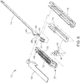
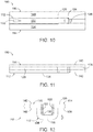
- FIGS. 7-12 show an exemplary lower jaw blank (110) that is configured to be transformed into a lower jaw (210, 310) shown in FIGS. 13-19B and FIGS. 20A-20B respectively, through one or more manufacturing processes as described below.
- Lower jaw (210, 310) is similar to lower jaw (16) of end effector (12), with notable differences indicated below.
- instrument (10) includes a body (shown as handle portion (20)), shaft (22) extending from the body, and end effector (12) in communication with shaft (22).
- End effector (12) is operable to compress, staple, and cut tissue.
- Lower jaw blank (110), once transformed into lower jaw (210, 310) is configured to be used in place of another lower jaw (e.g. lower jaw (16)) to form a portion of end effector (12).
- lower jaw blank (110) includes a U-shaped body portion (112) and outwardly extending flanges (114, 116) extending outwardly from U-shaped body portion (112).
- U-shaped body portion (112) includes a bottom wall (118) interposed between opposing side walls (120, 122).
- Side walls (120, 122) taper outwardly at outwardly tapering portions (124, 126).
- side walls (120, 122) do not include any apertures or cutouts at this manufacturing stage.
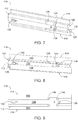
- FIGS. 9-12 show respective top, bottom, left side, and distal end views of lower jaw blank (110) prior to any features being formed into opposing side walls (120, 122).
- bottom wall (118) includes a proximal aperture (128) and a distal elongated aperture (130) that extend completely through inner and outer surfaces (132, 134) of bottom wall (118).
- side walls (120, 122) extend vertically at right angles from bottom wall (118), which is horizontally oriented. However, other angles between bottom wall (118) and side walls (120, 122) are also envisioned. More specifically, outwardly extending flange (114) extends from side wall (120) and includes opposing upper and lower planar surfaces (136, 138) shown in FIG. 12 . Similarly, outwardly extending flange (116) extends from side wall (122) and includes opposing upper and lower planar surfaces (140, 142). As shown in FIG. 12 , thickness (t) of lower jaw blank (110) is generally constant. However, thickness (t) may vary if desired. One or more stamping operations may be used to impart one or more additional features in bottom wall (118) and side walls (120, 122) as will be described in greater detail below.
- lower jaw blank (110) may be initially transformed from an initial flat planar sheet into U-shaped body portion (112) and outwardly extending flanges (114, 116) using one or more manufacturing processes (e.g. one or more sequential stamping operations).
- lower jaw blank (110) may be formed using additive manufacturing, selective laser melting, direct metal laser sintering, and/or metal injection molding. Certain manufacturing processes (stamping, additive manufacturing, selective laser melting, direct metal laser sintering, and/or metal injection molding) may result in looser tolerances than desired. In view of the tight tolerances desired for manufacture of instrument (10), it is desirable to refine at least certain specific portions of lower jaw blank (110) to improve the dimensional accuracy of lower jaw blank (110).
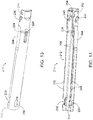
- FIGS. 13-19 show an exemplary lower jaw (210) after at least one manufacturing process is performed to lower jaw blank (110).
- outwardly extending flanges (114, 116) have been removed using at least one manufacturing process (e.g. one or more stamping operations).
- Lower jaw (210) includes a U-shaped body portion (212) that includes a bottom wall (218) interposed between opposing side walls (220, 222). The inside of U-shaped body portion (212) forms a channel configured to receive a staple cartridge. Side walls (220, 222) taper outwardly at outwardly tapering portions (224, 226).
- bottom wall (218) includes a proximal aperture (228) and a distal elongated aperture (230) that extend completely through inner and outer surfaces (232, 234) of bottom wall (218).
- Proximal aperture (228) and distal elongated aperture (230) are connected by a longitudinally extending channel (229).
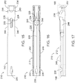
- Side walls (220, 222) include one or more apertures and cutouts. As shown in FIGS. 13-14 and 16-17 , side wall (220) includes a proximal aperture (236) and a distal cutout (238). Similarly, side wall (222) includes a proximal aperture (240) and a distal cutout (242). One or more manufacturing processes (e.g. one or more stamping operations) may be performed to impart proximal apertures (236, 240) and distal cutouts (238, 242) to the intermediate state of the lower jaw, where the intermediate state occurs at a point in time between lower jaw blank (110) and lower jaw (210)). Additionally, as shown, side walls (220, 222) also include inwardly tapering portions (244, 246), recessed portions (248, 250), and apertures (252, 254).
- FIG. 17 shows a left side view of lower jaw (210) including proximal aperture (236) and distal cutout (238), with proximal aperture (240) and distal cutout (242) being mirror images thereof.
- Proximal aperture (236) is described in detail below; however, the principles and accompanying features apply equally to proximal aperture (240).
- FIG. 18A shows a detailed view of proximal aperture (236) after being formed but prior to be machined
- FIG. 18B shows a detailed view of proximal aperture (236) of FIG. 17 after having been machined.
- Proximal aperture (236) is generally kidney shaped. As shown in FIG.
- proximal aperture (236) has a near net shape with an initial area (A1) defined by the continuous solid line.
- near net shape means that the initial forming operations create an intermediate (near net) shape that is very close to the final (net) shape, which reduces the need and associated cost of significant surface finishing.
- These initial forming operations may include, for example, stamping, additive manufacturing, selective laser melting, direct metal laser sintering, and/or metal injection molding.
- proximal aperture (236) has a machined shape with a machined area (A2) defined by the continuous solid line, with the dashed line denoting the near net shape shown in FIG. 18A .
- A2 machined area
- only distal portions of proximal aperture (236) are machined, such that the remainder of proximal aperture (236) is not machined.
- only upper, middle, and lower distal surfaces (256a, 258a, 260a) are machined which results in upper, middle, and lower distal surfaces (256b, 258b, 260b) after the machining operation(s).
- FIG. 18A-18B only upper, middle, and lower distal surfaces (256a, 258a, 260a) are machined which results in upper, middle, and lower distal surfaces (256b, 258b, 260b) after the machining operation(s).
- proximal aperture (236) has a machined area (A2) that is greater than initial area (A1), since material is removed from upper, middle, and lower distal surfaces (256a, 258a, 260a) to form upper, middle, and lower distal surfaces (256b, 258b, 260b).
- A2 initial area
- PI machined perimeter
- P2 machined perimeter
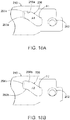
- FIGS. 19A-19B show distal cutout (238). More specifically, FIG. 19A shows a detailed view of distal cutout (238) after being formed but prior to be machined, while FIG. 19B shows a detailed view of distal cutout (238) after being machined. Similar to proximal aperture (236, 240), distal cutout (242) is a mirror image of distal cutout (238). As a result, the principles and accompanying features described for distal cutout (238) apply equally to distal cutout (242). As shown in FIGS. 19A-19B , distal cutout (238) includes a bottom wall (262a), a proximal wall (264a), and a distal wall (266a), forming a generally rectangular shape.
- distal cutout (238) has near net shape with an obtuse interior angle ( ⁇ 1). More specifically, near net shapes produce an obtuse angle between bottom and proximal walls (262a, 264a) and an obtuse angle ( ⁇ 1) between bottom and distal walls (262a, 266a).
- distal cutout (238) has a machined shape with approximately 90-degree interior angles ( ⁇ 2).
- the near net shape of distal cutout (238) with obtuse interior angles ( ⁇ 1) obtained using at least one stamping process are machined into machined shapes with approximately 90-degree interior angles ( ⁇ 2).
- distal cutout (238) is machined to have a 90-degree angle ( ⁇ 2) between bottom and proximal walls (262b, 264b) and 90-degree angle ( ⁇ 2) between bottom and distal walls (262b, 266b).
- top edges (268a, 270a) of FIG. 19A surrounding distal cutout (242) are machined to top edges (268b, 270b) of FIG. 19B .
- the machined shape is the finalized shape, however more manufacturing operations may be performed if desired.
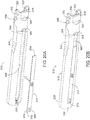
- FIGS. 20A-20B show a second exemplary lower jaw (310).
- Lower jaw (310) comprises a U-shaped body portion (312), a bottom wall (318), opposing side walls (320, 322), a tapering portion (324), a proximal aperture (328), inner and outer surfaces (332, 334) of bottom wall (318), proximal apertures (336, 340), an inwardly tapering portion (344), and an aperture (352).
- Proximal apertures (336, 340) are formed and subsequently machined using a method similar to that described with respect to proximal apertures (236, 240).
- lower jaw (310) does not include distal cutouts, similar to distal cutouts (238, 242) described above with respect to lower jaw (210). However, if desired, distal cutouts may be imparted similar to distal cutouts (238, 242) of lower jaw (210).
- outer surface (334) of bottom wall (318) includes a recessed portion (368) that extends longitudinally. Recessed portion (368) terminates proximally at proximal aperture (328) and distally at a distal wall (370).
- Recessed portion (368) is configured to receive a lower longitudinally extending back member (372) having proximal and distal ends (374, 376). Projections (378, 380) of lower longitudinally extending back member (372) extend distally from distal end (376) of lower longitudinally extending back member (372). Lower longitudinally extending back member (372) is configured to provide additional support for bottom wall (318). Outer surface (382) of lower longitudinally extending back member (372) may extend flush with outer surface (334) of bottom wall (318). Lower longitudinally extending member (372) may be coupled to outer surface (334) of bottom wall (318) before, during, or after machining of the at least one feature (e.g. proximal apertures (336, 340)). For example, lower longitudinally extending back member (372) may be welded to outer surface (334) of bottom wall (318).
- FIG. 21 shows a method (410) of manufacturing lower jaw (210, 310) of end effector (12) of surgical instrument (10) that includes at least three steps (412, 414, 416).
- the method includes providing a lower jaw blank (110) that includes U-shaped body portion (112).
- U-shaped body portion (112) includes bottom wall (118) interposed between opposing side walls (120, 122).
- lower jaw blank (110) may be formed using one or more manufacturing processes (e.g. one or more sequential stamping operations performed by a stamping machine). Instead of or in addition to one or more stamping operations, lower jaw blank (110) may be formed using additive manufacturing, selective laser melting, direct metal laser sintering, and/or metal injection molding.
- the method also includes forming the at least one feature (e.g. proximal apertures (236, 240, 336) and/or distal cutouts (238, 242)) into at least one of side walls (120, 122).
- the feature e.g. proximal apertures (236, 240, 336)
- distal cutouts (238, 242) has a near net shape.
- the feature e.g. proximal apertures (236, 240, 336) and/or distal cutouts (238, 242)
- the method includes subsequently machining the feature (e.g. proximal apertures (236, 240, 336) and/or distal cutouts (238, 242)) to have a machined shape.
- the features may be imparted simultaneously or sequentially.
- a first feature may be formed in the first side wall through a first manufacturing process
- subsequently a second feature may be formed in the second side wall through a second manufacturing process.
- Non-machined portions of lower jaw (210, 310) have a first surface finish
- machined portions of lower jaw (210, 310) have a second surface finish.
- the second surface finish is finer than the first surface finish.
- the second surface finish may be substantially finer than the first surface finish.
- Step (416) may be performed using a variety of machining tools, for example, using a lathe (420), which may be manually operated or automated.
- FIG. 22 shows a method (510) of manufacturing lower jaw (210, 310) of end effector (12) of surgical instrument (10) that includes at least four steps (512, 514, 516, 518).
- the method includes stamping lower jaw blank (110) to include a U-shaped body portion (112).
- U-shaped body portion (112) of lower jaw blank (110) includes bottom wall (118) and opposing side walls (120, 122).
- U-shaped body portion (112) may be formed using one or more manufacturing processes (e.g. one or more sequential stamping operations performed by a stamping machine (520)).
- U-shaped body portion (112) may be formed using additive manufacturing, selective laser melting, direct metal laser sintering, and/or metal injection molding.
- the method also includes stamping proximal aperture (236, 336) of side wall (220, 320).
- Proximal aperture (236, 336) has a near net shape with first area (A1).
- stamping machine (522) may be the same or different from stamping machines (520).
- a variety of other manufacturing processes may be used instead of, or in addition to, stamping.
- the method also includes stamping side wall (222, 322) to include proximal aperture (240, 340).
- Proximal aperture (240, 340) has a near net shape with first area (A1).
- Stamping proximal aperture (240, 340) may happen before, simultaneously with, or after, the stamping of proximal aperture (236, 336).
- a first feature e.g. proximal aperture (236, 336)
- a second feature e.g. proximal aperture (240, 340)
- the first and second manufacturing processes may be the same or different.
- a variety of other manufacturing processes may be used instead of or in addition to stamping of proximal aperture (240, 340).
- the method also includes subsequently machining proximal apertures (236, 240, 336, 340) to have machined shapes with second areas.
- Second area (A2) is less than first area (A1).
- distal portions e.g. distal surfaces (256a, 258a, 260a) of proximal apertures (236, 240, 336, 340
- distal portions e.g. distal surfaces (256b, 258b, 260b)
- the machining of proximal aperture (240) may happen before, simultaneously with, or after the machining of proximal aperture (236).
- Non-machined portions of lower jaw (210, 310) have a first surface finish and machined portions of lower jaw (210, 310) have a second surface finish.
- the second surface finish is finer than the first surface finish.
- the second surface finish may be substantially finer than the first surface finish.
- Step (518) may be performed using a variety of machining tools, for example, using a lathe (526), which may be manually operated or automated.
- a method of manufacturing a lower jaw of an end effector of a surgical instrument comprising: (a) providing a lower jaw that includes a U-shaped body portion, wherein the U-shaped body portion includes a bottom wall interposed between first and second opposing side walls; (b) forming at least one feature into at least one of the first and second side walls, wherein the at least one feature has a near net shape; and (c) subsequently machining the at least one feature to have a machined shape.
- Example 1 wherein forming the at least one feature comprises performing at least one stamping process to form the at least one feature after providing the lower jaw.
- Example 1 wherein forming the at least one feature further comprises forming a first feature in the first side wall through a first manufacturing process, and subsequently forming a second feature in the second side wall through a second manufacturing process.
- the at least one feature comprises a first distal cutout in the first side wall and a second distal cutout in the second side wall, wherein the first and second distal cutouts are configured to align a staple cartridge, wherein the at least one feature comprises a first distal cutout in the first side wall and a second distal cutout in the second side wall.
- the at least one feature comprises a first proximal aperture in the first side wall and a second proximal aperture in the second side wall.
- Example 6 The method of Example 6, wherein only distal portions of the first and second proximal apertures are machined such that the remainder of the first and second proximal apertures are not machined.
- Example 6 The method of Example 6 or Example 7, wherein the near net shapes of the first and second proximal apertures have a first area, wherein the machined shapes of the first and second proximal apertures have a second area that is greater than the first area.
- providing the lower jaw comprises forming the lower jaw to include the U-shaped body portion with first and second outwardly extending flanges, wherein the first outwardly extending flange extends from the first side wall and the second outwardly extending flange extends from the second side wall.
- Example 9 wherein forming the lower jaw comprises a first stamping process to form the U-shaped body portion and the first and second outwardly extending flanges, wherein forming at least one feature includes a second subsequent stamping process to impart the at least one feature.
- Example 9 wherein forming the lower jaw comprises forming the lower jaw using at least one of additive manufacturing, selective laser melting, direct metal laser sintering, or metal injection molding.
- Example 9 The method of Example 9 or Example 10, wherein the method further comprises providing a flat body prior to forming the lower jaw to include a U-shaped body portion.
- the method further comprises coupling a lower longitudinally extending back to a bottom surface of the bottom wall.
- a method of manufacturing a lower jaw of an end effector of a surgical instrument comprising: (a) stamping a lower jaw of an end effector of the surgical instrument to include a U-shaped body portion, wherein the U-shaped body portion includes a bottom wall and opposing first and second side walls; (b) stamping the first wall to includes a first proximal aperture, wherein the first proximal aperture has a near net shape with a first area; (c) stamping the second wall to include a second proximal aperture, wherein the second proximal aperture has a near net shape with the first area; and (d) subsequently machining the first and second proximal apertures to have machined shapes with second areas, wherein the second areas are greater than the first areas.
- Example 16 subsequently machining only distal portions of the first and second proximal apertures such that the remainder of the first and second proximal apertures are not machined.
- An instrument comprising: (a) a body; (b) a shaft extending from the body; and (c) an end effector in communication with the shaft, wherein the end effector is operable to compress, staple, and cut tissue, wherein the end effector includes a lower jaw, wherein the lower jaw comprises: (i) a bottom wall, (ii) a first side wall extending from the bottom wall, wherein the first side wall includes a first feature having a first machined shape produced by machining a first initial near net shape, and (iii) a second side wall extending from the bottom wall and disposed opposite the first side wall, wherein the second side wall includes a second feature having a second machined shape produced by machining a second initial near net shape.
- Example 18 The instrument of Example 18, wherein the first feature includes a first proximal aperture and the second feature includes a second proximal aperture, wherein the first and second proximal apertures have machined shapes with machined areas that are greater than initial areas produced by the first and second initial near net shapes of the first and second proximal apertures.
- Example 18 The instrument of Example 18 or Example 19, wherein the first feature includes a first distal cutout in the first side wall and the second feature includes a second distal cutout in the second side wall, wherein the first and second distal cutouts are configured to align a staple cartridge, wherein the machined shapes of the first and second distal cutouts produce 90-degree interior angles that are initially formed in the first and second initial near net shapes as obtuse interior angles using at least one stamping process.
- first feature includes a first distal cutout in the first side wall
- second feature includes a second distal cutout in the second side wall
- first and second distal cutouts are configured to align a staple cartridge, wherein the first and second initial near net shapes produce obtuse interior angles, wherein the first and second machined shapes produce 90-degree interior angles.
- Example 18 The instrument of any one or more of Example 18 and Examples 20 through 24, wherein the first feature includes a first proximal aperture in the first side wall, wherein the second feature includes a second proximal aperture in the second side wall.
- Example 19 The instrument of Example 19 or Example 25, wherein only distal portions of the first and second proximal apertures are machined such that the remainder of the first and second proximal apertures are not machined.
- Example 28 The instrument of Example 28, wherein the first and second outwardly extending flanges are configured to be removed using at least one manufacturing process.
- Versions of the devices described above may have application in conventional medical treatments and procedures conducted by a medical professional, as well as application in robotic-assisted medical treatments and procedures.
- various teachings herein may be readily incorporated into a robotic surgical system such as the DAVINCITM system by Intuitive Surgical, Inc., of Sunnyvale, California.
- Versions of the devices described above may be designed to be disposed of after a single use, or they can be designed to be used multiple times. Versions may, in either or both cases, be reconditioned for reuse after at least one use. Reconditioning may include any combination of the steps of disassembly of the device, followed by cleaning or replacement of particular pieces, and subsequent reassembly. In particular, some versions of the device may be disassembled, and any number of the particular pieces or parts of the device may be selectively replaced or removed in any combination. Upon cleaning and/or replacement of particular parts, some versions of the device may be reassembled for subsequent use either at a reconditioning facility, or by a user immediately prior to a procedure.
- reconditioning of a device may utilize a variety of techniques for disassembly, cleaning/replacement, and reassembly. Use of such techniques, and the resulting reconditioned device, are all within the scope of the present application.
- versions described herein may be sterilized before and/or after a procedure.
- the device is placed in a closed and sealed container, such as a plastic or TYVEK bag.
- the container and device may then be placed in a field of radiation that can penetrate the container, such as gamma radiation, x-rays, or high-energy electrons.
- the radiation may kill bacteria on the device and in the container.
- the sterilized device may then be stored in the sterile container for later use.
- a device may also be sterilized using any other technique known in the art, including but not limited to beta or gamma radiation, ethylene oxide, or steam.
Landscapes
- Health & Medical Sciences (AREA)
- Engineering & Computer Science (AREA)
- Surgery (AREA)
- Life Sciences & Earth Sciences (AREA)
- Mechanical Engineering (AREA)
- Heart & Thoracic Surgery (AREA)
- Biomedical Technology (AREA)
- Medical Informatics (AREA)
- Molecular Biology (AREA)
- Animal Behavior & Ethology (AREA)
- General Health & Medical Sciences (AREA)
- Public Health (AREA)
- Veterinary Medicine (AREA)
- Nuclear Medicine, Radiotherapy & Molecular Imaging (AREA)
- Surgical Instruments (AREA)
Applications Claiming Priority (1)
| Application Number | Priority Date | Filing Date | Title |
|---|---|---|---|
| US16/236,688 US11134941B2 (en) | 2018-12-31 | 2018-12-31 | Cartridge receiving jaw for surgical stapler and associated method of manufacture with stamping |
Publications (3)
| Publication Number | Publication Date |
|---|---|
| EP3673832A1 true EP3673832A1 (de) | 2020-07-01 |
| EP3673832B1 EP3673832B1 (de) | 2025-06-04 |
| EP3673832C0 EP3673832C0 (de) | 2025-06-04 |
Family
ID=69055866
Family Applications (1)
| Application Number | Title | Priority Date | Filing Date |
|---|---|---|---|
| EP19220072.3A Active EP3673832B1 (de) | 2018-12-31 | 2019-12-30 | Kartuschenaufnahmebacke für chirurgische klammervorrichtung und zugehöriges herstellungsverfahren mit stanzteil |
Country Status (6)
| Country | Link |
|---|---|
| US (2) | US11134941B2 (de) |
| EP (1) | EP3673832B1 (de) |
| JP (1) | JP2022515655A (de) |
| CN (1) | CN113260321B (de) |
| BR (1) | BR112021012567A2 (de) |
| WO (1) | WO2020141402A1 (de) |
Families Citing this family (1)
| Publication number | Priority date | Publication date | Assignee | Title |
|---|---|---|---|---|
| US11134941B2 (en) | 2018-12-31 | 2021-10-05 | Cilag Gmbh International | Cartridge receiving jaw for surgical stapler and associated method of manufacture with stamping |
Citations (14)
| Publication number | Priority date | Publication date | Assignee | Title |
|---|---|---|---|---|
| US20070175961A1 (en) * | 2006-01-31 | 2007-08-02 | Shelton Frederick E Iv | Electro-mechanical surgical cutting and fastening instrument having a rotary firing and closure system with parallel closure and anvil alignment components |
| US7380696B2 (en) | 2003-05-20 | 2008-06-03 | Ethicon Endo-Surgery, Inc. | Articulating surgical stapling instrument incorporating a two-piece E-beam firing mechanism |
| WO2011028196A2 (en) * | 2009-08-24 | 2011-03-10 | Vitalitec International, Inc. | Method of manufacture of clip applying jaws |
| US8408439B2 (en) | 2007-06-22 | 2013-04-02 | Ethicon Endo-Surgery, Inc. | Surgical stapling instrument with an articulatable end effector |
| US8453914B2 (en) | 2009-12-24 | 2013-06-04 | Ethicon Endo-Surgery, Inc. | Motor-driven surgical cutting instrument with electric actuator directional control assembly |
| US20140239037A1 (en) | 2013-02-28 | 2014-08-28 | Ethicon Endo-Surgery, Inc. | Staple forming features for surgical stapling instrument |
| US9186142B2 (en) | 2013-02-28 | 2015-11-17 | Ethicon Endo-Surgery, Inc. | Surgical instrument end effector articulation drive with pinion and opposing racks |
| US9517065B2 (en) | 2013-02-28 | 2016-12-13 | Ethicon Endo-Surgery, Llc | Integrated tissue positioning and jaw alignment features for surgical stapler |
| US9717497B2 (en) | 2013-02-28 | 2017-08-01 | Ethicon Llc | Lockout feature for movable cutting member of surgical instrument |
| US20170290584A1 (en) * | 2016-04-12 | 2017-10-12 | Applied Medical Resources Corporation | Reload shaft assembly for surgical stapler |
| US9795379B2 (en) | 2013-02-28 | 2017-10-24 | Ethicon Llc | Surgical instrument with multi-diameter shaft |
| US9808248B2 (en) | 2013-02-28 | 2017-11-07 | Ethicon Llc | Installation features for surgical instrument end effector cartridge |
| US9839421B2 (en) | 2013-02-28 | 2017-12-12 | Ethicon Llc | Jaw closure feature for end effector of surgical instrument |
| US20180368840A1 (en) * | 2017-06-27 | 2018-12-27 | Ethicon Llc | Surgical anvil arrangements |
Family Cites Families (63)
| Publication number | Priority date | Publication date | Assignee | Title |
|---|---|---|---|---|
| JPS5240252A (en) * | 1975-09-25 | 1977-03-29 | Hitachi Ltd | Proces of a thick plate gear blank |
| JPS5813433A (ja) * | 1981-07-14 | 1983-01-25 | Daido Kogyo Co Ltd | コンベヤチエ−ンにおけるリンクプレ−トの製造方法 |
| US5366459A (en) | 1987-05-14 | 1994-11-22 | Inbae Yoon | Surgical clip and clip application procedures |
| US5333773A (en) | 1991-08-23 | 1994-08-02 | Ethicon, Inc. | Sealing means for endoscopic surgical anastomosis stapling instrument |
| GR920100358A (el) | 1991-08-23 | 1993-06-07 | Ethicon Inc | Οργανο συρραφής χειρουργικής αναστομώσεως. |
| US5350104A (en) | 1991-08-23 | 1994-09-27 | Ethicon, Inc. | Sealing means for endoscopic surgical anastomosis stapling instrument |
| US5163945A (en) | 1991-10-18 | 1992-11-17 | Ethicon, Inc. | Surgical clip applier |
| US5342373A (en) | 1992-09-14 | 1994-08-30 | Ethicon, Inc. | Sterile clips and instrument for their placement |
| US5403312A (en) | 1993-07-22 | 1995-04-04 | Ethicon, Inc. | Electrosurgical hemostatic device |
| US5431668A (en) | 1993-04-29 | 1995-07-11 | Ethicon, Inc. | Ligating clip applier |
| CA2143560C (en) | 1994-03-02 | 2007-01-16 | Mark Fogelberg | Sterile occlusion fasteners and instrument and method for their placement |
| US5951574A (en) | 1998-10-23 | 1999-09-14 | Ethicon Endo-Surgery, Inc. | Multiple clip applier having a split feeding mechanism |
| JP4290850B2 (ja) * | 2000-05-10 | 2009-07-08 | 本田技研工業株式会社 | アルミニウム基複合材製円盤状部品のプレス成形方法 |
| JP2003136152A (ja) * | 2001-11-02 | 2003-05-14 | Mitsubishi Heavy Ind Ltd | アルミ合金製タンク用フランジの製造方法 |
| US7000818B2 (en) | 2003-05-20 | 2006-02-21 | Ethicon, Endo-Surger, Inc. | Surgical stapling instrument having separate distinct closing and firing systems |
| US7204404B2 (en) | 2003-12-30 | 2007-04-17 | Ethicon Endo-Surgery, Inc. | Slotted pins guiding knife in a curved cutter stapler |
| US7147140B2 (en) | 2003-12-30 | 2006-12-12 | Ethicon Endo - Surgery, Inc. | Cartridge retainer for a curved cutter stapler |
| US6988650B2 (en) | 2003-12-30 | 2006-01-24 | Ethicon Endo-Surgery, Inc. | Retaining pin lever advancement mechanism for a curved cutter stapler |
| US7134587B2 (en) | 2003-12-30 | 2006-11-14 | Ethicon Endo-Surgery, Inc. | Knife retraction arm for a curved cutter stapler |
| US20050143759A1 (en) | 2003-12-30 | 2005-06-30 | Kelly William D. | Curved cutter stapler shaped for male pelvis |
| US20050139636A1 (en) | 2003-12-30 | 2005-06-30 | Schwemberger Richard F. | Replaceable cartridge module for a surgical stapling and cutting instrument |
| US7207472B2 (en) | 2003-12-30 | 2007-04-24 | Ethicon Endo-Surgery, Inc. | Cartridge with locking knife for a curved cutter stapler |
| US20050145672A1 (en) | 2003-12-30 | 2005-07-07 | Schwemberger Richard F. | Curved cutter stapler with aligned tissue retention feature |
| US9072535B2 (en) | 2011-05-27 | 2015-07-07 | Ethicon Endo-Surgery, Inc. | Surgical stapling instruments with rotatable staple deployment arrangements |
| JP4358757B2 (ja) * | 2005-01-28 | 2009-11-04 | オリンパス株式会社 | カップ形状部品、カップ形状部品製造方法およびカップ形状部品製造装置 |
| US7686820B2 (en) | 2005-04-14 | 2010-03-30 | Ethicon Endo-Surgery, Inc. | Surgical clip applier ratchet mechanism |
| US7261724B2 (en) | 2005-04-14 | 2007-08-28 | Ethicon Endo-Surgery, Inc. | Surgical clip advancement mechanism |
| US7731724B2 (en) | 2005-04-14 | 2010-06-08 | Ethicon Endo-Surgery, Inc. | Surgical clip advancement and alignment mechanism |
| US8038686B2 (en) | 2005-04-14 | 2011-10-18 | Ethicon Endo-Surgery, Inc. | Clip applier configured to prevent clip fallout |
| US7699860B2 (en) | 2005-04-14 | 2010-04-20 | Ethicon Endo-Surgery, Inc. | Surgical clip |
| US7670334B2 (en) | 2006-01-10 | 2010-03-02 | Ethicon Endo-Surgery, Inc. | Surgical instrument having an articulating end effector |
| US20070175955A1 (en) | 2006-01-31 | 2007-08-02 | Shelton Frederick E Iv | Surgical cutting and fastening instrument with closure trigger locking mechanism |
| US7845537B2 (en) | 2006-01-31 | 2010-12-07 | Ethicon Endo-Surgery, Inc. | Surgical instrument having recording capabilities |
| US7422139B2 (en) | 2006-01-31 | 2008-09-09 | Ethicon Endo-Surgery, Inc. | Motor-driven surgical cutting fastening instrument with tactile position feedback |
| US8322455B2 (en) * | 2006-06-27 | 2012-12-04 | Ethicon Endo-Surgery, Inc. | Manually driven surgical cutting and fastening instrument |
| US7753245B2 (en) | 2007-06-22 | 2010-07-13 | Ethicon Endo-Surgery, Inc. | Surgical stapling instruments |
| JP4958717B2 (ja) * | 2007-10-11 | 2012-06-20 | 株式会社神戸製鋼所 | 車輌用フード及び車輌フード用補強材 |
| US8561870B2 (en) | 2008-02-13 | 2013-10-22 | Ethicon Endo-Surgery, Inc. | Surgical stapling instrument |
| US7980443B2 (en) | 2008-02-15 | 2011-07-19 | Ethicon Endo-Surgery, Inc. | End effectors for a surgical cutting and stapling instrument |
| US20090206142A1 (en) * | 2008-02-15 | 2009-08-20 | Ethicon Endo-Surgery, Inc. | Buttress material for a surgical stapling instrument |
| US8210411B2 (en) | 2008-09-23 | 2012-07-03 | Ethicon Endo-Surgery, Inc. | Motor-driven surgical cutting instrument |
| US8608045B2 (en) | 2008-10-10 | 2013-12-17 | Ethicon Endo-Sugery, Inc. | Powered surgical cutting and stapling apparatus with manually retractable firing system |
| US8517239B2 (en) * | 2009-02-05 | 2013-08-27 | Ethicon Endo-Surgery, Inc. | Surgical stapling instrument comprising a magnetic element driver |
| US8262679B2 (en) | 2009-10-09 | 2012-09-11 | Ethicon Endo-Surgery, Inc. | Clip advancer |
| US8733613B2 (en) | 2010-09-29 | 2014-05-27 | Ethicon Endo-Surgery, Inc. | Staple cartridge |
| US8474677B2 (en) | 2010-09-30 | 2013-07-02 | Ethicon Endo-Surgery, Inc. | Fastener system comprising a retention matrix and a cover |
| US8746532B2 (en) | 2011-05-19 | 2014-06-10 | Ethicon Endo-Surgery, Inc. | Anvil and cartridge alignment configuration for a circular stapler |
| US9101358B2 (en) | 2012-06-15 | 2015-08-11 | Ethicon Endo-Surgery, Inc. | Articulatable surgical instrument comprising a firing drive |
| US9867615B2 (en) | 2013-02-28 | 2018-01-16 | Ethicon Llc | Surgical instrument with articulation lock having a detenting binary spring |
| US9345481B2 (en) | 2013-03-13 | 2016-05-24 | Ethicon Endo-Surgery, Llc | Staple cartridge tissue thickness sensor system |
| US10478189B2 (en) | 2015-06-26 | 2019-11-19 | Ethicon Llc | Method of applying an annular array of staples to tissue |
| US20150083772A1 (en) | 2013-09-23 | 2015-03-26 | Ethicon Endo-Surgery, Inc. | Surgical stapler with rotary cam drive and return |
| US20180132849A1 (en) | 2016-11-14 | 2018-05-17 | Ethicon Endo-Surgery, Llc | Staple forming pocket configurations for circular surgical stapler anvil |
| US10980542B2 (en) | 2016-11-14 | 2021-04-20 | Ethicon Llc | Circular surgical stapler with recessed deck |
| US9713469B2 (en) | 2013-09-23 | 2017-07-25 | Ethicon Llc | Surgical stapler with rotary cam drive |
| US10729444B2 (en) | 2017-04-28 | 2020-08-04 | Ethicon Llc | Liquid-immune trigger circuit for surgical instrument |
| US10709452B2 (en) | 2013-09-23 | 2020-07-14 | Ethicon Llc | Methods and systems for performing circular stapling |
| US10695068B2 (en) | 2017-04-28 | 2020-06-30 | Ethicon Llc | Hysteresis removal feature in surgical stapling instrument |
| US9936949B2 (en) | 2013-09-23 | 2018-04-10 | Ethicon Llc | Surgical stapling instrument with drive assembly having toggle features |
| US9907552B2 (en) | 2013-09-23 | 2018-03-06 | Ethicon Llc | Control features for motorized surgical stapling instrument |
| US10524795B2 (en) | 2015-07-30 | 2020-01-07 | Ethicon Llc | Surgical instrument comprising systems for permitting the optional transection of tissue |
| US11324503B2 (en) * | 2017-06-27 | 2022-05-10 | Cilag Gmbh International | Surgical firing member arrangements |
| US11134941B2 (en) | 2018-12-31 | 2021-10-05 | Cilag Gmbh International | Cartridge receiving jaw for surgical stapler and associated method of manufacture with stamping |
-
2018
- 2018-12-31 US US16/236,688 patent/US11134941B2/en active Active
-
2019
- 2019-12-21 CN CN201980087340.3A patent/CN113260321B/zh active Active
- 2019-12-21 JP JP2021538244A patent/JP2022515655A/ja active Pending
- 2019-12-21 WO PCT/IB2019/061248 patent/WO2020141402A1/en not_active Ceased
- 2019-12-21 BR BR112021012567-1A patent/BR112021012567A2/pt not_active IP Right Cessation
- 2019-12-30 EP EP19220072.3A patent/EP3673832B1/de active Active
-
2021
- 2021-05-27 US US17/331,917 patent/US11744585B2/en active Active
Patent Citations (14)
| Publication number | Priority date | Publication date | Assignee | Title |
|---|---|---|---|---|
| US7380696B2 (en) | 2003-05-20 | 2008-06-03 | Ethicon Endo-Surgery, Inc. | Articulating surgical stapling instrument incorporating a two-piece E-beam firing mechanism |
| US20070175961A1 (en) * | 2006-01-31 | 2007-08-02 | Shelton Frederick E Iv | Electro-mechanical surgical cutting and fastening instrument having a rotary firing and closure system with parallel closure and anvil alignment components |
| US8408439B2 (en) | 2007-06-22 | 2013-04-02 | Ethicon Endo-Surgery, Inc. | Surgical stapling instrument with an articulatable end effector |
| WO2011028196A2 (en) * | 2009-08-24 | 2011-03-10 | Vitalitec International, Inc. | Method of manufacture of clip applying jaws |
| US8453914B2 (en) | 2009-12-24 | 2013-06-04 | Ethicon Endo-Surgery, Inc. | Motor-driven surgical cutting instrument with electric actuator directional control assembly |
| US9186142B2 (en) | 2013-02-28 | 2015-11-17 | Ethicon Endo-Surgery, Inc. | Surgical instrument end effector articulation drive with pinion and opposing racks |
| US20140239037A1 (en) | 2013-02-28 | 2014-08-28 | Ethicon Endo-Surgery, Inc. | Staple forming features for surgical stapling instrument |
| US9517065B2 (en) | 2013-02-28 | 2016-12-13 | Ethicon Endo-Surgery, Llc | Integrated tissue positioning and jaw alignment features for surgical stapler |
| US9717497B2 (en) | 2013-02-28 | 2017-08-01 | Ethicon Llc | Lockout feature for movable cutting member of surgical instrument |
| US9795379B2 (en) | 2013-02-28 | 2017-10-24 | Ethicon Llc | Surgical instrument with multi-diameter shaft |
| US9808248B2 (en) | 2013-02-28 | 2017-11-07 | Ethicon Llc | Installation features for surgical instrument end effector cartridge |
| US9839421B2 (en) | 2013-02-28 | 2017-12-12 | Ethicon Llc | Jaw closure feature for end effector of surgical instrument |
| US20170290584A1 (en) * | 2016-04-12 | 2017-10-12 | Applied Medical Resources Corporation | Reload shaft assembly for surgical stapler |
| US20180368840A1 (en) * | 2017-06-27 | 2018-12-27 | Ethicon Llc | Surgical anvil arrangements |
Non-Patent Citations (2)
| Title |
|---|
| DANIELE MARINI ET AL: "Near net shape manufacturing of metal: A review of approaches and their evolutions", INSTITUTION OF MECHANICAL ENGINEERS. PROCEEDINGS. JOURNAL OF ENGINEERING MANUFACTURE., vol. 232, no. 4, 16 March 2018 (2018-03-16), GB, pages 650 - 669, XP055677584, ISSN: 0954-4054, DOI: 10.1177/0954405417708220 * |
| TIM KARDISH: "Where Component Design Functionality And Cost Reduction Converge: Cold Formed Medical Devices Vs. Traditional Manufacturing Techniques", MEDICAL DESIGN BRIEF, 7 May 2014 (2014-05-07), XP055677598, Retrieved from the Internet <URL:https://www.sussexwire.com/docs/SussexWire-MDB-article-20140507.pdf> [retrieved on 20200318] * |
Also Published As
| Publication number | Publication date |
|---|---|
| US11744585B2 (en) | 2023-09-05 |
| US11134941B2 (en) | 2021-10-05 |
| US20210346019A1 (en) | 2021-11-11 |
| US20200205813A1 (en) | 2020-07-02 |
| BR112021012567A2 (pt) | 2021-09-14 |
| EP3673832B1 (de) | 2025-06-04 |
| WO2020141402A1 (en) | 2020-07-09 |
| JP2022515655A (ja) | 2022-02-21 |
| CN113260321B (zh) | 2024-11-08 |
| CN113260321A (zh) | 2021-08-13 |
| EP3673832C0 (de) | 2025-06-04 |
Similar Documents
| Publication | Publication Date | Title |
|---|---|---|
| US11051809B2 (en) | Cartridge receiving jaw for surgical stapler and associated method of manufacture with MIM | |
| US12133649B2 (en) | Surgical stapler cartridge retainer with ejector feature | |
| US11045193B2 (en) | Anvil assembly for linear surgical stapler | |
| US11540826B2 (en) | Surgical stapler end effector sled having cartridge wall support feature | |
| US12295572B2 (en) | Knife for surgical stapler and associated method of manufacture with MIM and HIP | |
| EP3597122A1 (de) | Endeffektorkomponente für chirurgisches klammergerät mit gelenk und asymmetrischer verformbarer spitze | |
| US11832814B2 (en) | Surgical stapler end effector sled having tapered distal end | |
| US12089843B2 (en) | Surgical stapler end effector sled having staple driver support feature | |
| EP3673833A2 (de) | Rahmen für chirurgisches klammergerät und zugehöriges verfahren zur herstellung mit prägung | |
| US11553912B2 (en) | Surgical stapler end effector sled having multiple surface finishes | |
| US12064112B2 (en) | Surgical stapler end effector sled having cartridge biasing feature | |
| US11744585B2 (en) | Cartridge receiving jaw for surgical stapler and associated method of manufacture with stamping | |
| US11607217B2 (en) | Surgical stapler shaft formed of segments of different materials | |
| US12558094B2 (en) | Sled retention and alignment features for surgical stapler |
Legal Events
| Date | Code | Title | Description |
|---|---|---|---|
| PUAI | Public reference made under article 153(3) epc to a published international application that has entered the european phase |
Free format text: ORIGINAL CODE: 0009012 |
|
| STAA | Information on the status of an ep patent application or granted ep patent |
Free format text: STATUS: THE APPLICATION HAS BEEN PUBLISHED |
|
| AK | Designated contracting states |
Kind code of ref document: A1 Designated state(s): AL AT BE BG CH CY CZ DE DK EE ES FI FR GB GR HR HU IE IS IT LI LT LU LV MC MK MT NL NO PL PT RO RS SE SI SK SM TR |
|
| AX | Request for extension of the european patent |
Extension state: BA ME |
|
| STAA | Information on the status of an ep patent application or granted ep patent |
Free format text: STATUS: REQUEST FOR EXAMINATION WAS MADE |
|
| 17P | Request for examination filed |
Effective date: 20210111 |
|
| RBV | Designated contracting states (corrected) |
Designated state(s): AL AT BE BG CH CY CZ DE DK EE ES FI FR GB GR HR HU IE IS IT LI LT LU LV MC MK MT NL NO PL PT RO RS SE SI SK SM TR |
|
| STAA | Information on the status of an ep patent application or granted ep patent |
Free format text: STATUS: EXAMINATION IS IN PROGRESS |
|
| 17Q | First examination report despatched |
Effective date: 20230707 |
|
| GRAP | Despatch of communication of intention to grant a patent |
Free format text: ORIGINAL CODE: EPIDOSNIGR1 |
|
| STAA | Information on the status of an ep patent application or granted ep patent |
Free format text: STATUS: GRANT OF PATENT IS INTENDED |
|
| RIC1 | Information provided on ipc code assigned before grant |
Ipc: A61B 17/29 20060101ALN20241002BHEP Ipc: A61B 17/00 20060101ALN20241002BHEP Ipc: B21D 53/00 20060101ALI20241002BHEP Ipc: B21D 22/02 20060101ALI20241002BHEP Ipc: A61B 17/072 20060101AFI20241002BHEP |
|
| INTG | Intention to grant announced |
Effective date: 20241018 |
|
| GRAJ | Information related to disapproval of communication of intention to grant by the applicant or resumption of examination proceedings by the epo deleted |
Free format text: ORIGINAL CODE: EPIDOSDIGR1 |
|
| STAA | Information on the status of an ep patent application or granted ep patent |
Free format text: STATUS: EXAMINATION IS IN PROGRESS |
|
| GRAP | Despatch of communication of intention to grant a patent |
Free format text: ORIGINAL CODE: EPIDOSNIGR1 |
|
| STAA | Information on the status of an ep patent application or granted ep patent |
Free format text: STATUS: GRANT OF PATENT IS INTENDED |
|
| INTC | Intention to grant announced (deleted) | ||
| RIC1 | Information provided on ipc code assigned before grant |
Ipc: A61B 17/29 20060101ALN20250113BHEP Ipc: A61B 17/00 20060101ALN20250113BHEP Ipc: B21D 53/00 20060101ALI20250113BHEP Ipc: B21D 22/02 20060101ALI20250113BHEP Ipc: A61B 17/072 20060101AFI20250113BHEP |
|
| INTG | Intention to grant announced |
Effective date: 20250129 |
|
| GRAS | Grant fee paid |
Free format text: ORIGINAL CODE: EPIDOSNIGR3 |
|
| GRAA | (expected) grant |
Free format text: ORIGINAL CODE: 0009210 |
|
| STAA | Information on the status of an ep patent application or granted ep patent |
Free format text: STATUS: THE PATENT HAS BEEN GRANTED |
|
| AK | Designated contracting states |
Kind code of ref document: B1 Designated state(s): AL AT BE BG CH CY CZ DE DK EE ES FI FR GB GR HR HU IE IS IT LI LT LU LV MC MK MT NL NO PL PT RO RS SE SI SK SM TR |
|
| REG | Reference to a national code |
Ref country code: GB Ref legal event code: FG4D |
|
| REG | Reference to a national code |
Ref country code: CH Ref legal event code: EP |
|
| REG | Reference to a national code |
Ref country code: DE Ref legal event code: R096 Ref document number: 602019070709 Country of ref document: DE |
|
| REG | Reference to a national code |
Ref country code: IE Ref legal event code: FG4D |
|
| U01 | Request for unitary effect filed |
Effective date: 20250619 |
|
| U07 | Unitary effect registered |
Designated state(s): AT BE BG DE DK EE FI FR IT LT LU LV MT NL PT RO SE SI Effective date: 20250630 |
|
| PG25 | Lapsed in a contracting state [announced via postgrant information from national office to epo] |
Ref country code: ES Free format text: LAPSE BECAUSE OF FAILURE TO SUBMIT A TRANSLATION OF THE DESCRIPTION OR TO PAY THE FEE WITHIN THE PRESCRIBED TIME-LIMIT Effective date: 20250604 |
|
| PG25 | Lapsed in a contracting state [announced via postgrant information from national office to epo] |
Ref country code: GR Free format text: LAPSE BECAUSE OF FAILURE TO SUBMIT A TRANSLATION OF THE DESCRIPTION OR TO PAY THE FEE WITHIN THE PRESCRIBED TIME-LIMIT Effective date: 20250905 Ref country code: NO Free format text: LAPSE BECAUSE OF FAILURE TO SUBMIT A TRANSLATION OF THE DESCRIPTION OR TO PAY THE FEE WITHIN THE PRESCRIBED TIME-LIMIT Effective date: 20250904 |
|
| PG25 | Lapsed in a contracting state [announced via postgrant information from national office to epo] |
Ref country code: PL Free format text: LAPSE BECAUSE OF FAILURE TO SUBMIT A TRANSLATION OF THE DESCRIPTION OR TO PAY THE FEE WITHIN THE PRESCRIBED TIME-LIMIT Effective date: 20250604 |
|
| PG25 | Lapsed in a contracting state [announced via postgrant information from national office to epo] |
Ref country code: HR Free format text: LAPSE BECAUSE OF FAILURE TO SUBMIT A TRANSLATION OF THE DESCRIPTION OR TO PAY THE FEE WITHIN THE PRESCRIBED TIME-LIMIT Effective date: 20250604 |
|
| PG25 | Lapsed in a contracting state [announced via postgrant information from national office to epo] |
Ref country code: RS Free format text: LAPSE BECAUSE OF FAILURE TO SUBMIT A TRANSLATION OF THE DESCRIPTION OR TO PAY THE FEE WITHIN THE PRESCRIBED TIME-LIMIT Effective date: 20250904 |
|
| U20 | Renewal fee for the european patent with unitary effect paid |
Year of fee payment: 7 Effective date: 20251110 |
|
| PG25 | Lapsed in a contracting state [announced via postgrant information from national office to epo] |
Ref country code: IS Free format text: LAPSE BECAUSE OF FAILURE TO SUBMIT A TRANSLATION OF THE DESCRIPTION OR TO PAY THE FEE WITHIN THE PRESCRIBED TIME-LIMIT Effective date: 20251004 |
|
| PGFP | Annual fee paid to national office [announced via postgrant information from national office to epo] |
Ref country code: GB Payment date: 20251114 Year of fee payment: 7 |
|
| PG25 | Lapsed in a contracting state [announced via postgrant information from national office to epo] |
Ref country code: SM Free format text: LAPSE BECAUSE OF FAILURE TO SUBMIT A TRANSLATION OF THE DESCRIPTION OR TO PAY THE FEE WITHIN THE PRESCRIBED TIME-LIMIT Effective date: 20250604 |
|
| PG25 | Lapsed in a contracting state [announced via postgrant information from national office to epo] |
Ref country code: CZ Free format text: LAPSE BECAUSE OF FAILURE TO SUBMIT A TRANSLATION OF THE DESCRIPTION OR TO PAY THE FEE WITHIN THE PRESCRIBED TIME-LIMIT Effective date: 20250604 |
|
| PG25 | Lapsed in a contracting state [announced via postgrant information from national office to epo] |
Ref country code: SK Free format text: LAPSE BECAUSE OF FAILURE TO SUBMIT A TRANSLATION OF THE DESCRIPTION OR TO PAY THE FEE WITHIN THE PRESCRIBED TIME-LIMIT Effective date: 20250604 |
|
| PLBE | No opposition filed within time limit |
Free format text: ORIGINAL CODE: 0009261 |
|
| STAA | Information on the status of an ep patent application or granted ep patent |
Free format text: STATUS: NO OPPOSITION FILED WITHIN TIME LIMIT |
|
| REG | Reference to a national code |
Ref country code: CH Ref legal event code: L10 Free format text: ST27 STATUS EVENT CODE: U-0-0-L10-L00 (AS PROVIDED BY THE NATIONAL OFFICE) Effective date: 20260416 |