EP3673862A1 - Superposition de modèle dentaire à l'aide d'indications cliniques - Google Patents
Superposition de modèle dentaire à l'aide d'indications cliniques Download PDFInfo
- Publication number
- EP3673862A1 EP3673862A1 EP18306867.5A EP18306867A EP3673862A1 EP 3673862 A1 EP3673862 A1 EP 3673862A1 EP 18306867 A EP18306867 A EP 18306867A EP 3673862 A1 EP3673862 A1 EP 3673862A1
- Authority
- EP
- European Patent Office
- Prior art keywords
- model
- tooth
- selected tooth
- dentition
- patient
- Prior art date
- Legal status (The legal status is an assumption and is not a legal conclusion. Google has not performed a legal analysis and makes no representation as to the accuracy of the status listed.)
- Withdrawn
Links
Images


Classifications
-
- G—PHYSICS
- G06—COMPUTING OR CALCULATING; COUNTING
- G06T—IMAGE DATA PROCESSING OR GENERATION, IN GENERAL
- G06T19/00—Manipulating three-dimensional [3D] models or images for computer graphics
- G06T19/20—Editing of three-dimensional [3D] images, e.g. changing shapes or colours, aligning objects or positioning parts
-
- A—HUMAN NECESSITIES
- A61—MEDICAL OR VETERINARY SCIENCE; HYGIENE
- A61C—DENTISTRY; APPARATUS OR METHODS FOR ORAL OR DENTAL HYGIENE
- A61C7/00—Orthodontics, i.e. obtaining or maintaining the desired position of teeth, e.g. by straightening, evening, regulating, separating, or by correcting malocclusions
- A61C7/002—Orthodontic computer assisted systems
-
- A—HUMAN NECESSITIES
- A61—MEDICAL OR VETERINARY SCIENCE; HYGIENE
- A61C—DENTISTRY; APPARATUS OR METHODS FOR ORAL OR DENTAL HYGIENE
- A61C9/00—Impression cups, i.e. impression trays; Impression methods
- A61C9/004—Means or methods for taking digitized impressions
-
- G—PHYSICS
- G06—COMPUTING OR CALCULATING; COUNTING
- G06T—IMAGE DATA PROCESSING OR GENERATION, IN GENERAL
- G06T17/00—Three-dimensional [3D] modelling for computer graphics
- G06T17/20—Finite element generation, e.g. wire-frame surface description, tesselation
-
- G—PHYSICS
- G06—COMPUTING OR CALCULATING; COUNTING
- G06T—IMAGE DATA PROCESSING OR GENERATION, IN GENERAL
- G06T7/00—Image analysis
- G06T7/0002—Inspection of images, e.g. flaw detection
- G06T7/0012—Biomedical image inspection
-
- G—PHYSICS
- G06—COMPUTING OR CALCULATING; COUNTING
- G06T—IMAGE DATA PROCESSING OR GENERATION, IN GENERAL
- G06T7/00—Image analysis
- G06T7/10—Segmentation; Edge detection
-
- G—PHYSICS
- G06—COMPUTING OR CALCULATING; COUNTING
- G06T—IMAGE DATA PROCESSING OR GENERATION, IN GENERAL
- G06T7/00—Image analysis
- G06T7/30—Determination of transform parameters for the alignment of images, i.e. image registration
-
- A—HUMAN NECESSITIES
- A61—MEDICAL OR VETERINARY SCIENCE; HYGIENE
- A61C—DENTISTRY; APPARATUS OR METHODS FOR ORAL OR DENTAL HYGIENE
- A61C7/00—Orthodontics, i.e. obtaining or maintaining the desired position of teeth, e.g. by straightening, evening, regulating, separating, or by correcting malocclusions
- A61C7/002—Orthodontic computer assisted systems
- A61C2007/004—Automatic construction of a set of axes for a tooth or a plurality of teeth
-
- G—PHYSICS
- G06—COMPUTING OR CALCULATING; COUNTING
- G06T—IMAGE DATA PROCESSING OR GENERATION, IN GENERAL
- G06T2207/00—Indexing scheme for image analysis or image enhancement
- G06T2207/10—Image acquisition modality
- G06T2207/10072—Tomographic images
- G06T2207/10081—Computed x-ray tomography [CT]
-
- G—PHYSICS
- G06—COMPUTING OR CALCULATING; COUNTING
- G06T—IMAGE DATA PROCESSING OR GENERATION, IN GENERAL
- G06T2207/00—Indexing scheme for image analysis or image enhancement
- G06T2207/30—Subject of image; Context of image processing
- G06T2207/30004—Biomedical image processing
- G06T2207/30036—Dental; Teeth
-
- G—PHYSICS
- G06—COMPUTING OR CALCULATING; COUNTING
- G06T—IMAGE DATA PROCESSING OR GENERATION, IN GENERAL
- G06T2219/00—Indexing scheme for manipulating 3D models or images for computer graphics
- G06T2219/20—Indexing scheme for editing of 3D models
- G06T2219/2016—Rotation, translation, scaling
Definitions
- the disclosure relates generally to dental imaging and more particularly relates to methods and apparatus for visual comparison of models for assessment of orthodontic treatment.
- Optical intraoral scans produce contours of dentition objects and have been helpful in improving visualization of teeth, gums, and other intra-oral structures.
- Surface contour information can be particularly useful for assessment of tooth condition and has recognized value for supporting various types of dental procedures, such as for restorative dentistry. This can provide a valuable tool to assist the dental practitioner in identifying various problems and in validating other measurements and observations related to the patient's teeth and supporting structures.
- Surface contour information can also be used to generate 3D models of dentition components such as individual teeth; the position and orientation information related to individual teeth can then be used in assessing orthodontic treatment progress.
- an initial model of patient dentition is generated, showing the patient's condition at the beginning of a treatment sequence. Then, periodically, one or more subsequent models may be useful at various stages of the treatment sequence, helping the practitioner to track patient progress over time and to help ascertain what is needed for further tooth adjustment at stages of the treatment process.
- the generated models can be stored and presented as displayed images, allowing the practitioner to view key structures and obtain measurements between features as well as angular measurements.
- An object of the present disclosure is to address the need for improved visualization of treatment progress when using 3D models in restorative and orthodontic dentistry.
- Embodiments of the present disclosure help to automate and simplify comparison of models generated at different stages of patient treatment.
- a method for displaying a superimposition of a second dental model on a first dental model of a patient's dentition executed at least in part on a computer and comprising:
- the term "energizable” relates to a device or set of components that perform an indicated function upon receiving power and, optionally, upon receiving an enabling signal.
- viewer In the context of the present disclosure, the terms “viewer”, “operator”, and “user” are considered to be equivalent and refer to the viewing practitioner, technician, or other person who views and manipulates an image, such as a dental image, on a display monitor.
- An "operator instruction” or “viewer instruction” is obtained from explicit commands entered by the viewer, such as by clicking a button on a camera or by using a computer mouse or by touch screen or keyboard entry.
- the phrase "in signal communication” indicates that two or more devices and/or components are capable of communicating with each other via signals that travel over some type of signal path.
- Signal communication may be wired or wireless.
- the signals may be communication, power, data, or energy signals.
- the signal paths may include physical, electrical, magnetic, electromagnetic, optical, wired, and/or wireless connections between the first device and/or component and second device and/or component.
- the signal paths may also include additional devices and/or components between the first device and/or component and second device and/or component.
- the term "detector” refers to the element that is placed in the patient's mouth, receives radiation, and provides the image content. Such a detector is a digital detector that provides the x-ray image data directly to an imaging system.
- Mesh representation can be provided using either 3D volume radiographic methods such as CBCT or structured light imaging methods using an intraoral camera or scanner, or by using some combination of radiographic and reflection imaging.
- 3D volume radiographic methods such as CBCT or structured light imaging methods using an intraoral camera or scanner, or by using some combination of radiographic and reflection imaging.
- 3D model may be used synonymously in the context of the present disclosure for image structures that visually represent the 3D surface contour of imaged teeth.
- a dense point cloud is formed using techniques familiar to those skilled in the volume imaging arts for surface contour representation and relates generally to methods that identify points in space corresponding to surface features.
- a dense point cloud can be generated, for example, using the reconstructed contour data from one or more reflectance images.
- a mesh can be generated using the same acquired surface contour to identify vertices that serve as the basis for a polygon model for tooth and gum surfaces.
- the mesh and point cloud representations for a 3D surface can have the same visual appearance depending on magnification; computed coordinates for vertices of the mesh and particular points in the point cloud, however, need not be identical.
- the CBCT apparatus can be used for acquiring 3D volume content usable for generating a model image of patient dentition.
- the CBCT apparatus rotates an x-ray source and a detector about the subject and acquires a set having a series of radiographic 2D projection images at different angles about the subject. Reconstruction processes are then used to form a reconstructed 3D volume image of the subject or the object using the set of 2D projection images.
- the CBCT apparatus is typically employed to scan a mold or impression of patient dentition.
- a computer or other type of dedicated logic processor can act as control logic processor for obtaining, processing, and storing image data as part of the CBCT system, along with one or more displays for viewing image results.
- the acquired 3D volume from the CBCT system can be used for generating a model of patient dentition, which may be in the form of a mesh or point cloud, as described subsequently in more detail.
- FIG. 1 shows a surface contour imaging apparatus 90 that can be used for obtaining 3D content for model generation from a succession of reflectance images according to an embodiment of the present disclosure.
- a scanner or camera 16 typically a hand-held digital camera, a color depth camera, handheld 3D scanner, or intra-oral 3D scanner, is scanned through the mouth of patient 12 for acquiring a set having multiple reflectance images and associated depth information.
- a control logic processor 80 configurable to execute programmed instructions, is in signal communication with camera 16 and a display 84. Processor 80 obtains image data from camera 16 and processes this image data along with depth information in order to generate individual 3D views 92. Control logic processor 80 then combines the scanned 3D views in order to generate, store, and optionally render, on display 84, a composite 3D model surface 94.
- the processor can be configured to executed programmed instructions for a sequence, defined in more detail subsequently, of:
- FIG. 2 is a schematic diagram showing an imaging apparatus 70 that can operate as a video camera 24 for polychromatic reflectance image data capture as well as a scanner 28 for executing related projecting and imaging functions used to characterize surface contour with structured light patterns 46.
- a handheld imaging apparatus 70 uses a video camera 24 for image acquisition for both contour scanning and image capture functions according to an embodiment of the present disclosure.
- Control logic processor 80 or other type of computer that may be part of camera 24, controls the operation of an illumination array 10 that generates the structured light and directs the light toward a surface position and controls operation of an imaging sensor array 30.
- Image data from surface 20, such as from a tooth 22, is obtained from imaging sensor array 30 and stored as video image data in a memory 72.
- Imaging sensor array 30 is part of a sensing apparatus 40 that includes an objective lens 34 and associated elements for acquiring video image content.
- Control logic processor 80 in signal communication with camera 24 components that acquire the image, processes the received image data and stores the mapping in memory 72.
- the resulting image from memory 72 is then optionally rendered and displayed on a display 74, which may be part of another computer 75 used for some portion of the processing described herein.
- Memory 72 may also include a display buffer.
- One or more sensors 42 such as a motion sensor, can also be provided as part of scanner 28 circuitry.
- a pattern of lines or other shapes is projected from illumination array 10 toward the surface of an object from a given angle.
- the projected pattern from the illuminated surface position is then viewed from another angle as a contour image, taking advantage of triangulation in order to analyze surface information based on the appearance of contour lines.
- Phase shifting in which the projected pattern is incrementally shifted spatially for obtaining additional measurements at the new locations, is typically applied as part of structured light imaging, used in order to complete the contour mapping of the surface and to increase overall resolution in the contour image.
- use of structured light patterns for surface contour characterization is described in commonly assigned U.S. Patent Application Publications No. US2013/0120532 and No. US2013/0120533 , both entitled “3D INTRAORAL MEASUREMENTS USING OPTICAL MULTILINE METHOD” and incorporated herein in their entirety.
- FIG. 3 shows, with the example of a single line of light L, how patterned light is used for obtaining surface contour information by a scanner using a handheld camera or other portable imaging device.
- a mapping is obtained as an illumination array 10 directs a pattern of light onto a surface 20 and a corresponding image of a line L' is formed on an imaging sensor array 30.
- Each pixel 32 on imaging sensor array 30 maps to a corresponding pixel 12 on illumination array 10 according to modulation by surface 20. Shifts in pixel position, as represented in FIG. 3 , yield useful information about the contour of surface 20. It can be appreciated that the basic pattern shown in FIG.
- Illumination array 10 can utilize any of a number of types of arrays used for light modulation, such as a liquid crystal array or digital micromirror array, such as that provided using the Digital Light Processor or DLP device from Texas Instruments, Dallas, TX. This type of spatial light modulator is used in the illumination path to change the light pattern as needed for the mapping sequence.
- the image of the contour line on the camera simultaneously locates a number of surface points of the imaged object. This speeds the process of gathering many sample points, while the plane of light (and usually also the receiving camera) is laterally moved in order to "paint" some or all of the exterior surface of the object with the plane of light.
- a synchronous succession of multiple structured light patterns can be projected and analyzed together for a number of reasons, including to increase the density of lines for additional reconstructed points and to detect and/or correct incompatible line sequences.
- Use of multiple structured light patterns is described in commonly assigned U.S. Patent Application Publications No. US2013/0120532 and No. US2013/0120533 , both entitled “3D INTRAORAL MEASUREMENTS USING OPTICAL MULTILINE METHOD” and incorporated herein in their entirety.
- FIG. 4 shows surface imaging using a pattern with multiple lines of light. Incremental shifting of the line pattern and other techniques help to compensate for inaccuracies and confusion that can result from abrupt transitions along the surface, whereby it can be difficult to positively identify the segments that correspond to each projected line. In FIG. 4 , for example, it can be difficult over portions of the surface to determine whether line segment 26 is from the same line of illumination as line segment 18 or adjacent line segment 19.
- a computer and software can use triangulation methods to compute the coordinates of numerous illuminated surface points relative to a plane. As the plane is moved to intersect eventually with some or all of the surface of the object, the coordinates of an increasing number of points are accumulated. As a result of this image acquisition, a point cloud of vertex points or vertices can be identified and used to represent the extent of a surface within a volume. The points in the point cloud then represent actual, measured points on the three-dimensional surface of an object.
- a mesh can then be constructed, connecting points on the point cloud as vertices that define individual congruent polygonal faces (typically triangular faces) that characterize the surface shape.
- the full 3D surface contour image model can then be formed by combining the surface contour information provided by the mesh with polychromatic image content obtained from a camera, such as camera 24 that is housed with camera 24 in the embodiment described with reference to FIG. 2 .
- Polychromatic image content can be provided in a number of ways, including the use of a single monochrome imaging sensor with a succession of images obtained using illumination of different primary colors, one color at a time, for example. Alternately, a color imaging sensor could be used.
- Image processing at control logic processor 80 then generates, from the individual line scan data, a contour surface model.
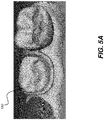
- FIGs. 5A and 5B show a point cloud or mesh 150 generated from a succession of structured light images. Further processing of the point cloud content can be used to generate a mesh as an alternative contour surface model.
- Reflectance imaging can be used for obtaining intraoral surface contour data.
- Surface contour information can alternately be obtained using time-of-flight imaging or range imaging methods, such as structure-from-motion processing, for example.
- Embodiments of the present disclosure address the need for comparing two models by providing a visualization that shows the two models in superimposed form.
- Superimposed display allows the practitioner to quickly and accurately assess and measure progress in adjusting the position of one or more teeth following a treatment period.
- embodiments of the present disclosure use clinical indications to determine which teeth are affected and apply registration techniques that allow visibility of tooth position shift from a suitable reference position.
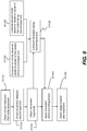
- the logic flow diagram of FIG. 6 shows a global workflow for model superposition using clinical indications for a patient.
- a first model and second model are generated and obtained in model acquisition steps S810, S812, respectively, using apparatus and utilities described previously and known to those skilled in the model generation arts.
- the second model may be acquired following an orthodontic treatment.
- Each model is then similarly segmented and labeled in respective segmentation steps S820, S822.
- Steps S820 and S822 obtain segmentation, labeling, and axis orientation for teeth in the respective model.
- Step S830 identifies, from the clinical indications, "selected" teeth as one or more teeth undergoing treatment that provides incremental movement from initial positions on the first model to target positions on the second model.
- a position determination step S834 obtains the post-treatment target position of each identified selected tooth from the first model and calculates a movement indication that identifies the incremental adjustment in position for the selected tooth, with relation to both translation movement and angle, that is planned between first and second models.
- Direction and magnitude for movement can be specified.
- a selected tooth registration step S840 computes the registration of the one or more selected teeth. Registration can use a feature matching algorithm or can use iterative closest point (ICP) techniques, for example.
- a model registration step S850 computes the registration of the second model onto the first model.
- a display step S860 then renders a view of the registered first and second models, superimposed for practitioner viewing. It can be appreciated that the use of multiple selected teeth is advantageous. Designating a plurality of the segmented teeth as selected teeth provides multiple data points for spatial positioning and thus allows improved accuracy for superimposition of the second 3D model onto the first 3D model and comparison of the two models.
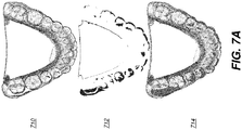
- FIGs. 7A , 7B , and C show examples of the model registration process for superposition with controlled displacement of molars for different cases.
- a first model 710 shows the initial or pre-treatment position of teeth in the mandibular jaw.
- a second model is obtained following a later stage of treatment.
- a difference image 712 shows the amount and general direction of displacement effected from the pre-treatment model at this treatment stage.
- the first molars can be seen to have the same position before and after the treatment stage; there is little or no perceptible transverse movement of first molars.
- a combined model 714 shows the pre-treatment model and post-treatment model superimposed for comparison.
- FIG. 7B shows contraction of distance between the first molars effected during the treatment phase.
- a first model 720 shows the initial or pre-treatment position of teeth in the mandibular jaw.
- a second model is obtained following a later stage of treatment.
- a difference image 722 shows the amount and general direction of displacement effected from the pre-treatment model at this treatment stage.
- a combined model 724 shows the pre-treatment model and post-treatment model superimposed.
- the distance between the two first molars is larger before treatment than after this phase.
- FIG. 7C shows expansion of distance between the first molars effected during the treatment phase.
- a first model 730 shows the initial or pre-treatment position of teeth in the mandibular jaw.
- a second model is obtained following a later stage of treatment.
- a difference image 732 shows the amount and general direction of displacement effected from the pre-treatment model at this treatment stage.
- a combined model 734 shows the pre-treatment model and post-treatment model superimposed, allowing a tooth-by-tooth comparison, for example.
- the distance between the two first molars is larger after treatment than before.
- the difference image such as shown in the examples of FIGs. 7A-7C can be generated to serve as a guide or reference to overall movement of the patient dentition as a result of an orthodontic treatment sequence. Where it is useful, the difference image can be displayed, stored, or transmitted.
- the logic flow diagram of FIG. 8 shows a detailed workflow sequence for model superposition using a clinical indication.
- This sequence can be applied, for example, to selected teeth in position determination step S834 of FIG. 6 .
- it can be determined whether or not the treatment affects tooth position, that is, whether the tooth is fixed or moved as part of the treatment.
- a fixed target determination step S1010 indicates that the targeted position in the first model is the current position of the tooth in the second model. Otherwise, for a tooth that is moved, movement steps S1020 and S1022 determine the direction and magnitude of movement, respectively.
- a position determination step S1030 determines the position of each tooth of the first model following treatment, applying direction and amplitude data from steps S1020 and S1022 for teeth that are to be moved. Step S1030 thus defines the target for tooth position, as the tooth appears in the second model.
- the logic sequence of FIG. 9 shows steps for determining the intended position of a tooth after a treatment interval, using the example of first molar expansion along the buccolingual axis.
- an obtain clinical indications step S1110 the clinical indications for the patient are acquired.
- Clinical indications provide information needed for an obtain movement direction step S1112 and obtain movement magnitude step S1114, similar to steps S1020 and S1022 of FIG. 8 , respectively.
- distance computation steps S1120, S1122 determine the center-to-center distance of first molars along the buccolingual axis for first and second models, respectively.
- a translation computation step S1130 then computes the needed translation for the first molar along the buccolingual axis.
- a translation step S1140 applies the computed translation to the model image content with respect to the intended buccolingual axis.
- An obtain target position step S1150 then computes and reports the target position for the molar following treatment, such as by displaying the target position relative to the model or by providing coordinates or movement vector data.
- FIG. 10A shows a first model and indicates pairs of center points of molars for the contraction, with a pair of target points P' R1 and P' L1 and a pair of actual center points P R1 and P L1 for the first model.
- FIG. 10B shows actual center points P R2 and P L2 for the second model.
- the system display 84 can show either or both models, along with target and actual center points, for example.
- the clinical indications for tooth treatment can provide various types of data including information on one or more fixed teeth such as molars, or on implants.
- Clinical indications can include information on molar expansion or contraction and on sagittal displacement for molars.
- the clinical indications can also include information on torque to be applied on the incisors.
- Clinical indications can also specify mesialization or distalization, as practiced in the orthodontic arts.
- first molars expansion it can be assumed that the molar movement is transversal only, allowing the expansion or contraction computation along an appropriate axis. Expansion or contraction can be measured center-to-center between right and left molars in position for the first model and the intended registered position for the second model. Using this information, it is possible to compute the theoretical positions finally achieved by the molars on the first model.
- a landmark transform familiar to those skilled in linear transforms, can be applied between the theoretical position and the position of the molars on the second model.
- the display of tooth model imposition can highlight movement of one or more selected teeth between models, such as showing movement differences in color, for example. Calculated movement metrics can also be displayed or otherwise reported.
- exemplary methods/apparatus can use a computer program with stored instructions that perform on image data that is accessed from an electronic memory.
- a computer program of an exemplary embodiment herein can be utilized by a suitable, general-purpose computer system, such as a personal computer or workstation.
- a suitable, general-purpose computer system such as a personal computer or workstation.
- many other types of computer systems can be used to execute the computer program of described exemplary embodiments, including an arrangement of one or networked processors, for example.
- a computer program for performing methods of certain exemplary embodiments described herein may be stored in a computer readable storage medium.
- This medium may comprise, for example; magnetic storage media such as a magnetic disk such as a hard drive or removable device or magnetic tape; optical storage media such as an optical disc, optical tape, or machine readable optical encoding; solid state electronic storage devices such as random access memory (RAM), or read only memory (ROM); or any other physical device or medium employed to store a computer program.
- Computer programs for performing exemplary methods of described embodiments may also be stored on computer readable storage medium that is connected to the image processor by way of the internet or other network or communication medium. Those skilled in the art will further readily recognize that the equivalent of such a computer program product may also be constructed in hardware.
- memory can refer to any type of temporary or more enduring data storage workspace used for storing and operating upon image data and accessible to a computer system, including a database, for example.
- the memory could be non-volatile, using, for example, a long-term storage medium such as magnetic or optical storage. Alternately, the memory could be of a more volatile nature, using an electronic circuit, such as random-access memory (RAM) that is used as a temporary buffer or workspace by a microprocessor or other control logic processor device.
- Display data for example, is typically stored in a temporary storage buffer that can be directly associated with a display device and is periodically refreshed as needed in order to provide displayed data.
- This temporary storage buffer can also be considered to be a memory, as the term is used in the present disclosure.
- Memory is also used as the data workspace for executing and storing intermediate and final results of calculations and other processing.
- Computer-accessible memory can be volatile, non-volatile, or a hybrid combination of volatile and non-volatile types.
- exemplary computer program product embodiments herein may make use of various image manipulation algorithms and/or processes that are well known.
- exemplary computer program product embodiments herein may embody algorithms and/or processes not specifically shown or described herein that are useful for implementation. Such algorithms and processes may include conventional utilities that are within the ordinary skill of the image processing arts. Additional aspects of such algorithms and systems, and hardware and/or software for producing and otherwise processing the images or co-operating with the computer program product of the present disclosure, are not specifically shown or described herein and may be selected from such algorithms, systems, hardware, components and elements known in the art.
- Exemplary embodiments according to the present disclosure can include various features described herein (individually or in combination).
Landscapes
- Engineering & Computer Science (AREA)
- Health & Medical Sciences (AREA)
- Physics & Mathematics (AREA)
- General Physics & Mathematics (AREA)
- Theoretical Computer Science (AREA)
- General Health & Medical Sciences (AREA)
- Computer Vision & Pattern Recognition (AREA)
- Oral & Maxillofacial Surgery (AREA)
- Life Sciences & Earth Sciences (AREA)
- Veterinary Medicine (AREA)
- General Engineering & Computer Science (AREA)
- Public Health (AREA)
- Animal Behavior & Ethology (AREA)
- Dentistry (AREA)
- Epidemiology (AREA)
- Computer Graphics (AREA)
- Software Systems (AREA)
- Architecture (AREA)
- Computer Hardware Design (AREA)
- Geometry (AREA)
- Medical Informatics (AREA)
- Nuclear Medicine, Radiotherapy & Molecular Imaging (AREA)
- Radiology & Medical Imaging (AREA)
- Quality & Reliability (AREA)
- Dental Tools And Instruments Or Auxiliary Dental Instruments (AREA)
Priority Applications (3)
| Application Number | Priority Date | Filing Date | Title |
|---|---|---|---|
| EP18306867.5A EP3673862A1 (fr) | 2018-12-28 | 2018-12-28 | Superposition de modèle dentaire à l'aide d'indications cliniques |
| PCT/EP2019/087087 WO2020136247A1 (fr) | 2018-12-28 | 2019-12-27 | Superposition de modèle dentaire faisant intervenir des indications cliniques |
| US17/418,641 US12056836B2 (en) | 2018-12-28 | 2019-12-27 | Dental model superimposition using clinical indications |
Applications Claiming Priority (1)
| Application Number | Priority Date | Filing Date | Title |
|---|---|---|---|
| EP18306867.5A EP3673862A1 (fr) | 2018-12-28 | 2018-12-28 | Superposition de modèle dentaire à l'aide d'indications cliniques |
Publications (1)
| Publication Number | Publication Date |
|---|---|
| EP3673862A1 true EP3673862A1 (fr) | 2020-07-01 |
Family
ID=65200550
Family Applications (1)
| Application Number | Title | Priority Date | Filing Date |
|---|---|---|---|
| EP18306867.5A Withdrawn EP3673862A1 (fr) | 2018-12-28 | 2018-12-28 | Superposition de modèle dentaire à l'aide d'indications cliniques |
Country Status (3)
| Country | Link |
|---|---|
| US (1) | US12056836B2 (fr) |
| EP (1) | EP3673862A1 (fr) |
| WO (1) | WO2020136247A1 (fr) |
Cited By (1)
| Publication number | Priority date | Publication date | Assignee | Title |
|---|---|---|---|---|
| JP7426757B1 (ja) | 2023-02-03 | 2024-02-02 | 尋士 山田 | 歯科矯正支援プログラムおよび歯科矯正支援装置 |
Families Citing this family (4)
| Publication number | Priority date | Publication date | Assignee | Title |
|---|---|---|---|---|
| EP3673862A1 (fr) * | 2018-12-28 | 2020-07-01 | Trophy | Superposition de modèle dentaire à l'aide d'indications cliniques |
| US12514681B2 (en) * | 2020-04-14 | 2026-01-06 | Chi-Ching Huang | Method for fabricating orthodontic appliance using bone expansion for dental alignment |
| US20250252693A1 (en) * | 2024-02-07 | 2025-08-07 | Dentsply Sirona Inc. | Inraoral imaging before and after treatment |
| EP4693175A1 (fr) * | 2024-08-05 | 2026-02-11 | 3Shape A/S | Procédé et système d'évaluation de modèles 3d d'une situation dentaire |
Citations (9)
| Publication number | Priority date | Publication date | Assignee | Title |
|---|---|---|---|---|
| US5270926A (en) | 1990-12-21 | 1993-12-14 | General Electric Company | Method and apparatus for reconstructing a three-dimensional computerized tomography (CT) image of an object from incomplete cone beam projection data |
| US5999587A (en) | 1997-07-03 | 1999-12-07 | University Of Rochester | Method of and system for cone-beam tomography reconstruction |
| US20030039389A1 (en) | 1997-06-20 | 2003-02-27 | Align Technology, Inc. | Manipulating a digital dentition model to form models of individual dentition components |
| US20050048432A1 (en) * | 2002-08-22 | 2005-03-03 | Align Technology, Inc. | Systems and methods for treatment analysis by teeth matching |
| US20110270583A1 (en) * | 2010-05-01 | 2011-11-03 | Phillip Getto | Compensation orthodontic archwire design |
| US20130120532A1 (en) | 2011-11-10 | 2013-05-16 | James R. Milch | 3d intraoral measurements using optical multiline method |
| US20130120533A1 (en) | 2011-11-10 | 2013-05-16 | Carestream Health, Inc. | 3d intraoral measurements using optical multiline method |
| US8670521B2 (en) | 2011-06-02 | 2014-03-11 | Carestream Health, Inc. | Method for generating an intraoral volume image |
| US20150305830A1 (en) * | 2001-04-13 | 2015-10-29 | Orametrix, Inc. | Tooth positioning appliance and uses thereof |
Family Cites Families (10)
| Publication number | Priority date | Publication date | Assignee | Title |
|---|---|---|---|---|
| US20140329194A1 (en) * | 2013-05-05 | 2014-11-06 | Rohit Sachdeva | Orthodontic treatment planning using biological constraints |
| US12144703B2 (en) * | 2013-12-11 | 2024-11-19 | ArchForm Inc. | Tooth-positioning appliance, systems and methods of producing and using the same |
| FR3027504B1 (fr) * | 2014-10-27 | 2022-04-01 | H 43 | Procede de controle du positionnement de dents |
| US10357342B2 (en) * | 2016-09-21 | 2019-07-23 | uLab Systems, Inc. | Digital dental examination and documentation |
| US10813720B2 (en) * | 2017-10-05 | 2020-10-27 | Align Technology, Inc. | Interproximal reduction templates |
| EP4331532B1 (fr) * | 2018-06-29 | 2025-08-27 | Align Technology, Inc. | Fourniture d'un résultat simulé d'un traitement dentaire sur un patient |
| US11464604B2 (en) * | 2018-06-29 | 2022-10-11 | Align Technology, Inc. | Dental arch width measurement tool |
| EP3673862A1 (fr) * | 2018-12-28 | 2020-07-01 | Trophy | Superposition de modèle dentaire à l'aide d'indications cliniques |
| CN120689564A (zh) * | 2019-05-14 | 2025-09-23 | 阿莱恩技术有限公司 | 基于3d牙齿模型生成的牙龈线的视觉呈现 |
| US12048605B2 (en) * | 2020-02-11 | 2024-07-30 | Align Technology, Inc. | Tracking orthodontic treatment using teeth images |
-
2018
- 2018-12-28 EP EP18306867.5A patent/EP3673862A1/fr not_active Withdrawn
-
2019
- 2019-12-27 WO PCT/EP2019/087087 patent/WO2020136247A1/fr not_active Ceased
- 2019-12-27 US US17/418,641 patent/US12056836B2/en active Active
Patent Citations (9)
| Publication number | Priority date | Publication date | Assignee | Title |
|---|---|---|---|---|
| US5270926A (en) | 1990-12-21 | 1993-12-14 | General Electric Company | Method and apparatus for reconstructing a three-dimensional computerized tomography (CT) image of an object from incomplete cone beam projection data |
| US20030039389A1 (en) | 1997-06-20 | 2003-02-27 | Align Technology, Inc. | Manipulating a digital dentition model to form models of individual dentition components |
| US5999587A (en) | 1997-07-03 | 1999-12-07 | University Of Rochester | Method of and system for cone-beam tomography reconstruction |
| US20150305830A1 (en) * | 2001-04-13 | 2015-10-29 | Orametrix, Inc. | Tooth positioning appliance and uses thereof |
| US20050048432A1 (en) * | 2002-08-22 | 2005-03-03 | Align Technology, Inc. | Systems and methods for treatment analysis by teeth matching |
| US20110270583A1 (en) * | 2010-05-01 | 2011-11-03 | Phillip Getto | Compensation orthodontic archwire design |
| US8670521B2 (en) | 2011-06-02 | 2014-03-11 | Carestream Health, Inc. | Method for generating an intraoral volume image |
| US20130120532A1 (en) | 2011-11-10 | 2013-05-16 | James R. Milch | 3d intraoral measurements using optical multiline method |
| US20130120533A1 (en) | 2011-11-10 | 2013-05-16 | Carestream Health, Inc. | 3d intraoral measurements using optical multiline method |
Non-Patent Citations (4)
| Title |
|---|
| AKHOONDALI ET AL.: "Rapid Automatic Segmentation and Visualization of Teeth in CT-Scan Data", JOURNAL OF APPLIED SCIENCES, 2009, pages 2031 - 2044, XP055176486, DOI: doi:10.3923/jas.2009.2031.2044 |
| GAO ET AL.: "Tooth Region Separation for Dental CT Images", PROCEEDINGS OF THE 2008 THIRD INTERNATIONAL CONFERENCE ON CONVERGENCE AND HYBRID INFORMATION TECHNOLOGY, 2008, pages 897 - 901, XP055176488, DOI: doi:10.1109/ICCIT.2008.342 |
| PAGE, D.L. ET AL.: "Perception-based 3D Triangle Mesh Segmentation Using Fast Marching Watershed", PROC. CVPI, vol. II, 2003 |
| THOMAS KRONFELD ET AL.: "Snake-Based Segmentation of Teeth from Virtual Dental Casts", COMPUTER-AIDED DESIGN & APPLICATIONS, vol. 7, no. a, 2010 |
Cited By (2)
| Publication number | Priority date | Publication date | Assignee | Title |
|---|---|---|---|---|
| JP7426757B1 (ja) | 2023-02-03 | 2024-02-02 | 尋士 山田 | 歯科矯正支援プログラムおよび歯科矯正支援装置 |
| JP2024110476A (ja) * | 2023-02-03 | 2024-08-16 | 尋士 山田 | 歯科矯正支援プログラムおよび歯科矯正支援装置 |
Also Published As
| Publication number | Publication date |
|---|---|
| WO2020136247A1 (fr) | 2020-07-02 |
| US12056836B2 (en) | 2024-08-06 |
| US20220101618A1 (en) | 2022-03-31 |
Similar Documents
| Publication | Publication Date | Title |
|---|---|---|
| US11961238B2 (en) | Tooth segmentation using tooth registration | |
| JP7289026B2 (ja) | ハイブリッドメッシュセグメンテーションのための方法及び装置 | |
| JP7386215B2 (ja) | 歯列メッシュ矯正具除去のための方法および装置 | |
| US12056836B2 (en) | Dental model superimposition using clinical indications | |
| US10339649B2 (en) | Method and system for hybrid mesh segmentation | |
| CN117577276A (zh) | 有限精度系统下的纵向分析与可视化 | |
| US20220068039A1 (en) | 3d segmentation for mandible and maxilla | |
| WO2017144934A1 (fr) | Procédé et appareil de chirurgie guidé | |
| CN109414306A (zh) | 用于口内扫描的历史扫描参考 | |
| EP4280155A1 (fr) | Fabrication améliorée d'implants dentaires basée sur l'alignement des données de balayage numérique | |
| JP7245335B2 (ja) | 口腔内スキャナを使用して3dデータを取得する混合方法 | |
| WO2020136245A1 (fr) | Optimisation d'impression 3d faisant intervenir des indications cliniques | |
| WO2020037582A1 (fr) | Sélection de trames de clé à base de graphique destinée au balayage en 3d | |
| US12396831B2 (en) | Manufacturing of orthodontic devices based on standardized scan representations |
Legal Events
| Date | Code | Title | Description |
|---|---|---|---|
| PUAI | Public reference made under article 153(3) epc to a published international application that has entered the european phase |
Free format text: ORIGINAL CODE: 0009012 |
|
| STAA | Information on the status of an ep patent application or granted ep patent |
Free format text: STATUS: THE APPLICATION HAS BEEN PUBLISHED |
|
| AK | Designated contracting states |
Kind code of ref document: A1 Designated state(s): AL AT BE BG CH CY CZ DE DK EE ES FI FR GB GR HR HU IE IS IT LI LT LU LV MC MK MT NL NO PL PT RO RS SE SI SK SM TR |
|
| AX | Request for extension of the european patent |
Extension state: BA ME |
|
| STAA | Information on the status of an ep patent application or granted ep patent |
Free format text: STATUS: REQUEST FOR EXAMINATION WAS MADE |
|
| 17P | Request for examination filed |
Effective date: 20201202 |
|
| RBV | Designated contracting states (corrected) |
Designated state(s): AL AT BE BG CH CY CZ DE DK EE ES FI FR GB GR HR HU IE IS IT LI LT LU LV MC MK MT NL NO PL PT RO RS SE SI SK SM TR |
|
| STAA | Information on the status of an ep patent application or granted ep patent |
Free format text: STATUS: EXAMINATION IS IN PROGRESS |
|
| 17Q | First examination report despatched |
Effective date: 20210510 |
|
| STAA | Information on the status of an ep patent application or granted ep patent |
Free format text: STATUS: THE APPLICATION IS DEEMED TO BE WITHDRAWN |
|
| 18D | Application deemed to be withdrawn |
Effective date: 20210921 |