EP3673951B1 - Umgossene segmentierte elektrode - Google Patents
Umgossene segmentierte elektrode Download PDFInfo
- Publication number
- EP3673951B1 EP3673951B1 EP19217292.2A EP19217292A EP3673951B1 EP 3673951 B1 EP3673951 B1 EP 3673951B1 EP 19217292 A EP19217292 A EP 19217292A EP 3673951 B1 EP3673951 B1 EP 3673951B1
- Authority
- EP
- European Patent Office
- Prior art keywords
- electrode
- overmold
- ground
- conductors
- electrodes
- Prior art date
- Legal status (The legal status is an assumption and is not a legal conclusion. Google has not performed a legal analysis and makes no representation as to the accuracy of the status listed.)
- Active
Links
Images




Classifications
-
- A—HUMAN NECESSITIES
- A61—MEDICAL OR VETERINARY SCIENCE; HYGIENE
- A61N—ELECTROTHERAPY; MAGNETOTHERAPY; RADIATION THERAPY; ULTRASOUND THERAPY
- A61N1/00—Electrotherapy; Circuits therefor
- A61N1/02—Details
- A61N1/04—Electrodes
- A61N1/0404—Electrodes for external use
- A61N1/0472—Structure-related aspects
-
- A—HUMAN NECESSITIES
- A61—MEDICAL OR VETERINARY SCIENCE; HYGIENE
- A61N—ELECTROTHERAPY; MAGNETOTHERAPY; RADIATION THERAPY; ULTRASOUND THERAPY
- A61N1/00—Electrotherapy; Circuits therefor
- A61N1/02—Details
- A61N1/04—Electrodes
- A61N1/05—Electrodes for implantation or insertion into the body, e.g. heart electrode
- A61N1/0526—Head electrodes
- A61N1/0529—Electrodes for brain stimulation
- A61N1/0534—Electrodes for deep brain stimulation
-
- A—HUMAN NECESSITIES
- A61—MEDICAL OR VETERINARY SCIENCE; HYGIENE
- A61N—ELECTROTHERAPY; MAGNETOTHERAPY; RADIATION THERAPY; ULTRASOUND THERAPY
- A61N1/00—Electrotherapy; Circuits therefor
- A61N1/02—Details
- A61N1/04—Electrodes
- A61N1/0404—Electrodes for external use
- A61N1/0472—Structure-related aspects
- A61N1/048—Electrodes characterised by a specific connection between lead and electrode
-
- A—HUMAN NECESSITIES
- A61—MEDICAL OR VETERINARY SCIENCE; HYGIENE
- A61N—ELECTROTHERAPY; MAGNETOTHERAPY; RADIATION THERAPY; ULTRASOUND THERAPY
- A61N1/00—Electrotherapy; Circuits therefor
- A61N1/02—Details
- A61N1/04—Electrodes
- A61N1/05—Electrodes for implantation or insertion into the body, e.g. heart electrode
-
- A—HUMAN NECESSITIES
- A61—MEDICAL OR VETERINARY SCIENCE; HYGIENE
- A61N—ELECTROTHERAPY; MAGNETOTHERAPY; RADIATION THERAPY; ULTRASOUND THERAPY
- A61N1/00—Electrotherapy; Circuits therefor
- A61N1/02—Details
- A61N1/04—Electrodes
- A61N1/05—Electrodes for implantation or insertion into the body, e.g. heart electrode
- A61N1/0551—Spinal or peripheral nerve electrodes
-
- A—HUMAN NECESSITIES
- A61—MEDICAL OR VETERINARY SCIENCE; HYGIENE
- A61N—ELECTROTHERAPY; MAGNETOTHERAPY; RADIATION THERAPY; ULTRASOUND THERAPY
- A61N1/00—Electrotherapy; Circuits therefor
- A61N1/02—Details
- A61N1/08—Arrangements or circuits for monitoring, protecting, controlling or indicating
-
- B—PERFORMING OPERATIONS; TRANSPORTING
- B23—MACHINE TOOLS; METAL-WORKING NOT OTHERWISE PROVIDED FOR
- B23P—METAL-WORKING NOT OTHERWISE PROVIDED FOR; COMBINED OPERATIONS; UNIVERSAL MACHINE TOOLS
- B23P13/00—Making metal objects by operations essentially involving machining but not covered by a single other subclass
-
- B—PERFORMING OPERATIONS; TRANSPORTING
- B29—WORKING OF PLASTICS; WORKING OF SUBSTANCES IN A PLASTIC STATE IN GENERAL
- B29C—SHAPING OR JOINING OF PLASTICS; SHAPING OF MATERIAL IN A PLASTIC STATE, NOT OTHERWISE PROVIDED FOR; AFTER-TREATMENT OF THE SHAPED PRODUCTS, e.g. REPAIRING
- B29C70/00—Shaping composites, i.e. plastics material comprising reinforcements, fillers or preformed parts, e.g. inserts
- B29C70/68—Shaping composites, i.e. plastics material comprising reinforcements, fillers or preformed parts, e.g. inserts by incorporating or moulding on preformed parts, e.g. inserts or layers, e.g. foam blocks
- B29C70/72—Encapsulating inserts having non-encapsulated projections, e.g. extremities or terminal portions of electrical components
-
- H—ELECTRICITY
- H01—ELECTRIC ELEMENTS
- H01B—CABLES; CONDUCTORS; INSULATORS; SELECTION OF MATERIALS FOR THEIR CONDUCTIVE, INSULATING OR DIELECTRIC PROPERTIES
- H01B13/00—Apparatus or processes specially adapted for manufacturing conductors or cables
-
- H—ELECTRICITY
- H05—ELECTRIC TECHNIQUES NOT OTHERWISE PROVIDED FOR
- H05K—PRINTED CIRCUITS; CASINGS OR CONSTRUCTIONAL DETAILS OF ELECTRIC APPARATUS; MANUFACTURE OF ASSEMBLAGES OF ELECTRICAL COMPONENTS
- H05K13/00—Apparatus or processes specially adapted for manufacturing or adjusting assemblages of electric components
-
- H—ELECTRICITY
- H10—SEMICONDUCTOR DEVICES; ELECTRIC SOLID-STATE DEVICES NOT OTHERWISE PROVIDED FOR
- H10P—GENERIC PROCESSES OR APPARATUS FOR THE MANUFACTURE OR TREATMENT OF DEVICES COVERED BY CLASS H10
- H10P95/00—Generic processes or apparatus for manufacture or treatments not covered by the other groups of this subclass
-
- H—ELECTRICITY
- H10—SEMICONDUCTOR DEVICES; ELECTRIC SOLID-STATE DEVICES NOT OTHERWISE PROVIDED FOR
- H10W—GENERIC PACKAGES, INTERCONNECTIONS, CONNECTORS OR OTHER CONSTRUCTIONAL DETAILS OF DEVICES COVERED BY CLASS H10
- H10W74/00—Encapsulations, e.g. protective coatings
- H10W74/01—Manufacture or treatment
-
- A—HUMAN NECESSITIES
- A61—MEDICAL OR VETERINARY SCIENCE; HYGIENE
- A61B—DIAGNOSIS; SURGERY; IDENTIFICATION
- A61B2562/00—Details of sensors; Constructional details of sensor housings or probes; Accessories for sensors
- A61B2562/22—Arrangements of medical sensors with cables or leads; Connectors or couplings specifically adapted for medical sensors
- A61B2562/225—Connectors or couplings
- A61B2562/227—Sensors with electrical connectors
-
- A—HUMAN NECESSITIES
- A61—MEDICAL OR VETERINARY SCIENCE; HYGIENE
- A61N—ELECTROTHERAPY; MAGNETOTHERAPY; RADIATION THERAPY; ULTRASOUND THERAPY
- A61N1/00—Electrotherapy; Circuits therefor
- A61N1/18—Applying electric currents by contact electrodes
- A61N1/32—Applying electric currents by contact electrodes alternating or intermittent currents
- A61N1/36—Applying electric currents by contact electrodes alternating or intermittent currents for stimulation
- A61N1/3605—Implantable neurostimulators for stimulating central or peripheral nerve system
-
- B—PERFORMING OPERATIONS; TRANSPORTING
- B29—WORKING OF PLASTICS; WORKING OF SUBSTANCES IN A PLASTIC STATE IN GENERAL
- B29L—INDEXING SCHEME ASSOCIATED WITH SUBCLASS B29C, RELATING TO PARTICULAR ARTICLES
- B29L2031/00—Other particular articles
- B29L2031/753—Medical equipment; Accessories therefor
Definitions
- One aspect relates to overmolded electrodes that can be configured for coupling with an implanted medical device or generator in conjunction with sensing, stimulation and/or neuromodulation within a biological application.
- ring electrodes are provided on the distal end of a lead for sensing and/or stimulation within a human body.
- the distal end of a lead is placed adjacent tissue that is to be sensed or stimulated and the ring electrodes either transmit or receive energy.
- Such electrodes are known in the prior art. For instance, an electrode structure for implantable medical leads is disclosed in WO 2018/089168 A1 . Further, systems and methods for making and using radially aligned segmented electrodes for leads of electrical stimulation system is disclosed in US 9,795,779 B2 .
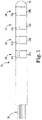
- Figure 1 illustrates a perspective view of a medical lead 10 in accordance with one embodiment.
- lead 10 includes, adjacent its distal end 12, four electrodes 20, 22, 24, 26. In other embodiments, more or less electrodes may be included.
- each of electrodes 20, 22, 24, 26 is segmented, such that each has a plurality of individually accessible electrode segments.
- first electrode 20 includes first, second, and third electrode segments 20a, 20b, and 20c;
- second electrode 22 includes first, second, and third electrode segments 22a, 22b, and 22c;
- third electrode 24 includes first, second, and third electrode segments 24a, 24b, and 24c;
- fourth electrode 26 includes first, second, and third electrode segments 26a, 26b, and 26c.
- each electrode segment a/b/c of each electrode 20, 22, 24, 26 extend radially about the outer diameter of lead 10, which is essentially an extended cylindrical shape in one embodiment, and each electrode segment a/b/c of each electrode 20, 22, 24, 26 are located along the same axial length of lead 10. Because the electrode segments are spaced radially about the circumference of lead 10, only some of the segments are visible in the side view of Figure 1 .
- some of the electrodes are single ring electrodes, without segmentation, while other of the electrodes are segmented in various combinations two, three, four or five or more segments.
- less than four electrodes are used, and in others more than four are used.
- the length of the electrode segments can be varied. In the illustration, each electrode segment has the same axial and radial length, but in other embodiments the relative axial and/or radial length of each can vary.
- lead 10 may be configured for use within a human body, such as within the vasculature. Once within a human body, each of electrode segments 20a/b/c, 22a/b/c, 24a/b/c, 26a/b/c may be used for directional stimulation or for positional feedback sensing.
- lead 10 includes electrode segments 20a/b/c, 22a/b/c, 24a/b/c, 26a/b/c, which only span a portion of the circumference of lead 10 (for example, 180°, 120°, 90° degrees or less), such that directional stimulation or positional feedback sensing can be much more precisely controlled relative to a given target within the human body.
- a plurality of conductors 30 are illustrated extending from lead 10.
- Each electrode segment 20a/b/c, 22a/b/c, 24a/b/c, 26a/b/c has a single corresponding conductor within the plurality of conductors 30, and each are electrically isolated from each other.
- the plurality of conductors 30 are available at the proximal end of lead 10 such that each of the 12 electrode segments 20a/b/c, 22a/b/c, 24a/b/c, 26a/b/c are electrically accessible at the proximal end of lead 10 via one conductor of the plurality of conductors 30.
- Medical lead 10 in accordance with embodiments described herein, allow for the manufacture of leads having increased density of electrode segments. Increased density of electrode segments is useful in a variety of applications.
- lead 10 can be used in deep brain stimulation (DBS), in which lead 10 delivers electrical pulses into one or several specific sites within the brain of a patient to treat various neurological disorders, such as chronic pain, tremors, Parkinson's disease, dystonia, epilepsy, depression, obsessive-compulsive disorder, and other disorders.
- lead 10 may be configured for spinal cord stimulation, peripheral nerve stimulation, dorsal root stimulation, cortical stimulation, ablation therapies, cardiac rhythm management leads, various catheter configurations for sensing, and various other therapies where directional sensing or stimulation are needed.
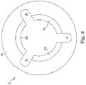
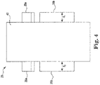
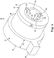
- FIGS 2-4 illustrate non-ground electrode 20 in perspective, front and side views, respectively, in accordance with one embodiment.
- the manufacture of lead 10 begins with a non-ground electrode, such as electrode 20, which includes electrode segments 20a/b/c and an electrode body 40.
- Electrode body 40 is provided with slots 42, which in one embodiment are spaced apart by approximately 120 degrees, such that each of electrode segments 20a/b/c are spaced from each other by a slot 42, as best illustrated in Figure 3 .
- slots 42 which in one embodiment are spaced apart by approximately 120 degrees, such that each of electrode segments 20a/b/c are spaced from each other by a slot 42, as best illustrated in Figure 3 .
- each of electrode segments 20a/b/c will be independently defined and can be readily electrically isolated from each other.
- This description of electrode 20 is similarly applicable to the configuration of electrodes 22, 24 and 26.
- Electrodes 20a/b/c are illustrated separated by about 120 degrees, but in other embodiments, a different amount of segments, such as two or four, can be used.
- the electrode segments are illustrated substantially equally sized and spaced, in other embodiments some segments can be smaller than others and some may be grouped closer together. For example, if four electrode segments are used, four slots are provided spaced apart by 90°. Also, in some embodiments, it may be desirable to have one radially longer electrode segment with two radially shorter segments. In one such embodiment, two slots can be separated by 120°, while the others are separated by 90°. Any number of combinations in various embodiments are possible.
- each of electrode segments 20a/b/c extend outward from electrode body 40 on both sides, as best illustrated in Figure 4 .
- electrode segments 20a/b/c extend outward a distance d 1 on a first side of electrode 20 and electrode segments 20a/b/c extend outward a distance d 2 on an opposite second side of electrode 20.
- distances d 1 and d 2 are the same, and in other embodiments, they are different. Configuring electrode segments 20a/b/c with these longer section can help facilitate coupling conductors and accommodating overmolded material, as will be further explained below.
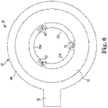
- FIGS 5-7 illustrate non-ground electrode 20 with overmold portions 45 in perspective, front and side views, respectively, in accordance with one embodiment.
- non-ground electrode 20 is overmolded with a plastic or similar polymer material in three main portions relative to non-ground electrode 20.
- overmold portions 45 include first overmold portion 50, second overmold portion 60, and third overmold portions 65.
- first overmold portion 50 is molded over the section of electrode segments 20a/b/c that extends out from electrode body 40 a distance w 1 on a first side of electrode 20.
- the distance w 1 that first overmold portion 50 extends out from electrode body 40 is the same as the distance d 1 that electrode segments 20a/b/c extend out from electrode body 40, such that they are substantially flush on a first side of electrode 20.
- first overmold portion 50 also has an outer diameter that is substantially the same as the outer diameter of electrode body 40 such that they are substantially flush on the outer diameter. In other embodiments, these respective dimensions can be different.
- second overmold portion 60 is molded over the section of electrode segments 20a/b/c that extends out from electrode body 40 a distance w 2 on a on a second side, opposite the first side. In one embodiment, the distance w 2 that second overmold portion 60 extends out from electrode body 40 is greater than the distance d 2 that electrode segments 20a/b/c extend out from electrode body 40, such electrode segments 20a/b/c are recessed relative to second overmold portion 60 (best seen in Figure 8 ). In one embodiment, second overmold portion 60 has an outer diameter that is slightly larger than the outer diameter of electrode body 40. In one embodiment, second overmold portion 60 further includes tab 62 extending out from its outer diameter.
- third overmold portions 65 substantially fill slots 42 between each of electrode segments 20a/b/c, extending between first and second overmold portions 50 and 60.
- third overmold portions 65 substantially fill slots 42, none of third overmold portions 65, nor any of overmold portions 45, cover the inner surfaces 21 of electrode segments 20a/b/c. Accordingly, these inner surfaces 21 of electrode segments 20a/b/c are readily able to accept conductor, as will be explained further, since they are free of overmold portions 45 or any molded or insulative material.
- each of third overmold portions 65 further include keys 52, for example, the third overmold portion 65 between first and second electrode segments 20a and 20b includes key 52b, the third overmold portion 65 between second and third electrode segments 20b and 20c includes key 52c, and third overmold portion 65 between third and first electrode segments 20c and 20a includes key 52a.
- keys 52a/b/c can be useful in the assembly of medical lead 10.
- each of keys 52a/b/c is precisely located relative to tab 62.
- tab 62 is illustrated at 0 degrees on the circular radius of electrode 20
- first key 52a is approximately 30 degrees advanced from 0 degrees
- second key 52b is approximately 150 degrees advanced from 0 degrees
- third key 52c is approximately 270 degrees advanced from 0 degrees.
- knowing the relative radial location of tab 62 also verifies the relative radial location of each of keys 52a/b/c. This is very useful in the process of attaching the plurality of conductors 30 to the electrode segments 20a/b/c for each of the electrodes.
- Electrodes are used in a lead, and where these electrodes each have a plurality of electrode segments, ensuring that each conductor is coupled to just one electrode segment and does not interfere with other conductors becomes quite challenging, especially when there are a large number of conductors within a very small diameter lead 10.
- Using the location of the keys 52 relative to the tabs 62 is useful where multiple electrodes are assembled together.
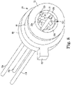
- Figure 8 illustrates a partially assembled electrode 20 in accordance with one embodiment.
- three conductors 70a, 70b and 70c, from the plurality of conductors 30, are illustrated coupled to non-ground electrode 20.
- first conductor 70a is coupled to an inner surface 21 of first electrode segment 20a
- second conductor 70b is coupled to an inner surface 21 of second electrode segment 20b
- third conductor 70c is coupled to an inner surface 21 of third electrode segment 20c.
- each conductor is coupled to only one electrode segment, and each electrode segment is electrically isolated from the others by third overmold portions 65 filling the slots 42 between them, each conductor is electrically coupled to just one specific electrode segment, such that the conductor can independently sense or energize one specific electrode segment.
- Conductors 70a/b/c can be attached to electrode segments 20a/b/c in a variety of ways, including welding, soldering, bonding, and gluing.
- each of the conductors 70a/b/c have an insulative cover 71.
- the cover portion is removed at the location of the electrode inner surface 21.
- the conductors are welded, the cover 71 is melted away in the process, thereby electrically coupling the conductor and electrode segment. Because the conductors are coupled to each of the electrodes individually, there are no blind welds, such that there are line of sight welds that are readily inspectable, which will ensure more quality welds of the conductors.
- each conductor is attached to a specific location within an electrode segment in order to accommodate the plurality of conductors within medical lead 10 when a plurality of electrodes are used.
- each conductor can be radially offset relative to each other conductor so no conductor interferes with another. Because of the combination of the keys 52 and tabs 62 of the overmold portions 45, these locations can be readily identified and controlled in the manufacturing process.
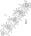
- Electrode assembly 80 in Figure 9 illustrates electrode assembly 80 in accordance with one embodiment. Electrode assembly 80 in Figure 9 is illustrated in an exploded form to illustrate some of the inner aspect features.
- electrode assembly 80 includes first through fourth non-ground electrodes 20/22/24/26.
- each of non-ground electrodes 20/22/24/26 are formed similar to that described above for electrode 20, such that each have electrode segments a/b/c and each have overmold portions 45 added.
- electrode assembly 80 can include more or less non-ground electrodes, such as two, three, five or six.
- each of the included non-ground electrodes can have the same number of segments or can have differing numbers of segments. For example, three non-ground electrodes may be included electrode assembly 80, a first having two electrode segments, a second having three electrode segments, and a third having four electrode segments, and at least one having overmold portions 45.
- each of non-ground electrodes 20/22/24/26 include first through third electrode segments a/b/c.
- One of the plurality of conductors 30 is attached to one (and only one) of the electrode segments, such that there are 12 conductors in the plurality of conductors 30, one for each of the electrode segments of each electrode. Because of the relatively large number of conductors that must fit into the relatively small diameter of non-ground electrodes 20/22/24/26, the radial attachment location of each conductor to a corresponding electrode segment should be coordinated to minimize interference and crowding between them.
- conductors 70a/b/c are coupled to first non-ground electrode 20.
- First conductor 70a is coupled to an inner surface of first electrode segment 20a at a location that is immediately adjacent second key 52b.
- second conductor 70b is coupled to an inner surface of second electrode segment 20b at a location that is immediately adjacent third key 52c.
- Third conductor 70c is then coupled to an inner surface of third electrode segment 20c at a location that is immediately adjacent first key 52a.
- conductors 72a/b/c are coupled to second non-ground electrode 22 at different relative radial locations.
- fourth conductor 72a is coupled to an inner surface of first electrode segment 22a at a location that is immediately adjacent first key 52a.
- Fifth conductor 72b is coupled to an inner surface of second electrode segment 22b at a location that is immediately adjacent second key 52b.
- Sixth conductor 72c is then coupled to an inner surface of third electrode segment 22c at a location that is immediately adjacent third key 52c.
- each of fourth-sixth conductors 72a/b/c are radially offset relative to each of first-third conductors 70a/b/c, such that the conductors will not interfere with each other as they pass from one end of the assembly 80 to the other end.
- Seventh-ninth conductors 74a/b/c and tenth-twelfth conductors 76a/b/c are similarly radially offset (radially between conductors 70a/b/c and conductors 72a/b/c in one embodiment) and respectively coupled to electrode segments 24a/b/c of third non-ground electrode 24 and electrode segments 26a/b/c of fourth non-ground electrode 26. Accordingly, all 12 of the plurality of conductors 70a/b/c, 72a/b/c, 74a/b/c and 76a/b/c are radially offset relative to each other such that all 12 conductors will not crowd or interfere with each other as they pass from one end of the electrode assembly 80 to the other end.
- each of tabs 62 can be placed into respective recesses of an assembly fixture such that the non-ground electrodes 20-26 cannot rotate during assembly.
- keys 52a/b/c can have tabs from the assembly fixture secured into them such that their relative radial location is known to the assembly fixture.
- each of the plurality of conductors 30 can be readily located at the appropriate radial location relative to each of the respective electrode segments so that none of the plurality of conductors 30 interfere with each other within the small diameter within each of the electrodes 20/22/24/26. Because of the known fixed relative radial location of tabs 62 and keys 52, the attachment of the conductors to the electrodes is highly repeatable and precise.
- each of electrodes 20/22/24/26 have respective conductors attached and then the electrodes with attached conductors are assembled together.
- Figure 8 illustrates conductors 70a/b/c respectively connected to electrode segments 20a/b/c of electrode 20, and similarly conductors 72a/b/c are respectively connected to electrode segments 22a/b/c of electrode 22, conductors 74a/b/c are respectively connected to electrode segments 24a/b/c of electrode 24, and conductors 76a/b/c are respectively connected to electrode segments 26a/b/c of electrode 26.
- the electrodes 20/22/24/26 with attached conductors are assemble together, much like shown in Figure 9 . Because the tabs 62 and respective keys 52 are appropriately aligned, in one embodiment, aligning each of the tabs will ensure the conductors are in the appropriate radial alignment.
- FIG. 10 illustrates electrode assembly 80 in accordance with one embodiment.
- Electrode assembly 80 in Figure 10 is illustrated in an assembled form after each of the plurality of conductors 30 have been coupled to a respective electrode segment and each of the electrodes 20/22/24/26 are assembled together.
- the distance w 2 that second overmold portion 60 extends out from each respective electrode body 40 is controlled in order to create the desired axial distance between each electrode 20/22/24/26.
- the axial distance between the electrodes and/or electrode segments is tailored to the particular application depending upon, for example, what tissue is being stimulated or sensed. By adjusting the distance w 2 of second overmold portion 60, the precise axial distance between the electrodes 20/22/24/26 is readily controlled in the assembly process.
- electrode assembly 80 is assembled as illustrated in Figure 10 , the entire assembly is reflowed such that all the connected portions are flowed over with the plastic material of overmold portions 45.
- the mold material flows into the inner diameter of the electrode assembly 80 and fills any voids between the plurality of conductors 30 and electrodes 20/22/24/26.
- the amount of molding material needed to effectively fill any gaps in the assembly may vary depending on the relative diameters and number of conductors. Accordingly, the overall diameter of overmold portion 60 can be increased or decreased as needed to ensure that the correct volume of molding material is available during the reflow process to ensure any voids are filled.
- the outer diameter of second overmold portion 60 is independent of the electrode body diameter 40, and is instead determined by the amount of molding material that is needed for filling the gaps and inner diameter of the electrode assembly 80.
- tabs 62 are aligned in the electrode assembly 80, tabs 62 are removed prior to reflow in order to provide a more uniform distribution of molding material during the reflow.
- Electrode assembly 80 can be reflowed in any of a variety of ways, such as a heat shrink tubing process or by heating within a die cavity.
- Such a grinding process can be, for example, a centerless grinding process where the electrode body 40 of each electrodes 20/22/24/26, along with the reflowed molding material on the outer diameter, is ground away from the external diameter of electrode assembly 80 inward until slots 42 are exposed on the outer lead diameter, thereby producing the electrode segments a/b/c for each of electrodes 20/22/24/26 on the outer diameter of medial lead 10.
- Manufacturing medical lead 10 to produce segmented electrodes using overmold portions with tabs and keys achieves an electrode array on a small diameter lead. In one embodiment, this creates a lead 10 having twelve discrete channels, which is not easily obtained with conventional techniques.
- a lead made with this process is sized with an outer diameter of 0.031 inches, making it appropriate for small animal or pediatric applications.
- FIG 11 illustrates a method of forming a segmented electrode lead, such as medical lead 10, in accordance with one embodiment.
- non-ground electrodes are formed.
- multiple non-ground electrodes such as non-ground electrode 20 of Figures 2-4 are formed.
- one, two, three, four or more non-ground electrodes are formed.
- overmold portions are added to at least one of the formed non-ground electrodes.
- the overmold portions include keys and tabs, such as the overmold portions 45 of Figures 5-7 .
- the keys and tabs are located at specific relative radial locations that are known.
- one conductor from a plurality of conductors are attached to one segment of the non-ground electrodes.
- One conductor is coupled to one segment, such as illustrated in Figure 8 .
- conductors are coupled at specific radial locations of each electrode segment by using the known radial locations of either keys or tabs or both.
- electrodes and conductors are assembled into an electrode or lead assembly and tabs are aligned, such as illustrated in Figures 9 and 10 .
- the axial distance between adjacent electrodes is determined by the width of the overmolded portion.
- the electrode assembly is reflowed, such that the overmolded material is flowed into the inner diameter of the electrode assembly and fills any voids between the plurality of conductors and electrodes.
- the reflowed assembly is then ground into medical lead 10, such as illustrated in Figure 1 .
- a centerless grinding process is used to grind down the outer diameter of the assembly until the electrodes are separated into electrode segments.
Landscapes
- Health & Medical Sciences (AREA)
- Engineering & Computer Science (AREA)
- Public Health (AREA)
- Veterinary Medicine (AREA)
- Biomedical Technology (AREA)
- Nuclear Medicine, Radiotherapy & Molecular Imaging (AREA)
- Radiology & Medical Imaging (AREA)
- Life Sciences & Earth Sciences (AREA)
- Animal Behavior & Ethology (AREA)
- General Health & Medical Sciences (AREA)
- Neurology (AREA)
- Heart & Thoracic Surgery (AREA)
- Neurosurgery (AREA)
- Cardiology (AREA)
- Psychology (AREA)
- Manufacturing & Machinery (AREA)
- Mechanical Engineering (AREA)
- Microelectronics & Electronic Packaging (AREA)
- Chemical & Material Sciences (AREA)
- Composite Materials (AREA)
- Orthopedic Medicine & Surgery (AREA)
- Electrotherapy Devices (AREA)
Claims (12)
- Verfahren zum Bilden eines medizinischen Leiters (10) für Implantationszwecke, umfassend:
Bilden einer Vielzahl von nicht geerdeten Elektroden (20/22/24/26), aber mindestens einer nicht geerdeten Elektrode, die eine Vielzahl von Elektrodensegmenten (20a/b/c, 22a/b/c, 24a/b/c, 26a/b/c) aufweist; dadurch gekennzeichnet, dass das Verfahren ferner umfasst:Bilden von Überformabschnitten (45) für die mindestens eine der Vielzahl von nicht geerdeten Elektroden (20/22/24/26), wobei die Überformabschnitte Passnuten (52) und Passfedern (62) umfassen;Anfügen eines einer Vielzahl von Leitern (30) an ein Elektrodensegment der mindestens einen nicht geerdeten Elektrode unter Verwendung der Passnuten (52) und Passfedern (62);Montieren der nicht geerdeten Elektroden (20/22/24/26) und der Vielzahl von Leitern (30) in die Elektrodenanordnung (80);Rückschmelzen der Überformabschnitte (45); undSchleifen der rückgeschmolzenen Elektrodenanordnung, um den medizinischen Leiter (10) zu bilden, wobei die Leiter (30) an spezifischen Stellen der Elektrodensegmente (20a/b/c, 22a/b/c, 24a/b/c, 26a/b/c) angebracht sind und die spezifische Stelle mindestens teilweise durch die relative radiale Position der Passnuten (52) und Passfedern (62) bestimmt wird. - Verfahren nach Anspruch 1, wobei die Passnuten (52) und Passfedern (62) sich an bestimmten festen radialen Stellen relativ zueinander befinden.
- Verfahren nach einem vorstehenden Anspruch, wobei das Bilden der Überformabschnitte (45) ferner das Bilden eines ersten Überformabschnitts (50) auf einer ersten Seite der mindestens einen nicht geerdeten Elektrode, das Bilden eines zweiten Überformabschnitts (60) auf einer zweiten Seite der mindestens einen nicht geerdeten Elektrode, die der ersten Seite gegenüberliegt, und das Bilden dritter Überformabschnitte (65), die sich zwischen dem ersten und dem zweiten Überformabschnitt (50/60) und innerhalb von Nuten (42) in der mindestens einen nicht geerdeten Elektrode ((20/22/24/26) befinden, umfasst.
- Verfahren nach einem vorstehenden Anspruch, wobei der axiale Abstand zwischen zwei benachbarten Elektroden (20/22/24/26) mindestens teilweise durch die Breite des zweiten Überformabschnitts (60) bestimmt wird.
- Verfahren nach einem vorstehenden Anspruch, wobei das Bilden des zweiten Überformabschnitts (60) das Bilden mindestens einer Passfeder (62) oder das Bilden der dritten Überformabschnitte (65) das Bilden mindestens einer Passnut (52) umfasst.
- Verfahren nach einem vorstehenden Anspruch, wobei das Anbringen einer Vielzahl von Leitern (30) an ein Elektrodensegment der nicht geerdeten Elektroden das Lokalisieren einer der Passnuten (52) und der Passfedern (62) innerhalb einer Montagehalterung einschließt.
- Verfahren nach einem vorstehenden Anspruch, wobei die Menge an Material, die während des Rückschmelzens der Überformabschnitte (45) zurückfließt, mindestens teilweise abhängig vom Durchmesser des zweiten Überformabschnitts (60) ist.
- Verfahren nach einem vorstehenden Anspruch, wobei das Rückschmelzen der Überformabschnitte (45) einen Wärmeschrumpfschlauchprozess umfasst oder wobei vor dem Rückschmelzen der Überformabschnitte (45) alle Passfedern (62) entfernt werden.
- Elektrodenanordnung (80) zum Herstellen eines Elektrodenleiters (10), wobei die Elektrodenanordnung (80) umfasst:
eine Vielzahl von nicht geerdeten Elektroden (20/22/24/26), mindestens eine nicht geerdete Elektrode, die eine Vielzahl von Elektrodensegmenten (20a/b/c, 22a/b/c, 24a/b/c, 26a/b/c) aufweisen, dadurch gekennzeichnet, dass die Elektrodenanordnung (80) ferner umfasst:Überformabschnitte (45) auf mindestens einer der Vielzahl von nicht geerdeten Elektroden (20/22/24/26), wobei die Überformabschnitte (45) Passnuten (52) und Passfedern (62) umfassen; undeine Vielzahl von Leitern (30), wobei ein Leiter aus der Vielzahl von Leitern mit einem Elektrodensegment der mindestens einen nicht geerdeten Elektrode an einer Stelle verbunden ist, die mindestens teilweise auf der relativen radialen Lage der Passnuten (52) und der Passfedern (62) basiert. - Elektrodenanordnung (80) nach einem vorstehenden Anspruch, wobei mindestens eine aus der Vielzahl von nicht geerdeten Elektroden Nuten (42) umfasst, wodurch die Vielzahl von Elektrodensegmenten zwischen den Nuten (42) bestimmt wird.
- Elektrodenanordnung (80) nach einem vorstehenden Anspruch, wobei die Überformabschnitte einen ersten Überformabschnitt (50) auf einer ersten Seite der mindestens einen nicht geerdeten Elektrode, einen zweiten Überformabschnitt (60) auf einer zweiten Seite der mindestens einen nicht geerdeten Elektrode, die der ersten Seite gegenüberliegt, und dritte Überformabschnitte (65), die sich zwischen dem ersten und dem zweiten Überformabschnitt (50/60) und innerhalb von Nuten (42) in der mindestens einen nicht geerdeten Elektrode befinden, umfassen.
- Elektrodenanordnung (80) nach einem vorstehenden Anspruch, wobei der zweite Überformabschnitt (60) mindestens eine Passnut (62) umfasst oder wobei die dritten Überformabschnitte (65) mindestens eine Passfeder (52) umfassen.
Applications Claiming Priority (1)
| Application Number | Priority Date | Filing Date | Title |
|---|---|---|---|
| US201862785968P | 2018-12-28 | 2018-12-28 |
Publications (2)
| Publication Number | Publication Date |
|---|---|
| EP3673951A1 EP3673951A1 (de) | 2020-07-01 |
| EP3673951B1 true EP3673951B1 (de) | 2022-05-04 |
Family
ID=68944491
Family Applications (1)
| Application Number | Title | Priority Date | Filing Date |
|---|---|---|---|
| EP19217292.2A Active EP3673951B1 (de) | 2018-12-28 | 2019-12-18 | Umgossene segmentierte elektrode |
Country Status (3)
| Country | Link |
|---|---|
| US (1) | US11458300B2 (de) |
| EP (1) | EP3673951B1 (de) |
| CN (1) | CN111375125A (de) |
Families Citing this family (1)
| Publication number | Priority date | Publication date | Assignee | Title |
|---|---|---|---|---|
| CN119838136B (zh) * | 2025-02-14 | 2026-07-07 | 景昱医疗科技(苏州)股份有限公司 | 用于安装电极触点的分体式支架、方向电极、植入式刺激系统 |
Family Cites Families (136)
| Publication number | Priority date | Publication date | Assignee | Title |
|---|---|---|---|---|
| US3939843A (en) | 1974-03-04 | 1976-02-24 | Medtronic, Inc. | Transvenous electrode |
| US5000194A (en) | 1988-08-25 | 1991-03-19 | Cochlear Corporation | Array of bipolar electrodes |
| US5199443A (en) | 1991-03-26 | 1993-04-06 | Empi, Inc. | Incontinence electrode apparatus |
| US5843148A (en) | 1996-09-27 | 1998-12-01 | Medtronic, Inc. | High resolution brain stimulation lead and method of use |
| US6201981B1 (en) | 1997-06-04 | 2001-03-13 | Nihon Kohden Corporation | Electrode for measuring biomedical signal and electrode support device for measuring a biomedical signal |
| US6249708B1 (en) | 1997-08-26 | 2001-06-19 | Angeion Corporation | Fluted channel construction for a multi-conductor catheter lead |
| US6078830A (en) | 1997-10-01 | 2000-06-20 | Ep Technologies, Inc. | Molded catheter distal end assembly and process for the manufacture thereof |
| US6185465B1 (en) | 1998-02-25 | 2001-02-06 | Seung Kee Mo | Vaginal electrode for urinary incontinence treatment |
| US6052625A (en) | 1998-11-09 | 2000-04-18 | Medtronic, Inc. | Extractable implantable medical lead |
| US6216045B1 (en) | 1999-04-26 | 2001-04-10 | Advanced Neuromodulation Systems, Inc. | Implantable lead and method of manufacture |
| DE10008918A1 (de) | 2000-02-25 | 2001-08-30 | Biotronik Mess & Therapieg | Ablationskatheter zur Erzeugung linearer Läsionen in Herzmuskelgewebe |
| EP2027816B1 (de) | 2000-07-19 | 2012-06-20 | Innovamédica S.A. de C.V. | Katheter zur ischämischer Überwachung von Schleimhautschäden von viskosen Hohlorgane |
| US20030236562A1 (en) | 2000-10-10 | 2003-12-25 | Kuzma Janusz A. | Band type multicontact electrode and method of making the same |
| DE60124948T2 (de) | 2000-12-07 | 2007-09-20 | Medtronic, Inc., Minneapolis | Leitungen für die gerichtete Hirnstimulation und-aufzeichnung |
| US6600956B2 (en) | 2001-08-21 | 2003-07-29 | Cyberonics, Inc. | Circumneural electrode assembly |
| US6999821B2 (en) | 2002-01-18 | 2006-02-14 | Pacesetter, Inc. | Body implantable lead including one or more conductive polymer electrodes and methods for fabricating same |
| US20030199951A1 (en) | 2002-04-22 | 2003-10-23 | Pardo Xavier E. | Implantable lead with improved conductor lumens |
| US7203548B2 (en) | 2002-06-20 | 2007-04-10 | Advanced Bionics Corporation | Cavernous nerve stimulation via unidirectional propagation of action potentials |
| US7319906B2 (en) | 2002-09-19 | 2008-01-15 | Advanced Bionics Corporation | Cochlear implant electrode and method of making same |
| US6925334B1 (en) | 2003-08-04 | 2005-08-02 | Pacesetter, Inc. | Implantable medical lead having multiple, jointly insulated electrical conductors |
| US20050038489A1 (en) | 2003-08-14 | 2005-02-17 | Grill Warren M. | Electrode array for use in medical stimulation and methods thereof |
| US7437197B2 (en) | 2003-10-23 | 2008-10-14 | Medtronic, Inc. | Medical lead and manufacturing method therefor |
| US20050159799A1 (en) | 2003-11-25 | 2005-07-21 | Advanced Neuromodulation Systems, Inc. | Percutaneous-insertion needle and method of implanting a lead |
| US7212868B2 (en) | 2004-03-30 | 2007-05-01 | Cardiac Pacemakers, Inc. | Electrode and insulation assembly for a lead and method therefor |
| US7844343B2 (en) | 2004-03-30 | 2010-11-30 | Medtronic, Inc. | MRI-safe implantable medical device |
| US7715926B2 (en) | 2004-04-23 | 2010-05-11 | Medtronic, Inc. | Medical device conductor junctions |
| US7489971B1 (en) | 2004-06-05 | 2009-02-10 | Advanced Neuromodulation Systems, Inc. | Notched electrode for electrostimulation lead |
| US7891085B1 (en) | 2005-01-11 | 2011-02-22 | Boston Scientific Neuromodulation Corporation | Electrode array assembly and method of making same |
| ATE448830T1 (de) | 2005-01-31 | 2009-12-15 | Medtronic Inc | Verfahren zur herstellung einer medizinischen leitung |
| US7551967B1 (en) | 2005-05-19 | 2009-06-23 | Pacesetter, Inc. | Implantable medical leads and devices having carbon nanotube-based anti-electrostatic coatings and methods for making such leads and devices |
| US20070005053A1 (en) | 2005-06-30 | 2007-01-04 | Dando Jeremy D | Ablation catheter with contoured openings in insulated electrodes |
| US7917213B2 (en) | 2005-11-04 | 2011-03-29 | Kenergy, Inc. | MRI compatible implanted electronic medical lead |
| US7654843B2 (en) | 2006-02-28 | 2010-02-02 | Medtronic, Inc. | Connector assembly with internal seals and manufacturing method |
| US20070282411A1 (en) | 2006-03-31 | 2007-12-06 | Brian Franz | Compliant electrical stimulation leads and methods of fabrication |
| US8892214B2 (en) | 2006-04-28 | 2014-11-18 | Medtronic, Inc. | Multi-electrode peripheral nerve evaluation lead and related system and method of use |
| US20070255320A1 (en) | 2006-04-28 | 2007-11-01 | Cyberonics, Inc. | Method and apparatus for forming insulated implantable electrodes |
| US7738966B2 (en) | 2006-08-21 | 2010-06-15 | Medtronic, Inc. | Features for routing conductors in medical electrical lead electrode assemblies |
| WO2008051122A1 (en) | 2006-10-25 | 2008-05-02 | St. Jude Medical Ab | A medical implantable lead |
| US7717754B2 (en) | 2006-12-07 | 2010-05-18 | Medtronic, Inc. | Connector assembly with internal seals and manufacturing method |
| US7996092B2 (en) | 2007-01-16 | 2011-08-09 | Ndi Medical, Inc. | Devices, systems, and methods employing a molded nerve cuff electrode |
| DE102007006089A1 (de) | 2007-02-07 | 2008-08-14 | Biotronik Crm Patent Ag | Elektrodenleitung und Anschlussstück für einen implantierbaren Herzstimulator |
| EP2155319B1 (de) | 2007-04-20 | 2018-08-08 | Medtronic, Inc. | Implantierbare medizinische elektrische leitung und konnektor-anordnung |
| EP2144665B2 (de) | 2007-04-26 | 2024-07-10 | Medtronic, Inc. | Implantierbare medizinische leitung mit mehreren elektrodenkonfigurationen |
| US7668601B2 (en) | 2007-04-26 | 2010-02-23 | Medtronic, Inc. | Implantable medical lead with multiple electrode configurations |
| WO2009065171A1 (en) | 2007-11-19 | 2009-05-28 | Cochlear Limited | Electrode array for a cochlear implant |
| US8364284B2 (en) | 2008-09-15 | 2013-01-29 | Boston Scientific Neuromodulation Corporation | Implantable electric stimulation system and methods of making and using |
| US7798864B2 (en) | 2008-03-12 | 2010-09-21 | Boston Scientific Neuromodulation Corporation | Low-profile connector for a neurostimulation lead |
| US8244372B1 (en) | 2008-04-01 | 2012-08-14 | Advanced Neuromodulation Systems, Inc. | Electrical stimulation lead with stiffeners having varying stiffness zones |
| US9192758B2 (en) | 2008-04-17 | 2015-11-24 | Medtronic, Inc. | Extensible implantable medical lead with sigmoidal conductors |
| DE102008032500A1 (de) | 2008-07-05 | 2010-01-14 | Osypka, Peter, Dr. Ing. | Medizinischer Katheter mit mehreren Polen oder Elektroden |
| US8712542B2 (en) | 2008-11-04 | 2014-04-29 | Boston Scientific Neuromodulation Corporation | Deposited conductive layers for leads of implantable electric stimulation systems and methods of making and using |
| US8250754B2 (en) | 2008-11-29 | 2012-08-28 | Medtronic, Inc. | Method of manufacturing a medical electrical lead with insert-molded electrode |
| US20100137964A1 (en) | 2008-11-29 | 2010-06-03 | Medtronic, Inc. | Medical electrical lead joints and methods of manufacture |
| US8442658B2 (en) | 2009-01-30 | 2013-05-14 | Pacesetter, Inc. | Crimp-through crimp connector for connecting a conductor cable and an electrode of an implantable cardiac electrotherapy lead |
| US20100210146A1 (en) | 2009-02-18 | 2010-08-19 | Pacesetter, Inc. | Lead connector end and method of manufacture |
| US8478423B2 (en) | 2009-04-07 | 2013-07-02 | Boston Scientific Neuromodulation Corporation | Insulator layers for leads of implantable electric stimulation systems and methods of making and using |
| US8320988B2 (en) | 2009-04-09 | 2012-11-27 | Axelgaard Manufacturing Co., Ltd. | Multi-electrode strung on a common connector |
| US8046909B2 (en) | 2009-04-24 | 2011-11-01 | Advanced Neuromodulation Systems, Inc. | Method of fabricating stimulation lead |
| US8250755B2 (en) | 2009-04-24 | 2012-08-28 | Advanced Neuromodulation Systems, Inc. | Process for fabricating a medical lead |
| US8225504B2 (en) | 2009-04-24 | 2012-07-24 | Advanced Neuromodulation Systems, Inc. | Medical leads with segmented electrodes and methods of fabrication thereof |
| US20100331942A1 (en) | 2009-06-29 | 2010-12-30 | Pacesetter, Inc. | Mri compatible implantable medical lead and method of making same |
| US8322026B2 (en) | 2009-06-29 | 2012-12-04 | Boston Scientific Neuromodulation Corporation | Method for forming a lead |
| US8340783B2 (en) | 2009-06-30 | 2012-12-25 | Medtronic, Inc. | Implantable medical device lead with selectively exposed electrodes and reinforcement member |
| US8875391B2 (en) | 2009-07-07 | 2014-11-04 | Boston Scientific Neuromodulation Corporation | Methods for making leads with radially-aligned segmented electrodes for electrical stimulation systems |
| US8887387B2 (en) * | 2009-07-07 | 2014-11-18 | Boston Scientific Neuromodulation Corporation | Methods of manufacture of leads with a radially segmented electrode array |
| US8321033B2 (en) | 2009-07-13 | 2012-11-27 | Pacesetter, Inc. | Implantable medical lead having passive lock mechanical body terminations |
| US8816711B2 (en) | 2009-08-26 | 2014-08-26 | United Technologies Corporation | Electrical probe assembly |
| WO2011028809A1 (en) | 2009-09-01 | 2011-03-10 | Advanced Neuromodulation Systems, Inc. | Medical leads with segmented electrodes and methods of fabrication thereof |
| US9054436B2 (en) | 2009-09-30 | 2015-06-09 | Advanced Neuromodulation Systems, Inc. | Method of fabricating stimulation lead for applying electrical stimulation to tissue of a patient |
| US20110077699A1 (en) | 2009-09-30 | 2011-03-31 | John Swanson | Medical leads with segmented electrodes and methods of fabrication thereof |
| US8171621B2 (en) | 2009-09-30 | 2012-05-08 | Advanced Neuromodulation Systems, Inc. | Methods of fabrication of a simulation lead |
| US8391985B2 (en) | 2009-11-30 | 2013-03-05 | Boston Scientific Neuromodulation Corporation | Electrode array having concentric windowed cylinder electrodes and methods of making the same |
| US8874232B2 (en) | 2009-11-30 | 2014-10-28 | Boston Scientific Neuromodulation Corporation | Electrode array having concentric split ring electrodes and methods of making the same |
| US8382529B2 (en) | 2009-12-30 | 2013-02-26 | Cardiac Pacemakers, Inc. | Terminal connector assembly for a medical electrical lead |
| EP2519307B1 (de) | 2009-12-30 | 2015-09-09 | Cardiac Pacemakers, Inc. | Implantierbare elektroden mit einheitlicher silikonkomponente |
| US9278223B2 (en) | 2010-01-28 | 2016-03-08 | Medtronic, Inc. | Lead connector with glass braze |
| WO2011123608A1 (en) | 2010-04-02 | 2011-10-06 | Boston Scientific Neuromodulation Corporation | Directional lead assembly |
| US8666494B2 (en) | 2010-04-29 | 2014-03-04 | Donatelle Plastics, Inc. | Header for implantable pulse generator and method of making same |
| US8972995B2 (en) | 2010-08-06 | 2015-03-03 | Sonics, Inc. | Apparatus and methods to concurrently perform per-thread as well as per-tag memory access scheduling within a thread and across two or more threads |
| US8583237B2 (en) | 2010-09-13 | 2013-11-12 | Cranial Medical Systems, Inc. | Devices and methods for tissue modulation and monitoring |
| AU2011305914B2 (en) | 2010-09-21 | 2016-05-12 | Boston Scientific Neuromodulation Corporation | Systems and methods for making and using radially-aligned segmented electrodes for leads of electrical stimulation systems |
| EP2654877B1 (de) | 2010-12-20 | 2016-08-24 | Cardiac Pacemakers, Inc. | Elektrode mit leitfähigem polymerleiter |
| US8700179B2 (en) | 2011-02-02 | 2014-04-15 | Boston Scientific Neuromodulation Corporation | Leads with spiral of helical segmented electrode arrays and methods of making and using the leads |
| EP2500998B1 (de) | 2011-03-16 | 2014-06-11 | Sorin CRM SAS | Elektrischer Anschlussstift für multipolare Sonde einer aktiven implantierbaren medizinischen Vorrichtung |
| US8567055B2 (en) | 2011-03-18 | 2013-10-29 | Medtronic, Inc. | Method of assembling an in-line connector terminal |
| US8340759B2 (en) | 2011-04-22 | 2012-12-25 | Medtronic, Inc. | Large-pitch coil configurations for a medical device |
| JP2014521400A (ja) | 2011-07-07 | 2014-08-28 | カーディアック ペースメイカーズ, インコーポレイテッド | 植え込み型医療装置リード用の絶縁および安定機構 |
| US9138576B2 (en) | 2011-10-28 | 2015-09-22 | Medtronic, Inc. | Lead end having inner support |
| US10076657B2 (en) | 2011-10-28 | 2018-09-18 | Medtronic, Inc. | Lead end having slotted member |
| US9421362B2 (en) | 2011-10-28 | 2016-08-23 | Medtronic, Inc. | Modular lead end |
| US8886336B2 (en) | 2011-11-29 | 2014-11-11 | Cardiac Pacemakers, Inc. | Implantable medical leads having oscillating cable conductor lumens |
| EP2793996B1 (de) | 2011-12-21 | 2016-02-24 | Cardiac Pacemakers, Inc. | Richtungsfunktionen für implantierbare medizinische leitungen |
| WO2013112144A1 (en) | 2012-01-25 | 2013-08-01 | Advanced Bionics Ag | Intraneural implant |
| EP2830700B1 (de) | 2012-03-30 | 2017-09-27 | Boston Scientific Neuromodulation Corporation | Leitungen mit röntgenstrahlfluoreszenzkapseln zur elektrodenidentifizierung sowie verfahren zur herstellung und verwendung |
| US8784714B2 (en) | 2012-03-30 | 2014-07-22 | Cardiac Pacemakers, Inc. | Steroid eluting collar undermold |
| US9878148B2 (en) | 2012-04-17 | 2018-01-30 | Boston Scientific Neuromodulation Corporation | Lead with contact end conductor guide and methods of making and using |
| WO2013162775A2 (en) * | 2012-04-27 | 2013-10-31 | Medtronic, Inc. | Structures and techniques for medical lead fabrication |
| JP2015519124A (ja) | 2012-05-08 | 2015-07-09 | アンジオメトリックス コーポレーション | ガイドワイヤ組立方法および装置 |
| US9545207B2 (en) | 2012-07-25 | 2017-01-17 | Cardiac Pacemakers, Inc. | Temporary implantable medical electrical stimulation lead |
| EP2877236B1 (de) | 2012-07-26 | 2023-03-29 | Medtronic, Inc. | Implantierbare medizinische elektroden |
| US9993637B2 (en) | 2012-08-27 | 2018-06-12 | Boston Scientific Neuromodulation Corporation | Electrical stimulation lead with junction and methods of making and using |
| EP2719422B1 (de) | 2012-10-12 | 2015-02-18 | Sorin CRM SAS | Implantierbare multipolare Mikrosonde zur Erfassung/Stimulation |
| US9375563B2 (en) | 2012-12-06 | 2016-06-28 | Boston Scientific Neuromodulation Corporation | Systems and methods of forming contact assemblies for leads of electrical stimulation systems |
| US9101755B2 (en) | 2012-12-27 | 2015-08-11 | Boston Scientific Neuromodulation Corporation | Systems and methods for making and using contact assemblies for leads of electrical stimulation systems |
| US9209544B2 (en) | 2013-01-31 | 2015-12-08 | Heraeus Precious Metals Gmbh & Co. Kg | Lead connector with distal frame and method of manufacture |
| US9472916B2 (en) | 2013-03-14 | 2016-10-18 | Medtronic, Inc. | Distal connector assemblies for medical lead extensions |
| JP6212814B2 (ja) | 2013-05-21 | 2017-10-18 | 国立研究開発法人科学技術振興機構 | 多点プローブ及びそれを構成する電子接点シート、多点プローブアレイ並びに多点プローブの製造方法 |
| US9615760B2 (en) | 2013-06-17 | 2017-04-11 | Biosense Webster (Israel), Ltd. | Multiple bipolar sampling |
| WO2015006239A1 (en) | 2013-07-12 | 2015-01-15 | Boston Scientific Neuromodulation Corporation | Leads with segmented electrodes and methods of making and using the leads |
| AU2014293477A1 (en) | 2013-07-22 | 2016-01-28 | Boston Scientific Neuromodulation Corporation | Methods of manufacturing molded segmented electrode leads |
| EP3038701A1 (de) | 2013-08-27 | 2016-07-06 | Advanced Bionics AG | Elektroden und verfahren für ein asymmetrisches cochlea-implantat |
| US9089689B2 (en) | 2013-08-30 | 2015-07-28 | Boston Scientific Neuromodulation Corporation | Methods of making segmented electrode leads using flanged carrier |
| US9421360B2 (en) | 2013-10-17 | 2016-08-23 | Pacesetter, Inc. | Medical device lead assembly having integrated pressure-resisting member |
| EP2873435B1 (de) | 2013-11-14 | 2016-05-18 | Beacmed S.r.L. | Perinealsonde |
| US9775988B2 (en) | 2013-12-02 | 2017-10-03 | Boston Scientific Neuromodulation Corporation | Electrical stimulation leads with helically arranged electrodes and methods of making and using |
| US9370653B2 (en) | 2013-12-05 | 2016-06-21 | Advanced Neuromodulation Systems, Inc. | Medical leads with segmented electrodes and methods of fabrication thereof |
| US9101776B2 (en) | 2013-12-18 | 2015-08-11 | Medtronic, Inc. | Implantable medical electrical lead connector assemblies and methods of manufacture |
| US9106004B2 (en) | 2013-12-19 | 2015-08-11 | Medtronic, Inc. | Implantable medical electrical leads and connector assemblies thereof |
| US20150202432A1 (en) | 2014-01-22 | 2015-07-23 | Pacesetter, Inc. | Electrode structure for deep brain stimulation |
| WO2015134612A1 (en) | 2014-03-05 | 2015-09-11 | Medtronic, Inc. | Implantable medical electrical lead connector assemblies and methods of manufacture |
| US9757555B2 (en) | 2014-04-24 | 2017-09-12 | Medtronic, Inc. | Pre-molded sub-assemblies for implantable medical leads |
| ES2867298T3 (es) | 2014-08-15 | 2021-10-20 | Axonics Modulation Tech Inc | Estructura implantable de fijación de derivación para estimulación nerviosa destinada a aliviar disfunción vesical y otras indicaciones |
| US9474894B2 (en) | 2014-08-27 | 2016-10-25 | Aleva Neurotherapeutics | Deep brain stimulation lead |
| US10765858B2 (en) | 2014-11-05 | 2020-09-08 | Medtronic, Inc. | Extravascular lead designs for optimized pacing and sensing having segmented, partially electrically insulated defibrillation coils |
| US9561362B2 (en) | 2014-11-10 | 2017-02-07 | Boston Scientific Neuromodulation Corporation | Systems and methods for making and using improved contact arrays for electrical stimulation systems |
| US9800010B2 (en) | 2015-04-08 | 2017-10-24 | Pacesetter, Inc. | Implantable lead assembly |
| US9364659B1 (en) | 2015-04-27 | 2016-06-14 | Dantam K. Rao | Smart lead for deep brain stimulation |
| US20170189674A1 (en) | 2016-01-04 | 2017-07-06 | Medtronic, Inc. | Medical electrical lead |
| US11478652B2 (en) | 2016-03-17 | 2022-10-25 | Pacesetter Inc. | Implantable medical device with modular injection molded header assembly and related methods of manufacture |
| US10124161B2 (en) | 2016-03-31 | 2018-11-13 | Boston Scientific Neuromodulation Corporation | Neurostimulation lead with conductive elements and methods for making the same |
| US10449353B2 (en) | 2016-04-28 | 2019-10-22 | Medtronic, Inc. | Electrode assemblies, methods, and components thereof for implantable medical electrical leads |
| EP3284509B1 (de) | 2016-08-15 | 2020-10-07 | Heraeus Medical Components, LLC | Segmentierte elektrode und verfahren |
| US11154713B2 (en) | 2016-11-11 | 2021-10-26 | Medtronic, Inc. | Electrode structure for implantable medical leads |
| WO2018102695A2 (en) | 2016-12-01 | 2018-06-07 | Advanced Bionecs Ag | Cochlear implants including electrode arrays and methods of making the same |
| US20190067719A1 (en) | 2017-08-22 | 2019-02-28 | GM Global Technology Operations LLC | Method for manufactring an overmolded unitized electrode assembly |
| US10953221B2 (en) | 2017-08-30 | 2021-03-23 | Medtronic, Inc. | Medical lead with segmented electrodes |
-
2019
- 2019-12-18 EP EP19217292.2A patent/EP3673951B1/de active Active
- 2019-12-18 US US16/718,368 patent/US11458300B2/en active Active
- 2019-12-30 CN CN201911392615.2A patent/CN111375125A/zh active Pending
Also Published As
| Publication number | Publication date |
|---|---|
| US20200206494A1 (en) | 2020-07-02 |
| EP3673951A1 (de) | 2020-07-01 |
| CN111375125A (zh) | 2020-07-07 |
| US11458300B2 (en) | 2022-10-04 |
Similar Documents
| Publication | Publication Date | Title |
|---|---|---|
| US20240366932A1 (en) | Medical leads with segmented electrodes and methods of fabrication thereof | |
| JP5834065B2 (ja) | 指向性リード線アセンブリ | |
| JP5808813B2 (ja) | 電気刺激リード及び刺激デバイスのためのリードを形成する方法 | |
| JP5793190B2 (ja) | 脳刺激装置を製造する方法 | |
| EP3154625B1 (de) | Leitungen mit elektrodenträgern für segmentierte elektroden und verfahren zur herstellung und verwendung | |
| US9162048B2 (en) | Systems and methods for making and using tip electrodes for leads of electrical stimulation systems | |
| EP3077039B1 (de) | Verfahren zur herstellung von elektrischen stimulationsleitungen mit spiralförmig angeordneten elektroden | |
| EP3736018B1 (de) | Leitungskörper mit hoher dichte und verfahren | |
| JP5612090B2 (ja) | 刺激装置用のリードを作成する方法 | |
| US9364659B1 (en) | Smart lead for deep brain stimulation | |
| EP3284509B1 (de) | Segmentierte elektrode und verfahren | |
| JP2023503352A (ja) | 神経インタフェースシステム | |
| US20160144164A1 (en) | Implantable medical lead with protective tubing element | |
| US11458300B2 (en) | Overmolded segmented electrode |
Legal Events
| Date | Code | Title | Description |
|---|---|---|---|
| PUAI | Public reference made under article 153(3) epc to a published international application that has entered the european phase |
Free format text: ORIGINAL CODE: 0009012 |
|
| STAA | Information on the status of an ep patent application or granted ep patent |
Free format text: STATUS: REQUEST FOR EXAMINATION WAS MADE |
|
| 17P | Request for examination filed |
Effective date: 20191218 |
|
| AK | Designated contracting states |
Kind code of ref document: A1 Designated state(s): AL AT BE BG CH CY CZ DE DK EE ES FI FR GB GR HR HU IE IS IT LI LT LU LV MC MK MT NL NO PL PT RO RS SE SI SK SM TR |
|
| AX | Request for extension of the european patent |
Extension state: BA ME |
|
| GRAP | Despatch of communication of intention to grant a patent |
Free format text: ORIGINAL CODE: EPIDOSNIGR1 |
|
| STAA | Information on the status of an ep patent application or granted ep patent |
Free format text: STATUS: GRANT OF PATENT IS INTENDED |
|
| RIC1 | Information provided on ipc code assigned before grant |
Ipc: A61N 1/05 20060101AFI20211029BHEP |
|
| INTG | Intention to grant announced |
Effective date: 20211130 |
|
| GRAS | Grant fee paid |
Free format text: ORIGINAL CODE: EPIDOSNIGR3 |
|
| GRAA | (expected) grant |
Free format text: ORIGINAL CODE: 0009210 |
|
| STAA | Information on the status of an ep patent application or granted ep patent |
Free format text: STATUS: THE PATENT HAS BEEN GRANTED |
|
| AK | Designated contracting states |
Kind code of ref document: B1 Designated state(s): AL AT BE BG CH CY CZ DE DK EE ES FI FR GB GR HR HU IE IS IT LI LT LU LV MC MK MT NL NO PL PT RO RS SE SI SK SM TR |
|
| REG | Reference to a national code |
Ref country code: GB Ref legal event code: FG4D |
|
| REG | Reference to a national code |
Ref country code: CH Ref legal event code: EP |
|
| REG | Reference to a national code |
Ref country code: AT Ref legal event code: REF Ref document number: 1488380 Country of ref document: AT Kind code of ref document: T Effective date: 20220515 |
|
| REG | Reference to a national code |
Ref country code: IE Ref legal event code: FG4D Ref country code: DE Ref legal event code: R096 Ref document number: 602019014443 Country of ref document: DE |
|
| REG | Reference to a national code |
Ref country code: LT Ref legal event code: MG9D |
|
| REG | Reference to a national code |
Ref country code: NL Ref legal event code: MP Effective date: 20220504 |
|
| REG | Reference to a national code |
Ref country code: AT Ref legal event code: MK05 Ref document number: 1488380 Country of ref document: AT Kind code of ref document: T Effective date: 20220504 |
|
| PG25 | Lapsed in a contracting state [announced via postgrant information from national office to epo] |
Ref country code: SE Free format text: LAPSE BECAUSE OF FAILURE TO SUBMIT A TRANSLATION OF THE DESCRIPTION OR TO PAY THE FEE WITHIN THE PRESCRIBED TIME-LIMIT Effective date: 20220504 Ref country code: PT Free format text: LAPSE BECAUSE OF FAILURE TO SUBMIT A TRANSLATION OF THE DESCRIPTION OR TO PAY THE FEE WITHIN THE PRESCRIBED TIME-LIMIT Effective date: 20220905 Ref country code: NO Free format text: LAPSE BECAUSE OF FAILURE TO SUBMIT A TRANSLATION OF THE DESCRIPTION OR TO PAY THE FEE WITHIN THE PRESCRIBED TIME-LIMIT Effective date: 20220804 Ref country code: NL Free format text: LAPSE BECAUSE OF FAILURE TO SUBMIT A TRANSLATION OF THE DESCRIPTION OR TO PAY THE FEE WITHIN THE PRESCRIBED TIME-LIMIT Effective date: 20220504 Ref country code: LT Free format text: LAPSE BECAUSE OF FAILURE TO SUBMIT A TRANSLATION OF THE DESCRIPTION OR TO PAY THE FEE WITHIN THE PRESCRIBED TIME-LIMIT Effective date: 20220504 Ref country code: HR Free format text: LAPSE BECAUSE OF FAILURE TO SUBMIT A TRANSLATION OF THE DESCRIPTION OR TO PAY THE FEE WITHIN THE PRESCRIBED TIME-LIMIT Effective date: 20220504 Ref country code: GR Free format text: LAPSE BECAUSE OF FAILURE TO SUBMIT A TRANSLATION OF THE DESCRIPTION OR TO PAY THE FEE WITHIN THE PRESCRIBED TIME-LIMIT Effective date: 20220805 Ref country code: FI Free format text: LAPSE BECAUSE OF FAILURE TO SUBMIT A TRANSLATION OF THE DESCRIPTION OR TO PAY THE FEE WITHIN THE PRESCRIBED TIME-LIMIT Effective date: 20220504 Ref country code: ES Free format text: LAPSE BECAUSE OF FAILURE TO SUBMIT A TRANSLATION OF THE DESCRIPTION OR TO PAY THE FEE WITHIN THE PRESCRIBED TIME-LIMIT Effective date: 20220504 Ref country code: BG Free format text: LAPSE BECAUSE OF FAILURE TO SUBMIT A TRANSLATION OF THE DESCRIPTION OR TO PAY THE FEE WITHIN THE PRESCRIBED TIME-LIMIT Effective date: 20220804 Ref country code: AT Free format text: LAPSE BECAUSE OF FAILURE TO SUBMIT A TRANSLATION OF THE DESCRIPTION OR TO PAY THE FEE WITHIN THE PRESCRIBED TIME-LIMIT Effective date: 20220504 |
|
| PG25 | Lapsed in a contracting state [announced via postgrant information from national office to epo] |
Ref country code: RS Free format text: LAPSE BECAUSE OF FAILURE TO SUBMIT A TRANSLATION OF THE DESCRIPTION OR TO PAY THE FEE WITHIN THE PRESCRIBED TIME-LIMIT Effective date: 20220504 Ref country code: PL Free format text: LAPSE BECAUSE OF FAILURE TO SUBMIT A TRANSLATION OF THE DESCRIPTION OR TO PAY THE FEE WITHIN THE PRESCRIBED TIME-LIMIT Effective date: 20220504 Ref country code: LV Free format text: LAPSE BECAUSE OF FAILURE TO SUBMIT A TRANSLATION OF THE DESCRIPTION OR TO PAY THE FEE WITHIN THE PRESCRIBED TIME-LIMIT Effective date: 20220504 Ref country code: IS Free format text: LAPSE BECAUSE OF FAILURE TO SUBMIT A TRANSLATION OF THE DESCRIPTION OR TO PAY THE FEE WITHIN THE PRESCRIBED TIME-LIMIT Effective date: 20220904 |
|
| PG25 | Lapsed in a contracting state [announced via postgrant information from national office to epo] |
Ref country code: SM Free format text: LAPSE BECAUSE OF FAILURE TO SUBMIT A TRANSLATION OF THE DESCRIPTION OR TO PAY THE FEE WITHIN THE PRESCRIBED TIME-LIMIT Effective date: 20220504 Ref country code: SK Free format text: LAPSE BECAUSE OF FAILURE TO SUBMIT A TRANSLATION OF THE DESCRIPTION OR TO PAY THE FEE WITHIN THE PRESCRIBED TIME-LIMIT Effective date: 20220504 Ref country code: RO Free format text: LAPSE BECAUSE OF FAILURE TO SUBMIT A TRANSLATION OF THE DESCRIPTION OR TO PAY THE FEE WITHIN THE PRESCRIBED TIME-LIMIT Effective date: 20220504 Ref country code: EE Free format text: LAPSE BECAUSE OF FAILURE TO SUBMIT A TRANSLATION OF THE DESCRIPTION OR TO PAY THE FEE WITHIN THE PRESCRIBED TIME-LIMIT Effective date: 20220504 Ref country code: DK Free format text: LAPSE BECAUSE OF FAILURE TO SUBMIT A TRANSLATION OF THE DESCRIPTION OR TO PAY THE FEE WITHIN THE PRESCRIBED TIME-LIMIT Effective date: 20220504 Ref country code: CZ Free format text: LAPSE BECAUSE OF FAILURE TO SUBMIT A TRANSLATION OF THE DESCRIPTION OR TO PAY THE FEE WITHIN THE PRESCRIBED TIME-LIMIT Effective date: 20220504 |
|
| REG | Reference to a national code |
Ref country code: DE Ref legal event code: R097 Ref document number: 602019014443 Country of ref document: DE |
|
| PLBE | No opposition filed within time limit |
Free format text: ORIGINAL CODE: 0009261 |
|
| STAA | Information on the status of an ep patent application or granted ep patent |
Free format text: STATUS: NO OPPOSITION FILED WITHIN TIME LIMIT |
|
| PG25 | Lapsed in a contracting state [announced via postgrant information from national office to epo] |
Ref country code: AL Free format text: LAPSE BECAUSE OF FAILURE TO SUBMIT A TRANSLATION OF THE DESCRIPTION OR TO PAY THE FEE WITHIN THE PRESCRIBED TIME-LIMIT Effective date: 20220504 |
|
| 26N | No opposition filed |
Effective date: 20230207 |
|
| PG25 | Lapsed in a contracting state [announced via postgrant information from national office to epo] |
Ref country code: SI Free format text: LAPSE BECAUSE OF FAILURE TO SUBMIT A TRANSLATION OF THE DESCRIPTION OR TO PAY THE FEE WITHIN THE PRESCRIBED TIME-LIMIT Effective date: 20220504 |
|
| REG | Reference to a national code |
Ref country code: CH Ref legal event code: PL |
|
| REG | Reference to a national code |
Ref country code: BE Ref legal event code: MM Effective date: 20221231 |
|
| PG25 | Lapsed in a contracting state [announced via postgrant information from national office to epo] |
Ref country code: LU Free format text: LAPSE BECAUSE OF NON-PAYMENT OF DUE FEES Effective date: 20221218 |
|
| PG25 | Lapsed in a contracting state [announced via postgrant information from national office to epo] |
Ref country code: LI Free format text: LAPSE BECAUSE OF NON-PAYMENT OF DUE FEES Effective date: 20221231 Ref country code: IE Free format text: LAPSE BECAUSE OF NON-PAYMENT OF DUE FEES Effective date: 20221218 Ref country code: CH Free format text: LAPSE BECAUSE OF NON-PAYMENT OF DUE FEES Effective date: 20221231 |
|
| PG25 | Lapsed in a contracting state [announced via postgrant information from national office to epo] |
Ref country code: FR Free format text: LAPSE BECAUSE OF NON-PAYMENT OF DUE FEES Effective date: 20221231 Ref country code: BE Free format text: LAPSE BECAUSE OF NON-PAYMENT OF DUE FEES Effective date: 20221231 |
|
| PG25 | Lapsed in a contracting state [announced via postgrant information from national office to epo] |
Ref country code: IT Free format text: LAPSE BECAUSE OF FAILURE TO SUBMIT A TRANSLATION OF THE DESCRIPTION OR TO PAY THE FEE WITHIN THE PRESCRIBED TIME-LIMIT Effective date: 20220504 |
|
| PG25 | Lapsed in a contracting state [announced via postgrant information from national office to epo] |
Ref country code: HU Free format text: LAPSE BECAUSE OF FAILURE TO SUBMIT A TRANSLATION OF THE DESCRIPTION OR TO PAY THE FEE WITHIN THE PRESCRIBED TIME-LIMIT; INVALID AB INITIO Effective date: 20191218 |
|
| PG25 | Lapsed in a contracting state [announced via postgrant information from national office to epo] |
Ref country code: CY Free format text: LAPSE BECAUSE OF FAILURE TO SUBMIT A TRANSLATION OF THE DESCRIPTION OR TO PAY THE FEE WITHIN THE PRESCRIBED TIME-LIMIT Effective date: 20220504 |
|
| PG25 | Lapsed in a contracting state [announced via postgrant information from national office to epo] |
Ref country code: MK Free format text: LAPSE BECAUSE OF FAILURE TO SUBMIT A TRANSLATION OF THE DESCRIPTION OR TO PAY THE FEE WITHIN THE PRESCRIBED TIME-LIMIT Effective date: 20220504 |
|
| PG25 | Lapsed in a contracting state [announced via postgrant information from national office to epo] |
Ref country code: MC Free format text: LAPSE BECAUSE OF FAILURE TO SUBMIT A TRANSLATION OF THE DESCRIPTION OR TO PAY THE FEE WITHIN THE PRESCRIBED TIME-LIMIT Effective date: 20220504 |
|
| PG25 | Lapsed in a contracting state [announced via postgrant information from national office to epo] |
Ref country code: TR Free format text: LAPSE BECAUSE OF FAILURE TO SUBMIT A TRANSLATION OF THE DESCRIPTION OR TO PAY THE FEE WITHIN THE PRESCRIBED TIME-LIMIT Effective date: 20220504 Ref country code: MC Free format text: LAPSE BECAUSE OF FAILURE TO SUBMIT A TRANSLATION OF THE DESCRIPTION OR TO PAY THE FEE WITHIN THE PRESCRIBED TIME-LIMIT Effective date: 20220504 |
|
| GBPC | Gb: european patent ceased through non-payment of renewal fee |
Effective date: 20231218 |
|
| PG25 | Lapsed in a contracting state [announced via postgrant information from national office to epo] |
Ref country code: MT Free format text: LAPSE BECAUSE OF FAILURE TO SUBMIT A TRANSLATION OF THE DESCRIPTION OR TO PAY THE FEE WITHIN THE PRESCRIBED TIME-LIMIT Effective date: 20220504 |
|
| PG25 | Lapsed in a contracting state [announced via postgrant information from national office to epo] |
Ref country code: GB Free format text: LAPSE BECAUSE OF NON-PAYMENT OF DUE FEES Effective date: 20231218 |
|
| PG25 | Lapsed in a contracting state [announced via postgrant information from national office to epo] |
Ref country code: GB Free format text: LAPSE BECAUSE OF NON-PAYMENT OF DUE FEES Effective date: 20231218 |
|
| PG25 | Lapsed in a contracting state [announced via postgrant information from national office to epo] |
Ref country code: BG Free format text: LAPSE BECAUSE OF FAILURE TO SUBMIT A TRANSLATION OF THE DESCRIPTION OR TO PAY THE FEE WITHIN THE PRESCRIBED TIME-LIMIT Effective date: 20220504 |
|
| PG25 | Lapsed in a contracting state [announced via postgrant information from national office to epo] |
Ref country code: BG Free format text: LAPSE BECAUSE OF FAILURE TO SUBMIT A TRANSLATION OF THE DESCRIPTION OR TO PAY THE FEE WITHIN THE PRESCRIBED TIME-LIMIT Effective date: 20220504 |
|
| PGFP | Annual fee paid to national office [announced via postgrant information from national office to epo] |
Ref country code: DE Payment date: 20251211 Year of fee payment: 7 |