EP3674008B1 - Laminoir et procédé pour le réglage d'un laminoir - Google Patents
Laminoir et procédé pour le réglage d'un laminoir Download PDFInfo
- Publication number
- EP3674008B1 EP3674008B1 EP18848564.3A EP18848564A EP3674008B1 EP 3674008 B1 EP3674008 B1 EP 3674008B1 EP 18848564 A EP18848564 A EP 18848564A EP 3674008 B1 EP3674008 B1 EP 3674008B1
- Authority
- EP
- European Patent Office
- Prior art keywords
- roll
- rolls
- chocks
- work
- backup
- Prior art date
- Legal status (The legal status is an assumption and is not a legal conclusion. Google has not performed a legal analysis and makes no representation as to the accuracy of the status listed.)
- Active
Links
Images








Classifications
-
- B—PERFORMING OPERATIONS; TRANSPORTING
- B21—MECHANICAL METAL-WORKING WITHOUT ESSENTIALLY REMOVING MATERIAL; PUNCHING METAL
- B21B—ROLLING OF METAL
- B21B38/00—Methods or devices for measuring, detecting or monitoring specially adapted for metal-rolling mills, e.g. position detection, inspection of the product
- B21B38/10—Methods or devices for measuring, detecting or monitoring specially adapted for metal-rolling mills, e.g. position detection, inspection of the product for measuring roll-gap, e.g. pass indicators
- B21B38/105—Calibrating or presetting roll-gap
-
- B—PERFORMING OPERATIONS; TRANSPORTING
- B21—MECHANICAL METAL-WORKING WITHOUT ESSENTIALLY REMOVING MATERIAL; PUNCHING METAL
- B21B—ROLLING OF METAL
- B21B31/00—Rolling stand structures; Mounting, adjusting, or interchanging rolls, roll mountings, or stand frames
- B21B31/16—Adjusting or positioning rolls
-
- B—PERFORMING OPERATIONS; TRANSPORTING
- B21—MECHANICAL METAL-WORKING WITHOUT ESSENTIALLY REMOVING MATERIAL; PUNCHING METAL
- B21B—ROLLING OF METAL
- B21B37/00—Control devices or methods specially adapted for metal-rolling mills or the work produced thereby
- B21B37/68—Camber or steering control for strip, sheets or plates, e.g. preventing meandering
-
- B—PERFORMING OPERATIONS; TRANSPORTING
- B21—MECHANICAL METAL-WORKING WITHOUT ESSENTIALLY REMOVING MATERIAL; PUNCHING METAL
- B21B—ROLLING OF METAL
- B21B13/00—Metal-rolling stands, i.e. an assembly composed of a stand frame, rolls, and accessories
- B21B13/14—Metal-rolling stands, i.e. an assembly composed of a stand frame, rolls, and accessories having counter-pressure devices acting on rolls to inhibit deflection of same under load; Back-up rolls
-
- B—PERFORMING OPERATIONS; TRANSPORTING
- B21—MECHANICAL METAL-WORKING WITHOUT ESSENTIALLY REMOVING MATERIAL; PUNCHING METAL
- B21B—ROLLING OF METAL
- B21B31/00—Rolling stand structures; Mounting, adjusting, or interchanging rolls, roll mountings, or stand frames
- B21B31/16—Adjusting or positioning rolls
- B21B31/20—Adjusting or positioning rolls by moving rolls perpendicularly to roll axis
- B21B2031/206—Horizontal offset of work rolls
-
- B—PERFORMING OPERATIONS; TRANSPORTING
- B21—MECHANICAL METAL-WORKING WITHOUT ESSENTIALLY REMOVING MATERIAL; PUNCHING METAL
- B21B—ROLLING OF METAL
- B21B38/00—Methods or devices for measuring, detecting or monitoring specially adapted for metal-rolling mills, e.g. position detection, inspection of the product
- B21B2038/002—Measuring axial forces of rolls
-
- B—PERFORMING OPERATIONS; TRANSPORTING
- B21—MECHANICAL METAL-WORKING WITHOUT ESSENTIALLY REMOVING MATERIAL; PUNCHING METAL
- B21B—ROLLING OF METAL
- B21B31/00—Rolling stand structures; Mounting, adjusting, or interchanging rolls, roll mountings, or stand frames
- B21B31/16—Adjusting or positioning rolls
- B21B31/20—Adjusting or positioning rolls by moving rolls perpendicularly to roll axis
- B21B31/32—Adjusting or positioning rolls by moving rolls perpendicularly to roll axis by liquid pressure, e.g. hydromechanical adjusting
-
- B—PERFORMING OPERATIONS; TRANSPORTING
- B21—MECHANICAL METAL-WORKING WITHOUT ESSENTIALLY REMOVING MATERIAL; PUNCHING METAL
- B21B—ROLLING OF METAL
- B21B37/00—Control devices or methods specially adapted for metal-rolling mills or the work produced thereby
- B21B37/58—Roll-force control; Roll-gap control
Definitions
- the present invention relates to a rolling mill that rolls a workpiece, and a method for setting the rolling mill.
- An example of a phenomenon that causes troubles of threading in a hot rolling process is zigzagging (lateral traveling) of a steel plate.
- One of causes of a steel plate zigzagging is a thrust force generated at an inter-roll minute cross (also referred to as roll skew) of a rolling mill, but a thrust force is difficult to measure directly.
- zigzagging of a steel plate could be controlled on the basis of measuring a thrust counterforce detected as a counterforce of the sum of thrust forces generated between rolls or measuring the roll skew angle that causes a thrust force to be generated.
- Patent Document 1 discloses a flat rolling method that measures a thrust counterforce force in an axial direction of rolls and a load in a vertical direction, obtains either one or both of a zero point of reduction position and deformation characteristics of a rolling mill, and sets a reduction position in rolling execution to control rolling.
- Patent Document 2 discloses a zigzagging control method that calculates a thrust force generated on a roll on the basis of an inter-roll minute cross angle (skew angle) measured using a distance sensor provided inside a rolling mill, calculates a differential load component due to zigzagging from a load measurement value in the vertical direction on the basis of the thrust force, and controls reduction leveling.
- skew angle inter-roll minute cross angle
- Patent Document 3 discloses a cross-point correcting device which corrects a deviation in a point (cross point) at which the central axes of upper and lower rolls cross in the horizontal direction in a pair cross rolling mill.
- the apparatus includes an actuator that absorbs play that arises between a crosshead and roll chocks, and a detector that detects roll chock positions, and corrects a deviation in the cross point based on the roll chock positions.
- Patent Document 4 discloses a rolling mill control method that, in detecting a load difference between the driving side and the operator side, and independently operating reduction positions on the driving side and the operator side on the basis of the detected load difference to control zigzagging of a rolled material, estimates a differential load due to thrust during rolling, thereby separating a differential load during rolling into that caused by zigzagging of the rolled material and that caused by thrust, and operates reduction positions on the driving side and the operator side on the basis of these separated differential loads.
- Patent Document 5 which forms the basis for the preamble of claim 1, discloses that the upper and lower work rolls 11, 12 of a 6 stages rolling mill are crossed and also upper and lower intermediate rolls 13, 14 are crossed.
- the thrust forces of the work rolls 11, 12 are measured with measuring instruments and apparatus 27, 28, inverse thrust forces to those of the work rolls 11, 12 are generated by controlling the cross angles of the intermediate rolls 13, 14 thereby and the thrust forces of the work rolls 11, 12 are cancelled and reduced.
- strength allowance at the roll neck of the work roll is increased, work roll bending in a wide range such as large bending force can be added is enabled and more highly accurate shape control is executed.
- a roll skew angle is determined based on a distance in the horizontal direction of a roll measured by a distance sensor such as a vortex sensor.
- a distance sensor such as a vortex sensor.
- a roll vibrates in the horizontal direction depending on the degree of machining precision such as the eccentricity or cylindricity of a roll body length portion, and chock positions in the horizontal direction fluctuate due to impact at the time of biting at the start of rolling and the like, it is difficult to accurately measure the horizontal displacement of a roll, which may be a cause of a thrust force.
- the coefficient of friction of a roll changes from one minute to the next because the degree of roughness of a roll changes with time as the number of rolled workpieces increases. Therefore, calculation of a thrust force without identification of the coefficient of friction cannot be performed accurately based on only a roll skew angle measurement.
- Patent Document 4 prior to rolling, a bending force is imparted in a state in which upper and lower rolls do not contact each other while the rolls are driven, and a differential load to be caused by thrust is estimated based on a thrust factor or a skew amount determined based on a load difference between the drive side and the work side that arises at such time.
- the thrust factor or the skew amount is identified based on only measurement values of one of the upper and lower rolls that is rotating.
- An objective of the present invention which has been made in view of the problems described above, is to provide a novel and improved rolling mill that is capable of reducing thrust forces generated between rolls and suppressing the occurrence of zigzagging and camber of a workpiece, as well as a method for setting a rolling mill.
- operations may be performed so that the work rolls are set in a kiss roll state, and in order from the reference roll side, the roll chocks of the roll that is a position adjustment object are moved in the rolling direction of the workpiece to adjust the position of the roll chocks so that a thrust counterforce generated between the rolls that are adjacent falls within an allowable range, and at such time, the roll chocks of the rolls for which the position of the roll chocks is not adjusted are controlled simultaneously and in a same direction while maintaining a relative position with respect to the roll chocks of the roll that is the position adjustment object.
- a configuration may be adopted so that, when a plurality of rolls provided on an upper side in the vertical direction with respect to the workpiece are taken as an upper roll assembly and a plurality of rolls provided on a lower side in the vertical direction with respect to the workpiece are taken as a lower roll assembly, in the roll chock position adjustment step, the followings are performed: a first adjustment in which a roll gap between the work rolls is placed in an open state, and with respect to each of the upper roll assembly and the lower roll assembly, positions of the roll chocks of the work roll and the roll chocks of the backup roll are adjusted, and after the first adjustment ends, a second adjustment in which the work rolls are set in a kiss roll state, and either one of the upper roll assembly and the lower roll assembly is taken as a reference roll assembly, and positions of the roll chocks of each roll of the other roll assembly are adjusted by controlling the roll chocks simultaneously and in a same direction while maintaining relative positions of the roll chocks; and in the first adjustment, with respect
- the rolling mill may be a six-stage rolling mill that includes an intermediate roll between the work rolls and the backup rolls, respectively, a configuration may be adopted so that, when a plurality of rolls provided on an upper side in the vertical direction with respect to the workpiece are taken as an upper roll assembly and a plurality of rolls provided on a lower side in the vertical direction with respect to the workpiece are taken as a lower roll assembly, in the roll chock position adjustment step, the followings are performed: a first adjustment in which a roll gap between the work rolls is placed in an open state, and with respect to each of the upper roll assembly and the lower roll assembly, positions of the roll chocks of the intermediate roll and the roll chocks of the backup roll are adjusted; after the first adjustment ends, a second adjustment in which the roll gap between the work rolls is maintained in an open state, and with respect to each of the upper roll assembly and the lower roll assembly, positions of the roll chocks of the intermediate roll and the roll chocks of the work roll are adjusted; and after the second adjustment ends, a third adjustment in
- a rolling mill of four-high or more that includes a plurality of rolls including at least a pair of work rolls and a pair of backup rolls which support the work rolls, the rolling mill comprising: with any one roll among respective rolls arranged in a vertical direction being taken as a reference roll, a measurement apparatus that measures at least thrust counterforces in an axial direction of rolls that act on each of the rolls other than the backup roll; a pressing apparatus provided on either one of an entrance side and an exit side in the rolling direction with respect to at least roll chocks of the rolls other than the reference roll, the pressing apparatus pressing a workpiece in the rolling direction; a driving apparatus provided so as to face the pressing apparatus in the rolling direction with respect to at least roll chocks of the rolls other than the reference roll, the driving apparatus moving a workpiece in the rolling direction; and a position control unit that fixes a rolling direction position of a roll chock of the reference roll as a reference position, and drives the driving apparatus to
- a roll located at a lowermost part or an uppermost part in the vertical direction among the plurality of rolls may be taken as the reference roll.
- the rolling mill may include a bending apparatus that imparts a bending force to the rolls; and the position control unit may place a roll gap between the roll that is taken as a position adjustment object and the roll that is other than a position adjustment object in an open state, and impart a bending force by means of the bending apparatus to the roll chocks of the roll that is the position adjustment object.
- the driving apparatus may be a hydraulic cylinder that includes a roll chock position detection apparatus.
- An objective of the rolling mill as well as a method for setting the rolling mill according to the embodiments of the present invention is to eliminate thrust forces generated between rolls, and stably produce products without zigzagging and camber or with extremely little zigzagging and camber.
- Figure 1 a schematic side view and a schematic front view of a rolling mill are illustrated for describing a thrust force and a thrust counterforce which are generated between rolls of a rolling mill during rolling of a workpiece S.
- the work side in the axial direction of rolls is represented by "WS”
- the drive side is represented by "DS”.
- the rolling mill illustrated in Figure 1 has a pair of work rolls consisting of an upper work roll 1 and a lower work roll 2, and a pair of backup rolls consisting of an upper backup roll 3 that supports the upper work roll 1 in the vertical direction (Z direction) and a lower backup roll 4 that supports the lower work roll 2 in the vertical direction.
- the plate thickness of the workpiece S is made a predetermined thickness by passing the workpiece S between the work rolls to perform rolling of the workpiece S.
- upper load detection apparatuses 28a, 28b which detect a vertical roll load relating to an upper roll assembly that includes the upper work roll 1 and the upper backup roll 3 which are arranged on the top surface side of the workpiece S
- lower load detection apparatuses 29a, 29b which detect a vertical roll load relating to a lower roll assembly that includes the lower work roll 2 and the lower backup roll 4 which are arranged on the undersurface side of the workpiece S are provided in the vertical direction (Z direction).
- the upper load detection apparatus 28a and the lower load detection apparatus 29a detect a vertical roll load on the work side
- the upper load detection apparatus 28b and the lower load detection apparatus 29b detect a vertical roll load on the drive side.
- roll assembly as used in the terms upper roll assembly and lower roll assembly means a roll group that includes a plurality of rolls.
- the upper work roll 1, the lower work roll 2, the upper backup roll 3 and the lower backup roll 4 are arranged in a manner in which the barrel length directions of the respective roll are parallel, so as to be orthogonal with the conveyance direction of the workpiece S.
- a roll rotates slightly about an axis (Z-axis) that is parallel with the vertical direction and a deviation arises between the barrel length directions of the upper work roll 1 and the upper backup roll 3, or a deviation arises between the barrel length directions of the lower work roll 2 and the lower backup roll 4
- a thrust force that acts in the barrel length direction of the rolls arises between the work roll and the backup roll.
- An inter-roll thrust force gives an extra moment to the rolls and is a factor that causes the rolling to enter an unstable state due to asymmetric roll deformation, and for example gives rise to zigzagging or camber.
- the inter-roll thrust force is generated as a result of a deviation arising between the axial direction of rolls of a work roll and a backup roll, and an inter-roll cross angle arising.
- an inter-roll cross angle arises between the lower work roll 2 and the lower backup roll 4.
- a thrust force is generated between the lower work roll 2 and the lower backup roll 4.
- Thrust forces of slight amounts arise between the workpiece S and the lower work roll, and a thrust counterforce acts on lower work roll chocks 6 as a reaction force that is the resultant force of the thrust forces.
- a moment occurs at the lower backup roll 4, and the load distribution among the rolls changes to balance with the moment, and thus an asymmetric roll deformation occurs. Zigzagging or camber or the like is caused by the asymmetric roll deformation, and the rolling becomes unstable.
- an objective of the present invention is, during rolling of a workpiece by a rolling mill, to adjust the roll chock positions of each roll so that inter-roll thrust forces generated between rolls are eliminated, and thereby stably produce products without zigzagging and camber or with extremely little zigzagging and camber.
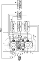
- Figure 2 is an explanatory drawing illustrating the configuration of the rolling mill according to the present embodiment and an apparatus for controlling the rolling mill. Note that, it is assumed that the rolling mill illustrated in Figure 2 is shown in a state as seen from the work side in the axial direction of rolls. Further, in Figure 2 , a configuration in a case when a lower backup roll is taken as the reference roll is illustrated. Note that, the reference roll is preferably a roll in which the area of contact between the chocks and the housing is large, and which is located at the lowermost part or the uppermost part at which the position is stable.
- the rolling mill illustrated in Figure 2 is a four-high rolling mill having a pair of work rolls 1, 2 and a pair of backup rolls 3, 4 that support the pair of work rolls 1, 2.
- the upper work roll 1 is supported by an upper work roll chock 5, and the lower work roll 2 is supported by a lower work roll chock 6.
- the upper work roll chock 5 and the lower work roll chock 6 are similarly provided on the side facing away from the viewer (drive side) in Figure 2 , and support the upper work roll 1 and the lower work roll 2, respectively.
- the upper work roll 1 and the lower work roll 2 are rotationally driven by a driving electric motor 21.
- the upper backup roll 3 is supported by an upper backup roll chock 7, and the lower backup roll 4 is supported by a lower backup roll chock 8.
- the upper backup roll chock 7 and the lower backup roll chock 8 are also similarly provided on the side facing away from the viewer (drive side) in Figure 2 , and support the upper backup roll 3 and the lower backup roll 4, respectively.
- the upper work roll chocks 5, the lower work roll chocks 6, the upper backup roll chocks 7 and the lower backup roll chocks 8 are retained by a housing 30
- the upper work roll chocks 5 are provided with an upper-work-roll-chock pressing apparatus 9 which is provided on the rolling-direction entrance side and which presses the upper work roll chocks 5 in the rolling direction, and a driving apparatus with upper work roll chock position detection function 11 which is provided on the rolling-direction exit side and which detects the position in the rolling direction and drives the upper work roll chocks 5 in the rolling direction. Further, an upper work roll thrust counterforce measurement apparatus 17 which measures a thrust counterforce that is applied to the upper work roll 1 is provided in the upper work roll 1.
- the lower work roll chocks 6 are provided with a lower-work-roll-chock pressing apparatus 10 which is provided on the rolling-direction entrance side and which presses the lower work roll chock 6 in the rolling direction, and a driving apparatus with lower work roll chock position detection function 12 which is provided on the rolling-direction exit side and which detects the position in the rolling direction and drives the lower work roll chocks 6 in the rolling direction.
- a lower work roll thrust counterforce measurement apparatus 18 which measures a thrust counterforce that is applied to the lower work roll 2 is provided in the lower work roll 2.
- a hydraulic cylinder is used as the driving apparatus with upper work roll chock position detection function 11, the driving apparatus with lower work roll chock position detection function 12, a drive mechanism of the upper-work-roll-chock pressing apparatus 9 and a drive mechanism of the lower-work-roll-chock pressing apparatus 10.
- the driving apparatus with upper work roll chock position detection function 11, the driving apparatus with lower work roll chock position detection function 12, and the upper and lower work-roll-chock pressing apparatuses 9 and 10 are shown only on the work side in Figure 2 , these apparatuses are also similarly provided on the side facing away from the viewer (drive side).
- the upper backup roll chocks 7 are provided with an upper-backup-roll-chock pressing apparatus 13 which is provided on the rolling-direction exit side and which presses the upper backup roll chock 7 in the rolling direction, and a driving apparatus with upper backup roll chock position detection function 14 which is provided on the rolling-direction entrance side and which detects the position in the rolling direction and drives the upper backup roll chock 7 in the rolling direction.
- a hydraulic cylinder is used as the driving apparatus with upper backup roll chock position detection function 14, and the drive mechanism of the upper-backup-roll-chock pressing apparatus 13.
- an upper backup roll thrust counterforce measurement apparatus 19 which measures a thrust counterforce that is applied to the upper backup roll 3 is provided in the upper backup roll 3.
- the driving apparatus with upper backup roll chock position detection function 14 and the upper-backup-roll-chock pressing apparatus 13 are shown only on the work side in Figure 2 , these apparatuses are also similarly provided on the side facing away from the viewer (drive side).
- the lower backup roll chocks 8 serve as reference roll chocks. Accordingly, since the lower backup roll chocks 8 are not driven to perform position adjustment, the lower backup roll chocks 8 do not necessarily need to have a driving apparatus and a position detecting apparatus as in the case of the upper backup roll chocks 7. However, as illustrated in Figure 2 , for example, a lower-backup-roll-chock pressing apparatus 40 or the like may be provided on the entrance side or the exit side in the rolling direction.
- a lower backup roll thrust counterforce measurement apparatus 20 which measures a thrust counterforce that is applied to the lower backup roll 4 is provided in the lower backup roll 4. Note that although the lower-backup-roll-chock pressing apparatus 40 is shown only on the work side in Figure 2 , this apparatus is also similarly provided on the side facing away from the viewer (drive side).
- the configuration includes a roll chock rolling direction force control unit 15, a roll chock position control unit 16, a driving electric motor control unit 22 and an inter-roll crossing control unit 23.
- the roll chock rolling direction force control unit 15 controls a pressing force in the rolling direction of the upper-work-roll-chock pressing apparatus 9, the lower-work-roll-chock pressing apparatus 10, the upper-backup-roll-chock pressing apparatus 13 and the lower-backup-roll-chock pressing apparatus 40. Based on a control instruction of the inter-roll crossing control unit 23 that is described later, the roll chock rolling direction force control unit 15 drives the upper-work-roll-chock pressing apparatus 9, the lower-work-roll-chock pressing apparatus 10 and the upper-backup-roll-chock pressing apparatus 13 that are control objects with respect to chock positions. By driving these roll chock pressing apparatuses to apply a predetermined pressing force to each roll chock, a state is entered in which it is possible to control the chock positions.
- the roll chock position control unit 16 performs drive control of the driving apparatus with upper work roll chock position detection function 11, the driving apparatus with lower work roll chock position detection function 12 and the driving apparatus with upper backup roll chock position detection function 14. Based on a control instruction of the inter-roll crossing control unit 23, the roll chock position control unit 16 drives the driving apparatus with upper work roll chock position detection function 11, the driving apparatus with lower work roll chock position detection function 12 and the driving apparatus with upper backup roll chock position detection function 14 so that thrust counterforces between rolls fall within a predetermined range.
- the driving apparatuses with position detection functions 11, 12 and 14 are disposed on both the work side and the drive side.
- the driving electric motor control unit 22 controls the driving electric motor 21 that rotationally drives the upper work roll 1 and the lower work roll 2.
- the driving electric motor control unit 22 controls driving of the upper work roll 1 or the lower work roll 2 based on an instruction from the inter-roll crossing control unit 23.
- the inter-roll crossing control unit 23 controls the position of each of the upper work roll 1, the lower work roll 2, the upper backup roll 3 and the lower backup roll 4 constituting the rolling mill, so that an inter-roll cross angle is zero. Based on thrust counterforces measured by the upper work roll thrust counterforce measurement apparatus 17, the lower work roll thrust counterforce measurement apparatus 18, the upper backup roll thrust counterforce measurement apparatus 19 and the lower backup roll thrust counterforce measurement apparatus 20, the inter-roll crossing control unit 23 issues control instructions to the roll chock rolling direction force control unit 15, the roll chock position control unit 16 and the driving electric motor control unit 22 so that the thrust counterforces are not more than an allowable range. By this means, it is attempted to eliminate crossing that has occurred between rolls. Note that the details of the method for setting the rolling mill are described later.
- the arrangement of these apparatuses with respect to the entrance side and the exit side of the rolling mill may be the reverse of the arrangement in the above example, or the pressing apparatuses 9, 10, 13 and the driving apparatuses with position detection functions 11, 12 and 14 may be installed on the same side with respect to the work rolls 1, 2 and the backup rolls 3, 4.
- the present invention is not limited to this example.
- These apparatuses may be provided on only one side among the work side and the drive side, or a configuration may be adopted so that only the apparatuses provided one side are actuated.
- it is possible to control an inter-roll cross angle by performing position control by taking the opposite side to the side on which the apparatuses are provided or to the side on which the apparatuses are actuated as the support point of rotation, and it is needless to say that the same effect of reducing inter-roll crossing is obtained.
- the present invention is not limited to this example.
- the upper and lower work roll thrust counterforce measurement apparatuses 17 and 18 and also the upper backup roll thrust counterforce measurement apparatus 19 or the lower backup roll thrust counterforce measurement apparatus 20 are provided with a roll thrust counterforce measurement apparatus, it is possible to execute the method for setting a rolling mill, described later, in a similar manner. The procedures for executing the method in such a case are described later.
- the present invention is not limited to this example.
- all of the rolls may be provided with a driving apparatus with a position detection function, and the reference roll may be changed according to the situation.
- the method for setting a rolling mill that is described later may be executed based on the changed reference roll.
- any one roll among the respective rolls that are arranged in the vertical direction is taken as a reference roll, and firstly at least a thrust counterforce in the axial direction of rolls that acts on a roll other than a backup roll is measured.
- the rolling direction position of the roll chocks of the reference roll is fixed as a reference position, and the roll chocks of the rolls other than the reference roll are moved in the rolling direction of the workpiece to adjust the positions of the roll chocks so that the measured thrust counterforce falls within an allowable range.
- the method for setting a rolling mill according to the present embodiment is a method that adjusts the relative positions of rolls by adjusting the positions of roll chocks so that inter-roll cross angles occurring between rolls that are built into a rolling mill become zero so that inter-roll thrust forces are not generated when the rolling mill is operated.
- This setting of the rolling mill is executed, for example, prior to zero adjustment of reduction positions at a time of roll replacement.
- the method for setting a rolling mill according to the present embodiment is different from a method that controls a rolling mill in order to suppress zigzagging or camber by taking into consideration inter-roll thrust forces which are generated when a rolling mill is operating.
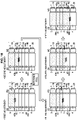
- Figure 3A and Figure 3B are flowcharts that describe the method for setting a rolling mill according to the present embodiment, which illustrate an example of a case where roll positions are adjusted from a roll on the opposite side to the reference roll.
- Figure 4 is an explanatory drawing illustrating procedures for performing roll position adjustment in the method for setting a rolling mill according to the present embodiment. Note that, in Figure 4 , a description of the distribution of a load that acts between rolls is omitted, and only a case in which, with respect to a thrust force and a thrust counterforce, only an inter-roll thrust force that is the target appears as a measurement value of the thrust counterforce.
- the lower backup roll 4 is described as the reference roll, in some cases the upper backup roll 3 is the reference roll. Note that, it suffices to set any one roll constituting the rolling mill as the reference roll, and it is preferable to adopt a roll that is at the uppermost part or the lowermost part in the vertical direction as the reference roll.
- the upper backup roll 3 is taken as the reference roll
- the inter-roll crossing control unit 23 causes a pressing-down device 27 to adjust roll positions in the vertical direction so that the upper work roll 1 and the lower work roll 2 enter a predetermined kiss roll state (S100a).
- the pressing-down device 27 applies a predetermined load to the rolls based on the instruction to thereby place the work rolls 1, 2 in a kiss roll state.
- position adjustment of the respective rolls is performed in a stepwise manner.
- the rolling direction position of the roll chocks of the reference roll is fixed as a reference position, and adjustment of the positions in the rolling direction of the roll chocks of the rolls other than the reference roll is performed by moving the roll chocks, to thereby adjust the relative positions of the rolls.
- the inter-roll crossing control unit 23 drives the driving electric motor 21 by means of the driving electric motor control unit 22 to cause the respective rolls to rotate.
- a thrust counterforce that acts on the upper backup roll 3 is measured by the upper backup roll thrust counterforce measurement apparatus 19 (S102a).
- the thrust counterforce acting on the upper backup roll 3 which was measured by the upper backup roll thrust counterforce measurement apparatus 19 is output to the inter-roll crossing control unit 23.
- the inter-roll crossing control unit 23 controls the position of the upper backup roll chocks 7 so that the measured thrust counterforce acting on the upper backup roll 3 falls within an allowable range (S104a).
- the upper and lower limit values with respect to the value of the thrust counterforce within an allowable range may be determined after performing roll deformation analysis under kiss roll conditions, and converting an asymmetric deformation amount into a reduction leveling amount. For example, it suffices to calculate upper and lower limit values within an allowable range of an inter-roll cross angle based on an existing rolling model in which a limit value of camber that is required for a product or a limit value of camber at which tail crash occurs is taken as a reference.
- the allowable range may be determined based on values at which the relevant thrust counterforce is maximum or minimum based on relative changes between the roll chock positions or inter-roll cross angle and the thrust counterforce.
- the inter-roll crossing control unit 23 instructs the roll chock rolling direction force control unit 15 and the roll chock position control unit 16 so as to adjust the position of the upper backup roll chocks 7. While detecting the position of the upper backup roll chocks 7 by means of the roll chock position control unit 16, the roll chock rolling direction force control unit 15 adjusts the position of the upper backup roll chocks 7 until the thrust counterforce acting on the upper backup roll 3 falls within the allowable range (S106a).
- step S106a when it is determined that the thrust counterforce acting on the upper backup roll 3 is within the allowable range, position adjustment of the upper backup roll chocks 7 ends.
- the inter-roll cross angle between the upper backup roll 3 and the upper work roll 1 is adjusted to within an allowable range.
- the rolling mill is adjusted so that an upper work roll thrust counterforce that acts on the upper work roll 1 that is in the roll assembly on the opposite side to the lower backup roll 4 that is the reference roll becomes zero.
- the inter-roll crossing control unit 23 measures a thrust counterforce that acts on the upper work roll 1 by means of the upper work roll thrust counterforce measurement apparatus 17 (S108a).
- the thrust counterforce acting on the upper work roll 1 that is measured by the upper work roll thrust counterforce measurement apparatus 17 is output to the inter-roll crossing control unit 23.
- the inter-roll crossing control unit 23 controls the position of the upper work roll chocks 5 so that the measured thrust counterforce acting on the upper work roll 1 falls within an allowable range (S110a).
- the inter-roll crossing control unit 23 instructs the roll chock rolling direction force control unit 15 and the roll chock position control unit 16 so as to adjust the position of the upper work roll chocks 5.
- the roll chock rolling direction force control unit 15 adjusts the position of the upper work roll chocks 5 until the thrust counterforce acting on the upper work roll 1 falls within the allowable range (S112a).
- the position of the upper backup roll chocks 7 is controlled so that the upper backup roll 3 for which inter-roll crossing with respect to the upper work roll 1 was already adjusted also moves simultaneously with and in the same direction as the upper work roll 1 while maintaining the relative positions between the roll chocks with respect to the upper work roll 1.
- adjustment of inter-roll crossing between the upper backup roll 3, the upper work roll 1 and the lower work roll 2 can be performed.
- step S112a when it is determined that the thrust counterforce acting on the upper work roll 1 is within the allowable range, position adjustment of the upper work roll chocks 5 ends.
- the positions of the respective rolls are adjusted by adjusting the positions of the roll chocks so that an inter-roll cross angle between the upper backup roll 3, the upper work roll 1 and the lower work roll 2 falls within an allowable range.
- the positions of the respective rolls are adjusted by adjusting the positions of the roll chocks so that a thrust counterforce that acts on the lower work roll 2 or the lower backup roll 4 that are in the roll assembly on the same side as the lower backup roll 4 that is the reference roll becomes zero.
- a thrust counterforce that acts on the lower work roll 2 or the lower backup roll 4 that are in the roll assembly on the same side as the lower backup roll 4 that is the reference roll becomes zero.
- the lower work roll thrust counterforce measurement apparatus 18 measures the thrust counterforce acting on the lower work roll 2, in a state in which each roll is being rotated by the driving electric motor 21.
- the thrust counterforce acting on the lower backup roll 4 is measured by the lower backup roll thrust counterforce measurement apparatus 20 (S114a).
- the thrust counterforce acting on the lower work roll 2 which was measured by the lower work roll thrust counterforce measurement apparatus 18, or the thrust counterforce acting on the lower backup roll 4 which was measured by the lower backup roll thrust counterforce measurement apparatus 20 is output to the inter-roll crossing control unit 23.
- the inter-roll crossing control unit 23 controls the position of the lower work roll chocks 6 so that the measured thrust counterforce falls within an allowable range (S116a).
- the inter-roll crossing control unit 23 instructs the roll chock rolling direction force control unit 15 and the roll chock position control unit 16 so as to adjust the position of the lower work roll chocks 6.
- the roll chock rolling direction force control unit 15 adjusts the position of the lower work roll chocks 6 until the thrust counterforce measured in step S114a falls within the allowable range (S118a).
- the positions of the upper work roll chocks 5 and the upper backup roll chocks 7 are controlled so that the upper work roll 1 and the upper backup roll 3 for which inter-roll crossing with respect to the lower work roll 2 was already adjusted also move simultaneously with and in the same direction as the lower work roll 2 while maintaining the relative positions between the roll chocks.
- adjustment of inter-roll crossing between the upper backup roll 3, the upper work roll 1, the lower work roll 2 and the lower backup roll 4 can be performed.
- step S118a when it is determined that the thrust counterforce acting on the lower work roll 2 is within the allowable range, position adjustment of the lower work roll chocks 6 ends.
- roll chock positions are adjusted so that inter-roll cross angles between the upper backup roll 3, the upper work roll 1, the lower work roll 2 and the lower backup roll 4 fall within an allowable range.
- the inter-roll crossing control unit 23 causes the pressing-down device 27 to adjust the roll gap between the upper work roll 1 and the lower work roll 2 so that the roll gap becomes a predetermined size (S120a). Thereafter, rolling of a workpiece by the rolling mill is started.
- Figure 5A and Figure 5B are flowcharts that describe the method for setting a rolling mill according to the present embodiment, which illustrate an example of a case where roll positions are adjusted from a roll on the reference roll side.
- Figure 6 is an explanatory drawing illustrating procedures for performing roll position adjustment in the method for setting a rolling mill according to the present embodiment.
- the upper backup roll 3 is the reference roll. Note that, it suffices to set any one roll constituting the rolling mill as the reference roll, and it is preferable to adopt a roll that is at the uppermost part or the lowermost part in the vertical direction as the reference roll. In this case also, it suffices to perform position adjustment of the respective rolls by similar procedures as described hereunder.
- the inter-roll crossing control unit 23 causes the pressing-down device 27 to adjust roll positions in the vertical direction so that the upper work roll 1 and the lower work roll 2 enter a predetermined kiss roll state (S100b).
- the pressing-down device 27 applies a predetermined load to the rolls based on the instruction to thereby place the work rolls 1, 2 in a kiss roll state.
- position adjustment of the respective rolls is performed in a stepwise manner.
- the rolling direction position of the roll chocks of the reference roll is fixed as a reference position, and adjustment of the positions in the rolling direction of the roll chocks of the rolls other than the reference roll is performed by moving the roll chocks, to thereby adjust the relative positions of the rolls.
- the inter-roll crossing control unit 23 drives the driving electric motor 21 by means of the driving electric motor control unit 22 to cause the respective rolls to rotate.
- a thrust counterforce that acts on the lower backup roll 4 is measured by the lower backup roll thrust counterforce measurement apparatus 20 (S102b).
- the thrust counterforce acting on the lower backup roll 4 which was measured by the lower backup roll thrust counterforce measurement apparatus 20 is output to the inter-roll crossing control unit 23.
- the inter-roll crossing control unit 23 controls the position of the lower work roll chocks 6 so that the measured thrust counterforce acting on the lower backup roll 4 falls within an allowable range (S104b).
- the inter-roll crossing control unit 23 instructs the roll chock rolling direction force control unit 15 and the roll chock position control unit 16 so as to adjust the position of the lower work roll chocks 6.
- the roll chock rolling direction force control unit 15 adjusts the position of the lower work roll chocks 6 until the thrust counterforce acting on the lower backup roll 4 falls within the allowable range (S106b).
- the positions of the upper work roll chocks 5 and the upper backup roll chocks 7 are controlled so that the upper work roll 1 and the upper backup roll 3 also move simultaneously with and in the same direction as the lower work roll 2 while maintaining the relative positions between the roll chocks.
- adjustment of inter-roll crossing between the lower work roll 2 and the lower backup roll 4 can be performed while the state of inter-roll crossing between the upper backup roll 3 and the upper work roll 1 and the lower work roll 2 is maintained.
- step S106b when it is determined that the thrust counterforce acting on the lower backup roll 4 is within the allowable range, position adjustment of the lower work roll chocks 6 ends.
- the inter-roll cross angle between the lower backup roll 4 and the lower work roll 2 is adjusted to within an allowable range.
- the rolling mill is adjusted so that a lower work roll thrust counterforce that acts on the lower work roll 2 that is in the roll assembly on the side of the lower backup roll 4 that is the reference roll becomes zero.
- the inter-roll crossing control unit 23 measures a thrust counterforce that acts on the lower work roll 2 by means of the lower work roll thrust counterforce measurement apparatus 18 (S108b).
- the thrust counterforce acting on the lower work roll 2 measured by the lower work roll thrust counterforce measurement apparatus 18 is output to the inter-roll crossing control unit 23.
- the inter-roll crossing control unit 23 controls the position of the upper work roll chocks 5 so that the measured thrust counterforce acting on the lower work roll 2 falls within an allowable range (S110b).
- the inter-roll crossing control unit 23 instructs the roll chock rolling direction force control unit 15 and the roll chock position control unit 16 so as to adjust the position of the upper work roll chocks 5.
- the roll chock rolling direction force control unit 15 adjusts the position of the upper work roll chocks 5 until the thrust counterforce acting on the upper work roll 1 falls within the allowable range (S112b).
- the position of the upper backup roll chocks 7 is controlled so that the upper backup roll 3 also moves simultaneously with and in the same direction as the upper work roll 1 while maintaining the relative positions between the roll chocks.
- adjustment of inter-roll crossing between the upper work roll 1 and the lower work roll 2 and the lower backup roll 4 can be performed while maintaining the state of inter-roll crossing between the upper backup roll 3 and the upper work roll 1.
- step S112b when it is determined that the thrust counterforce acting on the upper work roll 1 is within the allowable range, position adjustment of the upper work roll chocks 5 ends.
- the positions of the respective rolls are adjusted by adjusting the positions of the roll chocks so that an inter-roll cross angle between the upper work roll 1, the lower work roll 2 and the lower backup roll 4 falls within an allowable range.
- the positions of the respective rolls are adjusted by adjusting the positions of the roll chocks so that a thrust counterforce that acts on the upper work roll 1 that is in the roll assembly on the opposite side to the lower backup roll 4 that is the reference roll becomes zero.
- the upper work roll thrust counterforce measurement apparatus 17 measures the thrust counterforce acting on the upper work roll 1, in a state in which each roll is being rotated by the driving electric motor 21 (S114b).
- the thrust counterforce acting on the upper work roll 1 which was measured by the upper work roll thrust counterforce measurement apparatus 17 is output to the inter-roll crossing control unit 23.
- the inter-roll crossing control unit 23 controls the position of the upper backup roll chocks 7 so that the measured thrust counterforce falls within an allowable range (S116b).
- the inter-roll crossing control unit 23 instructs the roll chock rolling direction force control unit 15 and the roll chock position control unit 16 so as to adjust the position of the upper backup roll chocks 7.
- the roll chock rolling direction force control unit 15 adjusts the position of the upper backup roll chocks 7 until the thrust counterforce measured in step S114b falls within the allowable range (S118b).
- adjustment of inter-roll crossing between the upper backup roll 3, the upper work roll 1, the lower work roll 2 and the lower backup roll 4 can be performed.
- step S118b when it is determined that the thrust counterforce acting on the upper work roll 1 is within the allowable range, position adjustment of the upper backup roll chocks 7 ends.
- roll chock positions are adjusted so that inter-roll cross angles between the upper backup roll 3, the upper work roll 1, the lower work roll 2 and the lower backup roll 4 fall within an allowable range.
- the inter-roll crossing control unit 23 causes the pressing-down device 27 to adjust the roll gap between the upper work roll 1 and the lower work roll 2 so that the roll gap becomes a predetermined size (S120b). Thereafter, rolling of a workpiece by the rolling mill is started.
- a rolling apparatus and a method for setting a rolling mill according to the first embodiment of the present invention have been described above. Note that, although in the configuration described above a measurement apparatus for measuring a thrust counterforce is provided for rolls other than the backup roll on the opposite side to the reference roll, needless to say that the present invention can be similarly applied in a case where a measurement apparatus for measuring a thrust counterforce is provided for all of the rolls. Further, in a case where a thrust counterforce measurement apparatus is only provided for the work rolls also, it suffices to perform adjustment of inter-roll crossing in an exploratory manner based on values at which relative changes in a thrust counterforce with respect to the position of the roll chock position control unit becomes a maximum or a minimum.
- a rolling mill according to a second embodiment of the present invention the configuration of an apparatus for controlling the rolling mill, and a method for setting a rolling mill will be described based on Figure 7 to Figure 9 .
- the method for setting a rolling mill according to the second embodiment first, with respect to an upper roll assembly that is composed of the upper work roll 1 and the upper backup roll 3, and a lower roll assembly that is composed of the lower work roll 2 and the lower backup roll 4, operations are performed to make thrust counterforces between the upper work roll 1 and the upper backup roll 3 and between the lower work roll 2 and the lower backup roll 4 zero, respectively.
- the upper work roll 1 and the lower work roll 2 are set in a kiss roll state, and operations are performed to make a thrust counterforce between the upper work roll 1 and the lower work roll 2 zero.
- adjustment is performed to make the inter-roll cross angles for all the rolls constituting the rolling mill zero, and rolling in which a thrust force does not arise is realized.
- Figure 7 is an explanatory drawing illustrating the configuration of the rolling mill according to the present embodiment, and the configuration of an apparatus for controlling the rolling mill.
- the rolling mill illustrated in Figure 7 is shown in a state as seen from the work side in the axial direction of rolls, and in Figure 7 a configuration in a case where the lower backup roll is taken as the reference roll is illustrated.
- the rolling mill according to the present embodiment illustrated in Figure 7 is a four-high rolling mill having a pair of work rolls 1, 2 and a pair of backup rolls 3, 4 which support the pair of work rolls 1, 2.
- the configuration of the rolling mill according to the present embodiment differs from the configuration of the rolling mill of the first embodiment illustrated in Figure 2 in that the upper backup roll thrust counterforce measurement apparatus 19 and the lower backup roll thrust counterforce measurement apparatus 20 are not provided in the rolling mill of the present embodiment, and that the rolling mill of the present embodiment includes increase bending apparatuses 24a, 24b, 25a, 25b and an increase bending control unit 26 that controls the increase bending apparatuses 24a, 24b, 25a, 25b.
- the remaining configuration is the same as the configuration of the rolling mill of the first embodiment illustrated in Figure 2 , and therefore a description thereof is omitted in the present embodiment.
- the rolling mill includes an entrance-side upper increase bending apparatus 24a and an exit-side upper increase bending apparatus 24b on a project block between the upper work roll chocks 5 and the housing 30. Further, the rolling mill includes an entrance-side lower increase bending apparatus 25a and an exit-side lower increase bending apparatus 25b on a project block between the lower work roll chocks 6 and the housing 30.
- the entrance-side upper increase bending apparatus 24a, the exit-side upper increase bending apparatus 24b, the entrance-side lower increase bending apparatus 25a and the exit-side lower increase bending apparatus 25b are also similarly provided on the side facing away from the viewer (drive side) in Figure 7 .
- Each increase bending apparatus imparts an increase bending force for applying a load to the upper work roll 1 and the upper backup roll 3, and the lower work roll 2 and the lower backup roll 4.
- the increase bending control unit 26 is an apparatus that controls the entrance-side upper increase bending apparatus 24a, the exit-side upper increase bending apparatus 24b, the entrance-side lower increase bending apparatus 25a and the exit-side lower increase bending apparatus 25b.
- the increase bending control unit 26 controls the increase bending apparatuses so as to impart an increase bending force to the work roll chocks, based on an instruction from the inter-roll crossing control unit 23. Note that, even in a case other than a case of performing adjustment of inter-roll crossing according to the present embodiment, for example, when performing crown control or shape control of a workpiece, the increase bending control unit 26 may perform control of the increase bending apparatuses.
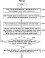
- Figure 8A and Figure 8B are flowcharts illustrating the method for setting a rolling mill according to the present embodiment.
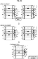
- Figure 9 is an explanatory drawing showing procedures for roll position adjustment in the method for setting a rolling mill illustrated in Figure 8A and Figure 8B . Note that, in Figure 9 , a description of the distribution of a load that acts between rolls is omitted, and only a case in which, with respect to a thrust force and a thrust counterforce, only an inter-roll thrust force that is the target appears as a measurement value of the thrust counterforce.
- a roll gap between the upper work roll 1 and the lower work roll 2 is made an open state. Then, with respect to the upper roll assembly and the lower roll assembly, operations are performed independently and respectively to adjust the positions of the work roll chocks that have an increase bending apparatus so that a thrust counterforce between the work roll and the backup roll becomes zero, and an inter-roll cross angle between these is made to fall within an allowable range.
- the upper work roll 1 and the lower work roll 2 are set in a kiss roll state. Thereafter, the positions of the roll chocks of either one of the roll assemblies are adjusted so that the thrust counterforce between the upper work roll 1 and the lower work roll 2 becomes zero.
- the inter-roll cross angle between the upper roll assembly and the lower roll assembly falls within an allowable range.
- the inter-roll cross angles of all the rolls constituting the rolling mill fall within an allowable range.
- the rolling direction position of the roll chocks of the reference roll is fixed as a reference position, and the positions in the rolling direction of roll chocks of rolls other than the reference roll are moved to thereby adjust the positions of the roll chocks.
- the inter-roll crossing control unit 23 causes the pressing-down device 27 to adjust the roll positions in the vertical direction so that the roll gap between the upper work roll 1 and the lower work roll 2 becomes an open state having a predetermined gap (S200). Based on the relevant instruction, the pressing-down device 27 places the increase bending forces in a balanced state, and places the roll gap between the work rolls 1, 2 in an open state.
- the term "balanced state” refers to a state in which a bending force of a degree that lifts up the self-weight of the work roll and roll chocks or the like is applied, and means that a load acting between the work roll and the backup roll is approximately zero.
- the inter-roll crossing control unit 23 instructs the increase bending control unit 26 so as to apply a predetermined increase bending force from the balanced state to the work roll chocks 5, 6 by means of the increase bending apparatuses 24a, 24b, 25a, 25b (S202).
- the increase bending control unit 26 controls the respective increase bending apparatuses 24a, 24b, 25a, 25b based on the instruction, to thereby apply a predetermined increase bending force to the work roll chocks 5, 6.
- the roll gap between the work rolls is placed in an open state. Note that, either step among the step S200 and step S202 may be executed first.
- the inter-roll crossing control unit 23 drives the driving electric motor 21 by means of the driving electric motor control unit 22 to cause the respective rolls to rotate (S204).
- the thrust counterforces acting on the upper and lower work rolls are measured by the thrust counterforce measurement apparatuses 17, 18 of the work rolls, and the measured values are output to the inter-roll crossing control unit 23.
- the inter-roll crossing control unit 23 then controls the positions of the roll chocks of the rolls that have a bending apparatus, that is, the work roll chocks 5, 6, so that the thrust counterforces acting on the upper and lower work rolls become values that are within an allowable range (first adjustment illustrated on the upper side in Figure 9 ; S206).
- position control of the upper backup roll chocks 7 may be performed. That is, as illustrated in the center in Figure 9 , the first adjustment may be performed by performing position control of the backup roll of the roll assembly on the opposite side to the reference roll, that is, position control of the upper backup roll chocks 7 so that a thrust counterforce that acts on the upper work roll of the upper roll assembly becomes a value that is within an allowable range.
- step S208 with respect to the upper roll assembly and the lower roll assembly, when it is determined that thrust counterforces acting on the work rolls or backup rolls are within an allowable range, position adjustment of the work roll chocks 5, 6 ends.
- first adjustment performed in this manner, inter-roll crossing between the upper backup roll 3 and the upper work roll 1, and an inter-roll cross angle between the lower backup roll 4 and the lower work roll 2 are each adjusted to within an allowable range.
- the inter-roll crossing control unit 23 adjusts inter-roll crossing between the upper roll assembly and the lower roll assembly, as illustrated on the lower side in Figure 9 .
- the inter-roll crossing control unit 23 causes the pressing-down device 27 to adjust roll positions in the vertical direction so that the upper work roll 1 and the lower work roll 2 enter a predetermined kiss roll state (S210).
- the pressing-down device 27 applies a predetermined load to the rolls based on the instruction to thereby cause the work rolls 1, 2 to come in contact and enter a kiss roll state.
- the inter-roll crossing control unit 23 causes the driving electric motor 21 to drive by means of the driving electric motor control unit 22 to cause each roll to rotate.
- thrust counterforces acting on the upper work roll 1 and the lower work roll 2 are measured by the upper work roll thrust counterforce measurement apparatus 17 and the lower work roll thrust counterforce measurement apparatus 18 (S212).
- the values of the thrust counterforces acting on the upper work roll 1 and the lower work roll 2 that were measured by the upper work roll thrust counterforce measurement apparatus 17 and the lower work roll thrust counterforce measurement apparatus 18 are output to the inter-roll crossing control unit 23.
- the inter-roll crossing control unit 23 controls the positions of the work roll chocks and the backup roll chocks of the upper roll assembly or the lower roll assembly simultaneously and in the same direction while maintaining the relative position between the roll chocks, so that thrust counterforces acting on the upper work roll 1 and the lower work roll 2 become a value within an allowable range (S214).
- the positions of the upper work roll chocks 5 and the upper backup roll chocks 7 of the upper roll assembly are controlled so that an inter-roll cross angle with respect to the lower roll assembly falls within an allowable range.
- the inter-roll crossing control unit 23 instructs the roll chock rolling direction force control unit 15 and the roll chock position control unit 16 so as to adjust the positions of the work roll chocks and the backup roll chocks on the opposite side to the reference roll assembly.
- the roll chock rolling direction force control unit 15 adjusts the positions of the work roll chocks and the backup roll chocks until thrust counterforces acting on the upper work roll 1 and the lower work roll 2 fall within the allowable range (S216).
- the roll chock rolling direction force control unit 15 adjusts the positions of the work roll chocks and the backup roll chocks until thrust counterforces acting on the upper work roll 1 and the lower work roll 2 fall within the allowable range (S216).
- the allowable range S216
- step S216 when it is determined that the thrust counterforces acting on the upper work roll 1 and the lower work roll 2 have entered the allowable range, the roll chock positions are adjusted so that an inter-roll cross angle between the upper backup roll 3, the upper work roll 1, the lower work roll 2 and the lower backup roll 4 falls within an allowable range.
- the inter-roll crossing control unit 23 causes the pressing-down device 27 to perform adjustment so that the roll gap between the upper work roll 1 and the lower work roll 2 becomes a predetermined size (S218). Thereafter, rolling of a workpiece by the rolling mill is started.
- a rolling apparatus and a method for setting a rolling mill according to the second embodiment of the present invention have been described above.
- a backup roll thrust counterforce measurement apparatus is provided in the upper or lower backup roll or in both of the upper and lower backup rolls, it need scarcely be said that control can be similarly performed.
- position control of roll chocks is performed so that a thrust counterforce generated between rolls becomes zero or becomes a value that is within an allowable range in order to eliminate inter-roll crossing. This is based on the finding that the correlation described hereunder exists between a thrust counterforce and an inter-roll cross angle.
- the relation between an inter-roll cross angle and various values will be described based on Figure 10 to Figure 16 .
- Figure 10 is an explanatory drawing illustrating the arrangement of the work rolls 1, 2 and the backup rolls 3, 4 of a rolling mill in which the roll gap is in an open state.
- Figure 11 is an explanatory drawing showing the definition of an inter-roll cross angle.
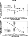
- Figure 12 is a multiple view drawing showing graphs that illustrate a relation between a backup roll cross angle and upper and lower backup roll thrust counterforces and between a backup roll cross angle and upper and lower work roll thrust counterforces when a roll gap is in an open state, which are relations obtained as the results of an experiment performed using a small size rolling mill with a work roll diameter of 80 mm. Note that, in Figure 12 , values are shown that were obtained by measuring upper and lower backup roll thrust counterforces and upper and lower work roll thrust counterforces in both a case where a backup roll cross angle was set in an increasing direction and a case where a backup roll cross angle was set in a decreasing direction, respectively, and averaging the measurement value for the increasing direction and the measurement value for the decreasing direction.
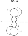
- Figure 13 is an explanatory drawing illustrating the arrangement of the work rolls 1, 2 and the backup rolls 3, 4 of the rolling mill that has been set in a kiss roll state.
- Figure 14 is a multiple view drawing showing graphs that illustrate a relation between a backup roll cross angle and upper and lower backup roll thrust counterforces and between a backup roll cross angle and upper and lower work roll thrust counterforces in a kiss roll state.
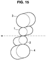
- Figure 15 is an explanatory drawing illustrating the arrangement of the work rolls 1, 2 and the backup rolls 3, 4 of the rolling mill that has been set in a kiss roll state.
- Figure 16 is a multiple view drawing showing graphs that illustrate a relation between a pair cross angle between a work roll and a backup roll and upper and lower backup roll thrust counterforces, and between a pair cross angle between a work roll and a backup roll and upper and lower work roll thrust counterforces in a kiss roll state.
- thrust counterforces of each roll are measured before zero point of reduction position adjustment or before the start of rolling, and the roll chock positions of the respective rolls are controlled based on a reference roll so that the thrust counterforces enter an allowable range based on appropriate logic.
- the upper and lower work rolls were set in a kiss roll state, thrust counterforces acting on the upper and lower work rolls were measured, and the positions of the roll chocks of the upper and lower work rolls and the backup rolls were controlled so that the thrust counterforces in question entered an allowable range that was set in advance.
- Table 1 shows actual measurement values for the occurrence of camber with regard to a representative number of rolled workpieces, with respect to the present invention and the conventional method.
- Table 1 shows actual measurement values for camber per 1 m of a front end position of the workpieces, when the value for immediately before backup roll replacement and immediately before housing liner replacement are seen, it is found that in the case of the present invention the value is kept to a relatively small value of 0.11 mm/m.
- the actual measurement value for camber is large in comparison to the case of the present invention.
- thrust counterforces of work rolls are measured before zero point of reduction position adjustment or before the start of rolling, and the chock positions of the respective rolls are controlled based on a reference roll so that the thrust counterforces enter an allowable range based on appropriate logic.
- a driving apparatus with a roll chock position detection function that detects the position in the rolling direction of work roll chocks
- the present invention is not limited to this example.
- positions in the rolling direction of work roll chocks can be measured. That is, as shown in the example of the upper work roll 1 and the upper work roll chocks 5 illustrated in Figure 17 , a servo-motor with a rotation angle detection function 34 may be provided so as to face the driving apparatus with upper work roll chock position detection function 11 in the rolling direction of the upper work roll chocks 5.
- the present invention is also applicable to a rolling mill having more rolls than a four-high rolling mill.
- any roll among the work rolls, intermediate rolls and backup roll can be set as the reference roll.
- intermediate rolls 41, 42 are provided between the work roll 1 and the backup roll 3, and the work roll 2 and the backup roll 4, respectively.
- the upper intermediate roll 41 is supported by an upper intermediate roll chock 43a on the work side and an upper intermediate roll chock 43b on the drive side (the upper intermediate roll chocks 43a, 43b are also referred to together as "upper intermediate roll chocks 43").
- the lower intermediate roll 42 is supported by a lower intermediate roll chock 44a on the work side and a lower intermediate roll chocks 44b on the drive side (the lower intermediate roll chocks 44a, 44b are also referred to together as "lower intermediate roll chocks 44").
- the upper work roll thrust counterforce measurement apparatus 17 that measures thrust counterforces applied to the upper work roll 1
- the lower work roll thrust counterforce measurement apparatus 18 that measures thrust counterforces applied to the lower work roll 2
- the upper backup roll thrust counterforce measurement apparatus 19 that measures thrust counterforces applied to the upper backup roll 3
- the lower backup roll thrust counterforce measurement apparatus 20 that measures thrust counterforces applied to the lower backup roll 4 is provided.
- an upper intermediate roll thrust counterforce measurement apparatus 45 that measures thrust counterforces applied to the upper intermediate roll 41 is provided, and in the lower intermediate roll 42 a lower intermediate roll thrust counterforce measurement apparatus 46 that measures thrust counterforces applied to the lower intermediate roll 42 is provided.
- the adjustment is performed in sequence as follows: a first adjustment is performed that performs a roll chock adjustment between the upper backup roll chocks 7 of the upper backup roll 3 and the upper intermediate roll chocks 43 of the upper intermediate roll 41; a second adjustment is performed that performs a roll chock adjustment between the upper intermediate roll chocks 43 of the upper intermediate roll 41 and the upper work roll chocks 5 of the upper work roll 1; a third adjustment is performed that performs a roll chock adjustment between the upper work roll chocks 5 of the upper work roll 1 and the lower work roll chocks 6 of the lower work roll 2; a fourth adjustment is performed that performs a roll chock adjustment between the lower work roll chocks 6 of the lower work roll 2 and the lower intermediate roll chocks 44 of the lower intermediate roll 42; and a fifth adjustment is performed that performs a roll chock adjustment between the lower intermediate roll chocks 44 of the lower intermediate roll 42 and the lower backup roll chocks 8 of the lower
- adjustment of roll chock positions may be performed in sequence from the roll chocks of the intermediate roll on the reference roll side in a manner so that a thrust counterforce generated at the adjacent roll falls within an allowable range.
- a roll thrust counterforce measurement apparatus is not provided in the backup roll (that is, the upper backup roll 3) on the opposite side from the reference roll.
- the upper work roll thrust counterforce measurement apparatus 17, the lower work roll thrust counterforce measurement apparatus 18, the lower backup roll thrust counterforce measurement apparatus 20, the upper intermediate roll thrust counterforce measurement apparatus 45, and the lower intermediate roll thrust counterforce measurement apparatus 46 are provided in the upper work roll 1, the lower work roll 2, the lower backup roll 4, the upper intermediate roll 41 and the lower intermediate roll 42, respectively.
- the adjustment is performed in sequence as follows: a first adjustment is performed that performs a roll chock adjustment between the lower backup roll chocks 8 of the lower backup roll 4 that is the reference roll and the lower intermediate roll chocks 44 of the lower intermediate roll 42; a second adjustment is performed that performs a roll chock adjustment between the lower intermediate roll chocks 44 of the lower intermediate roll 42 and the lower work roll chocks 6 of the lower work roll 2; a third adjustment is performed that performs a roll chock adjustment between the lower work roll chocks 6 of the lower work roll 2 and the upper work roll chocks 5 of the upper work roll 1; a fourth adjustment is performed that performs a roll chock adjustment between the upper work roll chocks 5 of the upper work roll 1 and the upper intermediate roll chocks 43 of the upper intermediate roll 41; and a fifth adjustment is performed that performs a roll chock adjustment between the upper intermediate roll chocks 43 of the upper intermediate roll 41 and the upper backup roll chocks 7 of
- a roll thrust counterforce measurement apparatus is not provided in the upper backup roll 3 and the lower backup roll 4, and similarly to Figure 18 , the upper work roll thrust counterforce measurement apparatus 17, the lower work roll thrust counterforce measurement apparatus 18, the upper intermediate roll thrust counterforce measurement apparatus 45, and the lower intermediate roll thrust counterforce measurement apparatus 46 are provided in the upper work roll 1, the lower work roll 2, the upper intermediate roll 41 and the lower intermediate roll 42, respectively.
- the roll gap between the work rolls 1, 2 is placed in an open state, and for the upper roll assembly and the lower roll assembly, respectively, a first adjustment is performed to adjust the positions between the roll chocks 43, 44 of the intermediate rolls 41, 42 and the roll chocks 7, 8 of the backup rolls 3, 4. Subsequently, after finishing the first adjustment, the roll gap between the work rolls 1, 2 is maintained in an open state, and for the upper roll assembly and the lower roll assembly, respectively, a second adjustment is performed to adjust the positions between the roll chocks 43, 44 of the intermediate rolls 41, 42 and the roll chocks 5, 6 of the work rolls 1, 2.
- the work rolls 1, 2 are set in a kiss roll state, and either one of the upper roll assembly and the lower roll assembly is taken as the reference roll assembly.
- the lower roll assembly is taken as the reference roll assembly.
- the roll chock positions of the reference roll assembly are fixed as reference positions, and a third adjustment is performed in which the positions of the roll chocks are adjusted between the upper roll assembly and the lower roll assembly by controlling the roll chocks 5, 43, 7 of the respective rolls 1, 41, 3 of the upper roll assembly simultaneously and in the same direction while maintaining the relative positions between the roll chocks 5, 43, 7.
- bending apparatuses of the intermediate rolls 41, 42 are used to apply loads between the intermediate rolls 41, 42 and the backup rolls 3, 4, and the bending apparatuses of the work rolls 1, 2 are set at zero or in a balanced state.
- bending apparatuses of the work rolls 1, 2 are used to apply loads between the work rolls 1, 2 and the intermediate rolls 41, 42, and the bending apparatuses of the intermediate rolls 41, 42 are set at zero or in a balanced state.
- the decrease bending apparatuses may be case to act in a direction (minus direction) such that the respective loads between the intermediate rolls 41, 42 and the backup rolls 3, 4 are decreased.
- the present invention is also applicable to a six-high rolling mill, and not just a four-high rolling mill. Furthermore, the present invention is similarly applicable to rolling mills other than a four-high rolling mill and a six-high rolling mill, and for example the present invention can also be applied to an eight-high rolling mill or a five-high rolling mill.
- Figure 21 is a block diagram illustrating an example of the hardware configuration of an information processing apparatus 100 that functions as an apparatus for controlling the rolling mills according to the respective embodiments of the present invention.
- the information processing apparatus 100 includes a CPU 901, a ROM 903 and a RAM 905 as main components.
- the information processing apparatus 100 also includes a bus 907, an input device 909, an output device 911, a storage device 913, a drive 915, a connection port 917 and a communication device 919.
- the CPU 901 functions as an arithmetic processing unit and a control unit, and controls all or some of the operations inside the information processing apparatus 100 in accordance with various programs recorded on the ROM 903, the RAM 905, the storage device 913 or the removable recording medium 921.
- the ROM 903 stores programs or computation parameters or the like that the CPU 901 uses.
- the RAM 905 performs primary storage of programs that the CPU 901 uses as well as parameters that change as appropriate during execution of a program. These components are connected to each other by the bus 907 that is constituted by an internal bus such as a CPU bus.
- the bus 907 is connected to an external bus such as a PCI (Peripheral Component Interconnect/Interface) bus through a bridge.
- PCI Peripheral Component Interconnect/Interface
- the input device 909 is a device for inputting information, and has operation means that allows a user to operate the information processing apparatus 100.
- the input device 909 has an input control circuit that generates an input signal based on information that is inputted by the user using the operation means, and outputs the input signal to the CPU 901.
- the input device 909 has, for example, a mouse, a keyboard, a touch panel, buttons, switches and a lever as input means.
- the input device 909 may be, for example, a remote control that utilizes infrared rays or other electric waves, and may be an external connection device 923 such as a PDA (Personal Digital Assistant) that can operate the information processing apparatus 100.
- PDA Personal Digital Assistant
- the output device 911 is a device that is capable of information to the user visually or auditorily.
- the output device 911 is, for example, a display device such as a CRT display device, a liquid crystal display device, a plasma display device, an EL display device or a lamp, or a sound output device such as a speaker and a headphone, or is a printer device.
- the output device 911 outputs, for example, results acquired by various kinds of processing executed by the information processing apparatus 100.
- the output device 911 can display results acquired by various kinds of processing executed by the information processing apparatus 100, as text or images.
- the output device 911 can convert an audio signal including sound data and acoustic data into an analog signal and output the analog signal.
- the storage device 913 is a device for data storage constituted as an example of a storage unit of the information processing apparatus 100.
- the storage device 913 is, for example, a magnetic storage unit device such as an HDD (Hard Disk Drive), a semiconductor storage device, an optical storage device, or a magneto-optical storage device.
- the storage device 913 stores programs that are executed by the CPU 901 and various kinds of data, as well as various kinds of data acquired from outside.
- the drive 915 is a reader/writer for use as a recording medium, and is built into the information processing apparatus 100 or is attached to the information processing apparatus 100 from outside.
- the drive 915 reads out information recorded on the removable recording medium 921 such as an inserted magnetic disk, optical disk, magneto-optical disk or semiconductor memory, and outputs the information to the RAM 905.
- the drive 915 can also write information onto the removable recording medium 921 that is inserted.
- the removable recording medium 921 is, for example, a CD medium, a DVD medium, or a Blu-ray (registered trademark) medium.
- the removable recording medium 921 may also be a CompactFlash (CF) (registered trademark), a flash memory or an SD memory card (Secure Digital memory card) or the like.
- the removable recording medium 921 may also be, for example, an IC card (Integrated Circuit card) or an electronic device in which a non-contact IC chip is mounted.
- the connection port 917 is a port for directly connecting a device to the information processing apparatus 100.
- the connection port 917 is, for example, a USB (Universal Serial Bus) port, an IEEE1394 port, an SCSI (Small Computer System Interface) port, or an RS-232C port.
- the communication device 919 is a communication interface constituted by a communication device or the like for connecting to a communication network 925.
- the communication device 919 is, for example, a wired or wireless LAN (Local Area Network), Bluetooth (registered trademark), or a communication card for a WUSB (Wireless USB). Further, the communication device 919 may be a router for optical communication, a router for ADSL (Asymmetric Digital Subscriber Line), or a modem for various kinds of communication.
- the communication device 919 can, for example, transmit and receive signals and the like according to a predetermined protocol such as TCP/IP to and from the Internet or other communication devices.
- the communication network 925 that is connected to by the communication device 919 is a network that is connected to by wire or wirelessly, and may be, for example, the Internet, a LAN, infrared-ray communication, radio wave communication, or satellite communication.
Landscapes
- Engineering & Computer Science (AREA)
- Mechanical Engineering (AREA)
- Control Of Metal Rolling (AREA)
- Casting Or Compression Moulding Of Plastics Or The Like (AREA)
Claims (10)
- Procédé pour régler un laminoir,le laminoir étant un laminoir de hauteur quatre ou plus qui inclut plusieurs rouleaux incluant au moins une paire de rouleaux de travail (1, 2) et une paire de rouleaux d'appui (3, 4) qui supportent les rouleaux de travail (1, 2),le procédé caractérisé en ce que :
avant le point zéro d'ajustement de position de réduction ou avant le démarrage du laminage, un rouleau parmi les rouleaux respectifs disposés dans une direction verticale est considéré comme un rouleau de référence,le procédé comprend :une étape de mesure de contreforce de poussée mesurant des contreforces de poussée dans une direction axiale de rouleaux qui agissent sur au moins les rouleaux différents des rouleaux d'appui (3, 4) ; etune étape d'ajustement de position d'empoise fixant une position de direction de laminage d'une empoise (5, 6, 7, 8, 43, 44) du rouleau de référence comme une position de référence, et déplaçant les empoises (5, 6, 7, 8, 43, 44) des rouleaux différents du rouleau de référence dans une direction de laminage d'une pièce à usiner pour ajuster les positions des empoises (5, 6, 7, 8, 43, 44) de sorte que les contreforces de poussée mesurées se trouvent dans un intervalle permis. - Procédé de réglage d'un laminoir selon la revendication 1, dans lequel un rouleau disposé sur une partie inférieure ou une partie supérieure dans la direction verticale parmi les plusieurs rouleaux est considéré comme le rouleau de référence.
- Procédé de réglage d'un laminoir selon la revendication 2, dans lequel :dans l'étape d'ajustement de position d'empoise, les rouleaux de travail (1, 2) sont réglés dans un état de léchage, et dans un ordre à partir d'un rouleau sur un côté opposé au rouleau de référence, les empoises (5, 6, 7, 8, 43, 44) du rouleau qui est un objet d'ajustement de position sont déplacées dans la direction de laminage de la pièce à usiner pour ajuster la position des empoises (5, 6, 7, 8, 43, 44) de sorte qu'une contreforce de poussée produite entre les rouleaux qui sont adjacents se trouve dans un intervalle permis, età ce moment, les empoises (5, 6, 7, 8, 43, 44) des rouleaux pour lesquels la position des empoises (5, 6, 7, 8, 43, 44) est déjà ajustée sont contrôlées simultanément et dans une direction identique tout en maintenant une position relative par rapport aux empoises (5, 6, 7, 8, 43, 44) du rouleau qui est l'objet d'ajustement de position.
- Procédé pour le réglage d'un laminoir selon la revendication 2, dans lequel :dans l'étape d'ajustement de position d'empoise, les rouleaux de travail (1, 2) sont réglés dans un état de léchage, et dans un ordre du côté de rouleau de référence, les empoises (5, 6, 7, 8, 43, 44) du rouleau qui est un objet d'ajustement de position sont déplacées dans la direction de laminage de la pièce à usiner pour ajuster la position des empoises (5, 6, 7, 8, 43, 44) de sorte qu'une contreforce de poussée produite entre les rouleaux qui sont adjacents se trouve dans un intervalle permis, età ce moment, les empoises (5, 6, 7, 8, 43, 44) des rouleaux pour lesquels la positon des empoises (5, 6, 7, 8, 43, 44) n'est pas ajustée sont contrôlées simultanément et dans la même direction tout en maintenant une position relative par rapport aux empoises (5, 6, 7, 8, 43, 44) du rouleau qui est l'objet d'ajustement de position.
- Procédé pour le réglage d'un laminoir selon la revendication 2, dans lequel :dans le laminoir qui est un laminoir de hauteur quatre, plusieurs rouleaux fournis sur un côté supérieur dans la direction verticale par rapport à la pièce à usiner sont considérés comme un assemblage de rouleaux supérieur, et plusieurs rouleaux fournis sur un côté inférieur dans la direction verticale par rapport à la pièce à usiner sont considérés comme un assemblage de rouleaux inférieur ;dans l'étape d'ajustement de position d'empoise, les suivants sont réalisés :un premier ajustement dans lequel un espace de rouleau entre les rouleaux de travail (1, 2) est placé dans un état ouvert, et par rapport à chacun de l'assemblage de rouleaux supérieur et de l'assemblage de rouleaux inférieur, les positions des empoises (5, 6) du rouleau de travail (1, 2) et les empoises (7, 8) du rouleau d'appui (3, 4) sont ajustées, etaprès que le premier ajustement s'achève, un second ajustement dans lequel les rouleaux de travail (1, 2) sont réglés dans un état de léchage, et soit l'un de l'assemblage de rouleaux supérieur et de l'assemblage de rouleaux inférieur est considéré comme un assemblage de rouleaux de référence, et les positions des empoises (5, 6, 7, 8) de chaque rouleau de l'autre assemblage de rouleaux sont ajustées en contrôlant les empoises (5, 6, 7, 8) simultanément et dans la même direction tout en maintenant les positions relatives des empoises (5, 6, 7, 8) ; etdans le premier ajustement, par rapport à chacun de l'assemblage de rouleaux supérieur et de l'assemblage de rouleaux inférieur, dans un état dans lequel une force de flexion est appliquée par un appareil de flexion (24a, 24b, 25a, 25b) aux empoises (5, 6) des rouleaux de travail (1, 2), les empoises (5, 6) du rouleau de travail (1, 2) sur le côté du rouleau de référence et l'une des empoises (5, 6) du rouleau de travail (1, 2) et les empoises (7, 8) du rouleau d'appui (3, 4) d'un assemblage de rouleaux sur un côté opposé au rouleau de référence sont déplacées dans une direction de laminage de la pièce à usiner pour ajuster les positions des empoises (5, 6, 7, 8) de sorte que la contreforce de poussée mesurée se trouve dans un intervalle permis.
- Procédé pour le réglage d'un laminoir selon la revendication 2,le laminoir étant le laminoir qui est de hauteur six et comprend des rouleaux intermédiaires (41, 42) entre les rouleaux de travail (1, 2) et les rouleaux d'appui (3, 4), respectivement, dans lequel :
plusieurs rouleaux fournis sur un côté supérieur dans la direction verticale par rapport à la pièce à usiner sont considérés comme un assemblage de rouleaux supérieur, et plusieurs rouleaux fournis sur un côté inférieur à la direction verticale par rapport à la pièce à usiner sont considérés comme un assemblage de rouleaux inférieur ;dans l'étape d'ajustement de position d'empoise, les suivants sont réalisés :un premier ajustement dans lequel un espace de rouleau entre les rouleaux de travail (1, 2) est placé dans un état ouvert, et par rapport à chacun de l'assemblage de rouleaux supérieur et de l'assemblage de rouleaux inférieur, les positions des empoises (43, 44) du rouleau intermédiaire (41, 42) et des empoises (7, 8) du rouleau d'appui (3, 4) sont ajustées,après que le premier ajustement s'achève, un second ajustement dans lequel l'espace de rouleau entre les rouleaux de travail (1, 2) est maintenu dans un état ouvert, et par rapport à chacun de l'assemblage de rouleaux supérieur et de l'assemblage de rouleaux inférieur, les positions des empoises (43, 44) du rouleau intermédiaire (41, 42) et des empoises (5, 6) du rouleau de travail (1, 2) sont ajustées, etaprès que le second ajustement s'achève, un troisième ajustement dans lequel les rouleaux de travail (1, 2) sont réglés dans un état de léchage, l'un de l'assemblage de rouleaux supérieur et de l'assemblage de rouleaux inférieur est considéré comme un assemblage de rouleaux de référence, et les positions des empoises (5, 6, 7, 8, 43, 44) de chaque rouleau de l'autre assemblage de rouleaux sont ajustées en contrôlant les empoises (5, 6, 7, 8, 43, 44) simultanément et dans la même direction tout en maintenant les positions relatives des empoises (5, 6, 7, 8, 43, 44) ;le premier ajustement et le second ajustement sont réalisés dans un état dans lequel une force de flexion est appliquée par un appareil de flexion (24a, 24b, 25a, 25b) aux empoises (43, 44) des rouleaux intermédiaires (41, 42) et aux empoises (5, 6) des rouleaux de travail (1, 2) ;dans le premier ajustement, par rapport à chacun de l'assemblage de rouleaux supérieur et l'assemblage de rouleaux inférieur, les empoises (43, 44) du rouleau intermédiaire (41, 42) sur le côté du rouleau de référence et l'une des empoises (43, 44) du rouleau intermédiaire (41, 42) et des empoises (7, 8) du rouleau d'appui (3, 4) d'un assemblage de rouleaux sur un côté opposé au rouleau de référence sont déplacées dans la direction de laminage de la pièce à usiner pour ajuster les positions des empoises (5, 6, 7, 8, 43, 44) de sorte que la contreforce de poussée mesurée se trouve dans un intervalle permis ; etdans le second ajustement, par rapport à chacun de l'assemblage de rouleaux supérieur et l'assemblage de rouleaux inférieur :les empoises (5, 6) du rouleau de travail (1, 2) sur le côté du rouleau de référence et l'une des empoises (43, 44) du rouleau intermédiaire (41, 42) et des empoises (5, 6) du rouleau de travail (1, 2) de l'assemblage de rouleaux sur le côté opposé au rouleau de référence sont déplacées dans la direction de laminage de la pièce à usiner pour ajuster les positions des empoises (5, 6, 43, 44) de sorte que la contreforce de poussée mesurée se trouve dans un intervalle permis, etdans le cas du déplacement des empoises (43, 44) du rouleau intermédiaire (41, 42) de l'assemblage de rouleaux sur le côté opposé au rouleau de référence, les empoises (43, 44) du rouleau intermédiaire (41, 42) et les empoises (7, 8) du rouleau d'appui (3, 4) qui est adjacent au rouleau intermédiaire (41, 42) sont contrôlées simultanément et dans la même direction tout en maintenant les positions relatives entre les empoises (43, 44) du rouleau intermédiaire (41, 42) et les empoises (7, 8) du rouleau d'appui (3, 4). - Laminoir de hauteur quatre ou supérieure qui inclut plusieurs rouleaux incluant au moins une paire de rouleaux de travail (1, 2) et une paire de rouleaux d'appui (3, 4) qui supportent les rouleaux de travail (1, 2), le laminoir comprenant :avec tout rouleau parmi les rouleaux respectifs disposés dans une direction verticale étant considéré comme un rouleau de référence,un appareil de mesure (17, 18) qui mesure au moins des contreforces de poussée dans une direction axiale de rouleaux qui agissent sur chacun des rouleaux différents du rouleau d'appui (3, 4) ;un appareil de pressage (9, 10, 13, 40) fourni sur l'un d'un côté d'entrée et d'un côté de sortie dans la direction de laminage par rapport à au moins les empoises (5, 6, 7, 8, 43, 44) des rouleaux différents du rouleau de référence, l'appareil de pressage (9, 10, 13, 40) pressant une empoise (5, 6, 7, 8, 43, 44) dans la direction de laminage ;un appareil d'entraînement (11, 12, 14) fourni afin de faire face à l'appareil de pressage (9, 10, 13, 40) dans la direction de laminage par rapport à au moins les empoises (5, 6, 7, 8, 43, 44) des rouleaux différents du rouleau de référence, l'appareil d'entraînement (11, 12, 14) déplaçant une empoise (5, 6, 7, 8, 43, 44) dans la direction de laminage ; etune unité de contrôle de position (16) qui fixe une position de direction de laminage d'une empoise (5, 6, 7, 8, 43, 44) du rouleau de référence comme une position de référence, et actionne l'appareil d'entraînement (11, 12, 14) pour contrôler les positions dans la direction de laminage des empoises (5, 6, 7, 8, 43, 44) des rouleaux différents du rouleau de référence de sorte que les contreforces de poussée sur chacun des rouleaux deviennent des valeurs qui se trouvent dans un intervalle permis.
- Laminoir selon la revendication 7, dans lequel un rouleau disposé sur une partie inférieure ou une partie supérieure dans la direction verticale parmi les plusieurs rouleaux est considéré comme le rouleau de référence.
- Laminoir selon la revendication 7 ou 8, comprenant :un appareil de flexion (24a, 24b, 25a, 25b) qui communique une force de flexion aux rouleaux ;dans lequel l'unité de contrôle de position (16) dispose un espace de rouleau entre le rouleau qui est considéré comme un objet d'ajustement de position et le rouleau qui est différent d'un objet d'ajustement de position dans un état ouvert, et communique une force de flexion au moyen de l'appareil de flexion (24a, 24b, 25a, 25b) aux empoises (5, 6, 7, 8, 43, 44) du rouleau qui est l'objet d'ajustement de position.
- Laminoir selon l'une quelconque des revendications 7 à 9, dans lequel l'appareil d'entraînement (11, 12, 14) est un cylindre hydraulique comprenant un appareil de détection de position d'empoise.
Applications Claiming Priority (2)
| Application Number | Priority Date | Filing Date | Title |
|---|---|---|---|
| JP2017161316 | 2017-08-24 | ||
| PCT/JP2018/031307 WO2019039583A1 (fr) | 2017-08-24 | 2018-08-24 | Laminoir et procédé pour le réglage d'un laminoir |
Publications (3)
| Publication Number | Publication Date |
|---|---|
| EP3674008A1 EP3674008A1 (fr) | 2020-07-01 |
| EP3674008A4 EP3674008A4 (fr) | 2021-05-12 |
| EP3674008B1 true EP3674008B1 (fr) | 2022-09-21 |
Family
ID=65439456
Family Applications (1)
| Application Number | Title | Priority Date | Filing Date |
|---|---|---|---|
| EP18848564.3A Active EP3674008B1 (fr) | 2017-08-24 | 2018-08-24 | Laminoir et procédé pour le réglage d'un laminoir |
Country Status (4)
| Country | Link |
|---|---|
| EP (1) | EP3674008B1 (fr) |
| JP (1) | JP6547917B1 (fr) |
| TW (1) | TWI679069B (fr) |
| WO (1) | WO2019039583A1 (fr) |
Families Citing this family (4)
| Publication number | Priority date | Publication date | Assignee | Title |
|---|---|---|---|---|
| JP7071939B2 (ja) * | 2019-03-12 | 2022-05-19 | 旭精機工業株式会社 | 線材送給装置 |
| CN114226467B (zh) * | 2021-12-21 | 2024-03-29 | 杭州电子科技大学 | 基于液压油缸压力控制的轧辊对称交叉角微调装置及方法 |
| US12420518B2 (en) | 2022-09-14 | 2025-09-23 | Bw Converting, Inc. | Coater and embosser-laminator process roll calibration |
| CN116371932B (zh) * | 2023-03-21 | 2025-09-30 | 首钢京唐钢铁联合有限责任公司 | 一种中间辊窜辊的控制方法、装置、介质、电子设备 |
Family Cites Families (10)
| Publication number | Priority date | Publication date | Assignee | Title |
|---|---|---|---|---|
| JPS499107B1 (fr) | 1970-02-04 | 1974-03-01 | ||
| US5666837A (en) * | 1991-03-29 | 1997-09-16 | Hitachi Ltd. | Rolling mill and method of using the same |
| JPH0631304A (ja) * | 1992-06-11 | 1994-02-08 | Ishikawajima Harima Heavy Ind Co Ltd | クロスミル |
| JP3426398B2 (ja) | 1995-04-21 | 2003-07-14 | 新日本製鐵株式会社 | ペアクロス圧延機のクロスポイント修正装置及びクロスポイント修正方法 |
| JP3499107B2 (ja) * | 1997-03-24 | 2004-02-23 | 新日本製鐵株式会社 | 板圧延方法および板圧延機 |
| CA2287842C (fr) * | 1998-02-27 | 2005-03-22 | Nippon Steel Corporation | Procede de laminage de toles et laminoir |
| JP4962334B2 (ja) * | 2008-01-31 | 2012-06-27 | Jfeスチール株式会社 | 圧延機の制御方法 |
| US8973419B2 (en) * | 2010-04-13 | 2015-03-10 | Nippon Steel & Sumitomo Metal Corporation | Rolling mill and method of zero adjustment of rolling mill |
| JP5929048B2 (ja) * | 2011-09-01 | 2016-06-01 | Jfeスチール株式会社 | 熱間圧延方法 |
| JP6212732B2 (ja) | 2012-06-21 | 2017-10-18 | Jfeスチール株式会社 | 蛇行制御方法および蛇行制御装置 |
-
2018
- 2018-08-24 JP JP2018562691A patent/JP6547917B1/ja active Active
- 2018-08-24 EP EP18848564.3A patent/EP3674008B1/fr active Active
- 2018-08-24 TW TW107129665A patent/TWI679069B/zh active
- 2018-08-24 WO PCT/JP2018/031307 patent/WO2019039583A1/fr not_active Ceased
Also Published As
| Publication number | Publication date |
|---|---|
| JPWO2019039583A1 (ja) | 2019-11-07 |
| EP3674008A4 (fr) | 2021-05-12 |
| TW201919787A (zh) | 2019-06-01 |
| JP6547917B1 (ja) | 2019-07-24 |
| TWI679069B (zh) | 2019-12-11 |
| WO2019039583A1 (fr) | 2019-02-28 |
| EP3674008A1 (fr) | 2020-07-01 |
Similar Documents
| Publication | Publication Date | Title |
|---|---|---|
| EP3674008A1 (fr) | Laminoir et procédé pour le réglage d'un laminoir | |
| CN105492133B (zh) | 轧机的板厚控制装置 | |
| CN110382127B (zh) | 交叉角识别方法、交叉角识别装置及轧机 | |
| JP2008161934A (ja) | 金属板材の圧延方法および圧延装置 | |
| US11872613B2 (en) | Rolling mill, and method for setting rolling mill | |
| JP7127447B2 (ja) | 圧延機の設定方法 | |
| EP3797889A1 (fr) | Laminoir et procédé de réglage d'un laminoir | |
| US11400499B2 (en) | Method for setting rolling mill, and rolling mill | |
| JP3396428B2 (ja) | 板圧延機の圧下設定方法および圧下制御方法 | |
| CN115055522B (zh) | 一种精轧机组机架出口楔形的控制方法和系统 | |
| JP7127446B2 (ja) | 圧延機の設定方法 | |
| EP1344582B1 (fr) | Procede de reglage de position d'action pour laminage de tole | |
| JP3088881B2 (ja) | 熱間板圧延機の圧下設定方法 | |
| WO2020036123A1 (fr) | Procédé d'identification d'un point d'action de force de réaction de poussée et procédé de laminage pour matériau laminé | |
| BR112021000546B1 (pt) | Método para identificar posições de ponto de trabalho de contraforças de impulso e método para laminar material laminado |
Legal Events
| Date | Code | Title | Description |
|---|---|---|---|
| STAA | Information on the status of an ep patent application or granted ep patent |
Free format text: STATUS: THE INTERNATIONAL PUBLICATION HAS BEEN MADE |
|
| PUAI | Public reference made under article 153(3) epc to a published international application that has entered the european phase |
Free format text: ORIGINAL CODE: 0009012 |
|
| STAA | Information on the status of an ep patent application or granted ep patent |
Free format text: STATUS: REQUEST FOR EXAMINATION WAS MADE |
|
| 17P | Request for examination filed |
Effective date: 20200121 |
|
| AK | Designated contracting states |
Kind code of ref document: A1 Designated state(s): AL AT BE BG CH CY CZ DE DK EE ES FI FR GB GR HR HU IE IS IT LI LT LU LV MC MK MT NL NO PL PT RO RS SE SI SK SM TR |
|
| AX | Request for extension of the european patent |
Extension state: BA ME |
|
| DAV | Request for validation of the european patent (deleted) | ||
| DAX | Request for extension of the european patent (deleted) | ||
| A4 | Supplementary search report drawn up and despatched |
Effective date: 20210412 |
|
| RIC1 | Information provided on ipc code assigned before grant |
Ipc: B21B 31/16 20060101AFI20210406BHEP Ipc: B21B 13/14 20060101ALI20210406BHEP Ipc: B21B 37/00 20060101ALI20210406BHEP Ipc: B21B 37/58 20060101ALI20210406BHEP Ipc: B21B 37/68 20060101ALI20210406BHEP Ipc: B21B 38/10 20060101ALI20210406BHEP |
|
| GRAP | Despatch of communication of intention to grant a patent |
Free format text: ORIGINAL CODE: EPIDOSNIGR1 |
|
| STAA | Information on the status of an ep patent application or granted ep patent |
Free format text: STATUS: GRANT OF PATENT IS INTENDED |
|
| INTG | Intention to grant announced |
Effective date: 20220617 |
|
| GRAS | Grant fee paid |
Free format text: ORIGINAL CODE: EPIDOSNIGR3 |
|
| GRAA | (expected) grant |
Free format text: ORIGINAL CODE: 0009210 |
|
| STAA | Information on the status of an ep patent application or granted ep patent |
Free format text: STATUS: THE PATENT HAS BEEN GRANTED |
|
| AK | Designated contracting states |
Kind code of ref document: B1 Designated state(s): AL AT BE BG CH CY CZ DE DK EE ES FI FR GB GR HR HU IE IS IT LI LT LU LV MC MK MT NL NO PL PT RO RS SE SI SK SM TR |
|
| REG | Reference to a national code |
Ref country code: GB Ref legal event code: FG4D |
|
| REG | Reference to a national code |
Ref country code: CH Ref legal event code: EP |
|
| REG | Reference to a national code |
Ref country code: IE Ref legal event code: FG4D |
|
| REG | Reference to a national code |
Ref country code: DE Ref legal event code: R096 Ref document number: 602018040979 Country of ref document: DE |
|
| REG | Reference to a national code |
Ref country code: AT Ref legal event code: REF Ref document number: 1519713 Country of ref document: AT Kind code of ref document: T Effective date: 20221015 |
|
| REG | Reference to a national code |
Ref country code: LT Ref legal event code: MG9D |
|
| REG | Reference to a national code |
Ref country code: NL Ref legal event code: MP Effective date: 20220921 |
|
| PG25 | Lapsed in a contracting state [announced via postgrant information from national office to epo] |
Ref country code: SE Free format text: LAPSE BECAUSE OF FAILURE TO SUBMIT A TRANSLATION OF THE DESCRIPTION OR TO PAY THE FEE WITHIN THE PRESCRIBED TIME-LIMIT Effective date: 20220921 Ref country code: RS Free format text: LAPSE BECAUSE OF FAILURE TO SUBMIT A TRANSLATION OF THE DESCRIPTION OR TO PAY THE FEE WITHIN THE PRESCRIBED TIME-LIMIT Effective date: 20220921 Ref country code: NO Free format text: LAPSE BECAUSE OF FAILURE TO SUBMIT A TRANSLATION OF THE DESCRIPTION OR TO PAY THE FEE WITHIN THE PRESCRIBED TIME-LIMIT Effective date: 20221221 Ref country code: LV Free format text: LAPSE BECAUSE OF FAILURE TO SUBMIT A TRANSLATION OF THE DESCRIPTION OR TO PAY THE FEE WITHIN THE PRESCRIBED TIME-LIMIT Effective date: 20220921 Ref country code: LT Free format text: LAPSE BECAUSE OF FAILURE TO SUBMIT A TRANSLATION OF THE DESCRIPTION OR TO PAY THE FEE WITHIN THE PRESCRIBED TIME-LIMIT Effective date: 20220921 Ref country code: FI Free format text: LAPSE BECAUSE OF FAILURE TO SUBMIT A TRANSLATION OF THE DESCRIPTION OR TO PAY THE FEE WITHIN THE PRESCRIBED TIME-LIMIT Effective date: 20220921 |
|
| REG | Reference to a national code |
Ref country code: AT Ref legal event code: MK05 Ref document number: 1519713 Country of ref document: AT Kind code of ref document: T Effective date: 20220921 |
|
| PG25 | Lapsed in a contracting state [announced via postgrant information from national office to epo] |
Ref country code: HR Free format text: LAPSE BECAUSE OF FAILURE TO SUBMIT A TRANSLATION OF THE DESCRIPTION OR TO PAY THE FEE WITHIN THE PRESCRIBED TIME-LIMIT Effective date: 20220921 Ref country code: GR Free format text: LAPSE BECAUSE OF FAILURE TO SUBMIT A TRANSLATION OF THE DESCRIPTION OR TO PAY THE FEE WITHIN THE PRESCRIBED TIME-LIMIT Effective date: 20221222 |
|
| PG25 | Lapsed in a contracting state [announced via postgrant information from national office to epo] |
Ref country code: SM Free format text: LAPSE BECAUSE OF FAILURE TO SUBMIT A TRANSLATION OF THE DESCRIPTION OR TO PAY THE FEE WITHIN THE PRESCRIBED TIME-LIMIT Effective date: 20220921 Ref country code: RO Free format text: LAPSE BECAUSE OF FAILURE TO SUBMIT A TRANSLATION OF THE DESCRIPTION OR TO PAY THE FEE WITHIN THE PRESCRIBED TIME-LIMIT Effective date: 20220921 Ref country code: PT Free format text: LAPSE BECAUSE OF FAILURE TO SUBMIT A TRANSLATION OF THE DESCRIPTION OR TO PAY THE FEE WITHIN THE PRESCRIBED TIME-LIMIT Effective date: 20230123 Ref country code: ES Free format text: LAPSE BECAUSE OF FAILURE TO SUBMIT A TRANSLATION OF THE DESCRIPTION OR TO PAY THE FEE WITHIN THE PRESCRIBED TIME-LIMIT Effective date: 20220921 Ref country code: CZ Free format text: LAPSE BECAUSE OF FAILURE TO SUBMIT A TRANSLATION OF THE DESCRIPTION OR TO PAY THE FEE WITHIN THE PRESCRIBED TIME-LIMIT Effective date: 20220921 Ref country code: AT Free format text: LAPSE BECAUSE OF FAILURE TO SUBMIT A TRANSLATION OF THE DESCRIPTION OR TO PAY THE FEE WITHIN THE PRESCRIBED TIME-LIMIT Effective date: 20220921 |
|
| PG25 | Lapsed in a contracting state [announced via postgrant information from national office to epo] |
Ref country code: SK Free format text: LAPSE BECAUSE OF FAILURE TO SUBMIT A TRANSLATION OF THE DESCRIPTION OR TO PAY THE FEE WITHIN THE PRESCRIBED TIME-LIMIT Effective date: 20220921 Ref country code: PL Free format text: LAPSE BECAUSE OF FAILURE TO SUBMIT A TRANSLATION OF THE DESCRIPTION OR TO PAY THE FEE WITHIN THE PRESCRIBED TIME-LIMIT Effective date: 20220921 Ref country code: IS Free format text: LAPSE BECAUSE OF FAILURE TO SUBMIT A TRANSLATION OF THE DESCRIPTION OR TO PAY THE FEE WITHIN THE PRESCRIBED TIME-LIMIT Effective date: 20230121 Ref country code: EE Free format text: LAPSE BECAUSE OF FAILURE TO SUBMIT A TRANSLATION OF THE DESCRIPTION OR TO PAY THE FEE WITHIN THE PRESCRIBED TIME-LIMIT Effective date: 20220921 |
|
| REG | Reference to a national code |
Ref country code: DE Ref legal event code: R097 Ref document number: 602018040979 Country of ref document: DE |
|
| PG25 | Lapsed in a contracting state [announced via postgrant information from national office to epo] |
Ref country code: NL Free format text: LAPSE BECAUSE OF FAILURE TO SUBMIT A TRANSLATION OF THE DESCRIPTION OR TO PAY THE FEE WITHIN THE PRESCRIBED TIME-LIMIT Effective date: 20220921 Ref country code: AL Free format text: LAPSE BECAUSE OF FAILURE TO SUBMIT A TRANSLATION OF THE DESCRIPTION OR TO PAY THE FEE WITHIN THE PRESCRIBED TIME-LIMIT Effective date: 20220921 |
|
| PLBE | No opposition filed within time limit |
Free format text: ORIGINAL CODE: 0009261 |
|
| STAA | Information on the status of an ep patent application or granted ep patent |
Free format text: STATUS: NO OPPOSITION FILED WITHIN TIME LIMIT |
|
| PG25 | Lapsed in a contracting state [announced via postgrant information from national office to epo] |
Ref country code: DK Free format text: LAPSE BECAUSE OF FAILURE TO SUBMIT A TRANSLATION OF THE DESCRIPTION OR TO PAY THE FEE WITHIN THE PRESCRIBED TIME-LIMIT Effective date: 20220921 |
|
| 26N | No opposition filed |
Effective date: 20230622 |
|
| PG25 | Lapsed in a contracting state [announced via postgrant information from national office to epo] |
Ref country code: SI Free format text: LAPSE BECAUSE OF FAILURE TO SUBMIT A TRANSLATION OF THE DESCRIPTION OR TO PAY THE FEE WITHIN THE PRESCRIBED TIME-LIMIT Effective date: 20220921 |
|
| PG25 | Lapsed in a contracting state [announced via postgrant information from national office to epo] |
Ref country code: MC Free format text: LAPSE BECAUSE OF FAILURE TO SUBMIT A TRANSLATION OF THE DESCRIPTION OR TO PAY THE FEE WITHIN THE PRESCRIBED TIME-LIMIT Effective date: 20220921 |
|
| REG | Reference to a national code |
Ref country code: CH Ref legal event code: PL |
|
| PG25 | Lapsed in a contracting state [announced via postgrant information from national office to epo] |
Ref country code: MC Free format text: LAPSE BECAUSE OF FAILURE TO SUBMIT A TRANSLATION OF THE DESCRIPTION OR TO PAY THE FEE WITHIN THE PRESCRIBED TIME-LIMIT Effective date: 20220921 |
|
| PG25 | Lapsed in a contracting state [announced via postgrant information from national office to epo] |
Ref country code: LU Free format text: LAPSE BECAUSE OF NON-PAYMENT OF DUE FEES Effective date: 20230824 |
|
| PG25 | Lapsed in a contracting state [announced via postgrant information from national office to epo] |
Ref country code: LU Free format text: LAPSE BECAUSE OF NON-PAYMENT OF DUE FEES Effective date: 20230824 Ref country code: CH Free format text: LAPSE BECAUSE OF NON-PAYMENT OF DUE FEES Effective date: 20230831 |
|
| REG | Reference to a national code |
Ref country code: BE Ref legal event code: MM Effective date: 20230831 |
|
| REG | Reference to a national code |
Ref country code: IE Ref legal event code: MM4A |
|
| PG25 | Lapsed in a contracting state [announced via postgrant information from national office to epo] |
Ref country code: IE Free format text: LAPSE BECAUSE OF NON-PAYMENT OF DUE FEES Effective date: 20230824 |
|
| PG25 | Lapsed in a contracting state [announced via postgrant information from national office to epo] |
Ref country code: IE Free format text: LAPSE BECAUSE OF NON-PAYMENT OF DUE FEES Effective date: 20230824 |
|
| PG25 | Lapsed in a contracting state [announced via postgrant information from national office to epo] |
Ref country code: BE Free format text: LAPSE BECAUSE OF NON-PAYMENT OF DUE FEES Effective date: 20230831 |
|
| PG25 | Lapsed in a contracting state [announced via postgrant information from national office to epo] |
Ref country code: BG Free format text: LAPSE BECAUSE OF FAILURE TO SUBMIT A TRANSLATION OF THE DESCRIPTION OR TO PAY THE FEE WITHIN THE PRESCRIBED TIME-LIMIT Effective date: 20220921 |
|
| PG25 | Lapsed in a contracting state [announced via postgrant information from national office to epo] |
Ref country code: BG Free format text: LAPSE BECAUSE OF FAILURE TO SUBMIT A TRANSLATION OF THE DESCRIPTION OR TO PAY THE FEE WITHIN THE PRESCRIBED TIME-LIMIT Effective date: 20220921 |
|
| PG25 | Lapsed in a contracting state [announced via postgrant information from national office to epo] |
Ref country code: CY Free format text: LAPSE BECAUSE OF FAILURE TO SUBMIT A TRANSLATION OF THE DESCRIPTION OR TO PAY THE FEE WITHIN THE PRESCRIBED TIME-LIMIT; INVALID AB INITIO Effective date: 20180824 |
|
| PG25 | Lapsed in a contracting state [announced via postgrant information from national office to epo] |
Ref country code: HU Free format text: LAPSE BECAUSE OF FAILURE TO SUBMIT A TRANSLATION OF THE DESCRIPTION OR TO PAY THE FEE WITHIN THE PRESCRIBED TIME-LIMIT; INVALID AB INITIO Effective date: 20180824 |
|
| PGFP | Annual fee paid to national office [announced via postgrant information from national office to epo] |
Ref country code: DE Payment date: 20250702 Year of fee payment: 8 |
|
| PGFP | Annual fee paid to national office [announced via postgrant information from national office to epo] |
Ref country code: IT Payment date: 20250722 Year of fee payment: 8 |
|
| PGFP | Annual fee paid to national office [announced via postgrant information from national office to epo] |
Ref country code: GB Payment date: 20250703 Year of fee payment: 8 |
|
| PGFP | Annual fee paid to national office [announced via postgrant information from national office to epo] |
Ref country code: FR Payment date: 20250703 Year of fee payment: 8 |
|
| PG25 | Lapsed in a contracting state [announced via postgrant information from national office to epo] |
Ref country code: TR Free format text: LAPSE BECAUSE OF FAILURE TO SUBMIT A TRANSLATION OF THE DESCRIPTION OR TO PAY THE FEE WITHIN THE PRESCRIBED TIME-LIMIT Effective date: 20220921 |