EP3674022A1 - Outil de coupe et son procédé de fabrication - Google Patents
Outil de coupe et son procédé de fabrication Download PDFInfo
- Publication number
- EP3674022A1 EP3674022A1 EP18847531.3A EP18847531A EP3674022A1 EP 3674022 A1 EP3674022 A1 EP 3674022A1 EP 18847531 A EP18847531 A EP 18847531A EP 3674022 A1 EP3674022 A1 EP 3674022A1
- Authority
- EP
- European Patent Office
- Prior art keywords
- top surface
- cutting edge
- cutting tool
- rake face
- protrusions
- Prior art date
- Legal status (The legal status is an assumption and is not a legal conclusion. Google has not performed a legal analysis and makes no representation as to the accuracy of the status listed.)
- Withdrawn
Links
- 238000005520 cutting process Methods 0.000 title claims abstract description 220
- 238000004519 manufacturing process Methods 0.000 title claims description 21
- 229910003460 diamond Inorganic materials 0.000 claims abstract description 68
- 239000010432 diamond Substances 0.000 claims abstract description 68
- 239000000758 substrate Substances 0.000 claims abstract description 49
- 238000010884 ion-beam technique Methods 0.000 claims description 24
- 238000010276 construction Methods 0.000 description 19
- 230000002093 peripheral effect Effects 0.000 description 14
- UONOETXJSWQNOL-UHFFFAOYSA-N tungsten carbide Chemical compound [W+]#[C-] UONOETXJSWQNOL-UHFFFAOYSA-N 0.000 description 4
- 239000004918 carbon fiber reinforced polymer Substances 0.000 description 3
- 230000007423 decrease Effects 0.000 description 3
- 230000000694 effects Effects 0.000 description 3
- 238000000992 sputter etching Methods 0.000 description 3
- CURLTUGMZLYLDI-UHFFFAOYSA-N Carbon dioxide Chemical compound O=C=O CURLTUGMZLYLDI-UHFFFAOYSA-N 0.000 description 2
- 239000011230 binding agent Substances 0.000 description 2
- 239000000919 ceramic Substances 0.000 description 2
- 239000011195 cermet Substances 0.000 description 2
- 239000011248 coating agent Substances 0.000 description 2
- 238000000576 coating method Methods 0.000 description 2
- 229910017052 cobalt Inorganic materials 0.000 description 2
- 239000010941 cobalt Substances 0.000 description 2
- GUTLYIVDDKVIGB-UHFFFAOYSA-N cobalt atom Chemical compound [Co] GUTLYIVDDKVIGB-UHFFFAOYSA-N 0.000 description 2
- 238000010586 diagram Methods 0.000 description 2
- 238000004050 hot filament vapor deposition Methods 0.000 description 2
- 238000000034 method Methods 0.000 description 2
- 229910052760 oxygen Inorganic materials 0.000 description 2
- 239000001301 oxygen Substances 0.000 description 2
- -1 oxygen ions Chemical class 0.000 description 2
- 239000000843 powder Substances 0.000 description 2
- 241000251468 Actinopterygii Species 0.000 description 1
- UGFAIRIUMAVXCW-UHFFFAOYSA-N Carbon monoxide Chemical compound [O+]#[C-] UGFAIRIUMAVXCW-UHFFFAOYSA-N 0.000 description 1
- 229910002092 carbon dioxide Inorganic materials 0.000 description 1
- 239000001569 carbon dioxide Substances 0.000 description 1
- 229910002091 carbon monoxide Inorganic materials 0.000 description 1
- 239000013078 crystal Substances 0.000 description 1
- 238000011156 evaluation Methods 0.000 description 1
- 238000012986 modification Methods 0.000 description 1
- 230000004048 modification Effects 0.000 description 1
Images




Classifications
-
- B—PERFORMING OPERATIONS; TRANSPORTING
- B23—MACHINE TOOLS; METAL-WORKING NOT OTHERWISE PROVIDED FOR
- B23B—TURNING; BORING
- B23B27/00—Tools for turning or boring machines; Tools of a similar kind in general; Accessories therefor
- B23B27/005—Geometry of the chip-forming or the clearance planes, e.g. tool angles
-
- B—PERFORMING OPERATIONS; TRANSPORTING
- B23—MACHINE TOOLS; METAL-WORKING NOT OTHERWISE PROVIDED FOR
- B23B—TURNING; BORING
- B23B27/00—Tools for turning or boring machines; Tools of a similar kind in general; Accessories therefor
- B23B27/14—Cutting tools of which the bits or tips or cutting inserts are of special material
- B23B27/18—Cutting tools of which the bits or tips or cutting inserts are of special material with cutting bits or tips or cutting inserts rigidly mounted, e.g. by brazing
- B23B27/20—Cutting tools of which the bits or tips or cutting inserts are of special material with cutting bits or tips or cutting inserts rigidly mounted, e.g. by brazing with diamond bits or cutting inserts
-
- B—PERFORMING OPERATIONS; TRANSPORTING
- B23—MACHINE TOOLS; METAL-WORKING NOT OTHERWISE PROVIDED FOR
- B23C—MILLING
- B23C5/00—Milling-cutters
- B23C5/02—Milling-cutters characterised by the shape of the cutter
- B23C5/10—Shank-type cutters, i.e. with an integral shaft
-
- B—PERFORMING OPERATIONS; TRANSPORTING
- B23—MACHINE TOOLS; METAL-WORKING NOT OTHERWISE PROVIDED FOR
- B23C—MILLING
- B23C5/00—Milling-cutters
- B23C5/16—Milling-cutters characterised by physical features other than shape
-
- B—PERFORMING OPERATIONS; TRANSPORTING
- B23—MACHINE TOOLS; METAL-WORKING NOT OTHERWISE PROVIDED FOR
- B23P—METAL-WORKING NOT OTHERWISE PROVIDED FOR; COMBINED OPERATIONS; UNIVERSAL MACHINE TOOLS
- B23P15/00—Making specific metal objects by operations not covered by a single other subclass or a group in this subclass
- B23P15/28—Making specific metal objects by operations not covered by a single other subclass or a group in this subclass cutting tools
- B23P15/34—Making specific metal objects by operations not covered by a single other subclass or a group in this subclass cutting tools milling cutters
-
- C—CHEMISTRY; METALLURGY
- C23—COATING METALLIC MATERIAL; COATING MATERIAL WITH METALLIC MATERIAL; CHEMICAL SURFACE TREATMENT; DIFFUSION TREATMENT OF METALLIC MATERIAL; COATING BY VACUUM EVAPORATION, BY SPUTTERING, BY ION IMPLANTATION OR BY CHEMICAL VAPOUR DEPOSITION, IN GENERAL; INHIBITING CORROSION OF METALLIC MATERIAL OR INCRUSTATION IN GENERAL
- C23C—COATING METALLIC MATERIAL; COATING MATERIAL WITH METALLIC MATERIAL; SURFACE TREATMENT OF METALLIC MATERIAL BY DIFFUSION INTO THE SURFACE, BY CHEMICAL CONVERSION OR SUBSTITUTION; COATING BY VACUUM EVAPORATION, BY SPUTTERING, BY ION IMPLANTATION OR BY CHEMICAL VAPOUR DEPOSITION, IN GENERAL
- C23C16/00—Chemical coating by decomposition of gaseous compounds, without leaving reaction products of surface material in the coating, i.e. chemical vapour deposition [CVD] processes
- C23C16/22—Chemical coating by decomposition of gaseous compounds, without leaving reaction products of surface material in the coating, i.e. chemical vapour deposition [CVD] processes characterised by the deposition of inorganic material, other than metallic material
- C23C16/26—Deposition of carbon only
- C23C16/27—Diamond only
- C23C16/271—Diamond only using hot filaments
-
- C—CHEMISTRY; METALLURGY
- C23—COATING METALLIC MATERIAL; COATING MATERIAL WITH METALLIC MATERIAL; CHEMICAL SURFACE TREATMENT; DIFFUSION TREATMENT OF METALLIC MATERIAL; COATING BY VACUUM EVAPORATION, BY SPUTTERING, BY ION IMPLANTATION OR BY CHEMICAL VAPOUR DEPOSITION, IN GENERAL; INHIBITING CORROSION OF METALLIC MATERIAL OR INCRUSTATION IN GENERAL
- C23C—COATING METALLIC MATERIAL; COATING MATERIAL WITH METALLIC MATERIAL; SURFACE TREATMENT OF METALLIC MATERIAL BY DIFFUSION INTO THE SURFACE, BY CHEMICAL CONVERSION OR SUBSTITUTION; COATING BY VACUUM EVAPORATION, BY SPUTTERING, BY ION IMPLANTATION OR BY CHEMICAL VAPOUR DEPOSITION, IN GENERAL
- C23C16/00—Chemical coating by decomposition of gaseous compounds, without leaving reaction products of surface material in the coating, i.e. chemical vapour deposition [CVD] processes
- C23C16/56—After-treatment
-
- C—CHEMISTRY; METALLURGY
- C23—COATING METALLIC MATERIAL; COATING MATERIAL WITH METALLIC MATERIAL; CHEMICAL SURFACE TREATMENT; DIFFUSION TREATMENT OF METALLIC MATERIAL; COATING BY VACUUM EVAPORATION, BY SPUTTERING, BY ION IMPLANTATION OR BY CHEMICAL VAPOUR DEPOSITION, IN GENERAL; INHIBITING CORROSION OF METALLIC MATERIAL OR INCRUSTATION IN GENERAL
- C23C—COATING METALLIC MATERIAL; COATING MATERIAL WITH METALLIC MATERIAL; SURFACE TREATMENT OF METALLIC MATERIAL BY DIFFUSION INTO THE SURFACE, BY CHEMICAL CONVERSION OR SUBSTITUTION; COATING BY VACUUM EVAPORATION, BY SPUTTERING, BY ION IMPLANTATION OR BY CHEMICAL VAPOUR DEPOSITION, IN GENERAL
- C23C30/00—Coating with metallic material characterised only by the composition of the metallic material, i.e. not characterised by the coating process
- C23C30/005—Coating with metallic material characterised only by the composition of the metallic material, i.e. not characterised by the coating process on hard metal substrates
-
- B—PERFORMING OPERATIONS; TRANSPORTING
- B23—MACHINE TOOLS; METAL-WORKING NOT OTHERWISE PROVIDED FOR
- B23B—TURNING; BORING
- B23B2226/00—Materials of tools or workpieces not comprising a metal
- B23B2226/31—Diamond
- B23B2226/315—Diamond polycrystalline [PCD]
-
- B—PERFORMING OPERATIONS; TRANSPORTING
- B23—MACHINE TOOLS; METAL-WORKING NOT OTHERWISE PROVIDED FOR
- B23B—TURNING; BORING
- B23B2228/00—Properties of materials of tools or workpieces, materials of tools or workpieces applied in a specific manner
- B23B2228/04—Properties of materials of tools or workpieces, materials of tools or workpieces applied in a specific manner applied by chemical vapour deposition [CVD]
-
- B—PERFORMING OPERATIONS; TRANSPORTING
- B23—MACHINE TOOLS; METAL-WORKING NOT OTHERWISE PROVIDED FOR
- B23B—TURNING; BORING
- B23B2228/00—Properties of materials of tools or workpieces, materials of tools or workpieces applied in a specific manner
- B23B2228/10—Coatings
- B23B2228/105—Coatings with specified thickness
-
- B—PERFORMING OPERATIONS; TRANSPORTING
- B23—MACHINE TOOLS; METAL-WORKING NOT OTHERWISE PROVIDED FOR
- B23C—MILLING
- B23C2226/00—Materials of tools or workpieces not comprising a metal
- B23C2226/31—Diamond
- B23C2226/315—Diamond polycrystalline [PCD]
-
- B—PERFORMING OPERATIONS; TRANSPORTING
- B23—MACHINE TOOLS; METAL-WORKING NOT OTHERWISE PROVIDED FOR
- B23C—MILLING
- B23C2228/00—Properties of materials of tools or workpieces, materials of tools or workpieces applied in a specific manner
- B23C2228/04—Properties of materials of tools or workpieces, materials of tools or workpieces applied in a specific manner applied by chemical vapour deposition [CVD]
-
- B—PERFORMING OPERATIONS; TRANSPORTING
- B23—MACHINE TOOLS; METAL-WORKING NOT OTHERWISE PROVIDED FOR
- B23C—MILLING
- B23C2228/00—Properties of materials of tools or workpieces, materials of tools or workpieces applied in a specific manner
- B23C2228/10—Coating
Definitions
- the present invention relates to a cutting tool.
- the present application claims priority to Japanese Patent Application No. 2017-159279 filed on August 22, 2017 , the entire contents of which are herein incorporated by reference.
- Japanese Patent Laying-Open No. 2011-101910 describes a diamond-coated cutting tool including a substrate and a diamond layer that covers a surface of the substrate.
- a surface of the diamond layer at a cutting edge of the diamond-coated cutting tool has arithmetic mean roughness not smaller than 0.1 ⁇ m and not greater than 5 ⁇ m.
- an average thickness of the diamond layer on a flank is larger than an average thickness of the diamond layer on a rake face.
- PTL 1 Japanese Patent Laying-Open No. 2011-101910
- a cutting tool includes a substrate and a diamond layer that covers the substrate.
- the diamond layer includes a rake face and a flank continuous to the rake face. A ridgeline between the rake face and the flank forms a cutting edge.
- the substrate includes a top surface opposed to the rake face. When viewed in a direction perpendicular to the top surface, the rake face includes a plurality of protrusions. In a cross-section perpendicular to a direction of extension of the cutting edge, each of the plurality of protrusions includes an inclined portion and a curvature portion continuous to the inclined portion. In the cross-section, a height of the inclined portion in the direction perpendicular to the top surface increases as a distance from the cutting edge increases.
- the diamond-coated cutting tool according to the background art is disadvantageous in its short tool lifetime.
- One manner of the present invention was made to solve the problem as above, and an object thereof is to provide a cutting tool capable of achieving an improved tool lifetime.
- a cutting tool capable of achieving an improved tool lifetime can be provided.
- FIG. 1 is a schematic perspective view showing a construction of the cutting tool according to the first embodiment.
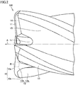
- Fig. 2 is a schematic front view showing the construction of the cutting tool according to the first embodiment.
- cutting tool 100 is a radius end mill used, for example, for working carbon fiber reinforced plastic (CFRP).
- Cutting tool 100 is revolvable, for example, around a central axis A.
- Cutting tool 100 mainly includes rake face 12, flank 11, a heel face 14, a first flute face 15, and a second flute face 17.
- Flank 11 is continuous to rake face 12.
- Heel face 14 is continuous to flank 11.
- Heel face 14 is located in the rear of flank 11 in a direction of revolution.
- a ridgeline between rake face 12 and flank 11 forms cutting edge 10.
- cutting edge 10 may include an end cutting edge 10a and a peripheral cutting edge 10b.
- Peripheral cutting edge 10b is located on an outer peripheral side relative to end cutting edge 10a.
- Flank 11 may include a first flank portion 11a and a second flank portion 11b.
- Rake face 12 may include a first rake face portion 12a and a second rake face portion 12b.
- a ridgeline between first flank portion 11a and first rake face portion 12a may form end cutting edge 10a.
- a ridgeline between second flank portion 11b and second rake face portion 12b may form peripheral cutting edge 10b.
- First flute face 15 may be continuous to second flute face 17.
- First flute face 15 may be located on the outer peripheral side relative to second flute face 17.
- Second flute face 17 may be continuous to first rake face portion 12a.
- Heel face 14 may be located closer to a shank 19 than flank 11.
- Fig. 3 is an enlarged schematic diagram of a region III in Fig. 2 .
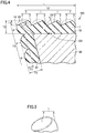
- Fig. 4 is a schematic cross-sectional view along the line IV-IV in Fig. 3 .
- cutting tool 100 mainly includes substrate 20 and diamond layer 7.
- Diamond layer 7 covers substrate 20.
- Diamond layer 7 includes rake face 12 and flank 11. In other words, each of rake face 12 and flank 11 is formed from diamond layer 7.
- Substrate 20 mainly includes top surface 22 and side surface 21. Top surface 22 is opposed to rake face 12. Side surface 21 is opposed to flank 11.
- Substrate 20 is made, for example, of cemented carbide containing powders of tungsten carbide (WC) and a binder such as cobalt (Co).
- Substrate 20 is not limited to a substrate composed of cemented carbide but may be composed, for example, of cermet or ceramics.
- Diamond layer 7 contains, for example, diamond crystals. Diamond layer 7 may be composed, for example, of polycrystalline diamond.
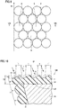
- rake face 12 when viewed in the direction perpendicular to top surface 22, rake face 12 includes a plurality of first protrusions 1.
- the plurality of first protrusions 1 may be aligned along a direction perpendicular to direction of extension B of cutting edge 10.
- the plurality of first protrusions 1 may be aligned along direction of extension B of cutting edge 10.
- the plurality of first protrusions 1 may be in contact with one another.
- a large number of first protrusions 1 may be provided. The large number means, for example, ten or more within a range of 20 ⁇ m square.
- each of the plurality of first protrusions 1 in a cross-section perpendicular to direction of extension B of cutting edge 10, each of the plurality of first protrusions 1 includes first inclined portion 2 and first curvature portion 3.
- First curvature portion 3 is continuous to first inclined portion 2.
- Each of the plurality of first protrusions 1 is constituted of first inclined portion 2 and first curvature portion 3.
- First curvature portion 3 is located opposite to cutting edge 10 with respect to first inclined portion 2.
- Each of the plurality of first protrusions 1 protrudes in a direction away from substrate 20.
- a height of first inclined portion 2 in the direction perpendicular to top surface 22 increases as a distance from cutting edge 10 increases.
- the height of first inclined portion 2 may monotonously increase as the distance from cutting edge 10 increases.
- First inclined portion 2 is inclined with respect to top surface 22.
- An angle ⁇ 1 of first inclined portion 2 with respect to top surface 22 is, for example, not smaller than 10° and not greater than 40°.
- An upper limit of angle ⁇ 1 is not particularly limited and it may be set, for example, to 80° or 30°.
- a lower limit of angle ⁇ 1 is not particularly limited and it may be set, for example, to 5° or 1°.
- straight line D2 resulting from projection of normal D3 (see Fig. 4 ) to first inclined portion 2 onto top surface 22 and normal D1 to cutting edge 10 in the direction in parallel to top surface 22 may be substantially in parallel to each other.
- straight lines D2 resulting from projection of normal D3 to inclined portion 2 onto top surface 22 may be in parallel to one another or intersect with one another.
- a portion of diamond layer 7 in contact with top surface 22 has a thickness T2, for example, of 10 ⁇ m.
- the portion of diamond layer 7 in contact with top surface 22 has thickness T2, for example, not smaller than 5 ⁇ m and not greater than 20 ⁇ m.
- each of the plurality of first protrusions 1 has a thickness T1, for example, of 3 ⁇ m.
- Each of the plurality of first protrusions 1 has thickness T1, for example, not smaller than 1 ⁇ m and not greater than 5 ⁇ m.
- first curvature portion 3 when viewed in the direction perpendicular to top surface 22, first curvature portion 3 is in a shape, for example, like a crescent.
- First curvature portion 3 includes a boundary portion 3a between the first curvature portion and first inclined portion 2 and a first outer peripheral portion 3b opposite to boundary portion 3a.
- each of boundary portion 3a and first outer peripheral portion 3b is curved as protruding away from cutting edge 10.
- Each of boundary portion 3a and first outer peripheral portion 3b may be arcuate.
- Boundary portion 3a may be greater in radius of curvature than first outer peripheral portion 3b.
- First inclined portion 2 includes a second outer peripheral portion 2a opposite to boundary portion 3a. When viewed in the direction perpendicular to top surface 22, second outer peripheral portion 2a is curved as protruding toward cutting edge 10.
- a width W4 of first inclined portion 2 in direction of extension B of cutting edge 10 may be greater than a width W2 of first inclined portion 2 in the direction perpendicular to direction of extension B of cutting edge 10 and in parallel to top surface 22.
- width W2 of first inclined portion 2 may be greater than a width W3 of first curvature portion 3.
- width W4 of first inclined portion 2 may be substantially equal to the width of first curvature portion 3.
- Width W4 of first inclined portion 2 in direction of extension B of cutting edge 10 may substantially be equal to a width W1 of first protrusion 1 in the direction perpendicular to direction of extension B of cutting edge 10 and in parallel to top surface 22.
- each of the plurality of first protrusions 1 when viewed in the direction perpendicular to top surface 22, each of the plurality of first protrusions 1 may be in a shape like a scale.
- Such an appearance that a large number of protrusions each including an inclined portion and a curvature portion are provided at a density high to some extent with orientations of the inclined portions being substantially aligned to cast crescent-shaped shade in a portion corresponding to the curvature portion to look like scales of a fish in a two-dimensional scanning electron microscope (SEM) image is herein referred to an appearance like scales.
- SEM scanning electron microscope
- the plurality of first protrusions 1 when viewed in the direction perpendicular to top surface 22, the plurality of first protrusions 1 may be provided over an area within a distance L from cutting edge 10.
- Distance L is set, for example, to 2 mm.
- Distance L is not particularly limited and it may be set to 10 ⁇ m or 500 ⁇ m.
- the plurality of first protrusions 1 are formed in an area of rake face 12 lying between cutting edge 10 and a position at distance L from cutting edge 10 in the direction perpendicular to direction of extension B of cutting edge 10.
- Distance L may be, for example, approximately as long as a depth of cut.
- the direction perpendicular to direction of extension B of cutting edge 10 means a direction perpendicular to a tangential line of cutting edge 10.
- cutting edge 10 may be defined by a boundary between first inclined portion 2 of rake face 12 and a curvature portion 9 of flank 11.
- Cutting edge 10 is formed as being sharply pointed.
- cutting edge 10 has a radius of curvature, for example, not smaller than 0.01 ⁇ m and not greater than 50 ⁇ m.
- An upper limit of the radius of curvature of cutting edge 10 is not particularly limited and it may be set, for example, to 30 ⁇ m or 10 ⁇ m.
- a lower limit of the radius of curvature of cutting edge 10 is not particularly limited and it may be set, for example, to 1 ⁇ m or 0.1 ⁇ m.
- flank 11 may include a plurality of second protrusions 4.
- each of the plurality of second protrusions 4 may include an arcuate portion.
- the plurality of second protrusions 4 may be clustered.
- a thickness T4 of the portion of diamond layer 7 in contact with side surface 21 in a direction perpendicular to side surface 21 may be greater than thickness T2 of the portion of diamond layer 7 in contact with top surface 22 in the direction perpendicular to top surface 22.
- a thickness T3 of second protrusion 4 in the direction perpendicular to side surface 21 may be greater than thickness T1 of each of the plurality of first protrusions 1 in the direction perpendicular to top surface 22.
- Fig. 5 is a schematic perspective view showing a construction of first protrusion 1 of the cutting tool according to the first embodiment.
- each of the plurality of first protrusions 1 may be, for example, in such a shape that a part of a hemisphere is cut and removed by a plane intersecting with the hemisphere.
- each of the plurality of first protrusions 1 may be constituted of substantially planar first inclined portion 2 and substantially spherical first curvature portion 3.
- First inclined portion 2 may convexly be curved.
- Fig. 6 is a flowchart schematically showing a method of manufacturing a cutting tool according to the first embodiment.
- the method of manufacturing a cutting tool according to the first embodiment mainly includes steps of covering the substrate with the diamond layer (S10: Fig. 6 ) and removing a part of the diamond layer by ion beams (S20: Fig. 6 ).
- Fig. 7 is a schematic cross-sectional view showing a first step in the method of manufacturing a cutting tool according to the first embodiment.
- substrate 20 is initially prepared.
- Substrate 20 is made, for example, of cemented carbide containing powders of tungsten carbide (WC) and a binder such as cobalt (Co).
- Substrate 20 is not limited to a substrate composed of cemented carbide but may be composed, for example, of cermet or ceramics.
- substrate 20 mainly includes top surface 22 and side surface 21. Top surface 22 is opposed to a surface to be rake face 12 of cutting tool 100. Side surface 21 is opposed to a surface to be flank 11 of cutting tool 100.
- Fig. 8 is a schematic cross-sectional view showing a second step in the method of manufacturing a cutting tool according to the first embodiment.
- Fig. 9 is a schematic plan view showing the second step in the method of manufacturing a cutting tool according to the first embodiment.
- substrate 20 is covered with diamond layer 7.
- diamond layer 7 is formed, for example, by hot filament chemical vapor deposition (HFCVD).
- Diamond layer 7 has a thickness, for example, of approximately 10 ⁇ m.
- diamond layer 7 is formed to cover top surface 22 and side surface 21.
- the surface of diamond layer 7 is formed with a plurality of protrusions 8.
- Each of the plurality of protrusions 8 is, for example, hemispherical. Specifically, the surface of the portion of diamond layer 7 opposed to top surface 22 and the surface of the portion of diamond layer 7 opposed to side surface 21 are formed with the plurality of protrusions 8.
- the step of removing a part of the diamond layer by ion beams (S20: Fig. 6 ) is performed. Specifically, a part of diamond layer 7 is removed by emission of ion beams to the surface to be rake face 12 by using an ion etching apparatus.
- oxygen ions are used for ion beams. By emitting oxygen ions to diamond layer 7, diamond layer 7 is converted to carbon monoxide or carbon dioxide. Diamond is thus vaporized and removed.
- Fig. 10 is a schematic cross-sectional view showing a third step in the method of manufacturing a cutting tool according to the first embodiment.
- Ion beams have directivity.
- ion beams are emitted from upper left in a direction inclined with respect to top surface 22.
- a part of each of the plurality of first protrusions 1 is thus removed.
- a direction of emission I of ion beams is inclined with respect to the normal to top surface 22.
- direction of emission I of ion beams may be substantially perpendicular to direction of extension B of ridgeline 23.
- EIS200-ER manufactured by Elionix Inc. can be employed as the ion etching apparatus.
- Conditions for ion etching include a time period of emission of ion beams for one hour and an applied voltage of 2500 V.
- the diamond coating is removed from substrate 20 while substrate 20 is turned around a revolution axis.
- the step of removing a part of the diamond layer is performed without turning substrate 20.
- a part of diamond layer 7 is removed while the substrate is held without varying the direction of emission of ion beams to top surface 22 of substrate 20.
- Rake face 12 including the plurality of first protrusions 1 is thus formed (see Fig. 4 ).
- each of the plurality of first protrusions 1 includes first inclined portion 2 increasing in its height in the direction perpendicular to top surface 22 as a distance from cutting edge 10 increases. Therefore, chips can smoothly pass over first inclined portion 2 of rake face 12. Consequently, ejectability of chips is improved. Therefore, damage to the cutting tool is lessened and a tool lifetime can be improved.
- angle ⁇ formed between straight line D2 resulting from projection of normal D3 to first inclined portion 2 onto top surface 22 and normal D1 to cutting edge 10 in the direction in parallel to top surface 22 is not greater than 80°.
- a direction of ejection of chips can thus substantially be in parallel to the direction of straight line D2 resulting from projection of normal D3 to first inclined portion 2 onto top surface 22. Consequently, ejectability of chips is further improved.
- the plurality of first protrusions 1 when viewed in the direction perpendicular to top surface 22, the plurality of first protrusions 1 are provided over an area within 2 mm from cutting edge 10. Chips are thus readily ejected in a most part of the area where chips pass.
- cutting edge 10 in the cross-section, has a radius of curvature not smaller than 0.01 ⁇ m and not greater than 50 ⁇ m. Sharpness can thus be improved.
- each of the plurality of protrusions 8 is removed by emission of ion beams from upper left in the direction inclined with respect to top surface 22 with top surface 22 facing up and the ridgeline between top surface 22 and side surface 21 facing to the left.
- the plurality of first protrusions 1 can thus be formed.
- Each of the plurality of first protrusions 1 includes first inclined portion 2 increasing in its height in the direction perpendicular to top surface 22 as a distance from cutting edge 10 increases. Therefore, chips can smoothly pass over first inclined portion 2 of rake face 12. Consequently, ejectability of chips is improved. Therefore, damage to the cutting tool is lessened and a tool lifetime is extended.
- the step of removing a part of diamond layer 7 is performed without turning substrate 20.
- the plurality of first protrusions 1 can thus be formed with a simplified method.
- a construction of cutting tool 100 according to a second embodiment will now be described. A feature different from that of cutting tool 100 according to the first embodiment will mainly be described below and similar description will not be repeated.
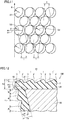
- Fig. 11 is a schematic plan view showing a construction of rake face 12 of the cutting tool according to the second embodiment.
- straight line D2 resulting from projection of the normal to inclined portion 2 onto top surface 22 may be inclined with respect to normal D1 to cutting edge 10 in the direction in parallel to top surface 22.
- angle ⁇ formed between straight line D2 resulting from projection of the normal to inclined portion 2 onto top surface 22 and normal D1 to cutting edge 10 in the direction in parallel to top surface 22 is, for example, not greater than 80°.
- Angle ⁇ may be, for example, not greater than 60° or not greater than 30°.
- straight line D2 resulting from projection of the normal to inclined portion 2 onto top surface 22 may be inclined toward the shank with respect to normal D1 to cutting edge 10 in the direction in parallel to top surface 22 or toward a side opposite to the shank (a tip end side of the cutting tool).
- the cutting tool according to the second embodiment can be formed by emission of ion beams with direction of emission I of ion beams being inclined with respect to normal D1 to direction of extension B of ridgeline 23 when viewed in the direction perpendicular to top surface 22 in the step of removing a part of diamond layer 7 by ion beams (S20: Fig. 6 ).
- the cutting tool according to the second embodiment can obtain an effect equivalent to that of the cutting tool according to the first embodiment.
- a construction of cutting tool 100 according to a third embodiment will now be described. A feature different from that of cutting tool 100 according to the first embodiment will mainly be described below and similar description will not be repeated.
- Fig. 12 is a schematic cross-sectional view showing a construction of the cutting tool according to the third embodiment.
- flank 11 may include a plurality of second protrusions 4.
- the plurality of second protrusions 4 may be aligned in the direction perpendicular to direction of extension B of cutting edge 10.
- the plurality of second protrusions 4 may be aligned along direction of extension B of cutting edge 10.
- the plurality of second protrusions 4 may be in contact with one another.
- Each of the plurality of second protrusions 4 may be in a shape like a scale. A large number of second protrusions 4 may be provided.
- each of the plurality of second protrusions 4 includes a second inclined portion 5 and a second curvature portion 6.
- Second curvature portion 6 is continuous to second inclined portion 5.
- Each of the plurality of second protrusions 4 is constituted of second inclined portion 5 and second curvature portion 6.
- Second curvature portion 6 is located opposite to cutting edge 10 with respect to second inclined portion 5.
- Each of the plurality of second protrusions 4 protrudes in a direction away from substrate 20.
- a height of second inclined portion 5 in the direction perpendicular to side surface 21 may increase as a distance from cutting edge 10 increases.
- the height of second inclined portion 5 may monotonously increase as the distance from cutting edge 10 increases.
- Second inclined portion 5 is inclined with respect to side surface 21.
- An angle ⁇ 2 of second inclined portion 5 with respect to side surface 21 may be equal to or different from angle ⁇ 1 of first inclined portion 2 with respect to top surface 22.
- Thickness T4 of the portion of diamond layer 7 in contact with side surface 21 in the direction perpendicular to side surface 21 may be substantially equal to or different from thickness T2 of the portion of diamond layer 7 in contact with top surface 22 in the direction perpendicular to top surface 22.
- Thickness T3 of a second projection in the direction perpendicular to side surface 21 may be substantially equal to or different from thickness T1 of each of the plurality of first protrusions 1 in the direction perpendicular to top surface 22.
- cutting edge 10 may be formed by a boundary between first inclined portion 2 of rake face 12 and second inclined portion 5 of flank 11. Cutting edge 10 can thus further sharply be formed.
- the cutting tool according to the third embodiment can be formed by varying the direction of emission of ion beams to substrate 20 in the step of removing a part of diamond layer 7 by ion beams (S20: Fig. 6 ). Specifically, with top surface 22 facing up and ridgeline 23 between top surface 22 and side surface 21 facing to the left, ion beams are emitted from upper left in the direction inclined with respect to top surface 22. A part of each of the plurality of first protrusions 1 is thus removed. Similarly, with side surface 21 facing up and ridgeline 23 between top surface 22 and side surface 21 facing to the left, ion beams are emitted from upper left in the direction inclined with respect to side surface 21. A part of each of the plurality of second protrusions 4 is thus removed. According to the cutting tool in the third embodiment, wear of the flank can be suppressed.
- cutting tool 100 is a radius end mill is described in the first to third embodiments, cutting tool 100 is not limited to the radius end mill.
- Cutting tool 100 may be, for example, a rotary cutting tool such as a ball end mill or a drill.
- Sample 1A is a cutting tool according to the first embodiment having a diameter of 12 mm (see Fig. 4 ).
- Fig. 13 is a schematic cross-sectional view showing a construction of the cutting tool as sample 1B.
- rake face 12 of diamond layer 7 in the cutting tool of sample 1B includes a plurality of third protrusions 31.
- each of the plurality of third protrusions 31 includes a third inclined portion 32 and a third curvature portion 33.
- Third curvature portion 33 is continuous to third inclined portion 32.
- Each of the plurality of third protrusions 31 is constituted of third inclined portion 32 and third curvature portion 33.
- Third curvature portion 33 is located opposite to cutting edge 10 with respect to third inclined portion 32.
- Each of the plurality of third protrusions 31 protrudes in a direction away from substrate 20.
- third inclined portion 32 In the cross-section, a height of third inclined portion 32 in the direction perpendicular to top surface 22 decreases as a distance from cutting edge 10 increases.
- the height of third inclined portion 32 monotonously decreases as the distance from cutting edge 10 increases.
- third inclined portion 32 extends from upper left toward lower right.
- the cutting tool of sample 1B is otherwise similar in construction to the cutting tool of sample 1A.
- Fig. 14 is a schematic cross-sectional view showing a construction of the cutting tool as sample 1C.
- rake face 12 of diamond layer 7 in the cutting tool of sample 1C includes a plurality of fourth protrusions 41.
- each of the plurality of fourth protrusions 41 includes a flat portion 42, a fourth curvature portion 43, and a fifth curvature portion 44.
- Fourth curvature portion 43 is continuous to one end of flat portion 42.
- Fifth curvature portion 44 is continuous to the other end of flat portion 42.
- Each of the plurality of fourth protrusions 41 is constituted of flat portion 42, fourth curvature portion 43, and fifth curvature portion 44.
- Fourth curvature portion 43 is located opposite to cutting edge 10 with respect to flat portion 42.
- Fifth curvature portion 44 is located on a side of cutting edge 10 with respect to flat portion 42.
- Flat portion 42 is located between fourth curvature portion 43 and fifth curvature portion 44.
- Each of the plurality of fourth protrusions 41 protrudes in the direction away from substrate 20.
- flat portion 42 is substantially in parallel to top surface 22.
- a height of fourth curvature portion 43 decreases as the distance from cutting edge 10 increases.
- a height of fifth curvature portion 44 increases as the distance form cutting edge 10 increases.
- the cutting tool of sample 1C is otherwise similar in construction to the cutting tool of sample 1A.
- amounts of wear of the rake faces of the cutting tools of samples 1A to 1C were 30 ⁇ m, 200 ⁇ m, and 60 ⁇ m, respectively.
- the diamond layer flaked away.
- the amount of wear of the rake face of the cutting tool of sample 1A was smallest. It was confirmed from the results above that the amount of wear of the rake face could be reduced by providing the inclined portion such that the height thereof in the direction perpendicular to the top surface increased as the distance from the cutting edge increased in the cross-section.
- Samples 2A to 2C are cutting tools according to the second embodiment (see Fig. 11 ) and were fabricated such that angle ⁇ thereof was set to angles shown in Table 2.
- amounts of wear of the rake faces of the cutting tools of samples 2A to 2C were 24 ⁇ m, 32 ⁇ m, and 40 ⁇ m, respectively.
- the amount of wear of the rake face was smaller as angle ⁇ was smaller. It was confirmed that the amount of wear of the rake face was within an allowable range when angle ⁇ was equal to or smaller than 80°.
- Samples 3A to 3C are cutting tools according to the first embodiment (see Fig. 4 ) and were fabricated such that distance L from the cutting edge was set as shown in Table 3.
- amounts of wear of the rake faces of the cutting tools of samples 3A to 3C were 29 ⁇ m, 32 ⁇ m, and 35 ⁇ m, respectively.
- the amount of wear of the rake face was smaller as distance L from the cutting edge was longer. It was confirmed that the amount of wear of the rake face was within an allowable range when the protrusions were provided over an area within 10 ⁇ m from the cutting edge.
- Samples 4A to 4E are cutting tools according to the first embodiment (see Fig. 4 ) and were fabricated such that the radius of curvature of the cutting edge was as shown in Table 4.
- amounts of wear of the rake faces of the cutting tools of samples 4A to 4E were 40 ⁇ m, 24 ⁇ m, 22 ⁇ m, 35 ⁇ m, and 45 ⁇ m, respectively.
- Amounts of wear of the flanks of the cutting tools of samples 4A to 4E were 40 ⁇ m, 27 ⁇ m, 26 ⁇ m, 35 ⁇ m, and 45 ⁇ m, respectively. It was confirmed from the results above that the amount of wear of the rake face and the amount of wear of the flank were small within the range of the radius of curvature of the cutting edge not smaller than 0.01 ⁇ m and not greater than 50 ⁇ m.
- first protrusion first protrusion
- 2 inclined portion first inclined portion
- 2a second outer peripheral portion 3 curvature portion (first curvature portion); 3a boundary portion; 3b first outer peripheral portion; 4 second protrusion; 5 second inclined portion; 6 second curvature portion; 7 diamond layer; 10 cutting edge; 10a end cutting edge; 10b peripheral cutting edge; 11 flank; 11a first flank portion; 11b second flank portion; 12 rake face; 12a first rake face portion; 12b second rake face portion; 14 heel face; 15 first flute face; 17 second flute face; 19 shank; 20 substrate; 21 side surface; 22 top surface; 23 ridgeline; 31 third protrusion; 32 third inclined portion; 33 third curvature portion; 41 fourth protrusion; 42 flat portion; 43 fourth curvature portion; 44 fifth curvature portion; 100 cutting tool; A central axis; B direction of extension; D1 normal to cutting edge; D2 straight line; D3 normal to inclined portion; I direction of emission; L distance; T1, T2, T3, T4 thickness; W
Landscapes
- Chemical & Material Sciences (AREA)
- Engineering & Computer Science (AREA)
- Mechanical Engineering (AREA)
- Chemical Kinetics & Catalysis (AREA)
- Materials Engineering (AREA)
- Metallurgy (AREA)
- Organic Chemistry (AREA)
- General Chemical & Material Sciences (AREA)
- Inorganic Chemistry (AREA)
- Physics & Mathematics (AREA)
- Geometry (AREA)
- Cutting Tools, Boring Holders, And Turrets (AREA)
Applications Claiming Priority (2)
| Application Number | Priority Date | Filing Date | Title |
|---|---|---|---|
| JP2017159279 | 2017-08-22 | ||
| PCT/JP2018/018739 WO2019039005A1 (fr) | 2017-08-22 | 2018-05-15 | Outil de coupe et son procédé de fabrication |
Publications (2)
| Publication Number | Publication Date |
|---|---|
| EP3674022A1 true EP3674022A1 (fr) | 2020-07-01 |
| EP3674022A4 EP3674022A4 (fr) | 2021-05-19 |
Family
ID=65438541
Family Applications (1)
| Application Number | Title | Priority Date | Filing Date |
|---|---|---|---|
| EP18847531.3A Withdrawn EP3674022A4 (fr) | 2017-08-22 | 2018-05-15 | Outil de coupe et son procédé de fabrication |
Country Status (6)
| Country | Link |
|---|---|
| US (1) | US11554421B2 (fr) |
| EP (1) | EP3674022A4 (fr) |
| JP (1) | JP7006881B2 (fr) |
| CN (1) | CN110997203B (fr) |
| TW (1) | TW201912271A (fr) |
| WO (1) | WO2019039005A1 (fr) |
Cited By (3)
| Publication number | Priority date | Publication date | Assignee | Title |
|---|---|---|---|---|
| EP4180156A4 (fr) * | 2020-07-09 | 2023-08-16 | Sumitomo Electric Hardmetal Corp. | Outil revêtu de diamant et son procédé de production |
| EP4279206A1 (fr) * | 2022-05-17 | 2023-11-22 | Rollomatic S.A. | Outil de coupe et procédé de fabrication d'un outil de coupe |
| WO2024160715A1 (fr) * | 2023-01-30 | 2024-08-08 | Element Six (Uk) Limited | Outil de coupe |
Families Citing this family (5)
| Publication number | Priority date | Publication date | Assignee | Title |
|---|---|---|---|---|
| CN109070233B (zh) * | 2016-06-29 | 2020-12-22 | 住友电工硬质合金株式会社 | 切削工具 |
| WO2021020007A1 (fr) * | 2019-08-01 | 2021-02-04 | 住友電工ハードメタル株式会社 | Procédé de fabrication d'outil de coupe, et outil de coupe |
| US12337392B2 (en) * | 2020-05-28 | 2025-06-24 | Kyocera Corporation | Coated tool and cutting tool including the same |
| EP4169643A4 (fr) * | 2020-06-22 | 2023-12-20 | Sumitomo Electric Hardmetal Corp. | Outil et procédé de production d'outil |
| CN116652227B (zh) * | 2023-05-26 | 2025-09-26 | 重庆大学 | 一种纤维增强复合材料切削刀具及其使用方法 |
Family Cites Families (10)
| Publication number | Priority date | Publication date | Assignee | Title |
|---|---|---|---|---|
| JP4420901B2 (ja) | 2003-07-31 | 2010-02-24 | 株式会社アライドマテリアル | ダイヤモンド膜被覆工具およびその製造方法 |
| JP2007307673A (ja) * | 2006-05-19 | 2007-11-29 | Osg Corp | ダイヤモンド被覆切削部材、およびその製造方法 |
| JP2009255270A (ja) * | 2008-03-27 | 2009-11-05 | Aisin Aw Co Ltd | 切削工具 |
| JP5124790B2 (ja) * | 2009-11-10 | 2013-01-23 | 住友電工ハードメタル株式会社 | ダイヤモンド被覆切削工具 |
| JP5536143B2 (ja) * | 2012-06-07 | 2014-07-02 | ユニオンツール株式会社 | 切削工具用ダイヤモンド皮膜 |
| JP5683640B2 (ja) * | 2013-05-20 | 2015-03-11 | 日本航空電子工業株式会社 | 刃物工具 |
| JP5764181B2 (ja) | 2013-10-31 | 2015-08-12 | ユニオンツール株式会社 | 硬質皮膜被覆切削工具 |
| EP3078438B1 (fr) * | 2013-12-03 | 2020-02-26 | Tungaloy Corporation | Plaquette de coupe et outil de coupe comprenant celle-ci |
| JP2017159279A (ja) | 2016-03-11 | 2017-09-14 | 大阪瓦斯株式会社 | 洗浄システム |
| CN106238758A (zh) * | 2016-08-30 | 2016-12-21 | 江苏大学 | 一种自保护控屑刀具及其加工方法 |
-
2018
- 2018-05-15 JP JP2019537921A patent/JP7006881B2/ja not_active Expired - Fee Related
- 2018-05-15 WO PCT/JP2018/018739 patent/WO2019039005A1/fr not_active Ceased
- 2018-05-15 EP EP18847531.3A patent/EP3674022A4/fr not_active Withdrawn
- 2018-05-15 US US16/639,866 patent/US11554421B2/en active Active
- 2018-05-15 CN CN201880054422.3A patent/CN110997203B/zh not_active Expired - Fee Related
- 2018-05-25 TW TW107117863A patent/TW201912271A/zh unknown
Cited By (5)
| Publication number | Priority date | Publication date | Assignee | Title |
|---|---|---|---|---|
| EP4180156A4 (fr) * | 2020-07-09 | 2023-08-16 | Sumitomo Electric Hardmetal Corp. | Outil revêtu de diamant et son procédé de production |
| EP4279206A1 (fr) * | 2022-05-17 | 2023-11-22 | Rollomatic S.A. | Outil de coupe et procédé de fabrication d'un outil de coupe |
| WO2023222822A1 (fr) * | 2022-05-17 | 2023-11-23 | Rollomatic S.A | Procédé de production d'un outil de coupe |
| US12559844B2 (en) | 2022-05-17 | 2026-02-24 | Rollomatic S.A. | Method for producing a cutting tool |
| WO2024160715A1 (fr) * | 2023-01-30 | 2024-08-08 | Element Six (Uk) Limited | Outil de coupe |
Also Published As
| Publication number | Publication date |
|---|---|
| JP7006881B2 (ja) | 2022-01-24 |
| JPWO2019039005A1 (ja) | 2020-09-17 |
| US20200361005A1 (en) | 2020-11-19 |
| EP3674022A4 (fr) | 2021-05-19 |
| US11554421B2 (en) | 2023-01-17 |
| CN110997203A (zh) | 2020-04-10 |
| CN110997203B (zh) | 2022-07-08 |
| TW201912271A (zh) | 2019-04-01 |
| WO2019039005A1 (fr) | 2019-02-28 |
Similar Documents
| Publication | Publication Date | Title |
|---|---|---|
| EP3674022A1 (fr) | Outil de coupe et son procédé de fabrication | |
| EP2923788B1 (fr) | Plaquette de coupe pour fraisage | |
| EP3053682B1 (fr) | Outil de coupe et procédé de fabrication de produit découpé au moyen de celui-ci | |
| US10946458B2 (en) | Cutting insert and drilling tool | |
| JP6828824B2 (ja) | 小径ドリルおよび小径ドリルの製造方法 | |
| CN107073597B (zh) | 钻头及使用该钻头的切削加工物的制造方法 | |
| KR20020065390A (ko) | 스로-어웨이 팁 | |
| EP3260225B1 (fr) | Insert de tournage | |
| US11376668B2 (en) | Cutting tool | |
| EP3323538B1 (fr) | Outil de coupe à revêtement de surface | |
| TWI750172B (zh) | 切削工具 | |
| US20230234143A1 (en) | Cutting insert, cutting tool, and method for manufacturing machined product | |
| US11440108B2 (en) | Rotary cutting tool | |
| US6513608B2 (en) | Cutting elements with interface having multiple abutting depressions | |
| EP3470156B1 (fr) | Outil de coupe rotatif et son procédé de fabrication | |
| EP3636370A1 (fr) | Foret | |
| JPH0780714A (ja) | 超硬質ドリル | |
| KR20010020675A (ko) | 플런지 절삭용 총형 팁 | |
| WO2006073233A1 (fr) | Plaquette d'outil de coupe | |
| JP6658805B2 (ja) | 切削インサート |
Legal Events
| Date | Code | Title | Description |
|---|---|---|---|
| STAA | Information on the status of an ep patent application or granted ep patent |
Free format text: STATUS: THE INTERNATIONAL PUBLICATION HAS BEEN MADE |
|
| PUAI | Public reference made under article 153(3) epc to a published international application that has entered the european phase |
Free format text: ORIGINAL CODE: 0009012 |
|
| STAA | Information on the status of an ep patent application or granted ep patent |
Free format text: STATUS: REQUEST FOR EXAMINATION WAS MADE |
|
| 17P | Request for examination filed |
Effective date: 20200214 |
|
| AK | Designated contracting states |
Kind code of ref document: A1 Designated state(s): AL AT BE BG CH CY CZ DE DK EE ES FI FR GB GR HR HU IE IS IT LI LT LU LV MC MK MT NL NO PL PT RO RS SE SI SK SM TR |
|
| AX | Request for extension of the european patent |
Extension state: BA ME |
|
| DAV | Request for validation of the european patent (deleted) | ||
| DAX | Request for extension of the european patent (deleted) | ||
| REG | Reference to a national code |
Ref country code: DE Ref legal event code: R079 Free format text: PREVIOUS MAIN CLASS: B23C0005160000 Ipc: B23C0005100000 |
|
| A4 | Supplementary search report drawn up and despatched |
Effective date: 20210421 |
|
| RIC1 | Information provided on ipc code assigned before grant |
Ipc: B23C 5/10 20060101AFI20210415BHEP Ipc: B23B 27/00 20060101ALI20210415BHEP Ipc: B23P 15/34 20060101ALI20210415BHEP Ipc: C23C 16/56 20060101ALI20210415BHEP Ipc: C23C 30/00 20060101ALI20210415BHEP |
|
| GRAP | Despatch of communication of intention to grant a patent |
Free format text: ORIGINAL CODE: EPIDOSNIGR1 |
|
| STAA | Information on the status of an ep patent application or granted ep patent |
Free format text: STATUS: GRANT OF PATENT IS INTENDED |
|
| INTG | Intention to grant announced |
Effective date: 20231129 |
|
| STAA | Information on the status of an ep patent application or granted ep patent |
Free format text: STATUS: THE APPLICATION IS DEEMED TO BE WITHDRAWN |
|
| 18D | Application deemed to be withdrawn |
Effective date: 20240403 |