EP3674024A1 - Schneideinsatz und schneidwerkzeug mit einem solchen schneideinsatz - Google Patents
Schneideinsatz und schneidwerkzeug mit einem solchen schneideinsatz Download PDFInfo
- Publication number
- EP3674024A1 EP3674024A1 EP18879373.1A EP18879373A EP3674024A1 EP 3674024 A1 EP3674024 A1 EP 3674024A1 EP 18879373 A EP18879373 A EP 18879373A EP 3674024 A1 EP3674024 A1 EP 3674024A1
- Authority
- EP
- European Patent Office
- Prior art keywords
- shorter
- cutting insert
- longer side
- cutting
- insert according
- Prior art date
- Legal status (The legal status is an assumption and is not a legal conclusion. Google has not performed a legal analysis and makes no representation as to the accuracy of the status listed.)
- Granted
Links
Images




Classifications
-
- B—PERFORMING OPERATIONS; TRANSPORTING
- B23—MACHINE TOOLS; METAL-WORKING NOT OTHERWISE PROVIDED FOR
- B23C—MILLING
- B23C5/00—Milling-cutters
- B23C5/02—Milling-cutters characterised by the shape of the cutter
- B23C5/10—Shank-type cutters, i.e. with an integral shaft
- B23C5/109—Shank-type cutters, i.e. with an integral shaft with removable cutting inserts
-
- B—PERFORMING OPERATIONS; TRANSPORTING
- B23—MACHINE TOOLS; METAL-WORKING NOT OTHERWISE PROVIDED FOR
- B23C—MILLING
- B23C5/00—Milling-cutters
- B23C5/16—Milling-cutters characterised by physical features other than shape
- B23C5/20—Milling-cutters characterised by physical features other than shape with removable cutter bits or teeth or cutting inserts
-
- B—PERFORMING OPERATIONS; TRANSPORTING
- B23—MACHINE TOOLS; METAL-WORKING NOT OTHERWISE PROVIDED FOR
- B23C—MILLING
- B23C5/00—Milling-cutters
- B23C5/16—Milling-cutters characterised by physical features other than shape
- B23C5/20—Milling-cutters characterised by physical features other than shape with removable cutter bits or teeth or cutting inserts
- B23C5/202—Plate-like cutting inserts with special form
-
- B—PERFORMING OPERATIONS; TRANSPORTING
- B23—MACHINE TOOLS; METAL-WORKING NOT OTHERWISE PROVIDED FOR
- B23C—MILLING
- B23C5/00—Milling-cutters
- B23C5/16—Milling-cutters characterised by physical features other than shape
- B23C5/20—Milling-cutters characterised by physical features other than shape with removable cutter bits or teeth or cutting inserts
- B23C5/202—Plate-like cutting inserts with special form
- B23C5/205—Plate-like cutting inserts with special form characterised by chip-breakers of special form
-
- B—PERFORMING OPERATIONS; TRANSPORTING
- B23—MACHINE TOOLS; METAL-WORKING NOT OTHERWISE PROVIDED FOR
- B23C—MILLING
- B23C5/00—Milling-cutters
- B23C5/16—Milling-cutters characterised by physical features other than shape
- B23C5/20—Milling-cutters characterised by physical features other than shape with removable cutter bits or teeth or cutting inserts
- B23C5/22—Securing arrangements for bits or teeth or cutting inserts
- B23C5/2204—Securing arrangements for bits or teeth or cutting inserts with cutting inserts clamped against the walls of the recess in the cutter body by a clamping member acting upon the wall of a hole in the insert
- B23C5/2208—Securing arrangements for bits or teeth or cutting inserts with cutting inserts clamped against the walls of the recess in the cutter body by a clamping member acting upon the wall of a hole in the insert for plate-like cutting inserts
- B23C5/2213—Securing arrangements for bits or teeth or cutting inserts with cutting inserts clamped against the walls of the recess in the cutter body by a clamping member acting upon the wall of a hole in the insert for plate-like cutting inserts having a special shape
-
- B—PERFORMING OPERATIONS; TRANSPORTING
- B23—MACHINE TOOLS; METAL-WORKING NOT OTHERWISE PROVIDED FOR
- B23C—MILLING
- B23C2200/00—Details of milling cutting inserts
- B23C2200/20—Top or side views of the cutting edge
- B23C2200/203—Curved cutting edges
-
- B—PERFORMING OPERATIONS; TRANSPORTING
- B23—MACHINE TOOLS; METAL-WORKING NOT OTHERWISE PROVIDED FOR
- B23C—MILLING
- B23C2200/00—Details of milling cutting inserts
- B23C2200/28—Angles
-
- B—PERFORMING OPERATIONS; TRANSPORTING
- B23—MACHINE TOOLS; METAL-WORKING NOT OTHERWISE PROVIDED FOR
- B23C—MILLING
- B23C2210/00—Details of milling cutters
- B23C2210/16—Fixation of inserts or cutting bits in the tool
- B23C2210/168—Seats for cutting inserts, supports for replacable cutting bits
-
- B—PERFORMING OPERATIONS; TRANSPORTING
- B23—MACHINE TOOLS; METAL-WORKING NOT OTHERWISE PROVIDED FOR
- B23C—MILLING
- B23C2210/00—Details of milling cutters
- B23C2210/50—Cutting inserts
Definitions
- the present disclosure relates to a cutting insert and a cutting tool having the same mounted therein.
- a cutting insert is fastened to a cutting tool mounted on a machine tool and is used for cutting a workpiece made of iron, non-ferrous metal, non-metal material, and so on.
- Such a cutting insert has a shape such that the sides connecting the upper surface and the lower surface are rotationally symmetrical with respect to each other by 180 degrees with respect to the center thereof, and thus are broadly divided into a double-sided cutting insert that can use both upper and lower surface-side cutting edges, and a single-sided cutting insert that uses only the upper surface-side cutting edge.
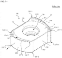
- the replaceable cutting insert is disclosed in the Korean Patent Laid-Open No. 10-2009-0108905 , which includes, as shown in FIG. 14 , an upper surface 150 and a lower surface 160 facing each other, two longitudinal side surfaces 110 and 120 and two transverse side surfaces 130 and 140 connecting the upper surface 150 and the lower surface 160, and a through hole 190 extending through the respective centers of the upper surface 150 and the lower surface 160.
- the same reference numerals are used in the background art as they are used in the Korean Patent Laid-Open No. 10-2009-0108905 , but the same reference numerals do not necessarily refer to the same components even if they overlap with the reference numerals used in the detailed description of the present disclosure to be described below.
- each of the two longitudinal side surfaces 110 and 120 is formed as a flat surface as a whole, there is a problem that the fastening force with a seat surface is decreased due to impacts applied during cutting, which allows movements on the seat surface of the cutter 200 of the milling apparatus, or the like.
- the distribution force is large and vibration easily occurs, resulting in a problem that the fastening force with the seat surface is further reduced.
- a technical object of the present disclosure is to provide a cutting insert capable of improving a fastening force with a seat surface, and a cutting tool having the same mounted therein.
- Another technical object of the present disclosure is to provide a cutting insert capable of improving rigidity as well as fastening force, and a cutting tool having the same mounted therein.
- Still another technical object of the present disclosure is to provide a cutting insert capable of improving cutting characteristics as well as fastening force, and a cutting tool having the same mounted therein.
- a cutting insert may include an upper surface and a lower surface oriented in opposite directions, a first and a second shorter side surface connecting the upper surface and the lower surface to each other and oriented in opposite directions, a first and a second longer side surfaces connecting the upper surface and the lower surface to each other, connecting the first and the second shorter side surfaces to each other, oriented in opposite directions, and being longer than the first and the second shorter side surfaces, a through hole extending through the upper surface and the lower surface, a shorter cutting edge provided at a boundary between the upper surface and the first shorter side surface, a first corner cutting edge provided at a boundary between the upper surface and a corner between the first longer side surface and the first shorter side surface, and a second corner cutting edge provided at a boundary between the upper surface and a corner between the second longer side surface and the first shorter side surface, in which, when viewed toward the upper surface, the first longer side surface may have two side portions, each side portion having an inclined shape with reference to
- first longer side surface when viewed toward the upper surface, may have a shape such that the center portion thereof is convexly protruded.
- the first longer side surface may include a convex portion which is convexly protruded and which forms a center portion, first and second inclined sections forming both sides with reference to the convex portion and gradually inclined toward an inside of the upper surface as further away from the convex portion, and first and second concave portions which are concavely recessed and which form end portions of the first and second inclined sections.
- the first longer side surface When viewed in a section cut along a vertical direction from the upper surface to the lower surface, the first longer side surface may form a vertical angle with the upper surface.
- the first shorter side surface When viewed toward the upper surface, the first shorter side surface may have an outwardly convex shape, and one side with reference to a center portion of the first shorter side surface may form an acute angle with one of the inclined sides of the first longer side surface.
- the first shorter side surface When viewed toward the upper surface, the first shorter side surface may have a curved shape as a whole or a shape that combines a curved line and a straight line.
- the shorter cutting edge When viewed toward the first shorter side surface, the shorter cutting edge may have a curved shape as a whole or a shape that combines a curved line and a straight line.
- the first corner cutting edge when viewed toward the first shorter side surface, the first corner cutting edge may be positioned higher than the second corner cutting edge, and the highest portion of the shorter cutting edge may be positioned closer to the first corner cutting edge than the second corner cutting edge.
- the first corner cutting edge when viewed toward the first shorter side surface, may be positioned lower than the second corner cutting edge, and the highest portion of the shorter cutting edge may be positioned closer to the second corner cutting edge than the first corner cutting edge.
- the first and second corner cutting edges when viewed toward the first shorter side surface, may be positioned at the same height, and the highest portion of the shorter cutting edges may be positioned closer to the center than the first and second corner cutting edges.
- the first shorter side surface When viewed toward the first longer side surface, the first shorter side surface may form a vertical angle with the upper surface.
- the shorter cutting edge When viewed toward the upper surface, the shorter cutting edge may have a curved shape that is outwardly convex.
- the first longer side surface when viewed toward the upper surface, may have a shape such that a center portion thereof is concavely recessed.
- the first longer side surface may include a concave portion which is concavely recessed and which forms a center portion, and first and second inclined sections forming both sides with reference to the concave portion and being gradually inclined as further away from the concave portion outward the upper surface.
- each of the first and second inclined sections When viewed toward the upper surface, each of the first and second inclined sections may have a straight shape.
- the upper surface may be rotationally symmetrical by 180 degrees with respect to a center thereof.
- the upper surface and the lower surface may have the same shape as each other, each of the upper and lower surfaces may be rotationally symmetrical by 180 degrees with respect to a center thereof, each of the first and second shorter side surfaces may be rotationally symmetrical by 180 degrees with respect to a center thereof, and each of the first and second longer side surfaces may be rotationally symmetrical by 180 degrees with respect to a center thereof.
- a cutting tool is a cutting tool having, mounted therein, the cutting insert according to the embodiments of the present disclosure described above, which may include a first seat surface on which the lower surface is placed, a second seat surface on which the first longer side surface is placed, and a third seat surface on which the first shorter side surface is placed, in which the second seat surface may have a first longer side inclined surface and a second longer side inclined surface on which the inclined both sides of the first longer side surface may be respectively seated.
- the third seat surface may include a shorter side inclined fastening surface on which the one side of the first shorter side surface is seated and which is adjacent to an outer circumferential surface of the cutting tool, and the shorter side inclined fastening surface may form an acute angle with any one of the first longer side inclined fastening surface and the second longer side inclined fastening surface.
- a cutting insert according to the present disclosure having the configuration as described above and a cutting tool having the same mounted therein may have the following effects.
- the technical configuration of the cutting insert according to the present disclosure includes an upper surface, a lower surface, first and second shorter side surfaces, first and second longer side surfaces, and a through hole extending through the upper and lower surfaces, in which, when viewed through the upper surface, the first longer side has a shape such that both sides thereof are inclined with reference to a center portion thereof, so that the inclined both sides are in close contact with the sheet surface of the cutting tool, and accordingly, the fastening force with the sheet surface of the cutting tool can be improved during cutting.
- the cutting insert according to the present disclosure has a shape such that, when viewed toward the upper surface, a center portion of the first longer side surface is convexly protruded, so that the through hole and the cutting tool fastening bolt inserted therein can be formed with a relatively large diameter, and accordingly, the fastening force with the cutting tool can be further improved.
- the first longer side surface when viewed toward the upper surface, has an outwardly convex shape and one side thereof with reference to the center portion of the first longer side surface forms an acute angle with one of the inclined both sides of the longer side surface, and accordingly, the fastening force with the cutting tool can be further improved.
- the first longer side surface when viewed toward the first longer side surface, forms a vertical angle (so-called negative type) with the upper surface so that, as compared with when the acute angle (so-called positive) is formed therebetween, the rigidity of the shorter cutting edge provided at the boundary between the upper face and the first longer side surface can be increased.
- the first longer side surface when viewed toward the upper surface, has a shape such that a center portion thereof is concavely recessed so that the sheet surface of the cutting tool can be protruded as much as the concave recess, that is, the web size of the cutting tool can be increased, and accordingly, the rigidity of a holder of the cutting tool can be improved.
- the shorter cutting edge when viewed toward the first longer side surface, has a curved shape or a shape that combines a curved line and a straight line, and also a curved shape that is outwardly convex when viewed toward the upper surface, so that the shorter cutting edge has an approximately helix edge structure, and accordingly, the cutting characteristics for the shorter cutting edge can be improved, and the cutting load on the shorter cutting edge can be reduced.
- the present disclosure may have other effects that can be derived from the configuration according to the present disclosure in addition to the effects described above.
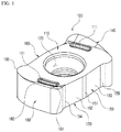
- FIG. 1 is a perspective view schematically illustrating a cutting insert according to a first embodiment of the present disclosure
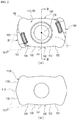
- FIG. 2 is a view of the cutting insert of FIG. 1 when viewed toward an upper surface
- FIG. 3 is a view of the cutting insert of FIG. 2 taken along the line III-III
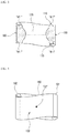
- FIG. 4 is a view of the cutting insert of FIG. 1 when viewed toward a first shorter side surface
- FIG. 5 is a view of the cutting insert of FIG. 1 when viewed toward a first longer side surface.
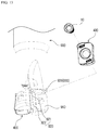
- FIG. 6 is a perspective view schematically illustrating a cutting tool having the cutting insert of FIG. 1 mounted therein.
- the cutting insert 100 includes an upper surface 110, a lower surface 120, first and second shorter side surfaces 130 and 140, first and second longer side surfaces 150 and 160, a through hole 170, a shorter cutting edge 180, a first corner cutting edge 191, and a second corner cutting edge 192, as shown in FIGS. 1 to 6 .
- each of the components will be described in detail with continued reference to FIGS. 1 to 6 .
- the upper surface 110 and the lower surface 120 may be oriented in opposite directions.
- the first and second shorter side surfaces 130 and 140 may connect the upper surface 110 and the lower surface 120 to each other and may be oriented in opposite directions, and the first and second longer side surfaces 150 and 160 may connect the upper and lower surfaces 110 and 120 to each other, connect the first and second shorter side surfaces 130 and 140 to each other, may be oriented in opposite directions, and may have a greater length than the first shorter side surface 130.
- the through hole 170 extends through the upper surface 110 and the lower surface 120 to receive a cutting tool fastening bolt (10 of FIG. 6 ) that may be inserted therein.
- the shorter cutting edge 180 is the part that cuts the workpiece and may be provided at a boundary between the upper surface 110 and the first shorter side surface 130.
- the first corner cutting edge 191 may be provided at a boundary between the upper surface 110 and a corner between the first longer side surface 150 and the first shorter side surface 130
- the second corner cutting edge 192 may be provided at a boundary between the upper surface 110 and a corner between the second longer side surface 160 and the first shorter side surface 130.
- first longer side surface 150 will be described in detail with reference to FIGS. 1 to 3 , 5 and 6 .
- the first longer side surface 150 when viewed toward the upper surface 110, may have a shape such that both sides 152 and 153 are inclined with reference to a center portion 151 thereof.
- the inclined both sides come into close contact with a first longer side inclined surface 821 and a second longer side inclined surface 822 of a second seat surface 820 of a cutting tool 800, which can improve the fastening force with the second seat surface 820 of the cutting tool 800 during cutting.
- the first longer side surface 150 when viewed toward the upper surface 110, may have a shape such that the center portion 151 thereof is convexly protruded. Accordingly, the through hole 170 and the cutting tool fastening bolt 10 inserted therein may be formed with a relatively large diameter, thereby further improving the fastening force with the cutting tool 800.
- the first longer side surface 150 when viewed toward the upper surface 110, may include a convex portion 151, first and second inclined sections 152 and 153, and first and second concave portions 154 and 155.
- the convex portion 151 may protrude convexly to form a center portion of the first longer side surface 150, and the first and second inclined sections 152 and 153 may form both sides with reference to the convex portion 151 and may be gradually inclined toward the inside of the upper surface 110 as farther away from the convex portion 151.
- the first and second concave portions 154 and 155 are concavely recessed and may form end portions of the first and second inclined sections 152 and 153, respectively.
- the through hole 170 and the cutting tool fastening bolt 10 inserted therein may be formed with a relatively large diameter, thereby further enhancing the fastening force with the cutting tool 800.
- the first longer side surface 150 may form a vertical angle ⁇ 11 (so-called "negative type") with the upper surface 110. Accordingly, compared with when an acute angle (so-called, "positive") is formed therebetween, the rigidity of the boundary between the upper surface 110 and the first longer side surface 150 can be increased.
- first shorter side surface 130 will be described in detail with reference to FIGS. 1 , 2 , and 4 to 6 .
- the first shorter side surface 130 when viewed toward the upper surface 110, the first shorter side surface 130 may have an outwardly convex shape.
- one side of the first shorter side surface 130 with reference to the center portion thereof may form an acute angle ⁇ 12 with the second inclined section 153 corresponding to one side of the inclined shape of the first longer side surface 150.
- wedge coupling may be formed between a shorter side inclined fastening surface 831 of the third seat surface 830 of the cutting tool 800 and the second longer side inclined fastening surface 822 of the second seat surface 820 (see ⁇ 14), thereby further improving the fastening force with the cutting tool 800.
- the first shorter side surface 130 when viewed toward the upper surface 110, may have a curved shape as a whole.
- the first shorter side surface 1130 when viewed toward the upper surface 110, may have a combined shape that includes a curved section 1131 forming a center portion, and first and second straight sections 1132 and 1133 that form both sides with reference to the curved section 1131.
- the first shorter side surface 130 when viewed toward the first longer side surface 150, the first shorter side surface 130 may form a vertical angle ⁇ 13 (so-called, "negative type") with the upper surface 110. Therefore, compared with when an acute angle (so-called, "positive") is formed therebetween, the rigidity of the shorter cutting edge 180 provided at the boundary between the upper surface 110 and the first shorter side surface 130 can be increased.
- the shorter cutting edge 180 when viewed toward the upper surface 110, the shorter cutting edge 180 may have a curved shape that is outwardly convex. Therefore, a convex curved shape may increase the edge strength for the shorter cutting edge 180 and reduce the contact resistance with the workpiece such that the cutting load may be reduced, which may ultimately allow the cutting insert 100 including the shorter cutting edge 180 having such a shape according to the present application to be a suitable insert for use in high feed machining.
- the center portion of the shorter cutting edge 180 may protrude most when viewed toward the upper surface 110.
- the shorter cutting edge 180 may form a curve when viewed toward the first shorter side surface 130.
- the first corner cutting edge 191 when viewed toward the first shorter side surface 130, the first corner cutting edge 191 may be positioned higher than the second corner cutting edge 192, and the highest portion of the shorter cutting edge 180 may be positioned closer to the first corner cutting edge 191 than the second corner cutting edge 192.
- the shorter cutting edge 180 is curved when viewed toward the first shorter side surface 130 (see FIG. 4 ), and also has a curved shape that is outwardly convex (see FIG. 2A ) or a shape that combines a curved line and a straight line (see FIG. 2B ) when viewed toward the upper surface 110, the shorter cutting edge 180 has an approximately helix edge structure, which can improve the cutting characteristics for the shorter cutting edge 180 and reduce the cutting load on the shorter cutting edge 180.
- the technical characteristics of the cutting insert 100 according to the first embodiment of the present disclosure described above may be applied to both the single-sided cutting insert and the double-sided cutting insert.
- the upper surface 110 When applied to the single-sided cutting insert, the upper surface 110 may have a structure that is rotationally symmetrical by 180 degrees with respect to the center C1 thereof, as shown in FIG. 2 .
- the cutting insert 100 may alternately use, as a cutting edge, two corners placed in diagonal directions with respect to the cutting tool (see 800 in FIG. 6 ) rotated in either direction.
- a chip breaker (111 of FIG. 1 ) may be formed at portions corresponding to the two corners of the upper surface 110 such that the cut portion of the workpiece is curled and cut.
- each of the upper surface 110 and the lower surface 120 is rotated by 180 degrees with respect to the center (C1 of FIG. 2 ) thereof, each of the first and second shorter side surfaces 130 and 140 is rotationally symmetrical by 180 degrees with respect to the center (C2 of FIG. 4 ) thereof, and each of the first and second longer sides 150 and 160 is rotationally symmetrical by 180 degrees with respect to the center (C3 in FIG. 5 ) thereof.
- FIGS. 1 the upper surface 110 and the lower surface 120
- each of the first and second shorter side surfaces 130 and 140 is rotationally symmetrical by 180 degrees with respect to the center (C2 of FIG. 4 ) thereof
- each of the first and second longer sides 150 and 160 is rotationally symmetrical by 180 degrees with respect to the center (C3 in FIG. 5 ) thereof.
- the cutting insert 100 may alternately use, as the cutting edge, the two corners placed diagonally on the upper surface 110 and the two corners placed diagonally on the lower surface 120, with respect to the cutting tool (see 800 in FIG. 6 ) rotated in either direction.
- the cutting tool 800 is a cutting tool in which the cutting insert 100 according to the first embodiment of the present disclosure described above is mounted, and includes a first seat surface 810, a second seat surface 820, and a third seat surface 830 provided in a pocket portion thereof.
- the first seat surface 810 is where the lower surface 120 of the cutting insert 100 described above is placed
- the second seat surface 820 is where the first shorter side surface 130 of the cutting insert 100 described above is placed
- the third seat surface 830 is where the first longer side surface 150 of the cutting insert 100 described above is placed.
- the second seat surface 820 may include the first longer side inclined fastening surface 821 and the second longer side inclined fastening surface 822 where the first and second inclined sections 152 and 153 corresponding to both inclined sides of the first longer side surface are respectively seated
- the third seat surface 830 may include the shorter side inclined fastening surface 831 on which one side of the first shorter side surface is seated, and which is adjacent the outer circumferential surface of the cutting tool, and the shorter side inclined fastening surface 831 may form an acute angle ⁇ 14 with the second longer side inclined fastening surface. Therefore, the cutting insert 100 described above may be wedge-coupled between the shorter side inclined fastening surface 831 and the second longer side inclined fastening surface of the cutting tool, and the fastening force is improved.
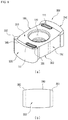
- FIG. 7A is a perspective view of the cutting insert according to the second embodiment of the present disclosure
- FIG. 7B is a schematic view when viewed toward the first shorter side surface thereof.
- the cutting insert 200 according to the second embodiment of the present disclosure is the same as the first embodiment of the present disclosure described above except for a shorter cutting edge 280, first and second corner cutting edges 291 and 292, and the like, associated with the change in shape of first and second shorter side surfaces 230 and 240, which will be mainly described below.
- the first corner cutting edge 291 when viewed toward the first shorter side surface 230, the first corner cutting edge 291 may be positioned lower than the second corner cutting edge 292, and the highest portion of the shorter cutting edge 280 may be positioned closer to the second corner cutting edge 292 than the first corner cutting edge 291.
- the shorter cutting edge 280 is curved in a shape that is outwardly convex when viewed toward the upper surface 210 (see FIGS. 2 and 7A ), and also has a shape that combines a curved line and a straight line (see FIG. 7B ) when viewed toward the first shorter side surface 230, the shorter cutting edge 280 has an approximately helix edge structure, which can improve the cutting characteristics for the shorter cutting edge 280 and reduce the cutting load on the shorter cutting edge 280.
- FIG. 8A is a perspective view of the cutting insert according to the second embodiment of the present disclosure
- FIG. 8B is a schematic view when viewed toward the first shorter side surface thereof.
- the cutting insert 300 according to the third embodiment of the present disclosure is the same as the first embodiment of the present disclosure described above except for a shorter cutting edge 380, first and second corner cutting edges 391 and 392, and the like, associated with the change in shape of first and second shorter side surfaces 330 and 340, which will be mainly described below.
- the first and second corner cutting edges 391 and 392 when viewed toward the first shorter side surface 330, the first and second corner cutting edges 391 and 392 may be positioned at the same height, and the highest portion of the shorter cutting edge 380 may be positioned closer to the center than the first and second corner cutting edges 391 and 392.
- the shorter cutting edge 380 is curved in a shape that is outwardly convex when viewed toward the upper surface 310 (see FIGS. 2 and 8A ), and also has a convex curve (see FIG. 8B ) when viewed toward the first shorter side surface 330, the shorter cutting edge 380 has an approximately helix edge structure, which can improve the cutting characteristics for the shorter cutting edge 380 and reduce the cutting load on the shorter cutting edge 380.
- FIG. 9 is a perspective view schematically illustrating the cutting insert according to the fourth embodiment of the present disclosure
- FIG. 10 is a view of the cutting insert of FIG. 9 when viewed toward the upper surface
- FIG. 11 is a view of the cutting insert of FIG. 10 taken along the line XI-XI
- FIG. 12 is a view of the cutting insert of FIG. 9 when viewed toward the first longer side surface.
- FIG. 13 is a perspective view schematically illustrating a cutting tool having the cutting insert of FIG. 9 mounted therein.
- the cutting insert 400 according to the fourth embodiment of the present disclosure is the same as the first embodiment of the present disclosure described above except for first and second longer side surfaces 450 and 460, the upper surface 410, the lower surface 420, and the like, which will be mainly described below.
- the first longer side surface 450 when viewed toward the upper surface 410, the first longer side surface 450 may have a shape such that both sides 452 and 453 are inclined with reference to a center portion 451 thereof.
- the inclined both sides come into close contact with a first longer side inclined surface 921 and a second longer side inclined surface 922 of a second seat surface 920 of a cutting tool 900, which can improve the fastening force with the second seat surface 920 of the cutting tool 900 during cutting.
- the first longer side surface 450 when viewed toward the upper surface 410, the first longer side surface 450 may have a shape such that a center portion thereof is concavely recessed. Accordingly, as shown in FIG. 13 , the second seat surface 920 of the cutting tool 900 may be protruded as much as the concave recess, that is, the web size of the cutting tool 900 may be increased, and this can further improve the holder rigidity of the cutting tool 900.
- the first longer side surface 450 may include the concave portion 451 and the first and second inclined sections 452 and 453.
- the concave portion 451 is concavely recessed and may form the center portion of the first longer side surface 450
- the first and second inclined sections 452 and 453 may form both sides with reference to the concave portion and may be gradually inclined as further away from the concave portion 451 outward the upper surface 410.
- the first and second inclined sections 452 and 453 come into close contact with the first longer side inclined surface 921 and the second longer side inclined surface 922 of the second seat surface 920 of the cutting tool 900, and this can improve the fastening force with the second seat surface 920 of the cutting tool 900 during cutting.
- the first longer side surface 450 may form a vertical angle ⁇ 41 (so-called "negative type") with the upper surface 410. Accordingly, compared with when an acute angle (so-called, "positive") is formed therebetween, the rigidity of the boundary between the upper surface 410 and the first longer side surface 450 can be increased.
- one side of the first shorter side surface 130 with reference to the center portion thereof may form an acute angle ⁇ 42 with the first inclined section 452 corresponding to one side of the inclined shape of the first longer side surface 450.
- wedge coupling may be formed between a shorter side inclined fastening surface 931 of the third seat surface 930 of the cutting tool 900 and the first longer side inclined fastening surface 921 of the second seat surface 920 (see ⁇ 44), thereby still further improving the fastening force with the cutting tool 900.
- the first shorter side surface 130 when viewed toward the first longer side surface 450, the first shorter side surface 130 may form a vertical angle ⁇ 43 (so-called, "negative type") with the upper surface 410. Therefore, compared with when an acute angle (so-called, "positive") is formed therebetween, the rigidity of the shorter cutting edge 180 provided at the boundary between the upper surface 410 and the first shorter side surface 130 can be increased.
- the cutting tool 900 is a cutting tool in which the cutting insert 400 according to the fourth embodiment of the present disclosure described above is mounted, and includes a first seat surface 910, a second seat surface 920, and a third seat surface 930 provided in a pocket portion thereof.
- the first seat surface 910 is where the lower surface 420 of the cutting insert 400 described above is placed
- the second seat surface 920 is where the first shorter side surface 130 of the cutting insert 400 described above is placed
- the third seat surface 930 is where the first longer side surface 450 of the cutting insert 400 described above is placed.
- the second seat surface 920 may include the first longer side inclined fastening surface 921 and the second longer side inclined fastening surface 922 where the first and second inclined sections 452 and 453 corresponding to both inclined sides of the first longer side surface 450 are respectively seated
- the third seat surface 930 may include the shorter side inclined fastening surface 931 on which one side of the first shorter side surface 130 is seated, and which is adjacent the outer circumferential surface of the cutting tool 900, and the shorter side inclined fastening surface 931 may form an acute angle ⁇ 44 with the first longer side inclined fastening surface 921. Therefore, the cutting insert 400 described above may be wedge-coupled between the shorter side inclined fastening surface 931 and the first longer side inclined fastening surface 921 of the cutting tool 900, and the fastening force is improved.
- a cutting insert according to the present disclosure is fastened to a cutting tool mounted in a machine tool and is used for cutting a workpiece made of iron, non-ferrous metal, non-metal material, and so on.
Landscapes
- Engineering & Computer Science (AREA)
- Mechanical Engineering (AREA)
- Milling Processes (AREA)
Applications Claiming Priority (2)
| Application Number | Priority Date | Filing Date | Title |
|---|---|---|---|
| KR1020170151632A KR102015290B1 (ko) | 2017-11-14 | 2017-11-14 | 절삭 인서트 및 이를 장착한 절삭 공구 |
| PCT/KR2018/010107 WO2019098508A1 (ko) | 2017-11-14 | 2018-08-31 | 절삭 인서트 및 이를 장착한 절삭 공구 |
Publications (3)
| Publication Number | Publication Date |
|---|---|
| EP3674024A1 true EP3674024A1 (de) | 2020-07-01 |
| EP3674024A4 EP3674024A4 (de) | 2021-06-02 |
| EP3674024B1 EP3674024B1 (de) | 2024-08-28 |
Family
ID=66538645
Family Applications (1)
| Application Number | Title | Priority Date | Filing Date |
|---|---|---|---|
| EP18879373.1A Active EP3674024B1 (de) | 2017-11-14 | 2018-08-31 | Schneideinsatz und schneidwerkzeug mit einem solchen schneideinsatz |
Country Status (6)
| Country | Link |
|---|---|
| US (1) | US11389883B2 (de) |
| EP (1) | EP3674024B1 (de) |
| KR (1) | KR102015290B1 (de) |
| CN (1) | CN111511493B (de) |
| RU (1) | RU2744729C1 (de) |
| WO (1) | WO2019098508A1 (de) |
Cited By (1)
| Publication number | Priority date | Publication date | Assignee | Title |
|---|---|---|---|---|
| EP4670883A1 (de) * | 2024-06-28 | 2025-12-31 | AB Sandvik Coromant | Doppelseitige wendeschneidplatte und fräswerkzeug mit hoher vorschubgeschwindigkeit |
Families Citing this family (7)
| Publication number | Priority date | Publication date | Assignee | Title |
|---|---|---|---|---|
| EP3556498B1 (de) * | 2018-04-16 | 2021-02-17 | Seco Tools Ab | Schneideeinsatz und fräswerkzeug |
| US11969807B2 (en) | 2020-01-15 | 2024-04-30 | Taegutec Ltd. | Insert and cutting tool assembly comprising same |
| JP6940832B1 (ja) * | 2020-09-07 | 2021-09-29 | 株式会社タンガロイ | 転削工具 |
| CN114799293B (zh) * | 2022-06-30 | 2023-03-21 | 中国空气动力研究与发展中心高速空气动力研究所 | 一种风洞复杂曲面收缩段的加工方法 |
| JPWO2024105785A1 (de) * | 2022-11-15 | 2024-05-23 | ||
| JP2025079309A (ja) * | 2024-09-02 | 2025-05-21 | ダイジ▲ェ▼ット工業株式会社 | 切削用インサート及び刃先交換式切削工具 |
| CN118848041B (zh) * | 2024-09-26 | 2025-02-11 | 赣州澳克泰工具技术有限公司 | 切削刀片以及切削刀具 |
Family Cites Families (43)
| Publication number | Priority date | Publication date | Assignee | Title |
|---|---|---|---|---|
| SE455676B (sv) * | 1984-11-12 | 1988-08-01 | Sandvik Ab | Korthalsborr, samt sker derfor |
| CA2062213C (en) * | 1992-03-03 | 1996-07-16 | Alfonso Minicozzi | Indexable cutting insert for rotary cutting tools |
| SE470093B (sv) * | 1992-04-02 | 1993-11-08 | Sandvik Ab | Skär för skiv- eller planfräsar, samt fräsverktyg för sådana skär |
| DE9215855U1 (de) * | 1992-11-21 | 1994-03-24 | Widia GmbH, 45145 Essen | Schneideinsatz |
| DE4239236C2 (de) * | 1992-11-21 | 1997-06-26 | Widia Gmbh | Schneideinsatz |
| SE504315C2 (sv) * | 1994-05-09 | 1997-01-13 | Sandvik Ab | Borr för metallborrning |
| SE519133C2 (sv) * | 1998-10-13 | 2003-01-21 | Sandvik Ab | Borrskär för metallborrning |
| IL127175A (en) * | 1998-11-20 | 2003-06-24 | Iscar Ltd | Cutting insert for mounting on a milling cutter |
| DE10043016B4 (de) * | 2000-09-01 | 2006-11-23 | Walter Ag | Bohrnutenfräser |
| AT5969U1 (de) * | 2001-12-21 | 2003-02-25 | Plansee Tizit Ag | Fräswerkzeug |
| DE10346790A1 (de) * | 2003-10-08 | 2005-05-04 | Kennametal Widia Gmbh & Co Kg | Schneideinsatz |
| US7040844B1 (en) * | 2005-03-08 | 2006-05-09 | Mitsubishi Materials Corporation | Throwaway insert and throwaway-type rotary cutting tool |
| KR100854278B1 (ko) * | 2006-12-28 | 2008-08-26 | 한국야금 주식회사 | 다기능 절삭공구 |
| US8979443B2 (en) * | 2007-12-28 | 2015-03-17 | Kyocera Corporation | Insert for drill |
| KR100958403B1 (ko) | 2008-04-14 | 2010-05-18 | 대구텍 유한회사 | 교환 가능한 절삭 인서트 |
| JP5568548B2 (ja) * | 2008-04-14 | 2014-08-06 | テグテック・リミテッド | 交換可能な切削インサート |
| CA2757400A1 (en) * | 2009-04-02 | 2010-10-07 | Tungaloy Corporation | Cutting insert and cutting edge replaceable cutting tool |
| CN103025462B (zh) * | 2010-08-11 | 2015-03-18 | 京瓷株式会社 | 切削镶刀及切削工具、以及使用该切削工具的切削加工物的制造方法 |
| JP5589244B2 (ja) * | 2010-10-06 | 2014-09-17 | 大昭和精機株式会社 | インサート |
| KR101239036B1 (ko) * | 2011-01-17 | 2013-03-04 | 대구텍 유한회사 | 직각 가공용 절삭 인서트 및 이를 구비한 밀링 커터 |
| CN103619517B (zh) * | 2011-06-30 | 2016-04-06 | 京瓷株式会社 | 切削镶刀及切削工具、以及使用该切削工具的切削加工物的制造方法 |
| DE102012014092B4 (de) * | 2011-07-22 | 2020-12-17 | Kennametal India Ltd. | Indexierbarer Bohreinsatz sowie Bohrkörper mit indexierbarem Bohreinsatz |
| AT12630U1 (de) * | 2011-08-26 | 2012-09-15 | Ceratizit Austria Gmbh | Doppelseitiger schneideinsatz zum fräsen |
| US9796032B2 (en) | 2012-12-27 | 2017-10-24 | Tungaloy Corporation | Cutting insert and indexable rotary cutting tool |
| US9314851B2 (en) * | 2013-05-21 | 2016-04-19 | Iscar, Ltd. | Cutting insert having a rearwardly offset cutting edge and cutting tool |
| JP6420239B2 (ja) * | 2013-06-27 | 2018-11-07 | 京セラ株式会社 | 切削インサート、切削工具および切削加工物の製造方法 |
| JP6151782B2 (ja) * | 2013-07-18 | 2017-06-21 | 京セラ株式会社 | 切削インサート、切削工具および切削加工物の製造方法 |
| US10058935B2 (en) * | 2013-11-20 | 2018-08-28 | Kyocera Corporation | Cutting insert, cutting tool, and method of manufacturing machined product |
| US9358622B2 (en) * | 2013-11-21 | 2016-06-07 | Iscar, Ltd. | Single sided indexable ramping milling insert and ramping milling tool |
| EP3100811B1 (de) * | 2014-01-28 | 2022-09-21 | MOLDINO Tool Engineering, Ltd. | Schneideinsatz und rotierendes schneidwerkzeug |
| JP5888656B2 (ja) * | 2014-06-02 | 2016-03-22 | 住友電工ハードメタル株式会社 | 切削インサートとフライスカッタ |
| KR20160009242A (ko) * | 2014-07-16 | 2016-01-26 | 대구텍 유한회사 | 절삭 인서트 및 이를 포함하는 절삭 공구 |
| EP3199282B1 (de) * | 2014-09-26 | 2020-07-29 | KYOCERA Corporation | Schneideinsatz, schneidwerkzeug sowie verfahren zur herstellung eines zerschnittenen artikels |
| EP3009217B1 (de) * | 2014-10-13 | 2017-07-05 | Sandvik Intellectual Property AB | Tangentialer Schneideinsatz und Fräswerkzeug mit einem derartigen Schneideinsatz |
| CN107000082B (zh) * | 2015-03-05 | 2020-03-13 | 株式会社泰珂洛 | 切削刀片以及刀尖更换式旋转切削刀具 |
| CN107405702B (zh) * | 2015-05-19 | 2019-09-27 | 株式会社泰珂洛 | 工具体以及切削工具 |
| CN107635704B (zh) * | 2015-06-19 | 2020-01-07 | 株式会社泰珂洛 | 工具体及切削工具 |
| KR101814642B1 (ko) * | 2015-11-04 | 2018-01-03 | 한국야금 주식회사 | 고이송 양면형 절삭 인서트 및 이를 장착한 절삭 공구 |
| JP6616176B2 (ja) * | 2015-12-24 | 2019-12-04 | 京セラ株式会社 | 切削工具 |
| JP6562983B2 (ja) * | 2017-08-10 | 2019-08-21 | 株式会社タンガロイ | 切削インサート及び切削工具 |
| US10307840B1 (en) * | 2017-11-28 | 2019-06-04 | Iscar, Ltd. | Double-sided indexable insert having tapered waist for high-feed milling and drilling |
| EP3593928B1 (de) * | 2018-07-10 | 2021-02-24 | AB Sandvik Coromant | Tangentialer schneideinsatz und fräswerkzeug |
| US11850670B2 (en) * | 2020-04-24 | 2023-12-26 | Kennametal India Ltd. | Milling cutting inserts |
-
2017
- 2017-11-14 KR KR1020170151632A patent/KR102015290B1/ko active Active
-
2018
- 2018-08-31 RU RU2020119202A patent/RU2744729C1/ru active
- 2018-08-31 US US16/757,994 patent/US11389883B2/en active Active
- 2018-08-31 EP EP18879373.1A patent/EP3674024B1/de active Active
- 2018-08-31 CN CN201880073488.7A patent/CN111511493B/zh active Active
- 2018-08-31 WO PCT/KR2018/010107 patent/WO2019098508A1/ko not_active Ceased
Cited By (2)
| Publication number | Priority date | Publication date | Assignee | Title |
|---|---|---|---|---|
| EP4670883A1 (de) * | 2024-06-28 | 2025-12-31 | AB Sandvik Coromant | Doppelseitige wendeschneidplatte und fräswerkzeug mit hoher vorschubgeschwindigkeit |
| WO2026002550A1 (en) * | 2024-06-28 | 2026-01-02 | Ab Sandvik Coromant | Double-sided indexable cutting insert and high feed milling tool |
Also Published As
| Publication number | Publication date |
|---|---|
| EP3674024A4 (de) | 2021-06-02 |
| US11389883B2 (en) | 2022-07-19 |
| US20200338652A1 (en) | 2020-10-29 |
| KR102015290B1 (ko) | 2019-08-28 |
| CN111511493A (zh) | 2020-08-07 |
| WO2019098508A1 (ko) | 2019-05-23 |
| RU2744729C1 (ru) | 2021-03-15 |
| EP3674024B1 (de) | 2024-08-28 |
| KR20190054725A (ko) | 2019-05-22 |
| CN111511493B (zh) | 2023-09-15 |
Similar Documents
| Publication | Publication Date | Title |
|---|---|---|
| EP3674024B1 (de) | Schneideinsatz und schneidwerkzeug mit einem solchen schneideinsatz | |
| EP3233341B1 (de) | Verstärkter doppelseitiger schneideinsatz und schneidwerkzeug mit verstärktem doppelseitigem schneideinsatz | |
| US10112241B2 (en) | Insert, tool holder, and assembly thereof | |
| KR101517979B1 (ko) | 절삭 인서트 및 이를 장착한 절삭 공구 | |
| KR20100016473A (ko) | 8날 절삭 인서트 및 이를 위한 공구 홀더 | |
| US10556277B2 (en) | Double-sided cutting insert having high feed rate and cutting tool equipped therewith | |
| CN114616064B (zh) | 切削刀片和配备该切削刀片的切削刀具 | |
| WO2014081010A1 (ja) | 切削インサート及びその製造方法 | |
| US11117202B2 (en) | High-feed cutting insert and cutting tool equipped with same | |
| KR101469135B1 (ko) | 절삭 인서트 및 이를 장착한 절삭 공구 | |
| US11117201B2 (en) | Single-sided high feed cutting insert and cutting tool equipped with same | |
| US10259055B2 (en) | Cutting insert | |
| KR101556737B1 (ko) | 절삭 인서트 및 이를 장착한 절삭 공구 | |
| JP5109485B2 (ja) | 旋削用スローアウェイチップ | |
| JPH0621612Y2 (ja) | スローアウエイチップ | |
| JP6728428B1 (ja) | 切削インサート及び切削工具 | |
| RU2786272C1 (ru) | Режущая пластина и режущий инструмент, снабженный такой пластиной | |
| KR101905664B1 (ko) | 고이송 절삭 인서트 및 이를 장착한 절삭 공구 | |
| JP2023140805A (ja) | 切削インサート |
Legal Events
| Date | Code | Title | Description |
|---|---|---|---|
| STAA | Information on the status of an ep patent application or granted ep patent |
Free format text: STATUS: THE INTERNATIONAL PUBLICATION HAS BEEN MADE |
|
| PUAI | Public reference made under article 153(3) epc to a published international application that has entered the european phase |
Free format text: ORIGINAL CODE: 0009012 |
|
| STAA | Information on the status of an ep patent application or granted ep patent |
Free format text: STATUS: REQUEST FOR EXAMINATION WAS MADE |
|
| 17P | Request for examination filed |
Effective date: 20200324 |
|
| AK | Designated contracting states |
Kind code of ref document: A1 Designated state(s): AL AT BE BG CH CY CZ DE DK EE ES FI FR GB GR HR HU IE IS IT LI LT LU LV MC MK MT NL NO PL PT RO RS SE SI SK SM TR |
|
| AX | Request for extension of the european patent |
Extension state: BA ME |
|
| DAV | Request for validation of the european patent (deleted) | ||
| DAX | Request for extension of the european patent (deleted) | ||
| A4 | Supplementary search report drawn up and despatched |
Effective date: 20210504 |
|
| RIC1 | Information provided on ipc code assigned before grant |
Ipc: B23C 5/20 20060101AFI20210428BHEP Ipc: B23C 5/10 20060101ALI20210428BHEP Ipc: B23C 5/22 20060101ALI20210428BHEP |
|
| STAA | Information on the status of an ep patent application or granted ep patent |
Free format text: STATUS: EXAMINATION IS IN PROGRESS |
|
| 17Q | First examination report despatched |
Effective date: 20231103 |
|
| GRAP | Despatch of communication of intention to grant a patent |
Free format text: ORIGINAL CODE: EPIDOSNIGR1 |
|
| STAA | Information on the status of an ep patent application or granted ep patent |
Free format text: STATUS: GRANT OF PATENT IS INTENDED |
|
| INTG | Intention to grant announced |
Effective date: 20240405 |
|
| RIN1 | Information on inventor provided before grant (corrected) |
Inventor name: AHN, SUN YONG Inventor name: KIM, YOUNG HEUM Inventor name: LEE, SANG YONG Inventor name: CHOI, YOUNG NAM |
|
| GRAS | Grant fee paid |
Free format text: ORIGINAL CODE: EPIDOSNIGR3 |
|
| P01 | Opt-out of the competence of the unified patent court (upc) registered |
Free format text: CASE NUMBER: APP_35764/2024 Effective date: 20240614 |
|
| GRAA | (expected) grant |
Free format text: ORIGINAL CODE: 0009210 |
|
| STAA | Information on the status of an ep patent application or granted ep patent |
Free format text: STATUS: THE PATENT HAS BEEN GRANTED |
|
| AK | Designated contracting states |
Kind code of ref document: B1 Designated state(s): AL AT BE BG CH CY CZ DE DK EE ES FI FR GB GR HR HU IE IS IT LI LT LU LV MC MK MT NL NO PL PT RO RS SE SI SK SM TR |
|
| REG | Reference to a national code |
Ref country code: GB Ref legal event code: FG4D |
|
| REG | Reference to a national code |
Ref country code: CH Ref legal event code: EP |
|
| REG | Reference to a national code |
Ref country code: DE Ref legal event code: R096 Ref document number: 602018073777 Country of ref document: DE |
|
| REG | Reference to a national code |
Ref country code: IE Ref legal event code: FG4D |
|
| REG | Reference to a national code |
Ref country code: LT Ref legal event code: MG9D |
|
| PG25 | Lapsed in a contracting state [announced via postgrant information from national office to epo] |
Ref country code: NO Free format text: LAPSE BECAUSE OF FAILURE TO SUBMIT A TRANSLATION OF THE DESCRIPTION OR TO PAY THE FEE WITHIN THE PRESCRIBED TIME-LIMIT Effective date: 20241128 |
|
| REG | Reference to a national code |
Ref country code: AT Ref legal event code: MK05 Ref document number: 1717421 Country of ref document: AT Kind code of ref document: T Effective date: 20240828 |
|
| PG25 | Lapsed in a contracting state [announced via postgrant information from national office to epo] |
Ref country code: NL Free format text: LAPSE BECAUSE OF FAILURE TO SUBMIT A TRANSLATION OF THE DESCRIPTION OR TO PAY THE FEE WITHIN THE PRESCRIBED TIME-LIMIT Effective date: 20240828 Ref country code: PL Free format text: LAPSE BECAUSE OF FAILURE TO SUBMIT A TRANSLATION OF THE DESCRIPTION OR TO PAY THE FEE WITHIN THE PRESCRIBED TIME-LIMIT Effective date: 20240828 Ref country code: GR Free format text: LAPSE BECAUSE OF FAILURE TO SUBMIT A TRANSLATION OF THE DESCRIPTION OR TO PAY THE FEE WITHIN THE PRESCRIBED TIME-LIMIT Effective date: 20241129 Ref country code: PT Free format text: LAPSE BECAUSE OF FAILURE TO SUBMIT A TRANSLATION OF THE DESCRIPTION OR TO PAY THE FEE WITHIN THE PRESCRIBED TIME-LIMIT Effective date: 20241230 Ref country code: FI Free format text: LAPSE BECAUSE OF FAILURE TO SUBMIT A TRANSLATION OF THE DESCRIPTION OR TO PAY THE FEE WITHIN THE PRESCRIBED TIME-LIMIT Effective date: 20240828 |
|
| PG25 | Lapsed in a contracting state [announced via postgrant information from national office to epo] |
Ref country code: BG Free format text: LAPSE BECAUSE OF FAILURE TO SUBMIT A TRANSLATION OF THE DESCRIPTION OR TO PAY THE FEE WITHIN THE PRESCRIBED TIME-LIMIT Effective date: 20240828 |
|
| PG25 | Lapsed in a contracting state [announced via postgrant information from national office to epo] |
Ref country code: LV Free format text: LAPSE BECAUSE OF FAILURE TO SUBMIT A TRANSLATION OF THE DESCRIPTION OR TO PAY THE FEE WITHIN THE PRESCRIBED TIME-LIMIT Effective date: 20240828 |
|
| REG | Reference to a national code |
Ref country code: NL Ref legal event code: MP Effective date: 20240828 |
|
| PG25 | Lapsed in a contracting state [announced via postgrant information from national office to epo] |
Ref country code: IS Free format text: LAPSE BECAUSE OF FAILURE TO SUBMIT A TRANSLATION OF THE DESCRIPTION OR TO PAY THE FEE WITHIN THE PRESCRIBED TIME-LIMIT Effective date: 20241228 Ref country code: AT Free format text: LAPSE BECAUSE OF FAILURE TO SUBMIT A TRANSLATION OF THE DESCRIPTION OR TO PAY THE FEE WITHIN THE PRESCRIBED TIME-LIMIT Effective date: 20240828 |
|
| PG25 | Lapsed in a contracting state [announced via postgrant information from national office to epo] |
Ref country code: HR Free format text: LAPSE BECAUSE OF FAILURE TO SUBMIT A TRANSLATION OF THE DESCRIPTION OR TO PAY THE FEE WITHIN THE PRESCRIBED TIME-LIMIT Effective date: 20240828 |
|
| PG25 | Lapsed in a contracting state [announced via postgrant information from national office to epo] |
Ref country code: ES Free format text: LAPSE BECAUSE OF FAILURE TO SUBMIT A TRANSLATION OF THE DESCRIPTION OR TO PAY THE FEE WITHIN THE PRESCRIBED TIME-LIMIT Effective date: 20240828 Ref country code: RS Free format text: LAPSE BECAUSE OF FAILURE TO SUBMIT A TRANSLATION OF THE DESCRIPTION OR TO PAY THE FEE WITHIN THE PRESCRIBED TIME-LIMIT Effective date: 20241128 |
|
| PG25 | Lapsed in a contracting state [announced via postgrant information from national office to epo] |
Ref country code: RS Free format text: LAPSE BECAUSE OF FAILURE TO SUBMIT A TRANSLATION OF THE DESCRIPTION OR TO PAY THE FEE WITHIN THE PRESCRIBED TIME-LIMIT Effective date: 20241128 Ref country code: PT Free format text: LAPSE BECAUSE OF FAILURE TO SUBMIT A TRANSLATION OF THE DESCRIPTION OR TO PAY THE FEE WITHIN THE PRESCRIBED TIME-LIMIT Effective date: 20241230 Ref country code: PL Free format text: LAPSE BECAUSE OF FAILURE TO SUBMIT A TRANSLATION OF THE DESCRIPTION OR TO PAY THE FEE WITHIN THE PRESCRIBED TIME-LIMIT Effective date: 20240828 Ref country code: NO Free format text: LAPSE BECAUSE OF FAILURE TO SUBMIT A TRANSLATION OF THE DESCRIPTION OR TO PAY THE FEE WITHIN THE PRESCRIBED TIME-LIMIT Effective date: 20241128 Ref country code: NL Free format text: LAPSE BECAUSE OF FAILURE TO SUBMIT A TRANSLATION OF THE DESCRIPTION OR TO PAY THE FEE WITHIN THE PRESCRIBED TIME-LIMIT Effective date: 20240828 Ref country code: LV Free format text: LAPSE BECAUSE OF FAILURE TO SUBMIT A TRANSLATION OF THE DESCRIPTION OR TO PAY THE FEE WITHIN THE PRESCRIBED TIME-LIMIT Effective date: 20240828 Ref country code: IS Free format text: LAPSE BECAUSE OF FAILURE TO SUBMIT A TRANSLATION OF THE DESCRIPTION OR TO PAY THE FEE WITHIN THE PRESCRIBED TIME-LIMIT Effective date: 20241228 Ref country code: HR Free format text: LAPSE BECAUSE OF FAILURE TO SUBMIT A TRANSLATION OF THE DESCRIPTION OR TO PAY THE FEE WITHIN THE PRESCRIBED TIME-LIMIT Effective date: 20240828 Ref country code: GR Free format text: LAPSE BECAUSE OF FAILURE TO SUBMIT A TRANSLATION OF THE DESCRIPTION OR TO PAY THE FEE WITHIN THE PRESCRIBED TIME-LIMIT Effective date: 20241129 Ref country code: FI Free format text: LAPSE BECAUSE OF FAILURE TO SUBMIT A TRANSLATION OF THE DESCRIPTION OR TO PAY THE FEE WITHIN THE PRESCRIBED TIME-LIMIT Effective date: 20240828 Ref country code: ES Free format text: LAPSE BECAUSE OF FAILURE TO SUBMIT A TRANSLATION OF THE DESCRIPTION OR TO PAY THE FEE WITHIN THE PRESCRIBED TIME-LIMIT Effective date: 20240828 Ref country code: BG Free format text: LAPSE BECAUSE OF FAILURE TO SUBMIT A TRANSLATION OF THE DESCRIPTION OR TO PAY THE FEE WITHIN THE PRESCRIBED TIME-LIMIT Effective date: 20240828 Ref country code: AT Free format text: LAPSE BECAUSE OF FAILURE TO SUBMIT A TRANSLATION OF THE DESCRIPTION OR TO PAY THE FEE WITHIN THE PRESCRIBED TIME-LIMIT Effective date: 20240828 |
|
| REG | Reference to a national code |
Ref country code: CH Ref legal event code: PL |
|
| PG25 | Lapsed in a contracting state [announced via postgrant information from national office to epo] |
Ref country code: SM Free format text: LAPSE BECAUSE OF FAILURE TO SUBMIT A TRANSLATION OF THE DESCRIPTION OR TO PAY THE FEE WITHIN THE PRESCRIBED TIME-LIMIT Effective date: 20240828 Ref country code: RO Free format text: LAPSE BECAUSE OF FAILURE TO SUBMIT A TRANSLATION OF THE DESCRIPTION OR TO PAY THE FEE WITHIN THE PRESCRIBED TIME-LIMIT Effective date: 20240828 Ref country code: DK Free format text: LAPSE BECAUSE OF FAILURE TO SUBMIT A TRANSLATION OF THE DESCRIPTION OR TO PAY THE FEE WITHIN THE PRESCRIBED TIME-LIMIT Effective date: 20240828 |
|
| PG25 | Lapsed in a contracting state [announced via postgrant information from national office to epo] |
Ref country code: LU Free format text: LAPSE BECAUSE OF NON-PAYMENT OF DUE FEES Effective date: 20240831 |
|
| PG25 | Lapsed in a contracting state [announced via postgrant information from national office to epo] |
Ref country code: CH Free format text: LAPSE BECAUSE OF NON-PAYMENT OF DUE FEES Effective date: 20240831 Ref country code: EE Free format text: LAPSE BECAUSE OF FAILURE TO SUBMIT A TRANSLATION OF THE DESCRIPTION OR TO PAY THE FEE WITHIN THE PRESCRIBED TIME-LIMIT Effective date: 20240828 |
|
| PG25 | Lapsed in a contracting state [announced via postgrant information from national office to epo] |
Ref country code: CZ Free format text: LAPSE BECAUSE OF FAILURE TO SUBMIT A TRANSLATION OF THE DESCRIPTION OR TO PAY THE FEE WITHIN THE PRESCRIBED TIME-LIMIT Effective date: 20240828 |
|
| PG25 | Lapsed in a contracting state [announced via postgrant information from national office to epo] |
Ref country code: SK Free format text: LAPSE BECAUSE OF FAILURE TO SUBMIT A TRANSLATION OF THE DESCRIPTION OR TO PAY THE FEE WITHIN THE PRESCRIBED TIME-LIMIT Effective date: 20240828 |
|
| REG | Reference to a national code |
Ref country code: DE Ref legal event code: R097 Ref document number: 602018073777 Country of ref document: DE |
|
| REG | Reference to a national code |
Ref country code: BE Ref legal event code: MM Effective date: 20240831 |
|
| PLBE | No opposition filed within time limit |
Free format text: ORIGINAL CODE: 0009261 |
|
| STAA | Information on the status of an ep patent application or granted ep patent |
Free format text: STATUS: NO OPPOSITION FILED WITHIN TIME LIMIT |
|
| PG25 | Lapsed in a contracting state [announced via postgrant information from national office to epo] |
Ref country code: MC Free format text: LAPSE BECAUSE OF FAILURE TO SUBMIT A TRANSLATION OF THE DESCRIPTION OR TO PAY THE FEE WITHIN THE PRESCRIBED TIME-LIMIT Effective date: 20240828 |
|
| PG25 | Lapsed in a contracting state [announced via postgrant information from national office to epo] |
Ref country code: BE Free format text: LAPSE BECAUSE OF NON-PAYMENT OF DUE FEES Effective date: 20240831 |
|
| PG25 | Lapsed in a contracting state [announced via postgrant information from national office to epo] |
Ref country code: FR Free format text: LAPSE BECAUSE OF NON-PAYMENT OF DUE FEES Effective date: 20241028 |
|
| GBPC | Gb: european patent ceased through non-payment of renewal fee |
Effective date: 20241128 |
|
| PG25 | Lapsed in a contracting state [announced via postgrant information from national office to epo] |
Ref country code: IE Free format text: LAPSE BECAUSE OF NON-PAYMENT OF DUE FEES Effective date: 20240831 |
|
| 26N | No opposition filed |
Effective date: 20250530 |
|
| PG25 | Lapsed in a contracting state [announced via postgrant information from national office to epo] |
Ref country code: SE Free format text: LAPSE BECAUSE OF FAILURE TO SUBMIT A TRANSLATION OF THE DESCRIPTION OR TO PAY THE FEE WITHIN THE PRESCRIBED TIME-LIMIT Effective date: 20240828 |
|
| PGFP | Annual fee paid to national office [announced via postgrant information from national office to epo] |
Ref country code: DE Payment date: 20250624 Year of fee payment: 8 |
|
| PGFP | Annual fee paid to national office [announced via postgrant information from national office to epo] |
Ref country code: IT Payment date: 20250624 Year of fee payment: 8 |
|
| PG25 | Lapsed in a contracting state [announced via postgrant information from national office to epo] |
Ref country code: GB Free format text: LAPSE BECAUSE OF NON-PAYMENT OF DUE FEES Effective date: 20241128 |
|
| PG25 | Lapsed in a contracting state [announced via postgrant information from national office to epo] |
Ref country code: CY Free format text: LAPSE BECAUSE OF FAILURE TO SUBMIT A TRANSLATION OF THE DESCRIPTION OR TO PAY THE FEE WITHIN THE PRESCRIBED TIME-LIMIT; INVALID AB INITIO Effective date: 20180831 |
|
| PG25 | Lapsed in a contracting state [announced via postgrant information from national office to epo] |
Ref country code: HU Free format text: LAPSE BECAUSE OF FAILURE TO SUBMIT A TRANSLATION OF THE DESCRIPTION OR TO PAY THE FEE WITHIN THE PRESCRIBED TIME-LIMIT; INVALID AB INITIO Effective date: 20180831 |