EP3674028A1 - Schweissverfahren zur herstellung einer schraube aus zwei verschiedenen materialien - Google Patents
Schweissverfahren zur herstellung einer schraube aus zwei verschiedenen materialien Download PDFInfo
- Publication number
- EP3674028A1 EP3674028A1 EP18248141.6A EP18248141A EP3674028A1 EP 3674028 A1 EP3674028 A1 EP 3674028A1 EP 18248141 A EP18248141 A EP 18248141A EP 3674028 A1 EP3674028 A1 EP 3674028A1
- Authority
- EP
- European Patent Office
- Prior art keywords
- welding
- compositional
- section
- joint
- screw
- Prior art date
- Legal status (The legal status is an assumption and is not a legal conclusion. Google has not performed a legal analysis and makes no representation as to the accuracy of the status listed.)
- Withdrawn
Links
Images


Classifications
-
- B—PERFORMING OPERATIONS; TRANSPORTING
- B23—MACHINE TOOLS; METAL-WORKING NOT OTHERWISE PROVIDED FOR
- B23K—SOLDERING OR UNSOLDERING; WELDING; CLADDING OR PLATING BY SOLDERING OR WELDING; CUTTING BY APPLYING HEAT LOCALLY, e.g. FLAME CUTTING; WORKING BY LASER BEAM
- B23K26/00—Working by laser beam, e.g. welding, cutting or boring
- B23K26/20—Bonding
- B23K26/21—Bonding by welding
- B23K26/24—Seam welding
- B23K26/28—Seam welding of curved planar seams
-
- B—PERFORMING OPERATIONS; TRANSPORTING
- B23—MACHINE TOOLS; METAL-WORKING NOT OTHERWISE PROVIDED FOR
- B23K—SOLDERING OR UNSOLDERING; WELDING; CLADDING OR PLATING BY SOLDERING OR WELDING; CUTTING BY APPLYING HEAT LOCALLY, e.g. FLAME CUTTING; WORKING BY LASER BEAM
- B23K15/00—Electron-beam welding or cutting
- B23K15/0046—Welding
- B23K15/0053—Seam welding
-
- B—PERFORMING OPERATIONS; TRANSPORTING
- B23—MACHINE TOOLS; METAL-WORKING NOT OTHERWISE PROVIDED FOR
- B23K—SOLDERING OR UNSOLDERING; WELDING; CLADDING OR PLATING BY SOLDERING OR WELDING; CUTTING BY APPLYING HEAT LOCALLY, e.g. FLAME CUTTING; WORKING BY LASER BEAM
- B23K15/00—Electron-beam welding or cutting
- B23K15/0046—Welding
- B23K15/0093—Welding characterised by the properties of the materials to be welded
-
- B—PERFORMING OPERATIONS; TRANSPORTING
- B23—MACHINE TOOLS; METAL-WORKING NOT OTHERWISE PROVIDED FOR
- B23K—SOLDERING OR UNSOLDERING; WELDING; CLADDING OR PLATING BY SOLDERING OR WELDING; CUTTING BY APPLYING HEAT LOCALLY, e.g. FLAME CUTTING; WORKING BY LASER BEAM
- B23K26/00—Working by laser beam, e.g. welding, cutting or boring
- B23K26/20—Bonding
- B23K26/32—Bonding taking account of the properties of the material involved
-
- F—MECHANICAL ENGINEERING; LIGHTING; HEATING; WEAPONS; BLASTING
- F16—ENGINEERING ELEMENTS AND UNITS; GENERAL MEASURES FOR PRODUCING AND MAINTAINING EFFECTIVE FUNCTIONING OF MACHINES OR INSTALLATIONS; THERMAL INSULATION IN GENERAL
- F16B—DEVICES FOR FASTENING OR SECURING CONSTRUCTIONAL ELEMENTS OR MACHINE PARTS TOGETHER, e.g. NAILS, BOLTS, CIRCLIPS, CLAMPS, CLIPS OR WEDGES; JOINTS OR JOINTING
- F16B25/00—Screws that cut thread in the body into which they are screwed, e.g. wood screws
- F16B25/0036—Screws that cut thread in the body into which they are screwed, e.g. wood screws characterised by geometric details of the screw
- F16B25/0094—Screws that cut thread in the body into which they are screwed, e.g. wood screws characterised by geometric details of the screw the screw being assembled or manufactured from several components, e.g. a tip out of a first material welded to shaft of a second material
-
- F—MECHANICAL ENGINEERING; LIGHTING; HEATING; WEAPONS; BLASTING
- F16—ENGINEERING ELEMENTS AND UNITS; GENERAL MEASURES FOR PRODUCING AND MAINTAINING EFFECTIVE FUNCTIONING OF MACHINES OR INSTALLATIONS; THERMAL INSULATION IN GENERAL
- F16B—DEVICES FOR FASTENING OR SECURING CONSTRUCTIONAL ELEMENTS OR MACHINE PARTS TOGETHER, e.g. NAILS, BOLTS, CIRCLIPS, CLAMPS, CLIPS OR WEDGES; JOINTS OR JOINTING
- F16B25/00—Screws that cut thread in the body into which they are screwed, e.g. wood screws
- F16B25/10—Screws performing an additional function to thread-forming, e.g. drill screws or self-piercing screws
- F16B25/103—Screws performing an additional function to thread-forming, e.g. drill screws or self-piercing screws by means of a drilling screw-point, i.e. with a cutting and material removing action
-
- B—PERFORMING OPERATIONS; TRANSPORTING
- B23—MACHINE TOOLS; METAL-WORKING NOT OTHERWISE PROVIDED FOR
- B23K—SOLDERING OR UNSOLDERING; WELDING; CLADDING OR PLATING BY SOLDERING OR WELDING; CUTTING BY APPLYING HEAT LOCALLY, e.g. FLAME CUTTING; WORKING BY LASER BEAM
- B23K2101/00—Articles made by soldering, welding or cutting
- B23K2101/20—Tools
-
- B—PERFORMING OPERATIONS; TRANSPORTING
- B23—MACHINE TOOLS; METAL-WORKING NOT OTHERWISE PROVIDED FOR
- B23K—SOLDERING OR UNSOLDERING; WELDING; CLADDING OR PLATING BY SOLDERING OR WELDING; CUTTING BY APPLYING HEAT LOCALLY, e.g. FLAME CUTTING; WORKING BY LASER BEAM
- B23K2103/00—Materials to be soldered, welded or cut
- B23K2103/18—Dissimilar materials
Definitions
- This invention relates to a welding method and relates particularly to a welding method for manufacturing a bi-compositional screw.
- a bi-compositional screw is made through welding two raw blanks which are provided with different materials into a bi-compositional blank and processing the bi-compositional blank to form a bi-compositional screw afterward.
- two materials of the bi-compositional blank are processed into a head portion and a drilling portion of the bi-compositional screw respectively.
- the drilling portion is usually made of a material with the higher strength in order to allow the drilling portion to screw into an object which is provided with larger hardness such as an iron plate effectively.
- the head portion is usually made of an antirust material such as stainless steel because the head portion is exposed to the air after the screwing operation is finished.
- the bi-compositional screw is provided with the antirust effect and the higher strength to attain a preferable screwing action.
- a conventional welding method 1 for manufacturing a bi-compositional screw 2B includes a preparing operation 11, a welding operation 12, a trimming operation 13, and a threading operation 14.
- the preparing operation 11 prepares two raw blanks 2 which are made of different materials and processes the two raw blanks 2 into a front section 21 and a rear section 22 respectively to provide the front section 21 and the rear section 22.
- the front section 21 further has a head 211 formed on an end of the front section 21 and a front end 212 formed on another end of the front section 21 opposite to the head 211 and defining a front welding surface 212A.
- the rear section 22 has a rear end 221 defining a rear welding surface 221A which faces the front welding surface 212A and a drill end 222 in opposition to the rear end 221.
- the welding operation 12 restricts the head 211 and moves the rear section 22 toward a direction of the front section 21 to contact the front welding surface 212A with the rear welding surface 221A closely to form a joint C1, and thence rubs the front welding surface 212A against the rear welding surface 221A to increase the temperature of the joint C1, thereby melting the joint C1 caused by frictional heat to combine the front and rear sections 21,22 into a bi-compositional blank 2A.
- the trimming operation 13 removes unnecessary waste extruded out of the joint C1 where the front and rear welding surfaces 212A,221A meet to provide a smooth peripheral face of the bi-compositional blank 2A.
- the threading operation 14 rolls a plurality of threads 21 on the bi-compositional blank 2A to form a bi-compositional screw 2B.
- the conventional welding method 1 is executed by the front welding surface 212A against the rear welding surface 221A in order to integrate the front and rear sections 21,22 into the bi-compositional blank 2A.
- the rubbing procedure will cause the generation of air and pores inside the joint C1 to result in the reduced strength and quality of the bi-compositional blank 2A.
- the rubbing procedure will cause that part of the front end 212 and the rear end 221 are pressed to form waste extruded outwards of the joint C1.
- the waste is carbide formed under a high temperature. Therefore, the waste needs to be softened before removing by a trimming device (not shown) in the trimming operation 13, or it will wear the trimming device.
- the processing costs are increased and additional procedures are required. Further, the processing difficulty is also increased and that requires to be improved.
- the object of this invention is to provide a welding method for manufacturing a bi-compositional screw capable of reducing waste, ensuring preferable processing quality and decreasing processing costs.
- the welding method of this invention includes a preparing operation, a welding operation and a forming operation.
- the preparing operation prepares two raw blanks made of different materials, then processes the raw blanks into a front section and a rear section respectively.
- the front section has a head, a shank extending outwards from the head, and a front end connected to the shank in opposition to the head and defining a front welding surface.
- the rear section has a rear end defining a rear welding surface which faces the front welding surface and a drill end opposite to the rear end. An outer diameter of the front end is equal to an outer diameter of the rear end.
- the welding operation equips a welding device and a positioning device disposed below the welding device, then aligns the front and rear sections on the positioning device along a same axis to contact the front welding surface and the rear welding surface closely at a joint, and thence rotates the front and rear sections in the same rotational direction to allow the welding device circumferentially welds the front and rear sections at the joint to integrate the front and rear sections into a bi-compositional blank. Therefore, the welding method prevents air and pores from generating inside the joint and prevents waste from being extruded out of the joint. Finally, the forming operation rolls a plurality of threads on the bi-compositional blank to form a bi-compositional screw.
- the welding operation heats directly without adding additional solder.
- the joint where the front end and the rear end meet is circumferentially welded by the welding device to prevent waste from being extruded out of the joint after welding.
- both of the front welding surface and the rear welding surface are formed in a flat surface.
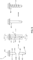
- a welding method 3 for manufacturing a bi-compositional screw 4B of a first preferred embodiment of this invention includes a preparing operation 31, a welding operation 32, and a forming operation 33.
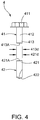
- the preparing operation 31 prepares two raw blanks 4 which are provided with different materials and processes the two raw blanks 4 respectively to form a front section 41 and a rear section 42, both of which are provided with smooth peripheral faces.
- the front section 41 has a head 411, a shank 412 extending outwards from the head 411, and a front end 413 with a front welding surface 413A formed on the front section 41 opposite to the head 411.
- the rear section 42 has a rear end 421 with a rear welding surface 421A formed on an end of the rear section 42 and a drill end 422 formed on another end of the rear section 42 opposite to the rear end 421.
- both of the front welding surface 413A and the rear welding surface 421A are formed in a flat surface.
- an outer diameter 413d of the front end 413 is equal to an outer diameter 421d of the rear end 421, thereby providing a smooth peripheral face of the bi-compositional blank 4A thereafter and an equal circumference (not shown) from the shank 412 to the rear end 421.
- the front section 41 can be made of a corrosion-resisting material such as stainless steel.
- the rear section 42 can be made of a material with higher hardness such as martensite or hardened materials.
- the welding operation 32 prepares a welding device 5 and a positioning device 6 disposed below the welding device 5, then position the front section 41 and the rear section 42 on the positioning device 6 to allow the front welding surface 413A and the rear welding surface 421A to contact closely along an axis R and meet at a joint C2, and thence rotates the front section 41 and the rear section 42 in the same rotational direction driven by the positioning device 6 and simultaneously welds the front end 413 and the rear end 421 at the joint C2 in a circumferential direction executed by the welding device 5 which is disposed above the joint C2 where the front end 413 and the rear end 421 meet, thereby integrating the front section 41 and the rear section 42 to provide a bi-compositional blank 4A.
- the welding operation 32 of this invention is executed by direct heating without applying additional solder, the welding operation 32 can prevent air and pores from generating inside the joint C2 and prevents waste from being projected out of the joint C2 effectively. Thus, no additional trimming procedure is required in the welding method 3 before executing the forming operation 33.
- the forming operation 33 rolls a plurality of threads 41 on the bi-compositional blank 4A via a threading machine (not shown) to form a bi-compositional screw 4B.
- the drill end 422 can be processed into a drilling tail via a tail forming machine (not shown) according to needs.
- a succession of the operations 31, 32, 33 including the preparing, welding and forming attains the quick and smooth manufacturing operation of the bi-compositional screw 4B, simplifies the processing procedures effectively, reduces the processing costs, and ensures the preferable processing quality.
- the welding method of this invention includes the preparing operation, the welding operation and the forming operation.
- the preparing operation prepares and processes two raw blanks provided with different materials into the front section and rear section respectively.
- the welding operation circumferentially welds the front and rear sections which are placed in the same axis at the joint by the welding device during the rotation of the front and rear sections in the same rotational direction driven by the positioning device, thereby combining the front and rear sections into the bi-compositional blank.
- the forming operation forms a plurality of threads on the bi-compositional blank to produce the bi-compositional screw, thereby preventing the generation of air and pores inside the joint, avoiding causing additional waste extruded out of the joint, simplifying the processing procedures, reducing the processing costs, and ensuring the preferable processing quality.
Landscapes
- Engineering & Computer Science (AREA)
- Mechanical Engineering (AREA)
- Physics & Mathematics (AREA)
- General Engineering & Computer Science (AREA)
- Optics & Photonics (AREA)
- Plasma & Fusion (AREA)
- Geometry (AREA)
- Chemical & Material Sciences (AREA)
- Materials Engineering (AREA)
- Butt Welding And Welding Of Specific Article (AREA)
Priority Applications (1)
| Application Number | Priority Date | Filing Date | Title |
|---|---|---|---|
| EP18248141.6A EP3674028A1 (de) | 2018-12-28 | 2018-12-28 | Schweissverfahren zur herstellung einer schraube aus zwei verschiedenen materialien |
Applications Claiming Priority (1)
| Application Number | Priority Date | Filing Date | Title |
|---|---|---|---|
| EP18248141.6A EP3674028A1 (de) | 2018-12-28 | 2018-12-28 | Schweissverfahren zur herstellung einer schraube aus zwei verschiedenen materialien |
Publications (1)
| Publication Number | Publication Date |
|---|---|
| EP3674028A1 true EP3674028A1 (de) | 2020-07-01 |
Family
ID=65011797
Family Applications (1)
| Application Number | Title | Priority Date | Filing Date |
|---|---|---|---|
| EP18248141.6A Withdrawn EP3674028A1 (de) | 2018-12-28 | 2018-12-28 | Schweissverfahren zur herstellung einer schraube aus zwei verschiedenen materialien |
Country Status (1)
| Country | Link |
|---|---|
| EP (1) | EP3674028A1 (de) |
Cited By (3)
| Publication number | Priority date | Publication date | Assignee | Title |
|---|---|---|---|---|
| DE102021112643A1 (de) | 2021-05-17 | 2022-11-17 | Fischerwerke Gmbh & Co. Kg | Verfahren zur Herstellung einer Bimetallschraube, Grundkörper einer Bimetallschraube, sowie Bimetallschraube |
| WO2023285166A1 (de) | 2021-07-14 | 2023-01-19 | Fischerwerke Gmbh & Co. Kg | Verfahren zur herstellung einer bimetallschraube und entsprechend hergestellte bimetallschraube |
| EP4336057A1 (de) | 2022-09-12 | 2024-03-13 | fischerwerke GmbH & Co. KG | Verfahren zur herstellung einer bimetallschraube, grundkörper einer bimetallschraube, sowie bimetallschraube |
Citations (6)
| Publication number | Priority date | Publication date | Assignee | Title |
|---|---|---|---|---|
| TW201115038A (en) * | 2009-10-28 | 2011-05-01 | Shehkai Prec Co Ltd | Method for manufacturing composite screw |
| US20160184930A1 (en) * | 2014-01-15 | 2016-06-30 | Ihi Corporation | Method of welding shaft and wheel in turbine shaft, turbine shaft, and welding device |
| US20170120369A1 (en) * | 2014-06-18 | 2017-05-04 | Ntn Corporation | Method for butt welding, butt welded joint, and outside joint member for constant velocity universal joint |
| JP6144323B2 (ja) * | 2015-11-30 | 2017-06-07 | 平田ネジ株式会社 | バイメタルねじの製造方法 |
| EP3267052A1 (de) * | 2016-07-08 | 2018-01-10 | HILTI Aktiengesellschaft | Schraube und herstellungsverfahren |
| CN109986225A (zh) * | 2018-12-24 | 2019-07-09 | 庆达科技股份有限公司 | 复合螺丝的焊接方法 |
-
2018
- 2018-12-28 EP EP18248141.6A patent/EP3674028A1/de not_active Withdrawn
Patent Citations (6)
| Publication number | Priority date | Publication date | Assignee | Title |
|---|---|---|---|---|
| TW201115038A (en) * | 2009-10-28 | 2011-05-01 | Shehkai Prec Co Ltd | Method for manufacturing composite screw |
| US20160184930A1 (en) * | 2014-01-15 | 2016-06-30 | Ihi Corporation | Method of welding shaft and wheel in turbine shaft, turbine shaft, and welding device |
| US20170120369A1 (en) * | 2014-06-18 | 2017-05-04 | Ntn Corporation | Method for butt welding, butt welded joint, and outside joint member for constant velocity universal joint |
| JP6144323B2 (ja) * | 2015-11-30 | 2017-06-07 | 平田ネジ株式会社 | バイメタルねじの製造方法 |
| EP3267052A1 (de) * | 2016-07-08 | 2018-01-10 | HILTI Aktiengesellschaft | Schraube und herstellungsverfahren |
| CN109986225A (zh) * | 2018-12-24 | 2019-07-09 | 庆达科技股份有限公司 | 复合螺丝的焊接方法 |
Cited By (5)
| Publication number | Priority date | Publication date | Assignee | Title |
|---|---|---|---|---|
| DE102021112643A1 (de) | 2021-05-17 | 2022-11-17 | Fischerwerke Gmbh & Co. Kg | Verfahren zur Herstellung einer Bimetallschraube, Grundkörper einer Bimetallschraube, sowie Bimetallschraube |
| WO2023285166A1 (de) | 2021-07-14 | 2023-01-19 | Fischerwerke Gmbh & Co. Kg | Verfahren zur herstellung einer bimetallschraube und entsprechend hergestellte bimetallschraube |
| DE102021118219A1 (de) | 2021-07-14 | 2023-01-19 | Fischerwerke Gmbh & Co. Kg | Bimetallschraube und Verfahren zur Herstellung der Bimetallschraube |
| EP4336057A1 (de) | 2022-09-12 | 2024-03-13 | fischerwerke GmbH & Co. KG | Verfahren zur herstellung einer bimetallschraube, grundkörper einer bimetallschraube, sowie bimetallschraube |
| DE102022123111A1 (de) | 2022-09-12 | 2024-03-14 | Fischerwerke Gmbh & Co. Kg | Verfahren zur Herstellung einer Bimetallschraube, Grundkörper einer Bimetallschraube, sowie Bimetallschraube |
Similar Documents
| Publication | Publication Date | Title |
|---|---|---|
| EP3674028A1 (de) | Schweissverfahren zur herstellung einer schraube aus zwei verschiedenen materialien | |
| EP2987583B1 (de) | Rotationsreibschweissen für rohrförmige werkstücke | |
| JP2821553B2 (ja) | 管状加工物を連続的にかつ切削屑無しに個々のリングに分離する方法及び装置 | |
| US20070172325A1 (en) | Forstner drill bit | |
| CN104722910A (zh) | 一种能减小变形去除飞边的搅拌摩擦连接装置 | |
| JP6833710B2 (ja) | 工作機械及び工作機械による加工方法 | |
| US10507533B2 (en) | Drill | |
| CN113226620A (zh) | 摩擦搅拌焊接中提高焊针速度及稳定性的装置及方法 | |
| CN110524105B (zh) | 一种用于摩擦焊的旋转焊具及焊接方法 | |
| US20200206848A1 (en) | Welding method for manufacturing a bi-compositional screw | |
| CN110860783B (zh) | 提升搅拌摩擦焊接设备主轴轴向承载能力装置 | |
| JP6320855B2 (ja) | 等速自在継手の外側継手部材の製造方法および外側継手部材 | |
| US11498159B2 (en) | Welding mechanism for manufacturing a bi-compositional screw | |
| CN109312771A (zh) | 螺钉和制造方法 | |
| RU2247639C1 (ru) | Способ сварки трением стыковых соединений из алюминиевых сплавов | |
| CN111716078A (zh) | 一种用于薄壁圆筒状钢壳体直缝的等离子焊接方法 | |
| CN109986225B (zh) | 复合螺丝的焊接方法 | |
| TWI716785B (zh) | 複合螺絲之焊接方法 | |
| JP2012240115A (ja) | 回転摩擦圧接方法および接合体 | |
| JP2005095954A (ja) | 回転軸の製造方法 | |
| RU2404885C1 (ru) | Способ заварки отверстия торца трубы | |
| US4989377A (en) | Apparatus for internal grinding | |
| US10968738B1 (en) | Remanufactured conical bit | |
| WO2017113040A1 (zh) | 金属冷热切圆锯片及其制造工艺 | |
| JP6848737B2 (ja) | 歯型ロールの製造方法及び鋼板の加工方法 |
Legal Events
| Date | Code | Title | Description |
|---|---|---|---|
| PUAI | Public reference made under article 153(3) epc to a published international application that has entered the european phase |
Free format text: ORIGINAL CODE: 0009012 |
|
| STAA | Information on the status of an ep patent application or granted ep patent |
Free format text: STATUS: THE APPLICATION HAS BEEN PUBLISHED |
|
| AK | Designated contracting states |
Kind code of ref document: A1 Designated state(s): AL AT BE BG CH CY CZ DE DK EE ES FI FR GB GR HR HU IE IS IT LI LT LU LV MC MK MT NL NO PL PT RO RS SE SI SK SM TR |
|
| AX | Request for extension of the european patent |
Extension state: BA ME |
|
| STAA | Information on the status of an ep patent application or granted ep patent |
Free format text: STATUS: REQUEST FOR EXAMINATION WAS MADE |
|
| 17P | Request for examination filed |
Effective date: 20201019 |
|
| RBV | Designated contracting states (corrected) |
Designated state(s): AL AT BE BG CH CY CZ DE DK EE ES FI FR GB GR HR HU IE IS IT LI LT LU LV MC MK MT NL NO PL PT RO RS SE SI SK SM TR |
|
| STAA | Information on the status of an ep patent application or granted ep patent |
Free format text: STATUS: EXAMINATION IS IN PROGRESS |
|
| 17Q | First examination report despatched |
Effective date: 20220728 |
|
| STAA | Information on the status of an ep patent application or granted ep patent |
Free format text: STATUS: THE APPLICATION IS DEEMED TO BE WITHDRAWN |
|
| 18D | Application deemed to be withdrawn |
Effective date: 20240511 |