EP3674033A1 - Procédé de détermination de la topographie d'une machine à outils - Google Patents
Procédé de détermination de la topographie d'une machine à outils Download PDFInfo
- Publication number
- EP3674033A1 EP3674033A1 EP19214318.8A EP19214318A EP3674033A1 EP 3674033 A1 EP3674033 A1 EP 3674033A1 EP 19214318 A EP19214318 A EP 19214318A EP 3674033 A1 EP3674033 A1 EP 3674033A1
- Authority
- EP
- European Patent Office
- Prior art keywords
- axis
- component
- data processing
- processing device
- data
- Prior art date
- Legal status (The legal status is an assumption and is not a legal conclusion. Google has not performed a legal analysis and makes no representation as to the accuracy of the status listed.)
- Granted
Links
Images

Classifications
-
- B—PERFORMING OPERATIONS; TRANSPORTING
- B23—MACHINE TOOLS; METAL-WORKING NOT OTHERWISE PROVIDED FOR
- B23Q—DETAILS, COMPONENTS, OR ACCESSORIES FOR MACHINE TOOLS, e.g. ARRANGEMENTS FOR COPYING OR CONTROLLING; MACHINE TOOLS IN GENERAL CHARACTERISED BY THE CONSTRUCTION OF PARTICULAR DETAILS OR COMPONENTS; COMBINATIONS OR ASSOCIATIONS OF METAL-WORKING MACHINES, NOT DIRECTED TO A PARTICULAR RESULT
- B23Q17/00—Arrangements for observing, indicating or measuring on machine tools
- B23Q17/22—Arrangements for observing, indicating or measuring on machine tools for indicating or measuring existing or desired position of tool or work
-
- G—PHYSICS
- G01—MEASURING; TESTING
- G01B—MEASURING LENGTH, THICKNESS OR SIMILAR LINEAR DIMENSIONS; MEASURING ANGLES; MEASURING AREAS; MEASURING IRREGULARITIES OF SURFACES OR CONTOURS
- G01B21/00—Measuring arrangements or details thereof, where the measuring technique is not covered by the other groups of this subclass, unspecified or not relevant
- G01B21/02—Measuring arrangements or details thereof, where the measuring technique is not covered by the other groups of this subclass, unspecified or not relevant for measuring length, width, or thickness
- G01B21/04—Measuring arrangements or details thereof, where the measuring technique is not covered by the other groups of this subclass, unspecified or not relevant for measuring length, width, or thickness by measuring coordinates of points
- G01B21/042—Calibration or calibration artifacts
Definitions
- the invention relates to a method by means of which a topography of a machine tool can be determined, in particular as part of a calibration of the machine tool.
- Modern machine tools especially the so-called machining centers, combine high flexibility in machining operations with high machining accuracy.
- To achieve this high level of machining accuracy it is necessary for a machine tool to be measured as precisely as possible before it is put into operation and to be calibrated on the basis of the data determined in this way.
- this calibration it is also necessary for this calibration to be repeated at regular intervals and if necessary, for example after an unforeseen operating state of the machine tool.
- the calibration of the machine tool is essentially carried out manually by expert persons on the basis of measurement instructions and measurement protocols. It is particularly disadvantageous here that this type of calibration is time-consuming and that even with highly qualified specialist personnel it can never be completely avoided that measured values are recorded incorrectly and / or inaccurately and / or transmitted.
- One object of an embodiment of the invention is to provide a method by means of which the determination of the topography can be simplified and carried out more precisely.
- step a takes place manually or semi-automatically.
- the method can be further simplified if the determination and / or detection in step a is also carried out by means of the or another automated or automatable measuring device which is connected or can be connected to the data processing device in a data and / or signal-conducting manner.
- the determination and detection according to step a can include, in particular, the determination and detection of an inclination of the machine bed by means of an inclination measuring device.
- the inclinometer can be placed, for example, on an alignment surface of the machine bed which, when the machine bed is correctly aligned, is oriented perpendicular to a gravity acting in the location of the alignment surface.
- an inclination angle of the tool holder is determined during its movement along the axes of the coordinate system. If the angle of inclination of the tool holder remains constant during the process, the linear guides are straight. If the angle of inclination of the tool carrier changes, then the linear guides have rounded, in particular curved, or angled sections.
- the orientation of the component carrier in relation to the coordinate system of the machine tool is determined in step c by means of a measuring device that can be positioned on the machine bed as a function of the coordinate system, for example by means of a laser range finder.
- a further step takes place, namely: d.
- step d On the basis of the data determined in steps a to c, it is possible in step d to easily determine whether the linear guides are arranged at right angles to one another.
- a measuring angle can be arranged on the component holder, which can be felt by the probe held by the tool holder.
- the measuring angle has tactile surfaces which can be aligned parallel to three spatial planes spanned by the first axis, the second axis and the third axis.
- the measuring angle is aligned in such a way that one of the touch surfaces is aligned parallel to the spatial plane formed by the second and third axes. Then be Tactile points along a spatial line aligned parallel to the third axis are determined. Then touch points are determined along a spatial line aligned parallel to the second axis. From the spatial lines that can be determined by the probe and, in particular, data from a machine control, it can be determined whether the linear guides assigned to the second axis and the third axis are arranged at right angles to one another.
- a sensing surface of the measuring angle is at least almost aligned parallel to the spatial plane formed by the first and second or by the first and third axes. Then touch points are determined along a spatial line aligned parallel to the second or third axis. Then touch points are determined along the spatial line aligned parallel to the first axis. From the spatial lines that can be determined by the measuring probe and, in particular, data from a machine control, it can be determined whether the linear guides assigned to the first axis and the second or third axis are arranged at least almost at right angles to one another.
- a further step takes place, namely: e. Determination and detection of an offset of the tool holder in the direction of the first axis and / or the third axis by means of the or another automated or automatable measuring device which is connected or can be connected to the data processing device in a data and / or signal-conducting manner.
- step e determines whether the tool holder has an offset in the direction of the first axis and / or the third axis.
- a touch surface is or can be arranged on the component receptacle, which can be aligned perpendicular to the first or third axis and parallel to the second axis. It is advantageously provided that a plurality of touch points spaced apart from one another in the direction of the second axis and arranged on the touch surface are approached with the touch probe. In this way, the offset of the tool holder in the direction of the first or third axis can be determined.
- a straightness of the touch surface is also checked, for example to determine wear, damage or the like on the component holder and / or the component carrier can. It is particularly advantageous here if the tactile surface is designed as a section of the component receptacle.
- a further step can take place, namely: f. Determination and detection of an offset of the tool holder in the direction of the second axis by means of the or another automated or automatable measuring device which is connected or can be connected to the data processing device in a data and / or signal-conducting manner.
- the component receptacle particularly preferably has a recess with a known position and a known shape, for example a bore.
- the recess is advantageously approached with the probe in such a way that its position in the coordinate system is determined. Out The determined values of the positions of the recesses can be used to determine whether the tool holder has a shelf along the second axis.
- a further step follows after one of steps a, b, c, d, e and / or f, namely: G. Determination and detection of the concentricity of the tool holder and an angle difference between a tool axis and the first axis by means of the or another automated or automatable measuring device which is connected and / or connectable to the data processing device in a data and / or signal-conducting manner.
- this step of the method it is determined in particular whether a concentricity of a tool arranged in the tool holder around the tool axis and whether there is an angular difference between the tool axis and the first axis within a specified tolerance.
- a measuring mandrel is arranged in the tool holder, which has a cylindrically designed sensing surface arranged parallel to the first axis, a measuring probe being arranged in the component holder.
- the tool holder with the measuring mandrel arranged in it is rotated step by step around the first axis, the measuring mandrel being scanned by means of the measuring probe arranged in the component holder after each rotation step. From the tactile points determined in this way, an ideal concentricity of the measuring mandrel can be determined.
- the tool holder with the measuring mandrel arranged in it is moved step by step along the first axis, the measuring mandrel being scanned by means of the measuring probe arranged in the component holder after each moving step. From that An angular difference between the tool axis and the first axis can be determined.
- this step of the method it is determined in particular whether the tool holder is arranged at right angles to the second axis and the third axis.
- a measuring tool is arranged in the tool holder, which has a scanning surface aligned parallel to the second and third axes, a measuring probe being arranged in the component holder.
- the tool holder with the measuring tool arranged in it rotates step by step around the first axis and is positioned over the second and third axes, after each Rotation step a touch point arranged on the touch surface is felt with the probe. From the data determined in this way, a circular path / arc can be determined, along which the touch point moves and on the basis of which it can be determined whether the tool holder is arranged at right angles to the second and third axes.
- a further step namely: i. Determining and detecting an angular difference between a carrier rotation axis of the component carrier and the first axis and / or the carrier rotation axis and the third axis by means of the or another automated or automatable measuring device which is connected or can be connected to the data processing device in a data and / or signal-conducting manner.
- a probe can be arranged in the tool holder, a kinematic measuring device, which in particular has a spherical probe body, being arranged on a first rotational section of the component carrier, through which the component holder is held and which can be rotated around the axis of rotation of the carrier.
- the first rotation section of the component carrier is rotated step by step around the carrier axis of rotation, with the component carrier being moved along the corresponding linear axes after each rotation step in such a way that the probe is directed toward a normal of a surface of the probe body when the probe body is touched. From the data determined in this way, a circular path / arc can be determined, along which the touch point moves and on the basis of which an angle difference between the carrier rotation axis and the first and / or second axis can be determined.
- the method can be applied to a machine tool, the component carrier of which has a second rotation section which lies opposite the first rotation section.
- the component holder is held, guided and driven by both rotation sections.
- step i the step: j1.
- Determining and detecting a parallelism of the component carrier in relation to the second axis and / or the third axis by means of the or another automated or automatable measuring device which is connected or can be connected to the data processing device in a data and / or signal-conducting manner, takes place and that the machine tool comprises a 3-axis machine tool, on the component holder of which a component can be secured against rotation.
- step j1 it is provided that a parallelism of the component holder to the second axis and to the third axis is checked.
- a measuring probe is arranged in the tool holder, with which flat surfaces of the component holder, which can be aligned parallel to the second and / or third axis, are scanned. From this it can be determined whether the component holder can actually be aligned parallel to these axes.
- Kinematics of the first axis of rotation is understood below and refers to rotations of elements of the machine tool about the auxiliary axes related to the component carrier, which correspond to the carrier rotation axis and the auxiliary axis parallel to it.
- step j2 it is provided that the position of the axis of rotation is checked and whether the carrier axis of rotation is actually arranged at right angles to the corresponding linear axes. In addition, it is checked in step j2 whether the auxiliary axis parallel to the carrier rotation axis is oriented perpendicular to the corresponding linear axes.
- the kinematic measuring device is fixed on the component holder, a measuring probe being arranged in the tool holder.
- the component carrier is rotated step by step around the carrier axis of rotation, with the component carrier being moved along the corresponding linear axes after each rotation step in such a way that the probe is directed toward a normal of the surface of the probe body when the probe body is felt. From the data determined in this way, a circular path / arc can be determined, along which the touch point moves.
- the perpendicularity of the carrier rotation axis with respect to the corresponding linear axes can be determined from an angular offset between the plane spanned by the circular path / arc and a plane spanned by a center point of the circular path / arc and the corresponding linear axes.
- the kinematic measuring device is fixed on the component holder, a measuring probe being arranged in the tool holder.
- the component carrier is moved step by step along the axis of rotation of the carrier, with the component carrier being moved along the corresponding linear axes after each travel step in such a way that the probe is felt when the Probe body is directed in the direction of a normal to the surface of the probe body extending through a probe point.
- a spatial line can be determined, along which the probe body is moved.
- a perpendicularity of the auxiliary axis parallel to the carrier rotation axis to the corresponding linear axes can be determined.
- step k1 it is provided that a parallelism of the component receptacle to the first, second and third axes is checked.
- a measuring probe is arranged in the tool holder, with which flat surfaces of the component holder, which can be aligned parallel to the first and / or second and / or third axis, are scanned. From this it can be determined whether the component holder can actually be aligned parallel to these axes.
- the component carrier with the component holder is rotated by 360 ° in a first direction around the carrier rotation axis for a first check of the parallelism of the component holder.
- the component carrier is then rotated through 360 ° in a second direction around the axis of rotation of the carrier and a second check of the parallelism is carried out. This enables reversal errors when rotating about the carrier rotation axis to be determined.
- step j3 similar to step j2, it is provided to check the position of the carrier rotation axis and whether the carrier rotation axis is actually arranged at right angles to the corresponding linear axes.
- step j3 also in analogy to step j2, it is checked whether the auxiliary axis parallel to the axis of rotation of the carrier is oriented perpendicular to the corresponding linear axes.
- the kinematic measuring device is fixed on the rotary section of the component holder, the probe being arranged in the tool holder.
- the position and perpendicularity of the Carrier rotation axis with respect to the corresponding linear axes analog to step j2.
- the kinematics measuring device is fixed to the rotary section of the component holder, a measuring probe being arranged in the tool holder is.
- the determination of the position of the auxiliary axis parallel to the carrier rotation axis and the perpendicularity between the auxiliary axis parallel to the carrier rotation axis and the corresponding linear axes is further carried out in analogy to the method used in the 4-axis machine tool and described in step j2.
- Kinematics of the second axis of rotation is used below to refer to and understand a rotation of elements of the machine tool around the auxiliary axes related to the rotary section of the component carrier, which correspond to the component rotary axis of the rotary section and the auxiliary axis parallel to it.
- step k2 the position of the component rotation axis is checked and whether the component rotation axis is arranged at right angles to the corresponding linear axes.
- step k2 the position of the auxiliary axis parallel to the component rotation axis is checked in step k2 and whether this auxiliary axis is aligned perpendicular to the corresponding linear axes.
- the kinematic measuring device is fixed to the rotary section of the component holder, a measuring probe being arranged in the tool holder.
- the rotary section is rotated step by step around the axis of rotation of the component, with the component carrier being moved after each rotation step in such a way that the probe is directed towards a normal of the surface of the probe body when the probe body is felt. From the data determined in this way, a circular path / arc can be determined, along which the touch point moves.
- the perpendicularity of the carrier rotation axis with respect to the corresponding linear axes can be determined from an angular offset between the plane spanned by the circular path / arc and a plane spanned by a center point of the circular path / arc and the corresponding linear axes.
- the kinematic measuring device is fixed to the rotary section of the component holder, a measuring probe being arranged in the tool holder.
- the component carrier is moved step by step along the component rotation axis, the rotary section always having the same angle of rotation with respect to the component receptacle, and after each travel step the component carrier or tool carrier is moved in such a way that the measuring probe, when the probe body is felt, in the direction of a normal to the surface running through a probe point the probe body is directed.
- a distance can be determined on the basis of the known machine parameters, along which the probe body is moved.
- a perpendicularity of the auxiliary axis parallel to the component rotation axis to the corresponding linear axes can be determined.
- step I touch points are recorded step by step on the rotary section by means of a measuring probe arranged in the tool holder.
- the turning section is rotated by 180 ° around the component rotation axis and measured again in a second pass.
- a circular path along which the touch point moves can be determined from the data determined in this way.
- the circular path of the touch point of the rotary section is preferably determined in three positions of the component carrier. In a 0 ° position in which the component rotation axis is aligned parallel to the first axis and perpendicular to the second and third axes, and in a 90 ° position and in a -90 ° position.
- the positions are also particularly preferred Measurements carried out after the positions of the component carrier were approached in different directions.
- step I From the circular orbits determined in step I, the flatness of the rotary section, an oblique position of the component rotation axis and the position of the carrier rotation axis and their reversal errors can be determined.
- first and a second measuring recess are approached by means of a probe arranged in the tool holder.
- the first measuring recess is preferably a centering hole in the rotating section through which the component rotation axis runs and the second measuring recess is a device receiving hole for aligning a device on the rotating section.
- the data processing device creates a topography report of the machine tool on the basis of the data determined and recorded in steps a to i and j1 or a to i and j2 to k1 or a to i and j3 to m becomes.
- the machine tool can, for example, be calibrated on the basis of the topography protocol.
- topography reports can be created as part of regular maintenance work, which can be compared, for example, in order to determine changes in the machine tool.
- partial topography protocols can be created that take into account only a part of steps a to i and j1 or a to i as well as j2 to k1 or a to i and j3 to m.
- the data processing device determines correction values on the basis of at least one rule stored in the data processing device, by means of which the topography of the machine tool can be adjusted.
- the accuracy of the machine tool can be improved by adjusting the machine tool on the basis of the correction values.
- the data processing device and / or a further data processing device creates an acceptance report of the machine tool on the basis of the topography report and / or the correction values.
- the machine tool is started up for the first time, it is common for important parameters of the machine tool to be recorded. For example, it is common for settings that are made to calibrate the machine tool to be documented.
- the topography of the machine tool is mechanically adjusted on the basis of the topography protocol and / or the correction values.
- Mechanical adjustment in the sense of the concept of the invention means both the setting of the machine by means of adjusting elements provided for this purpose and the reworking of the machine, for example by means of cold forming by means of chisels, hammers, hydraulic presses or the like.
- the topography protocol and / or the correction values are transmitted from the data processing device to a control device of the machine tool, which controls the machine tool on the basis of the topography protocol and / or the correction values.
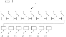
- FIG. 1 A method 1 for determining a topography of a machine tool is shown.
- the machine tool has a machine bed, by means of which a Cartesian coordinate system of the machine tool starting from a machine zero point is defined, a tool carrier which can be displaced along linear guides which are aligned parallel to axes of the coordinate system, and which has at least one tool holder for receiving a cutting tool and one Component carrier, which is spaced from the tool carrier in the direction of a first axis and which comprises a component receptacle oriented parallel to the first axis and through which a component to be machined can be held.
- step a 2 of method 1 the orientation of the machine bed is determined and recorded.
- the straightness of the linear guides is then determined and recorded in step b 3.
- the orientation of the component carrier in relation to the coordinate system is then determined and recorded in step c4.
- the determination in steps b 3 and c 4 takes place by means of automated measuring devices which are connected in a data-conducting manner to a data processing device.
- step d 5 takes place, in which the arrangement of the linear guides relative to one another is determined and recorded by means of an automated measuring device which is connected in a signal-conducting manner to the data processing device.
- step e 6 takes place in which an offset of the tool holder in the direction of the first axis and the third axis is determined and by means of an automated measuring device which is connected in a signal-conducting manner to the data processing device is recorded.
- step f 7 takes place, in which an offset of the tool holder in the direction of the second axis is determined and recorded by means of an automated measuring device which is connected to the data processing device in a data-conducting manner becomes.
- step g 8 takes place, in which there is an angle difference between a tool axis and the first axis and the concentricity of the tool holder by means of an automated measuring device, which carries the data the data processing device is connected, determined and recorded.
- step h 9 takes place in which an angle difference between the tool axis and the second axis and the tool axis and the third axis is achieved by means of an automated one Measuring device, which is connected to the data processing device in a data-conducting manner, is determined and recorded.
- step i 10 takes place in which there is an angular difference between a carrier rotation axis of the component carrier and the first axis and the carrier rotation axis and third axis is determined and recorded by means of an automated measuring device, which is connected to the data processing device in a data-conducting manner.
- step j1 the parallelism of the component carrier in relation to the second axis and / or the third axis is determined and recorded by means of an automated measuring device which is connected to the data processing device in a data-conducting manner.
- the method 1 shown is preferably applied to a 3-axis machine tool, on the component receptacle of which a component can be secured against rotation.
- steps j2 12 and k1 13 kinematics of the first axis of rotation of the component carrier as it rotates about the carrier axis of rotation is determined and recorded by means of an automated measuring device which is connected to the data processing device in a data-conducting manner.
- step k1 13 a parallelism of the component carrier in relation to the first axis and / or the second axis and / or the third axis is determined and recorded by means of an automated measuring device which is connected to the data processing device in a data-conducting manner.
- Method 1 shown is preferably applied to a 4-axis machine tool, on the component receptacle of which a component can be secured against rotation.
- step j3 14 kinematics of the first axis of rotation of the component carrier are rotated by means of a when rotating about the carrier axis of rotation automated measuring device, which is connected to the data processing device in a data-conducting manner, is determined and recorded.
- step k2 15 a kinematics of the second axis of rotation of the rotary section of the component holder as it rotates about the component axis of rotation is determined and recorded by means of an automated measuring device which is connected to the data processing device in a data-conducting manner.
- step I 16 a flatness of the rotary section of the component holder is determined and recorded by means of an automated measuring device which is connected to the data processing device in a data-conducting manner.
- step m 17 a concentricity of the rotary section of the component holder in relation to the tool holder is determined and recorded by means of an automated measuring device which is connected to the data processing device in a data-conducting manner.
- the illustrated method 1 takes place after step j1 11 or step k1 13 or step m 17, on the basis of the data determined and recorded in the respectively preceding steps, a topography creation step 18 in which a topography protocol of the machine tool is created.
- the method 1 shown takes place after each individual determination step as well as after the entire topography creation step 18 by the data processing device on the basis of the topography protocol and rules stored in the data processing device, a correction determination step 19 in which correction values are determined, on the basis of which the topography of the machine tool can be adjusted.
- the adjustment is carried out both mechanically and in terms of control technology.
- the illustrated method 1 takes place after the topography creation step 18 and the correction determination step 19 by the data processing device on the basis of the topography protocol, a final protocol step 20 in which an acceptance protocol of the machine tool is created.
Landscapes
- Engineering & Computer Science (AREA)
- Mechanical Engineering (AREA)
- Physics & Mathematics (AREA)
- General Physics & Mathematics (AREA)
- Length Measuring Devices With Unspecified Measuring Means (AREA)
- Automatic Control Of Machine Tools (AREA)
Applications Claiming Priority (2)
| Application Number | Priority Date | Filing Date | Title |
|---|---|---|---|
| DE102018133628 | 2018-12-27 | ||
| DE102019104604.1A DE102019104604A1 (de) | 2018-12-27 | 2019-02-22 | Verfahren zum Bestimmen einer Topographie einer Werkzeugmaschine |
Publications (3)
| Publication Number | Publication Date |
|---|---|
| EP3674033A1 true EP3674033A1 (fr) | 2020-07-01 |
| EP3674033C0 EP3674033C0 (fr) | 2023-07-12 |
| EP3674033B1 EP3674033B1 (fr) | 2023-07-12 |
Family
ID=68835057
Family Applications (1)
| Application Number | Title | Priority Date | Filing Date |
|---|---|---|---|
| EP19214318.8A Active EP3674033B1 (fr) | 2018-12-27 | 2019-12-07 | Procédé de détermination de la topographie d'une machine à outils |
Country Status (1)
| Country | Link |
|---|---|
| EP (1) | EP3674033B1 (fr) |
Citations (6)
| Publication number | Priority date | Publication date | Assignee | Title |
|---|---|---|---|---|
| JPH04122534A (ja) * | 1990-09-14 | 1992-04-23 | Hitachi Seiko Ltd | 工作機械におけるベッドの捩じれ補正装置 |
| US20100060906A1 (en) * | 2008-09-08 | 2010-03-11 | Wen-Yuh Jywe | Means for Measuring a Working Machine's Structural Deviation from Five Reference Axes |
| JP2014151423A (ja) * | 2013-02-13 | 2014-08-25 | Makino Milling Mach Co Ltd | 工作機械のレベル調整方法及び装置 |
| DE102015219141A1 (de) * | 2015-10-02 | 2017-04-06 | Deckel Maho Seebach Gmbh | Verfahren und Vorrichtung zur Vermessung einer numerisch gesteuerten Werkzeugmaschine |
| EP3255515A2 (fr) * | 2016-06-09 | 2017-12-13 | STEGER, Heinrich | Procédé de fonctionnement d'une machine à commande numérique |
| DE102016226073A1 (de) * | 2016-12-22 | 2018-06-28 | Deckel Maho Pfronten Gmbh | Vorrichtung zum einsatz in einer numerisch gesteuerten werkzeugmaschine zur verwendung in einem verfahren zum vermessen der numerisch gesteuerten werkzeugmaschine |
Family Cites Families (1)
| Publication number | Priority date | Publication date | Assignee | Title |
|---|---|---|---|---|
| JP2004345005A (ja) * | 2003-05-20 | 2004-12-09 | Toyota Motor Corp | 工作機械のレベリングボルト調整量算出装置、工作機械及び工作機械群のレベル監視方法 |
-
2019
- 2019-12-07 EP EP19214318.8A patent/EP3674033B1/fr active Active
Patent Citations (6)
| Publication number | Priority date | Publication date | Assignee | Title |
|---|---|---|---|---|
| JPH04122534A (ja) * | 1990-09-14 | 1992-04-23 | Hitachi Seiko Ltd | 工作機械におけるベッドの捩じれ補正装置 |
| US20100060906A1 (en) * | 2008-09-08 | 2010-03-11 | Wen-Yuh Jywe | Means for Measuring a Working Machine's Structural Deviation from Five Reference Axes |
| JP2014151423A (ja) * | 2013-02-13 | 2014-08-25 | Makino Milling Mach Co Ltd | 工作機械のレベル調整方法及び装置 |
| DE102015219141A1 (de) * | 2015-10-02 | 2017-04-06 | Deckel Maho Seebach Gmbh | Verfahren und Vorrichtung zur Vermessung einer numerisch gesteuerten Werkzeugmaschine |
| EP3255515A2 (fr) * | 2016-06-09 | 2017-12-13 | STEGER, Heinrich | Procédé de fonctionnement d'une machine à commande numérique |
| DE102016226073A1 (de) * | 2016-12-22 | 2018-06-28 | Deckel Maho Pfronten Gmbh | Vorrichtung zum einsatz in einer numerisch gesteuerten werkzeugmaschine zur verwendung in einem verfahren zum vermessen der numerisch gesteuerten werkzeugmaschine |
Also Published As
| Publication number | Publication date |
|---|---|
| EP3674033C0 (fr) | 2023-07-12 |
| EP3674033B1 (fr) | 2023-07-12 |
Similar Documents
| Publication | Publication Date | Title |
|---|---|---|
| EP3456453B1 (fr) | Procédé et dispositif de taillage | |
| EP1696289B1 (fr) | Procédé pour dimensionner une machine-outil | |
| EP1663573B1 (fr) | Affuteuse presentant un systeme de correction de concentricite | |
| DE102012110673B4 (de) | Werkzeugmaschine und Verfahren zur Vermessung eines Werkstücks | |
| DE112014003036B4 (de) | Bodenfräsmaschine | |
| WO2019115332A1 (fr) | Procédé et dispositif servant à mesurer un outil d'usinage par laminage | |
| EP4093571A1 (fr) | Procédé pour usiner une pièce présentant deux dentures, dispositif de positionnement pour déterminer une position d'angle de rotation de référence de la pièce et machine-outil équipée d'un tel dispositif de positionnement | |
| EP2835702B1 (fr) | Procédé de mesure d'au moins un axe rotatif d'une machine-outil | |
| EP3453487A1 (fr) | Procédé de positionnement d'un point central sur un axe géométrique dans une machine-outil | |
| DE102012201732B4 (de) | Numerisch gesteuerte Werkzeugmaschine und Verfahren zum Steuern eines automatischen rotatorischen Ausrichtvorgangs eines Zahnrads an der Werkzeugmaschine | |
| EP0729005B1 (fr) | Dispositif de mesure pour la vérification de la précision géométrique et dynamique des machines-outil NC et des robots industriels | |
| EP4034347B1 (fr) | Procédé de précision d'une position et / ou d'une orientation d'une tête d'appareil | |
| EP1366394A2 (fr) | Procede et dispositif pour la mesure et l'usinage de pieces | |
| EP2282244A1 (fr) | Procédé de traitement de pièces usinées | |
| DE102019104604A1 (de) | Verfahren zum Bestimmen einer Topographie einer Werkzeugmaschine | |
| EP3781919B1 (fr) | Procédé de détermination de la masse et du centre de gravité d'une charge utile d'un système de déplacement, en particulier dans une machine-outil | |
| DE3320983A1 (de) | Transportables geraet zur pruefung des zahnflankenprofils und der zahnflankenlinien (zahnschraege) von zahnraedern auf verzahnmaschinen oder zahnflankenschleifmaschinen sowie zur positionierung dieses geraetes und zum orientieren des messtasters an der verzahnung fuer den messvorgang | |
| DE102018101407B4 (de) | Werkzeugmaschine und Verfahren zur Vorbereitung einer Bearbeitung eines spanabtragenden Rotationswerkzeugs | |
| EP4034348B1 (fr) | Procédé de précision d'une position et / ou d'une orientation d'une tête d'appareil | |
| DE102019104420A1 (de) | Anordnung und Verfahren zur Justage eines Roboterarms | |
| DE10304430B3 (de) | Verfahren zum Kalibrieren einer Schleifmaschine | |
| EP3674033B1 (fr) | Procédé de détermination de la topographie d'une machine à outils | |
| EP4286094B1 (fr) | Procédé et dispositif d'usinage pour l'affûtage de lames d'un outil de coupe rotatif | |
| EP2080584A1 (fr) | Dispositif et procédé destinés au traitement de pièces à usiner | |
| DE102016221458A1 (de) | Verbesserte Bearbeitungsvorrichtung und entsprechendes Betriebsverfahren |
Legal Events
| Date | Code | Title | Description |
|---|---|---|---|
| PUAI | Public reference made under article 153(3) epc to a published international application that has entered the european phase |
Free format text: ORIGINAL CODE: 0009012 |
|
| STAA | Information on the status of an ep patent application or granted ep patent |
Free format text: STATUS: REQUEST FOR EXAMINATION WAS MADE |
|
| STAA | Information on the status of an ep patent application or granted ep patent |
Free format text: STATUS: EXAMINATION IS IN PROGRESS |
|
| 17P | Request for examination filed |
Effective date: 20191209 |
|
| AK | Designated contracting states |
Kind code of ref document: A1 Designated state(s): AL AT BE BG CH CY CZ DE DK EE ES FI FR GB GR HR HU IE IS IT LI LT LU LV MC MK MT NL NO PL PT RO RS SE SI SK SM TR |
|
| AX | Request for extension of the european patent |
Extension state: BA ME |
|
| 17Q | First examination report despatched |
Effective date: 20200629 |
|
| RBV | Designated contracting states (corrected) |
Designated state(s): AL AT BE BG CH CY CZ DE DK EE ES FI FR GB GR HR HU IE IS IT LI LT LU LV MC MK MT NL NO PL PT RO RS SE SI SK SM TR |
|
| GRAP | Despatch of communication of intention to grant a patent |
Free format text: ORIGINAL CODE: EPIDOSNIGR1 |
|
| STAA | Information on the status of an ep patent application or granted ep patent |
Free format text: STATUS: GRANT OF PATENT IS INTENDED |
|
| INTG | Intention to grant announced |
Effective date: 20230322 |
|
| GRAS | Grant fee paid |
Free format text: ORIGINAL CODE: EPIDOSNIGR3 |
|
| GRAA | (expected) grant |
Free format text: ORIGINAL CODE: 0009210 |
|
| STAA | Information on the status of an ep patent application or granted ep patent |
Free format text: STATUS: THE PATENT HAS BEEN GRANTED |
|
| AK | Designated contracting states |
Kind code of ref document: B1 Designated state(s): AL AT BE BG CH CY CZ DE DK EE ES FI FR GB GR HR HU IE IS IT LI LT LU LV MC MK MT NL NO PL PT RO RS SE SI SK SM TR |
|
| REG | Reference to a national code |
Ref country code: CH Ref legal event code: EP |
|
| REG | Reference to a national code |
Ref country code: IE Ref legal event code: FG4D Free format text: LANGUAGE OF EP DOCUMENT: GERMAN |
|
| REG | Reference to a national code |
Ref country code: DE Ref legal event code: R096 Ref document number: 502019008479 Country of ref document: DE |
|
| U01 | Request for unitary effect filed |
Effective date: 20230724 |
|
| U07 | Unitary effect registered |
Designated state(s): AT BE BG DE DK EE FI FR IT LT LU LV MT NL PT SE SI Effective date: 20230727 |
|
| REG | Reference to a national code |
Ref country code: LT Ref legal event code: MG9D |
|
| PG25 | Lapsed in a contracting state [announced via postgrant information from national office to epo] |
Ref country code: GR Free format text: LAPSE BECAUSE OF FAILURE TO SUBMIT A TRANSLATION OF THE DESCRIPTION OR TO PAY THE FEE WITHIN THE PRESCRIBED TIME-LIMIT Effective date: 20231013 |
|
| PG25 | Lapsed in a contracting state [announced via postgrant information from national office to epo] |
Ref country code: ES Free format text: LAPSE BECAUSE OF FAILURE TO SUBMIT A TRANSLATION OF THE DESCRIPTION OR TO PAY THE FEE WITHIN THE PRESCRIBED TIME-LIMIT Effective date: 20230712 |
|
| PG25 | Lapsed in a contracting state [announced via postgrant information from national office to epo] |
Ref country code: IS Free format text: LAPSE BECAUSE OF FAILURE TO SUBMIT A TRANSLATION OF THE DESCRIPTION OR TO PAY THE FEE WITHIN THE PRESCRIBED TIME-LIMIT Effective date: 20231112 |
|
| PG25 | Lapsed in a contracting state [announced via postgrant information from national office to epo] |
Ref country code: RS Free format text: LAPSE BECAUSE OF FAILURE TO SUBMIT A TRANSLATION OF THE DESCRIPTION OR TO PAY THE FEE WITHIN THE PRESCRIBED TIME-LIMIT Effective date: 20230712 Ref country code: NO Free format text: LAPSE BECAUSE OF FAILURE TO SUBMIT A TRANSLATION OF THE DESCRIPTION OR TO PAY THE FEE WITHIN THE PRESCRIBED TIME-LIMIT Effective date: 20231012 Ref country code: IS Free format text: LAPSE BECAUSE OF FAILURE TO SUBMIT A TRANSLATION OF THE DESCRIPTION OR TO PAY THE FEE WITHIN THE PRESCRIBED TIME-LIMIT Effective date: 20231112 Ref country code: HR Free format text: LAPSE BECAUSE OF FAILURE TO SUBMIT A TRANSLATION OF THE DESCRIPTION OR TO PAY THE FEE WITHIN THE PRESCRIBED TIME-LIMIT Effective date: 20230712 Ref country code: GR Free format text: LAPSE BECAUSE OF FAILURE TO SUBMIT A TRANSLATION OF THE DESCRIPTION OR TO PAY THE FEE WITHIN THE PRESCRIBED TIME-LIMIT Effective date: 20231013 Ref country code: ES Free format text: LAPSE BECAUSE OF FAILURE TO SUBMIT A TRANSLATION OF THE DESCRIPTION OR TO PAY THE FEE WITHIN THE PRESCRIBED TIME-LIMIT Effective date: 20230712 |
|
| U20 | Renewal fee for the european patent with unitary effect paid |
Year of fee payment: 5 Effective date: 20240102 |
|
| PG25 | Lapsed in a contracting state [announced via postgrant information from national office to epo] |
Ref country code: PL Free format text: LAPSE BECAUSE OF FAILURE TO SUBMIT A TRANSLATION OF THE DESCRIPTION OR TO PAY THE FEE WITHIN THE PRESCRIBED TIME-LIMIT Effective date: 20230712 |
|
| REG | Reference to a national code |
Ref country code: DE Ref legal event code: R097 Ref document number: 502019008479 Country of ref document: DE |
|
| PG25 | Lapsed in a contracting state [announced via postgrant information from national office to epo] |
Ref country code: SM Free format text: LAPSE BECAUSE OF FAILURE TO SUBMIT A TRANSLATION OF THE DESCRIPTION OR TO PAY THE FEE WITHIN THE PRESCRIBED TIME-LIMIT Effective date: 20230712 Ref country code: RO Free format text: LAPSE BECAUSE OF FAILURE TO SUBMIT A TRANSLATION OF THE DESCRIPTION OR TO PAY THE FEE WITHIN THE PRESCRIBED TIME-LIMIT Effective date: 20230712 Ref country code: CZ Free format text: LAPSE BECAUSE OF FAILURE TO SUBMIT A TRANSLATION OF THE DESCRIPTION OR TO PAY THE FEE WITHIN THE PRESCRIBED TIME-LIMIT Effective date: 20230712 Ref country code: SK Free format text: LAPSE BECAUSE OF FAILURE TO SUBMIT A TRANSLATION OF THE DESCRIPTION OR TO PAY THE FEE WITHIN THE PRESCRIBED TIME-LIMIT Effective date: 20230712 |
|
| PLBE | No opposition filed within time limit |
Free format text: ORIGINAL CODE: 0009261 |
|
| STAA | Information on the status of an ep patent application or granted ep patent |
Free format text: STATUS: NO OPPOSITION FILED WITHIN TIME LIMIT |
|
| 26N | No opposition filed |
Effective date: 20240415 |
|
| REG | Reference to a national code |
Ref country code: CH Ref legal event code: PL |
|
| PG25 | Lapsed in a contracting state [announced via postgrant information from national office to epo] |
Ref country code: MC Free format text: LAPSE BECAUSE OF FAILURE TO SUBMIT A TRANSLATION OF THE DESCRIPTION OR TO PAY THE FEE WITHIN THE PRESCRIBED TIME-LIMIT Effective date: 20230712 |
|
| GBPC | Gb: european patent ceased through non-payment of renewal fee |
Effective date: 20231207 |
|
| PG25 | Lapsed in a contracting state [announced via postgrant information from national office to epo] |
Ref country code: MC Free format text: LAPSE BECAUSE OF FAILURE TO SUBMIT A TRANSLATION OF THE DESCRIPTION OR TO PAY THE FEE WITHIN THE PRESCRIBED TIME-LIMIT Effective date: 20230712 |
|
| REG | Reference to a national code |
Ref country code: IE Ref legal event code: MM4A |
|
| PG25 | Lapsed in a contracting state [announced via postgrant information from national office to epo] |
Ref country code: IE Free format text: LAPSE BECAUSE OF NON-PAYMENT OF DUE FEES Effective date: 20231207 |
|
| PG25 | Lapsed in a contracting state [announced via postgrant information from national office to epo] |
Ref country code: GB Free format text: LAPSE BECAUSE OF NON-PAYMENT OF DUE FEES Effective date: 20231207 |
|
| PG25 | Lapsed in a contracting state [announced via postgrant information from national office to epo] |
Ref country code: CH Free format text: LAPSE BECAUSE OF NON-PAYMENT OF DUE FEES Effective date: 20231231 |
|
| PG25 | Lapsed in a contracting state [announced via postgrant information from national office to epo] |
Ref country code: IE Free format text: LAPSE BECAUSE OF NON-PAYMENT OF DUE FEES Effective date: 20231207 Ref country code: GB Free format text: LAPSE BECAUSE OF NON-PAYMENT OF DUE FEES Effective date: 20231207 Ref country code: CH Free format text: LAPSE BECAUSE OF NON-PAYMENT OF DUE FEES Effective date: 20231231 |
|
| U20 | Renewal fee for the european patent with unitary effect paid |
Year of fee payment: 6 Effective date: 20250102 |
|
| PG25 | Lapsed in a contracting state [announced via postgrant information from national office to epo] |
Ref country code: CY Free format text: LAPSE BECAUSE OF FAILURE TO SUBMIT A TRANSLATION OF THE DESCRIPTION OR TO PAY THE FEE WITHIN THE PRESCRIBED TIME-LIMIT; INVALID AB INITIO Effective date: 20191207 |
|
| PG25 | Lapsed in a contracting state [announced via postgrant information from national office to epo] |
Ref country code: HU Free format text: LAPSE BECAUSE OF FAILURE TO SUBMIT A TRANSLATION OF THE DESCRIPTION OR TO PAY THE FEE WITHIN THE PRESCRIBED TIME-LIMIT; INVALID AB INITIO Effective date: 20191207 |
|
| PG25 | Lapsed in a contracting state [announced via postgrant information from national office to epo] |
Ref country code: TR Free format text: LAPSE BECAUSE OF FAILURE TO SUBMIT A TRANSLATION OF THE DESCRIPTION OR TO PAY THE FEE WITHIN THE PRESCRIBED TIME-LIMIT Effective date: 20230712 |
|
| U20 | Renewal fee for the european patent with unitary effect paid |
Year of fee payment: 7 Effective date: 20260102 |