EP3674039A1 - Vorrichtung, verfahren und system zum lehren eines roboters - Google Patents
Vorrichtung, verfahren und system zum lehren eines roboters Download PDFInfo
- Publication number
- EP3674039A1 EP3674039A1 EP17922778.0A EP17922778A EP3674039A1 EP 3674039 A1 EP3674039 A1 EP 3674039A1 EP 17922778 A EP17922778 A EP 17922778A EP 3674039 A1 EP3674039 A1 EP 3674039A1
- Authority
- EP
- European Patent Office
- Prior art keywords
- joints
- robot
- teaching
- angles
- user
- Prior art date
- Legal status (The legal status is an assumption and is not a legal conclusion. Google has not performed a legal analysis and makes no representation as to the accuracy of the status listed.)
- Withdrawn
Links
Images



Classifications
-
- B—PERFORMING OPERATIONS; TRANSPORTING
- B25—HAND TOOLS; PORTABLE POWER-DRIVEN TOOLS; MANIPULATORS
- B25J—MANIPULATORS; CHAMBERS PROVIDED WITH MANIPULATION DEVICES
- B25J9/00—Program-controlled manipulators
- B25J9/0081—Program-controlled manipulators with leader teach-in means
-
- B—PERFORMING OPERATIONS; TRANSPORTING
- B25—HAND TOOLS; PORTABLE POWER-DRIVEN TOOLS; MANIPULATORS
- B25J—MANIPULATORS; CHAMBERS PROVIDED WITH MANIPULATION DEVICES
- B25J9/00—Program-controlled manipulators
- B25J9/16—Program controls
- B25J9/1628—Program controls characterised by the control loop
- B25J9/163—Program controls characterised by the control loop learning, adaptive, model based, rule based expert control
-
- B—PERFORMING OPERATIONS; TRANSPORTING
- B25—HAND TOOLS; PORTABLE POWER-DRIVEN TOOLS; MANIPULATORS
- B25J—MANIPULATORS; CHAMBERS PROVIDED WITH MANIPULATION DEVICES
- B25J18/00—Arms
- B25J18/02—Arms extensible
- B25J18/04—Arms extensible rotatable
-
- B—PERFORMING OPERATIONS; TRANSPORTING
- B25—HAND TOOLS; PORTABLE POWER-DRIVEN TOOLS; MANIPULATORS
- B25J—MANIPULATORS; CHAMBERS PROVIDED WITH MANIPULATION DEVICES
- B25J9/00—Program-controlled manipulators
- B25J9/02—Program-controlled manipulators characterised by movement of the arms, e.g. cartesian coordinate type
- B25J9/04—Program-controlled manipulators characterised by movement of the arms, e.g. cartesian coordinate type by rotating at least one arm, excluding the head movement itself, e.g. cylindrical coordinate type or polar coordinate type
- B25J9/041—Cylindrical coordinate type
- B25J9/042—Cylindrical coordinate type comprising an articulated arm
-
- B—PERFORMING OPERATIONS; TRANSPORTING
- B25—HAND TOOLS; PORTABLE POWER-DRIVEN TOOLS; MANIPULATORS
- B25J—MANIPULATORS; CHAMBERS PROVIDED WITH MANIPULATION DEVICES
- B25J9/00—Program-controlled manipulators
- B25J9/10—Program-controlled manipulators characterised by positioning means for manipulator elements
- B25J9/106—Program-controlled manipulators characterised by positioning means for manipulator elements with articulated links
-
- B—PERFORMING OPERATIONS; TRANSPORTING
- B25—HAND TOOLS; PORTABLE POWER-DRIVEN TOOLS; MANIPULATORS
- B25J—MANIPULATORS; CHAMBERS PROVIDED WITH MANIPULATION DEVICES
- B25J9/00—Program-controlled manipulators
- B25J9/16—Program controls
- B25J9/1628—Program controls characterised by the control loop
- B25J9/1643—Program controls characterised by the control loop redundant control
-
- B—PERFORMING OPERATIONS; TRANSPORTING
- B25—HAND TOOLS; PORTABLE POWER-DRIVEN TOOLS; MANIPULATORS
- B25J—MANIPULATORS; CHAMBERS PROVIDED WITH MANIPULATION DEVICES
- B25J9/00—Program-controlled manipulators
- B25J9/16—Program controls
- B25J9/1656—Program controls characterised by programming, planning systems for manipulators
- B25J9/1664—Program controls characterised by programming, planning systems for manipulators characterised by motion, path, trajectory planning
-
- G—PHYSICS
- G05—CONTROLLING; REGULATING
- G05B—CONTROL OR REGULATING SYSTEMS IN GENERAL; FUNCTIONAL ELEMENTS OF SUCH SYSTEMS; MONITORING OR TESTING ARRANGEMENTS FOR SUCH SYSTEMS OR ELEMENTS
- G05B19/00—Program-control systems
- G05B19/02—Program-control systems electric
- G05B19/42—Recording and playback systems, i.e. in which the program is recorded from a cycle of operations, e.g. the cycle of operations being manually controlled, after which this record is played back on the same machine
- G05B19/423—Teaching successive positions by walk-through, i.e. the tool head or end effector being grasped and guided directly, with or without servo-assistance, to follow a path
Definitions
- Embodiments of the present disclosure relate to a device, method, and system for teaching a robot.
- Robots play important roles as tools for performing various tasks on behalf of humans.
- Robots may automatically perform a variety of tasks such as supplying, assembling, welding, and painting on production lines of manufactories in a similar manner to human arms, but with improved productivity
- the present disclosure provides a method, device, and system of teaching a robot to maintain constant a direction in which an end of the robot faces during teaching.
- the present disclosure provides a method, device, and system for teaching a robot which may enable an end of the robot to more easily satisfy a certain requirement according to the teaching of a user.
- the present disclosure provides a method, device, and system for teaching a robot which may use some joints to maintain constant a direction in which an end of the robot faces, in a general articulated robot.
- a method of teaching a robot capable of maintaining constant a direction in which an end faces and including N joints (N is a natural number) includes: obtaining a reference direction in which the end is to face; calculating angles of M joints (M is a natural number, and N>M) from among the N joints to correspond to teaching of a user with respect to the robot; and calculating angles of remaining joints so that the end faces in the reference direction, based on the angles of the M joints.
- the remaining joints may be joints other than the M joints from among the N joints.
- the teaching may be performed by a physical manipulation of the user with respect to the robot, wherein the calculating of the angles of the M joints includes driving the M joints to correspond to the angles of the M joints according to the physical manipulation of the user with respect to the robot.
- the teaching may be performed by a control signal for at least one of the M joints, and the control signal may be generated by a manipulation of an input unit by the user, wherein the calculating of the angles of the M joints includes driving at least one of the M joints according to the control signal for the at least one of the M joints.
- the calculating of the angles of the remaining joints may include driving the remaining joints based on the calculated angles of the remaining joints.
- the remaining joints may be joints continuous and closest to the end from among the N joints.
- N may be 6, and M may be 3.
- the reference direction may be a direction perpendicular to a working plane of the robot.
- a device for teaching a robot capable of maintaining constant a direction in which an end faces and including N joints (N is a natural number) includes a controller, wherein the controller is configured to: obtain a reference direction in which the end is to face; calculate angles of M joints (M is a natural number, and N>M) from among the N joints to correspond to teaching of a user with respect to the robot; and calculate angles of remaining joints so that the end faces in the reference direction, based on the angles of the M joints.
- the remaining joints may be joints other than the M joints from among the N joints
- the teaching may be performed by a physical manipulation of the user with respect to the robot, wherein the controller is further configured to drive the M joints to correspond to the angles of the M joints according to the physical manipulation of the user with respect to the robot.
- the teaching may be performed by a control signal for at least one of the M joints, and the control signal may be generated by a manipulation of an input unit by the user, wherein the controller is further configured to drive at least one of the M joints according to the control signal for the at least one of the M joints.
- the controller may be further configured to drive the remaining joints based on the calculated angles of the remaining joints.
- the remaining joints may be joints continuous and closest to the end from among the N joints.
- N may be 6, and M may be 3.
- the reference direction may be a direction perpendicular to a working plane of the robot.
- a system for teaching a robot to maintain constant a direction in which an end of the robot faces during teaching includes: the robot including N joints (N is a natural number); and a robot teaching device configured to control the robot to maintain constant the direction in which the end of the robot faces.
- the robot teaching device may be further configured to obtain a reference direction in which the end of the robot is to face, calculate angles of M joints (M is a natural number, and N>M) from among the N joints to correspond to teaching of a user with respect to the robot, and calculate angles of remaining joints so that the end faces in the reference direction, based on the angles of the M joints, In this case, the remaining joints may be joints other than the M joints from among the N joints.
- the teaching may be performed by a physical manipulation of the user with respect to the robot, wherein the robot teaching device is further configured to drive the M joints to correspond to the angles of the M joints according to the physical manipulation of the user with respect to the robot.
- the teaching may be performed by a control signal for at least one of the M joints, and the control signal may be generated by a manipulation of an input unit by the robot teaching device of the user, wherein the robot teaching device is further configured to drive at least one of the M joints according to the control signal for the at least one of the M joints.
- the robot teaching device may be further configured to drive the remaining joints based on the calculated angles of the remaining joints.
- the remaining joints may be joints continuous and closest to the end from among the N joints.
- a method, device, and system for teaching a robot which may maintain constant a direction in which an end of the robot faces during teaching may be realized.
- a method, device, and system for teaching a robot which may enable an end of the robot to more easily satisfy a certain requirement according to the teaching of a user may be realized.
- a method, device, and system for teaching a robot which may use some joints to maintain constant a direction in which an end of the robot faces, in a general articulated robot.
- a method of teaching a robot capable of maintaining constant a direction in which an end faces and including N joints (N is a natural number) includes: obtaining a reference direction in which the end is to face; calculating angles of M joints (M is a natural number, and N>M) from among the N joints to correspond to teaching of a user with respect to the robot; and calculating angles of remaining joints so that the end faces in the reference direction, based on the angles of the M joints.
- the remaining joints may be joints other than the M joints from among the N joints.
- Embodiments of the present disclosure may be described in terms of functional block components and various processing steps. Such functional blocks may be realized by any number of hardware and/or software components configured to perform specific functions. For example, embodiments of the present disclosure may employ various integrated circuit (IC) components, e.g., memory elements, processing elements, logic elements, look-up tables, and the like, which may carry out a variety of functions under the control of one or more microprocessors or other control devices. Similarly, where the elements of the present disclosure are implemented using software programming or software elements, the present disclosure may be implemented with any programming or scripting language such as C, C++, Java, assembler language, or the like, with the various algorithms being implemented with any combination of data structures, objects, processes, routines or other programming elements.
- IC integrated circuit
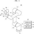
- FIG. 1 illustrates a robot system according to an embodiment of the present disclosure.
- the robot system may include a robot teaching device 100 and a robot 200.
- the robot system according to an embodiment of the present disclosure may maintain constant a direction in which an end of the robot 200 faces, despite the teaching of a user with respect to the robot 200.
- 'teaching' used herein may refer to a process of allowing the user to manipulate the robot 200 so that the robot 200 takes a specific posture.
- the term 'manipulation' may refer to a process of allowing the user to apply a physical force to the robot 200 so that the robot 200 takes a specific posture.
- some joints (e.g., 211 through 213) of the robot 200 may be appropriately set to have a resistance force enough to be rotatable by the user.
- a rotating torque for maintaining a posture of a joint may be set to an intensity such that a rotation angle is changeable by the user.
- the term 'manipulation' may refer to a process of allowing the user to manipulate an input unit of the robot 200 so that a control signal is generated and the robot 200 takes a specific posture according to the control signal.
- a manipulation of the user may refer to a process of inputting angles of some joints (e.g., 211 through 213) or inputting positions of some parts (e.g., 221 through 223).
- a manipulation of the user may refer to a process of dragging or clicking on a shape of the robot 200 displayed on a display 120.
- this is merely an example, and the spirit of the present disclosure is not limited thereto.
- the term 'posture' of the robot 200 used herein may refer to a specific state of the robot 200 in a three-dimensional (3D) space.
- a 'posture' of the robot 200 may refer to at least one from among a rotation angle of each joint, a position of each part in a 3D space, and a driving condition of an actuator constituting each joint when the robot 200 is in a specific state.
- the robot 200 may be a device including one or more actuators and one or more parts.
- the term 'actuator' may refer to any of various devices for converting electrical energy into kinetic energy based on a control signal.
- the actuator may be any one of a direct current (DC) servomotor, an alternating current (AC) servomotor, a stepping motor, a linear motor, a hydraulic cylinder, a hydraulic motor, a pneumatic cylinder, and a pneumatic motor.
- DC direct current
- AC alternating current
- stepping motor a linear motor
- hydraulic cylinder hydraulic motor
- pneumatic cylinder pneumatic motor
- the term 'part' may refer to a structure for fixing the actuator at a specific position or a structure fixed to the actuator to be movable.
- the robot 200 may be any one of, for example, an articulated robot, a selective compliance assembly robot arm (SCARA) robot, and a cylindrical robot.
- the articulated robot may be a robot having one or more joints and parts (or bodies) for connecting different joints.
- the SCARA robot may be a robot including an arm that operates in a specific plane.
- the cylindrical robot may be a robot including an arm that has at least one rotary joint and at least one prismatic joint.
- any device including one or more actuators and one or more parts and operating according to a control signal may be the robot 200 according to the present disclosure.
- the robot 200 is an articulated robot having N joints and parts for connecting the joints as shown in FIG. 1 .
- the robot 200 includes six joints 211, 212, 213, 214, 215, and 216 and six parts 221, 222, 223, 224, 225, and 226, and each of the six joints 211, 212, 213, 214, 215, and 216 includes an angle measuring means for measuring a rotation angle of a joint.
- the part 221 from among the six parts 221, 222, 223, 224, 225, and 226 of the robot 200 is fixed to the ground.
- the robot teaching device 100 may include a controller 110, the display 120, and an input unit 130.
- the controller 110 may drive some joints according to the teaching of the user, and may drive remaining joints according to a certain condition.
- the controller 110 may include any type of device capable of processing data such as a processor.
- the term 'processor' may refer to a data processing device embedded in hardware and having physical circuitry to carry out code or instructions of a program. Examples of the data processing device embedded in the hardware may include, but are not limited to, a microprocessor, a central processing unit (CPU), a processor core, a multiprocessor, an application-specific integrated circuit (ASIC), and a field programmable gate array.
- the display 120 may display a current operation state of the robot 200.
- the display 20 may refer to a display device for displaying figures, letters, or images.
- the display 120 may include any one from among, but not limited to, a cathode ray tube (CRT), a liquid crystal display (LCD), a plasma display panel (PDP), a light-emitting diode (LED), and an organic light-emitting diode (OLED).
- CTR cathode ray tube
- LCD liquid crystal display
- PDP plasma display panel
- LED light-emitting diode
- OLED organic light-emitting diode
- the input unit 130 may refer to any of various means for obtaining an input of the user.
- the input unit 130 may be a keyboard, a mouse, a trackball, a microphone, a button, or a combination thereof.
- the input unit 130 may refer to, but is not limited to, a touch unit for inputting a touch to the display 120.
- this is merely an example, and the spirit of the present disclosure is not limited thereto.
- the robot teaching device 100 may further include a communicator (not shown) and a memory (not shown).
- the communicator may be a device including hardware and software needed to transmit/receive a control signal through wired/wireless connection between the robot teaching device 100 and an external device such as the robot 200.
- the memory (not shown) temporarily or permanently stores data processed by the robot teaching device 100.
- the memory may include, but is not limited to, a magnetic storage medium or a flash storage medium.
- the robot teaching device 100 may be separated from the robot 200 and/or a robot control device (not shown) as shown in FIG. 1 .
- the robot teaching device 100 may be included in the robot 200 and/or the robot control device (not shown).
- the robot 200 and/or the robot control device (not shown) may perform a method of teaching a robot according to an embodiment of the present disclosure.
- the controller 110 of the robot teaching device 100 may control the robot 200 to maintain constant a direction in which an end of the robot 200 faces during a teaching process.
- the term 'end' of the robot 200 used herein may refer to a part closest to a target object of a task of the robot 200.
- the part 226 may become an end of the robot 200.
- the part 226 and the end are used interchangeably.
- the controller 110 may obtain a reference direction 310 in which the end 226 of the robot 200 is to face.
- the term 'reference direction 310' used herein may refer to a direction in which the end 226 of the robot 200 is to face, despite a change in a posture of the robot 200 according to teaching.
- the reference direction may be a direction perpendicular to a working plane in a 3D space, or a southward direction.
- the reference direction 310 may be obtained by using the teaching of the user with respect to the reference direction 310.
- the user may set the reference direction 310 by physically manipulating each part of the robot 200 including the end 226 so that the end 226 of the robot 200 faces in the reference direction 310 that is to be set by the user.
- the reference direction 310 may be obtained when the user manipulates the input unit 130.
- the user may generate a control signal for at least one joint of the robot 200 through the input unit 130, and may set the reference direction 310 by transmitting the control signal to each of the joints 211 through 216.
- this is merely an example, and the spirit of the present disclosure is not limited thereto.
- the controller 110 may calculate angles of M joints from among the N joints of the robot 200 to correspond to the teaching of the user with respect to the robot 200. Also, the controller 110 may drive the M joints to correspond to the angles of the M joints calculated by the above process. In this case, M may be a natural number less than N that is the number of joints of the robot 200.
- 'a joint When 'a joint is driven to correspond to an angle', it may mean that the joint is rotated to correspond to the angle. For example, assuming that an angle of the joint 211 before teaching is 0° and an angle calculated according to the teaching is -30°, when the 'joint 211 is driven to correspond to -30°', it may mean that the controller 110 rotates the joint 211 in a negative direction by 30°.
- FIG. 2 is a view for describing a method performed by the controller 110 to control the robot 200 according to the teaching of a user according to an embodiment of the present disclosure.
- the controller 110 may calculate angles of three joints from among six joints to correspond to the teaching of the user as described above. Also, the controller 110 may drive the three joints to correspond to the calculated angles of the respective joints.
- the controller 110 may calculate angles of the joints 211 through 213 that are first through third joints to correspond to the teaching of the user.
- the controller 110 may calculate angles of only the first joint 211 and the second joint 212.
- the controller 110 may also calculate a rotation angle of the third joint 213 that is the same as a previous angle (because there is no change in the angle).
- the controller 110 may drive the first joint 211 and the second joint 212 to correspond to the calculated angles of the respective joints.
- the controller 110 may drive the third joint 213 to maintain its current angle.
- the controller 110 may calculate angles of remaining joints so that the end 226 faces in the reference direction 310, based on the angles of the M joints calculated by the above process.
- the controller 110 may calculate angles of the remaining joints 214, 215, and 216 so that the end 226 faces in the reference direction 310.
- the controller 110 may calculate the angles of the remaining joints 214, 215, and 216 according to various methods. For example, the controller 110 may calculate the angles of the remaining joints 214 through 216, based on the angles of the M joints 211 through 213 calculated by the above process and 3D modeling data of the robot 200 including information about the joints 211 through 216 and the parts 221 through 226 for connecting the joints 211 through 216 of the robot 200.
- this is merely an example, and the spirit of the present disclosure is not limited thereto.
- the controller 110 may drive the remaining joints 214 through 216 based on the calculated angles of the remaining joints 214 through 216.
- the end 226 may always face in a constant direction, despite the teaching or manipulation of the user.
- FIG. 3 is a view for describing a direction 310a of the end 226 after teaching of the robot 200 according to an embodiment of the present disclosure.
- the reference direction 310 is set to a direction perpendicular to the working plane 400 in a space
- the teaching of a user includes a manipulation of rotating the first joint 211 in the direction 330 and the second direction 212 in the direction 320 as shown in FIG. 2
- the controller 110 drives three joints 211, 212, and 213 according to the teaching.
- the controller 110 may calculate angles of the remaining joints 214, 215, and 216 so that the end 226 faces in the reference direction 310 according to the teaching of the user, and may operate the remaining joints 214, 215, and 216 according to the calculated angles. Accordingly, the direction 310a in which the end 226 faces may be the same as the reference direction 310 that is initially set and may be perpendicular to the working plane 400.
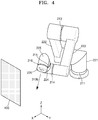
- FIG. 4 is a view for describing a direction 310b of the end 226 after teaching of the robot 200 according to the prior art.
- the reference direction 310 is set to a direction perpendicular to the working plane 400 in a space
- the teaching of a user includes a manipulation of rotating the first joint 211 in the direction 330 and the second joint 212 in the direction 320 as shown in FIG. 2
- the controller 110 drives three joints 211 through 213 according to the teaching.
- the direction 310b in which the end 226 faces may be different from the reference direction 310 that is initially set and may not be perpendicular to the working plane 400 as shown in FIG. 4 .
- the prior art has a problem in that the end 226 of the robot 200 is difficult to satisfy a certain requirement (e.g., a requirement for facing in a specific direction) according to the teaching of the user.
- a certain requirement e.g., a requirement for facing in a specific direction
- the prior art has a problem in that, although the teaching of the user with respect to all of the joints 211 through 216 is performed and the user manipulates a direction in which the end 226 faces to a direction perpendicular to the working plane 400, it may be difficult to determine whether the manipulated direction is accurately perpendicular to the working plane 400 and the direction in which the end 226 faces may be easily changed when angles of some joints are corrected.
- the present disclosure may solve the problems by controlling teaching to be performed on some joints of the articulated robot and controlling remaining joints to satisfy a certain requirement.
- joints on which teaching may be performed may be at least one.
- Joints that operate to satisfy a certain requirement may be at least three, and may be joints continuous and closest to an end from among a plurality of joints.
- a tool according to the purpose and/or use of the robot 200 may be attached to the end 226 of the robot 200 according to an embodiment of the present disclosure.
- the tool attached to the end 226 may be an image acquisition device for obtaining an image of a target object.
- the robot 200 may be used for the purpose of obtaining an image in order to check an assembly state of the target object.
- the above-described method may be used for calibration of the robot 200.
- an operation error or the like of the robot 200 may be checked by locating the end of the robot 200 at a plurality of points on a board for calibration and then checking an angle of each joint at each point.
- this is merely an example, and the spirit of the present disclosure is not limited thereto.
- FIG. 5 is a flowchart for describing a method of teaching a robot performed by the robot teaching device 100 of FIG. 1 . The same description as that made with reference to FIGS. 1 through 4 will not be provided here.
- the robot teaching device 100 may obtain the reference direction 310 in which the end 226 of the robot 200 is to face (S51).
- the term 'reference direction 310' used herein may refer to a direction in which the end 226 of the robot 200 is to face, despite a change in a posture of the robot 200 according to teaching.
- the reference direction may be a direction perpendicular to a working plane in a 3D space, or a southward direction.
- the reference direction 310 may be obtained by using the teaching of a user with respect to the reference direction 310.
- the user may set the reference direction 310 by physically manipulating each part of the robot 200 including the end 226 so that the end 226 of the robot 200 faces in the reference direction 310 that is to be set by the user.
- the reference direction 310 may be obtained when the user manipulates the input unit 130.
- the user may generate a control signal for at least one joint of the robot 200 through the input unit 130, and may set the reference direction 310 by transmitting the control signal to each of the joints 211 through 216.
- this is merely an example, and the spirit of the present disclosure is not limited thereto.
- the robot teaching device 100 may calculate angles of M joints from among N joints of the robot 200 to correspond to the teaching of the user with respect to the robot 200(S52). Also, the robot teaching device 100 may drive the M joints to correspond to the angles of the M joints calculated by the above process.
- M may be a natural number less than N that is the number of joints of the robot 200.
- a 'joint When a 'joint is driven to correspond to an angle', it may mean that the joint is rotated to correspond to the angle. For example, assuming that an angle of the joint 211 before teaching is 0° and an angle calculated according to teaching is -30°, when the 'joint 211 is driven to correspond to -30°', it may mean that the robot teaching device 100 rotates the joint 211 in a negative direction by 30°.
- the robot teaching device 100 may calculate angles of three joints from among six joints to correspond to the teaching of the user as described above. Also, the robot teaching device 100 may drive the three joints to correspond to the calculated angles of the respective joints.
- the robot teaching device 100 may calculate angles of the first through third joints 211 through 213 to correspond to the teaching of the user. In this case, because the teaching of the user includes only a manipulation for the first joint 211 and the second joint 212 according to the above assumption, the robot teaching device 100 may calculate angles of only the first joint 211 and the second joint 212. The robot teaching device 100 may also calculate a rotation angle of the third joint 213 that is the same as a previous angle (because there is no change in the angle).
- the robot teaching device 100 may drive the first joint 211 and the second joint 212 to correspond to the calculated angles of the respective joints.
- the robot teaching device 100 may drive the third joint 213 to maintain its current angle.
- the robot teaching device 100 may calculate angles of remaining joints so that the end 226 faces in the reference direction 310, based on the angles of the M joints calculated by the above process (S53).
- the robot teaching device 100 may calculate angles of the remaining joints 214, 215, and 216 so that the end 226 faces in the reference direction 310.
- the robot teaching device 100 may calculate the angles of the remaining joints 214, 215, and 216 according to various methods.
- the controller 110 may calculate the angles of the remaining joints 214 through 216, based on the angles of the M joints 211 through 213 calculated by the above process and 3D modeling data of the robot 200 including information about the joints 211 through 216 and the parts 221 through 226 for connecting the joints 211 through 216 of the robot 200.
- this is merely an example, and the spirit of the present disclosure is not limited thereto.
- the robot teaching device 100 may drive the remaining joints based on the calculated angles of the remaining joints 214 through 216.
- the end 226 may always face in a constant direction, despite the teaching or manipulation of the user.
- the reference direction 310 is set to a direction perpendicular to the working plane 400 in a space
- the teaching of the user includes a manipulation of rotating the first joint 211 in the direction 330 and the second joint 212 in the direction 320 as shown in FIG. 2 .
- the robot teaching device 100 drives three joints 211, 212, and 213 according to the teaching.
- the robot teaching device 100 may calculate angles of the remaining joints 214, 215, and 216 so that the end 226 faces in the reference direction 310 according to the teaching of the user, and may operate the remaining joints 214, 215, and 216 according to the calculated angles. Accordingly, the direction 310a in which the end 226 faces may be the same as the reference direction 310 that is initially set and may be perpendicular to the working plane 400.
- FIG. 4 describes the direction 310b of the end 226 after teaching of the robot 200 according to the prior art.
- the reference direction 310 is set to a direction perpendicular to the working plane 400 in a space
- the teaching of the user includes a manipulation of rotating the first joint 211 in the direction 330 and the second joint 212 in the direction 320 as shown in FIG. 2 .
- the robot teaching device 100 drives three joints 211 through 213 according to the teaching.
- the direction 310b in which the end 226 faces may be different from the reference direction 310 that is initially set and may not be perpendicular to the working plane 400 as shown in FIG. 4 .
- the prior art has a problem in that the end 226 of the robot 200 is difficult to satisfy a certain requirement (e.g., a requirement for facing in a specific direction) according to the teaching of the user.
- a certain requirement e.g., a requirement for facing in a specific direction
- the prior art has a problem in that, although the teaching of the user with respect to all of the joints 211 through 216 is performed and the user manipulates a direction in which the end 226 faces to a direction perpendicular to the working plane 400, it may be difficult to determine whether the manipulated direction is accurately perpendicular to the working plane 400 and the direction in which the end 226 faces may be easily changed when angles of some joints are corrected.
- the present disclosure may solve the problems by controlling teaching to be performed on some joints of the articulated robot according to the present disclosure and controlling remaining joints to satisfy a certain requirement.
- joints on which teaching may be performed may be at least one.
- Joints that operate to satisfy a certain requirement may be at least three, and may be joints continuous and closest to an end from among a plurality of joints.
- a tool according to the purpose and/or use of the robot 200 may be attached to the end 226 of the robot 200 according to an embodiment of the present disclosure.
- the tool attached to the end 226 may be an image acquisition device for obtaining an image of a target object.
- the robot 200 may be used for the purpose of obtaining an image in order to check an assembly state of the target object.
- the above-described method may be used for calibration of the robot 200.
- an operation error or the like of the robot 200 may be checked by locating the end of the robot 200 at a plurality of points on a board for calibration and then checking an angle of each joint at each point.
- this is merely an example, and the spirit of the present disclosure is not limited thereto.
- the present disclosure may be embodied as computer-readable code in a computer-readable recording medium.
- the computer-readable recording medium may be any recording apparatus capable of storing data that is read by a computer system. Examples of the computer-readable recording medium include read-only memories (ROMs), random-access memories (RAMs), compact disc (CD)-ROMs, magnetic tapes, floppy disks, and optical data storage devices. Also, the computer-readable medium may be distributed among computer systems that are interconnected through a network so that computer-readable code is stored and executed in a distributed fashion. Functional programs, code, and code segments for accomplishing the present disclosure may be easily derived by programmers in the art to which the present disclosure pertains.
Landscapes
- Engineering & Computer Science (AREA)
- Robotics (AREA)
- Mechanical Engineering (AREA)
- Physics & Mathematics (AREA)
- General Physics & Mathematics (AREA)
- Automation & Control Theory (AREA)
- Numerical Control (AREA)
- Manipulator (AREA)
Applications Claiming Priority (2)
| Application Number | Priority Date | Filing Date | Title |
|---|---|---|---|
| KR1020170105511A KR102474838B1 (ko) | 2017-08-21 | 2017-08-21 | 로봇의 교시 장치, 방법 및 시스템 |
| PCT/KR2017/012595 WO2019039654A1 (ko) | 2017-08-21 | 2017-11-08 | 로봇의 교시 장치, 방법 및 시스템 |
Publications (2)
| Publication Number | Publication Date |
|---|---|
| EP3674039A1 true EP3674039A1 (de) | 2020-07-01 |
| EP3674039A4 EP3674039A4 (de) | 2021-05-26 |
Family
ID=65438998
Family Applications (1)
| Application Number | Title | Priority Date | Filing Date |
|---|---|---|---|
| EP17922778.0A Withdrawn EP3674039A4 (de) | 2017-08-21 | 2017-11-08 | Vorrichtung, verfahren und system zum lehren eines roboters |
Country Status (5)
| Country | Link |
|---|---|
| US (1) | US20200189094A1 (de) |
| EP (1) | EP3674039A4 (de) |
| KR (1) | KR102474838B1 (de) |
| CN (1) | CN109699177A (de) |
| WO (1) | WO2019039654A1 (de) |
Families Citing this family (4)
| Publication number | Priority date | Publication date | Assignee | Title |
|---|---|---|---|---|
| CN114073585B (zh) * | 2020-08-19 | 2025-09-16 | 北京术锐机器人股份有限公司 | 机器人系统以及控制方法 |
| JP2023533919A (ja) | 2020-08-19 | 2023-08-07 | 北京術鋭機器人股▲ふん▼有限公司 | ロボットシステムおよび制御方法 |
| CN114073586B (zh) * | 2020-08-19 | 2025-09-16 | 北京术锐机器人股份有限公司 | 机器人系统以及控制方法 |
| CN112967559B (zh) * | 2021-03-29 | 2021-12-28 | 北京航空航天大学 | 一种基于虚拟装配环境的装配技能直接生成方法 |
Family Cites Families (14)
| Publication number | Priority date | Publication date | Assignee | Title |
|---|---|---|---|---|
| JPH05337860A (ja) * | 1992-06-05 | 1993-12-21 | Toyota Central Res & Dev Lab Inc | ロボットハンドの教示装置およびロボットハンド |
| EP0850730B1 (de) * | 1995-09-14 | 2002-07-24 | Kabushiki Kaisha Yaskawa Denki | Lehrvorrichtung für roboter |
| JP3633760B2 (ja) * | 1997-09-09 | 2005-03-30 | 日本電信電話株式会社 | ロボットマニピュレータの制御装置 |
| JP2000006067A (ja) * | 1998-06-23 | 2000-01-11 | Nippon Telegr & Teleph Corp <Ntt> | マニピュレータ用教示データ作成方法及び装置並びにプログラムを記録した記録媒体 |
| JP2000015593A (ja) * | 1998-06-30 | 2000-01-18 | Toshiba Corp | マニピュレータ軌道生成装置及びマニピュレータ軌道生成プログラムを記録した記録媒体 |
| US6385508B1 (en) * | 2000-10-31 | 2002-05-07 | Fanuc Robotics North America, Inc. | Lead-through teach handle assembly and method of teaching a robot assembly |
| WO2006086021A2 (en) * | 2004-10-25 | 2006-08-17 | University Of Dayton | Method and system to provide improved accuracies in multi-jointed robots through kinematic robot model parameters determination |
| JP2009050949A (ja) * | 2007-08-27 | 2009-03-12 | Ntn Corp | ロボットアームの軌道教示方法および軌道教示装置 |
| JP5338297B2 (ja) * | 2008-12-19 | 2013-11-13 | 株式会社安川電機 | ロボットの制御装置 |
| JP5701055B2 (ja) * | 2010-12-28 | 2015-04-15 | 川崎重工業株式会社 | 7軸多関節ロボットの制御方法、制御プログラム及びロボット制御装置 |
| CN102528802B (zh) * | 2010-12-31 | 2014-12-03 | 北京中科广视科技有限公司 | 九自由度机器人的运动驱动方法 |
| CN103492133B (zh) * | 2011-04-19 | 2016-04-13 | Abb研究有限公司 | 具有运动冗余臂的工业机器人和用于控制该机器人的方法 |
| KR101826577B1 (ko) * | 2012-12-12 | 2018-02-07 | 큐렉소 주식회사 | 로봇의 손목 축 움직임을 이용한 툴 보정 방법 |
| DE102013222456A1 (de) * | 2013-11-05 | 2015-05-07 | Kuka Laboratories Gmbh | Verfahren zum Programmieren von Bewegungsabläufen eines redundanten Industrieroboters und zugehöriger Industrieroboter |
-
2017
- 2017-08-21 KR KR1020170105511A patent/KR102474838B1/ko active Active
- 2017-11-08 EP EP17922778.0A patent/EP3674039A4/de not_active Withdrawn
- 2017-11-08 WO PCT/KR2017/012595 patent/WO2019039654A1/ko not_active Ceased
- 2017-11-08 CN CN201780001646.3A patent/CN109699177A/zh active Pending
-
2020
- 2020-02-21 US US16/797,151 patent/US20200189094A1/en not_active Abandoned
Also Published As
| Publication number | Publication date |
|---|---|
| US20200189094A1 (en) | 2020-06-18 |
| KR102474838B1 (ko) | 2022-12-07 |
| CN109699177A (zh) | 2019-04-30 |
| EP3674039A4 (de) | 2021-05-26 |
| WO2019039654A1 (ko) | 2019-02-28 |
| KR20190020484A (ko) | 2019-03-04 |
Similar Documents
| Publication | Publication Date | Title |
|---|---|---|
| US20200189094A1 (en) | Device, method and system for teaching robot | |
| Safeea et al. | Kuka sunrise toolbox: Interfacing collaborative robots with matlab | |
| US10556337B2 (en) | Method of and apparatus for managing behavior of robot | |
| US11027428B2 (en) | Simulation apparatus and robot control apparatus | |
| EP3733355A1 (de) | System und verfahren zur optimierung einer roboterbewegung | |
| CN102119072B (zh) | 有助于对离线编程机器人单元进行校准的方法和系统 | |
| CN103442858A (zh) | 机器人工作对象单元校准装置、系统、和方法 | |
| CN109176487A (zh) | 一种联动关节段标定方法、系统、设备、存储介质 | |
| WO2022256402A1 (en) | Workcell modeling using motion profile matching and swept profile matching | |
| KR102865210B1 (ko) | 상이한 좌표 프레임들 사이의 제약들을 이용한 캘리브레이션의 최적화 | |
| US10377041B2 (en) | Apparatus for and method of setting boundary plane | |
| KR20120017334A (ko) | 6자유도 제어기를 이용한 4자유도 로봇 제어방법 및 제어장치 | |
| Liu et al. | An automated method to calibrate industrial robot kinematic parameters using Spherical Surface constraint approach | |
| JP2021186929A (ja) | 多軸ロボットの制御方法 | |
| WO2023277095A1 (ja) | 補正システム及び教示データの補正方法 | |
| CN116187077A (zh) | 一种组合控制系统及组合控制方法 | |
| Lai | A fast task planning system for 6R articulated robots based on inverse kinematics | |
| Zhang et al. | DeGrip: A Compact Cable-driven Robotic Gripper for Desktop Disassembly | |
| KR102543213B1 (ko) | 로봇의 좌표계 교정 방법 | |
| Maťuga | Control and positioning of robotic arm on CNC cutting machines and their applications in industry | |
| KR102686460B1 (ko) | 로봇의 좌표계를 보정하는 방법 | |
| Zhang et al. | Modeling and Kinematic Simulation of SCARA Robot Based on CoppeliaSim | |
| KR20190029284A (ko) | 로봇의 제어 장치, 방법 및 시스템 | |
| Zou et al. | A self-calibration method for mobile manipulator | |
| Peng et al. | Numerical Optimization-based Kinematics with Pose Tracking Control for Continuum Robots |
Legal Events
| Date | Code | Title | Description |
|---|---|---|---|
| STAA | Information on the status of an ep patent application or granted ep patent |
Free format text: STATUS: THE INTERNATIONAL PUBLICATION HAS BEEN MADE |
|
| PUAI | Public reference made under article 153(3) epc to a published international application that has entered the european phase |
Free format text: ORIGINAL CODE: 0009012 |
|
| STAA | Information on the status of an ep patent application or granted ep patent |
Free format text: STATUS: REQUEST FOR EXAMINATION WAS MADE |
|
| 17P | Request for examination filed |
Effective date: 20200227 |
|
| AK | Designated contracting states |
Kind code of ref document: A1 Designated state(s): AL AT BE BG CH CY CZ DE DK EE ES FI FR GB GR HR HU IE IS IT LI LT LU LV MC MK MT NL NO PL PT RO RS SE SI SK SM TR |
|
| AX | Request for extension of the european patent |
Extension state: BA ME |
|
| DAV | Request for validation of the european patent (deleted) | ||
| DAX | Request for extension of the european patent (deleted) | ||
| RAP1 | Party data changed (applicant data changed or rights of an application transferred) |
Owner name: HANWHA CO., LTD. |
|
| A4 | Supplementary search report drawn up and despatched |
Effective date: 20210423 |
|
| RIC1 | Information provided on ipc code assigned before grant |
Ipc: B25J 9/16 20060101AFI20210419BHEP Ipc: B25J 9/22 20060101ALI20210419BHEP Ipc: G05B 19/423 20060101ALI20210419BHEP |
|
| STAA | Information on the status of an ep patent application or granted ep patent |
Free format text: STATUS: THE APPLICATION HAS BEEN WITHDRAWN |
|
| 18W | Application withdrawn |
Effective date: 20210608 |