EP3674075A1 - Bildfilm auf der grundlage einer mikromusterschicht - Google Patents
Bildfilm auf der grundlage einer mikromusterschicht Download PDFInfo
- Publication number
- EP3674075A1 EP3674075A1 EP17922678.2A EP17922678A EP3674075A1 EP 3674075 A1 EP3674075 A1 EP 3674075A1 EP 17922678 A EP17922678 A EP 17922678A EP 3674075 A1 EP3674075 A1 EP 3674075A1
- Authority
- EP
- European Patent Office
- Prior art keywords
- layer
- micropattern
- micropattern layer
- range
- focal length
- Prior art date
- Legal status (The legal status is an assumption and is not a legal conclusion. Google has not performed a legal analysis and makes no representation as to the accuracy of the status listed.)
- Withdrawn
Links
- 238000004519 manufacturing process Methods 0.000 claims abstract description 19
- 238000000034 method Methods 0.000 claims abstract description 15
- 239000011347 resin Substances 0.000 claims description 21
- 229920005989 resin Polymers 0.000 claims description 21
- 239000005020 polyethylene terephthalate Substances 0.000 claims description 10
- 229920000139 polyethylene terephthalate Polymers 0.000 claims description 10
- 239000004417 polycarbonate Substances 0.000 claims description 5
- -1 polyethylene terephthalate Polymers 0.000 claims description 5
- 230000001678 irradiating effect Effects 0.000 claims description 4
- 239000000463 material Substances 0.000 claims description 4
- 238000003825 pressing Methods 0.000 claims description 4
- 239000010408 film Substances 0.000 description 56
- 239000011295 pitch Substances 0.000 description 17
- 238000010586 diagram Methods 0.000 description 12
- 238000004088 simulation Methods 0.000 description 10
- 230000000052 comparative effect Effects 0.000 description 8
- 238000009826 distribution Methods 0.000 description 4
- 230000003287 optical effect Effects 0.000 description 3
- 229920003023 plastic Polymers 0.000 description 3
- 238000012986 modification Methods 0.000 description 2
- 230000004048 modification Effects 0.000 description 2
- 239000000047 product Substances 0.000 description 2
- 230000015572 biosynthetic process Effects 0.000 description 1
- 238000012217 deletion Methods 0.000 description 1
- 230000037430 deletion Effects 0.000 description 1
- 230000000694 effects Effects 0.000 description 1
- 238000007645 offset printing Methods 0.000 description 1
- 239000012788 optical film Substances 0.000 description 1
- 239000004033 plastic Substances 0.000 description 1
- 238000007639 printing Methods 0.000 description 1
- 239000000758 substrate Substances 0.000 description 1
- 239000013589 supplement Substances 0.000 description 1
Images

Classifications
-
- B—PERFORMING OPERATIONS; TRANSPORTING
- B29—WORKING OF PLASTICS; WORKING OF SUBSTANCES IN A PLASTIC STATE IN GENERAL
- B29D—PRODUCING PARTICULAR ARTICLES FROM PLASTICS OR FROM SUBSTANCES IN A PLASTIC STATE
- B29D11/00—Producing optical elements, e.g. lenses or prisms
- B29D11/00009—Production of simple or compound lenses
- B29D11/00278—Lenticular sheets
-
- B—PERFORMING OPERATIONS; TRANSPORTING
- B29—WORKING OF PLASTICS; WORKING OF SUBSTANCES IN A PLASTIC STATE IN GENERAL
- B29C—SHAPING OR JOINING OF PLASTICS; SHAPING OF MATERIAL IN A PLASTIC STATE, NOT OTHERWISE PROVIDED FOR; AFTER-TREATMENT OF THE SHAPED PRODUCTS, e.g. REPAIRING
- B29C45/00—Injection moulding, i.e. forcing the required volume of moulding material through a nozzle into a closed mould; Apparatus therefor
- B29C45/14—Injection moulding, i.e. forcing the required volume of moulding material through a nozzle into a closed mould; Apparatus therefor incorporating preformed parts or layers, e.g. injection moulding around inserts or for coating articles
- B29C45/14778—Injection moulding, i.e. forcing the required volume of moulding material through a nozzle into a closed mould; Apparatus therefor incorporating preformed parts or layers, e.g. injection moulding around inserts or for coating articles the article consisting of a material with particular properties, e.g. porous, brittle
- B29C45/14811—Multilayered articles
-
- B—PERFORMING OPERATIONS; TRANSPORTING
- B29—WORKING OF PLASTICS; WORKING OF SUBSTANCES IN A PLASTIC STATE IN GENERAL
- B29D—PRODUCING PARTICULAR ARTICLES FROM PLASTICS OR FROM SUBSTANCES IN A PLASTIC STATE
- B29D11/00—Producing optical elements, e.g. lenses or prisms
- B29D11/0074—Production of other optical elements not provided for in B29D11/00009- B29D11/0073
- B29D11/00788—Producing optical films
-
- B—PERFORMING OPERATIONS; TRANSPORTING
- B32—LAYERED PRODUCTS
- B32B—LAYERED PRODUCTS, i.e. PRODUCTS BUILT-UP OF STRATA OF FLAT OR NON-FLAT, e.g. CELLULAR OR HONEYCOMB, FORM
- B32B27/00—Layered products comprising a layer of synthetic resin
- B32B27/06—Layered products comprising a layer of synthetic resin as the main or only constituent of a layer, which is next to another layer of the same or of a different material
- B32B27/08—Layered products comprising a layer of synthetic resin as the main or only constituent of a layer, which is next to another layer of the same or of a different material of synthetic resin
-
- B—PERFORMING OPERATIONS; TRANSPORTING
- B32—LAYERED PRODUCTS
- B32B—LAYERED PRODUCTS, i.e. PRODUCTS BUILT-UP OF STRATA OF FLAT OR NON-FLAT, e.g. CELLULAR OR HONEYCOMB, FORM
- B32B27/00—Layered products comprising a layer of synthetic resin
- B32B27/36—Layered products comprising a layer of synthetic resin comprising polyesters
- B32B27/365—Layered products comprising a layer of synthetic resin comprising polyesters comprising polycarbonates
-
- B—PERFORMING OPERATIONS; TRANSPORTING
- B32—LAYERED PRODUCTS
- B32B—LAYERED PRODUCTS, i.e. PRODUCTS BUILT-UP OF STRATA OF FLAT OR NON-FLAT, e.g. CELLULAR OR HONEYCOMB, FORM
- B32B3/00—Layered products comprising a layer with external or internal discontinuities or unevennesses, or a layer of non-planar shape; Layered products comprising a layer having particular features of form
- B32B3/26—Layered products comprising a layer with external or internal discontinuities or unevennesses, or a layer of non-planar shape; Layered products comprising a layer having particular features of form characterised by a particular shape of the outline of the cross-section of a continuous layer; characterised by a layer with cavities or internal voids ; characterised by an apertured layer
- B32B3/30—Layered products comprising a layer with external or internal discontinuities or unevennesses, or a layer of non-planar shape; Layered products comprising a layer having particular features of form characterised by a particular shape of the outline of the cross-section of a continuous layer; characterised by a layer with cavities or internal voids ; characterised by an apertured layer characterised by a layer formed with recesses or projections, e.g. hollows, grooves, protuberances, ribs
-
- B—PERFORMING OPERATIONS; TRANSPORTING
- B32—LAYERED PRODUCTS
- B32B—LAYERED PRODUCTS, i.e. PRODUCTS BUILT-UP OF STRATA OF FLAT OR NON-FLAT, e.g. CELLULAR OR HONEYCOMB, FORM
- B32B37/00—Methods or apparatus for laminating, e.g. by curing or by ultrasonic bonding
- B32B37/02—Methods or apparatus for laminating, e.g. by curing or by ultrasonic bonding characterised by a sequence of laminating steps, e.g. by adding new layers at consecutive laminating stations
-
- B—PERFORMING OPERATIONS; TRANSPORTING
- B32—LAYERED PRODUCTS
- B32B—LAYERED PRODUCTS, i.e. PRODUCTS BUILT-UP OF STRATA OF FLAT OR NON-FLAT, e.g. CELLULAR OR HONEYCOMB, FORM
- B32B38/00—Ancillary operations in connection with laminating processes
- B32B38/0008—Electrical discharge treatment, e.g. corona, plasma treatment; wave energy or particle radiation
-
- B—PERFORMING OPERATIONS; TRANSPORTING
- B32—LAYERED PRODUCTS
- B32B—LAYERED PRODUCTS, i.e. PRODUCTS BUILT-UP OF STRATA OF FLAT OR NON-FLAT, e.g. CELLULAR OR HONEYCOMB, FORM
- B32B38/00—Ancillary operations in connection with laminating processes
- B32B38/06—Embossing
-
- B—PERFORMING OPERATIONS; TRANSPORTING
- B32—LAYERED PRODUCTS
- B32B—LAYERED PRODUCTS, i.e. PRODUCTS BUILT-UP OF STRATA OF FLAT OR NON-FLAT, e.g. CELLULAR OR HONEYCOMB, FORM
- B32B7/00—Layered products characterised by the relation between layers; Layered products characterised by the relative orientation of features between layers, or by the relative values of a measurable parameter between layers, i.e. products comprising layers having different physical, chemical or physicochemical properties; Layered products characterised by the interconnection of layers
- B32B7/04—Interconnection of layers
- B32B7/06—Interconnection of layers permitting easy separation
-
- G—PHYSICS
- G02—OPTICS
- G02B—OPTICAL ELEMENTS, SYSTEMS OR APPARATUS
- G02B3/00—Simple or compound lenses
- G02B3/0006—Arrays
- G02B3/0012—Arrays characterised by the manufacturing method
-
- G—PHYSICS
- G02—OPTICS
- G02B—OPTICAL ELEMENTS, SYSTEMS OR APPARATUS
- G02B3/00—Simple or compound lenses
- G02B3/0006—Arrays
- G02B3/0037—Arrays characterized by the distribution or form of lenses
- G02B3/005—Arrays characterized by the distribution or form of lenses arranged along a single direction only, e.g. lenticular sheets
-
- G—PHYSICS
- G02—OPTICS
- G02B—OPTICAL ELEMENTS, SYSTEMS OR APPARATUS
- G02B3/00—Simple or compound lenses
- G02B3/0006—Arrays
- G02B3/0037—Arrays characterized by the distribution or form of lenses
- G02B3/0062—Stacked lens arrays, i.e. refractive surfaces arranged in at least two planes, without structurally separate optical elements in-between
- G02B3/0068—Stacked lens arrays, i.e. refractive surfaces arranged in at least two planes, without structurally separate optical elements in-between arranged in a single integral body or plate, e.g. laminates or hybrid structures with other optical elements
-
- G—PHYSICS
- G02—OPTICS
- G02B—OPTICAL ELEMENTS, SYSTEMS OR APPARATUS
- G02B30/00—Optical systems or apparatus for producing three-dimensional [3D] effects, e.g. stereoscopic images
- G02B30/20—Optical systems or apparatus for producing three-dimensional [3D] effects, e.g. stereoscopic images by providing first and second parallax images to an observer's left and right eyes
- G02B30/26—Optical systems or apparatus for producing three-dimensional [3D] effects, e.g. stereoscopic images by providing first and second parallax images to an observer's left and right eyes of the autostereoscopic type
- G02B30/27—Optical systems or apparatus for producing three-dimensional [3D] effects, e.g. stereoscopic images by providing first and second parallax images to an observer's left and right eyes of the autostereoscopic type involving lenticular arrays
-
- B—PERFORMING OPERATIONS; TRANSPORTING
- B29—WORKING OF PLASTICS; WORKING OF SUBSTANCES IN A PLASTIC STATE IN GENERAL
- B29C—SHAPING OR JOINING OF PLASTICS; SHAPING OF MATERIAL IN A PLASTIC STATE, NOT OTHERWISE PROVIDED FOR; AFTER-TREATMENT OF THE SHAPED PRODUCTS, e.g. REPAIRING
- B29C45/00—Injection moulding, i.e. forcing the required volume of moulding material through a nozzle into a closed mould; Apparatus therefor
- B29C2045/0094—Injection moulding, i.e. forcing the required volume of moulding material through a nozzle into a closed mould; Apparatus therefor injection moulding of small-sized articles, e.g. microarticles, ultra thin articles
-
- B—PERFORMING OPERATIONS; TRANSPORTING
- B29—WORKING OF PLASTICS; WORKING OF SUBSTANCES IN A PLASTIC STATE IN GENERAL
- B29D—PRODUCING PARTICULAR ARTICLES FROM PLASTICS OR FROM SUBSTANCES IN A PLASTIC STATE
- B29D11/00—Producing optical elements, e.g. lenses or prisms
- B29D11/00009—Production of simple or compound lenses
- B29D11/00365—Production of microlenses
-
- B—PERFORMING OPERATIONS; TRANSPORTING
- B29—WORKING OF PLASTICS; WORKING OF SUBSTANCES IN A PLASTIC STATE IN GENERAL
- B29L—INDEXING SCHEME ASSOCIATED WITH SUBCLASS B29C, RELATING TO PARTICULAR ARTICLES
- B29L2011/00—Optical elements, e.g. lenses, prisms
- B29L2011/0016—Lenses
-
- B—PERFORMING OPERATIONS; TRANSPORTING
- B32—LAYERED PRODUCTS
- B32B—LAYERED PRODUCTS, i.e. PRODUCTS BUILT-UP OF STRATA OF FLAT OR NON-FLAT, e.g. CELLULAR OR HONEYCOMB, FORM
- B32B2307/00—Properties of the layers or laminate
- B32B2307/40—Properties of the layers or laminate having particular optical properties
- B32B2307/418—Refractive
-
- B—PERFORMING OPERATIONS; TRANSPORTING
- B32—LAYERED PRODUCTS
- B32B—LAYERED PRODUCTS, i.e. PRODUCTS BUILT-UP OF STRATA OF FLAT OR NON-FLAT, e.g. CELLULAR OR HONEYCOMB, FORM
- B32B2310/00—Treatment by energy or chemical effects
- B32B2310/08—Treatment by energy or chemical effects by wave energy or particle radiation
- B32B2310/0806—Treatment by energy or chemical effects by wave energy or particle radiation using electromagnetic radiation
- B32B2310/0831—Treatment by energy or chemical effects by wave energy or particle radiation using electromagnetic radiation using UV radiation
Definitions
- the present invention relates to a micropattern layer based image film and a method of manufacturing the same, and more particularly, to a micropattern layer based image film which is capable of being formed in a thin thickness of a micron unit, and a method of manufacturing the same.
- a stereoscopic film manufacturing method has been developed and used in which a lower pattern is enlarged through a lens, such as a transparent plastic lenticular lens, using a micropattern such that the lower pattern is visually recognizable as a stereoscopic image.
- a stereoscopic film manufacturing method is applied to manufacture a label which ensures a genuine product or applied in various security businesses.
- the stereoscopic film manufacturing method is carried out in a micro-optic security film manufacturing manner using a high-precision micro mold.
- a set of transparent plastic lenticular lenses is precisely superimposed on and aligned with a printed surface such that an image appears as a stereoscopic image by the action of the lenticular lens.
- a stereoscopic effect can be obtained by a difference in direction of left and right eyes.
- This is called a lenticular stereo method.
- This creates a manuscript by capturing a subject with perspective using a special camera (binocular camera), and plate printing performs offset printing with a flat plate of a 300 line screen.
- a thickness of a stereoscopic film is significantly thick such that there is a problem in that a device, such as an automatic labeler, which automatically attaches the lower pattern to an actual product cannot be used.
- An embodiment of the present invention is directed to providing a micropattern layer-based image film having a thin thickness and a high yield as well as obtaining a more clear image, and a method of manufacturing the same.
- a micropattern layer based image film comprises a sacrificial layer, a first micropattern layer formed on the sacrificial layer, a second micropattern layer formed on the first micropattern layer, a focal length layer formed on the second micropattern layer and a micro-image pattern formed on the focal length layer, wherein the first micropattern layer includes a plurality of concave parts extending in one direction, concave curved surfaces of the plurality of concave parts are formed adjacent to the sacrificial layer, the second micropattern layer includes a plurality of convex parts extending in one direction, convex curved surfaces of the plurality of convex parts are formed adjacent to the focal length layer, and the first micropattern layer is perpendicular to the second micropattern layer.
- each of the first micropattern layer, the second micropattern layer, and the focal length layer is made of an ultraviolet curable resin.
- the sacrificial layer is formed of one material among poly-carbonate (PC) and polyethylene terephthalate (PET).
- PC poly-carbonate
- PET polyethylene terephthalate
- a thickness of the focal length layer is in a range of 5 ⁇ m to 120 ⁇ m.
- the micropattern layer based image film further comprises a separable release layer between the sacrificial layer and the first micropattern layer.
- n1 when a refractive index of the first micropattern layer is n1, a refractive index of the second micropattern layer is n2, and a refractive index of the focal length layer is n3, the refractive indexes n1, n2, and n3 satisfy a relationship of n1 ⁇ n2 and n3 ⁇ n2, n1 is in a range of 1.2 to 1.5, n2 is in a range of 1.51 to 1.75, and n3 is in a range of 1.2 to 1.5.
- a size of a pitch between the plurality of concave parts of the first micropattern layer is in a range of 5 ⁇ m to 60 ⁇ m
- a height of a peak of each of the plurality of concave parts is in a range of 3 ⁇ m to 30 ⁇ m
- a size of a pitch between the plurality of convex parts of the second micropattern layer is in a range of 5 ⁇ m to 60 ⁇ m
- a height of a peak of each of the plurality of convex parts is in a range of 3 ⁇ m to 30 ⁇ m.
- an absolute value of a difference between P1 and P2 is less than or equal to 1 ⁇ m.
- an absolute value of a difference between P1 and P3 is less than or equal to 1 ⁇ m.
- a distance between the plurality of concave parts and the plurality of convex parts is less than or equal to 10 ⁇ m.
- a method of manufacturing a micropattern layer based image film comprises forming a first micropattern layer on a sacrificial layer, forming a second micropattern layer on the first micropattern layer, forming a focal length layer on the second micropattern layer and forming a micro-image pattern on the focal length layer, wherein the first micropattern layer includes a plurality of concave parts extending in one direction, concave curved surfaces of the plurality of concave parts are formed adjacent to the sacrificial layer, the second micropattern layer includes a plurality of convex parts extending in one direction, convex curved surfaces of the plurality of convex parts are formed adjacent to the focal length layer, and the first micropattern layer is perpendicular to the second micropattern layer.
- the forming of the first micropattern layer includes applying an ultraviolet curable resin onto the sacrificial layer and positioning and pressing a pattern surface of a first mold, on which a micropattern is formed, on the applied ultraviolet curable resin and irradiating ultraviolet light to transfer a microlens onto an upper surface of the ultraviolet curable resin, wherein the pattern surface of the first mold is formed of a plurality of continuous convex shapes.
- the forming of the second micropattern layer includes applying an ultraviolet curable resin onto the first micropattern layer and positioning and pressing a pattern surface of a second mold, on which a micropattern is formed, on the applied ultraviolet curable resin and irradiating ultraviolet light to transfer a micropattern onto an upper surface of the ultraviolet curable resin, wherein the pattern surface of the second mold is formed of a plurality of continuous concave shapes.
- the sacrificial layer is formed of one material among poly-carbonate (PC) and polyethylene terephthalate (PET).
- PC poly-carbonate
- PET polyethylene terephthalate
- a thickness of the focal length layer is in a range of 5 ⁇ m to 120 ⁇ m.
- the method further comprises forming a release layer on the sacrificial layer before the forming of the first micropattern layer.
- n1 when a refractive index of the first micropattern layer is n1, a refractive index of the second micropattern layer is n2, and a refractive index of the focal length layer is n3, the refractive indexes n1, n2, and n3 satisfy a relationship of n1 ⁇ n2 and n3 ⁇ n2, n1 is in a range of 1.2 to 1.5, n2 is in a range of 1.51 to 1.75, and n3 is in a range of 1.2 to 1.5.
- a size of a pitch between the plurality of concave parts of the first micropattern layer is in a range of 5 ⁇ m to 60 ⁇ m
- a height of a peak of each of the plurality of concave parts is in a range of 3 ⁇ m to 30 ⁇ m
- a size of a pitch between the plurality of convex parts of the second micropattern layer is in a range of 5 ⁇ m to 60 ⁇ m
- a height of a peak of each of the plurality of convex parts is in a range of 3 ⁇ m to 30 ⁇ m.
- an absolute value of a difference between P1 and P2 is less than or equal to 1 ⁇ m.
- an absolute value of a difference between P1 and P3 is less than or equal to 1 ⁇ m.
- a distance between the plurality of concave parts and the plurality of convex parts is less than or equal to 10 ⁇ m.
- a focal length of a multilayer optical film made of a first micropattern layer, and a second micropattern layer can be reduced such that a thickness of an image film can be drastically reduced.
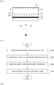
- FIG. 1 is a structural diagram of a micropattern layer based image film according to an embodiment of the present invention.
- the micropattern layer based image film includes a sacrificial layer 100, a separable release layer 110 formed on the sacrificial layer 100, a first micropattern layer 120 formed on the sacrificial layer, a second micropattern layer 130 formed on the first micropattern layer, a focal length layer 140 formed on the second micropattern layer, and a micro-image pattern 150 formed on the focal length layer 140.
- a direction in which the sacrificial layer 100 is viewed is a direction of line of sight.
- the release layer 110 serves to remove the sacrificial layer 100 from an image film and may be optionally employed.
- the first micropattern layer 120 includes a plurality of concave parts 121, and concave curved surfaces of the plurality of concave parts 121 are formed adjacent to the sacrificial layer 100.
- the second micropattern layer 130 includes a plurality of convex parts 131, and convex curved surfaces of the plurality of convex parts 131 are formed adjacent to the focal length layer.
- a pattern of the plurality of concave parts 121 of the first micropattern layer 120 and the plurality of convex parts 131 of the second micropattern layer 130 perform a microlens function.
- the first micropattern layer 120 and the second micropattern layer 130 are not shown to intersect with each other at a predetermined angle, but the first micropattern layer 120 and the second micropattern layer 130 may be formed to intersect with each other in a length direction of the pattern at an angle in a range of 88 degrees and 92 degrees.
- the first micropattern layer 120 and the second micropattern layer 130 may be disposed perpendicular to each other in the length direction.
- the plurality of concave parts 121 of the first micropattern layer 120 and the plurality of convex parts 131 of the second micropattern layer 130 are disposed adjacent to each other to form an egg shape.
- the plurality of concave parts 121 and the plurality of convex parts 131 may be in contact with each other or may be disposed within a distance of 10 ⁇ m from each other.
- the first micropattern layer 120, the second micropattern layer 130, and the focal length layer 140 may be made of an ultraviolet curable resin.
- the sacrificial layer may be made of poly-carbonate (PC) or polyethylene terephthalate (PET).
- the focal length layer may be formed to have a thickness in a range of 5 ⁇ m to 120 ⁇ m.
- the first micropattern layer 120, the second micropattern layer 130, and the focal length layer 140 may each have a predetermined refractive index such that the micro-image pattern 150 formed on the focal length layer 140 may be visually recognizable.
- n1 may be in a range of 1.2 to 1.5
- n2 may be in a range of 1.51 to 1.75
- n3 may be in a range of 1.2 to 1.5.
- a pitch between the plurality of concave parts 120 of the first micropattern layer 120 may have a size in a range of 5 ⁇ m to 60 ⁇ m
- a peak of each of the plurality of concave parts 120 may be manufactured to have a height in a range of 3 ⁇ m to 30 ⁇ m
- a pitch of the plurality of convex parts 131 of the second micropattern layer 130 may have a size in a range of 5 ⁇ m to 60 ⁇ m
- a peak of each of the plurality of convex parts 131 may be manufactured to have a height in a range of 3 ⁇ m to 30 ⁇ m.
- the pitch refers to a distance between two adjacent peaks of the concave parts 120 or the convex parts 131.
- an absolute value of a difference between P1 and P2 may be less than or equal to 1 ⁇ m.
- an absolute value of a difference between P1 and P3 may be less than or equal to 1 ⁇ m.
- the micropattern layer based image film forms an optical system of a multilayer structure through the arrangement, the refractive indexes, the thicknesses, the sizes of the pitches, and the heights of the peaks of the patterns of the micropattern layers. Consequently, an image of the micro-image pattern 150 may be accurately formed while reducing a thickness of the micropattern layer based image film.
- FIG. 2 is a flowchart illustrating a method of manufacturing a micropattern layer based image film according to an embodiment of the present invention.
- the first micropattern layer 120 is formed on the sacrificial layer 100 first (S100).
- the method of manufacturing a micropattern layer based image film according to the embodiment of the present invention is a method of sequentially forming multiple layers on a sacrificial layer 100 to form the image film and employs a method in which layers are sequentially formed upward from the sacrificial layer 100.
- the formation of the first micropattern layer 120 an ultraviolet curable resin is applied onto the sacrificial layer 100, a pattern surface of a first mold on which a micropattern is formed is positioned on the applied ultraviolet curable resin and pressed, and then ultraviolet light is emitted to transfer the micropattern on an upper surface of the ultraviolet curable resin.
- a pattern of the first micropattern layer 120 includes the plurality of concave parts 121.
- the second micropattern layer 130 is formed on the first micropattern layer 120 (S200).
- the second micropattern layer 130 is formed such that an ultraviolet curable resin is applied onto the first micropattern layer 120, a pattern surface of a second mold on which a micropattern is formed is positioned on the applied ultraviolet curable resin and pressed, and then ultraviolet light is emitted to transfer the micropattern on an upper surface of the ultraviolet curable resin.
- a pattern of the second micropattern layer 130 includes the plurality of convex parts 131.
- first micropattern layer 120 and the second micropattern layer 130 may be formed to intersect with each other in a length direction of the pattern at an angle in a range of 88 degrees and 92 degrees.
- the first micropattern layer 120 and the second micropattern layer 130 may be disposed perpendicular to each other.
- the focal length layer 140 is formed on the second micropattern layer 130 (S300), and the micro-image pattern 150 is formed on the focal length layer 140 (S400).
- operations S300 and S400 may be simultaneously performed, and the micro-image pattern 150 may be simultaneously formed while the focal length layer 140 is formed such that manufacturing efficiency may be maximized.
- the release layer 120 may be formed on the sacrificial layer 100.
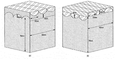
- FIG. 3 is a diagram showing a structure of the micropattern layer based image film according to the embodiment of the present invention and a structure of a Comparative Example.
- FIG. 3A is a structural diagram of the conventional image film for comparing with the micropattern layer based image film according to the embodiment of the present invention
- FIG. 3B is a structural diagram of the micropattern layer based image film according to the embodiment of the present invention.
- the conventional image film is configured in a structure in which a convex curve of a convex pattern of the first micropattern layer 120 and a concave curve of a concave pattern of the second micropattern layer 130 are formed in a direction approaching each other
- the micropattern layer based image film according to the embodiment of the present invention is configured in a structure in which a concave curve of the concave parts 121 of the first micropattern layer 120 and a convex curve of the convex parts 131 of the first micropattern layer 130 are formed in a direction away from each other.
- FIG. 4 is a diagram showing first simulation results of the micropattern layer based image film according to the embodiment of the present invention and Comparative Example.
- FIG. 4 a focal point of light with respect to each distance was confirmed based on vertexes (a valley or a peak of a pattern of the second micropattern layer) in the structures of FIG. 3A and 3B .
- the beam distribution of the micropattern layer based image film according to the embodiment of the present invention was more excellent and had a short focal length as compared with the conventional image film.
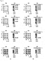
- FIG. 5 is a diagram showing second simulation results of the micropattern layer based image film according to the embodiment of the present invention and Comparative Example.
- FIG. 5 shows a degree of a beam distribution at a distance of 60 mm.
- FIG. 5A shows a simulation result with respect to the conventional image film
- FIG. 5B is a simulation result with respect to the micropattern layer based image film according to the embodiment of the present invention.
- the micropattern layer based image film according to the embodiment of the present invention formed an image having a smaller size and had a short focal length as compared with the conventional image film.
- FIG. 6 is a diagram illustrating third simulation results of the micropattern layer based image film according to the embodiment of the present invention and Comparative Example.
- FIG. 6 shows a degree of a beam distribution at a distance of 70 mm.
- FIG. 6A shows a simulation result with respect to the conventional image film
- FIG. 6B is a simulation result with respect to the micropattern layer based image film according to the embodiment of the present invention.
- the micropattern layer based image film according to the embodiment of the present invention formed an image having a smaller size and had a short focal length as compared with the conventional image film.
- a focal length can be shorter to reduce a thickness of the focal length layer. Consequently, an overall thickness of the micropattern layer based image film can be drastically reduced.
Landscapes
- Engineering & Computer Science (AREA)
- Physics & Mathematics (AREA)
- Manufacturing & Machinery (AREA)
- Mechanical Engineering (AREA)
- General Physics & Mathematics (AREA)
- Optics & Photonics (AREA)
- Health & Medical Sciences (AREA)
- Ophthalmology & Optometry (AREA)
- Plasma & Fusion (AREA)
- Thermal Sciences (AREA)
- Laminated Bodies (AREA)
Applications Claiming Priority (2)
| Application Number | Priority Date | Filing Date | Title |
|---|---|---|---|
| KR1020170108107A KR101861655B1 (ko) | 2017-08-25 | 2017-08-25 | 마이크로 패턴층 기반의 이미지 필름 |
| PCT/KR2017/013720 WO2019039660A1 (ko) | 2017-08-25 | 2017-11-28 | 마이크로 패턴층 기반의 이미지 필름 |
Publications (2)
| Publication Number | Publication Date |
|---|---|
| EP3674075A1 true EP3674075A1 (de) | 2020-07-01 |
| EP3674075A4 EP3674075A4 (de) | 2020-09-02 |
Family
ID=62451226
Family Applications (1)
| Application Number | Title | Priority Date | Filing Date |
|---|---|---|---|
| EP17922678.2A Withdrawn EP3674075A4 (de) | 2017-08-25 | 2017-11-28 | Bildfilm auf der grundlage einer mikromusterschicht |
Country Status (5)
| Country | Link |
|---|---|
| US (1) | US11453185B2 (de) |
| EP (1) | EP3674075A4 (de) |
| KR (1) | KR101861655B1 (de) |
| CN (1) | CN109982835B (de) |
| WO (1) | WO2019039660A1 (de) |
Families Citing this family (4)
| Publication number | Priority date | Publication date | Assignee | Title |
|---|---|---|---|---|
| HUE054917T2 (hu) | 2016-03-01 | 2021-10-28 | The Fynder Group Inc | Gombafonalas bioszõnyegek, ezek elõállítási módszerei és felhasználási módjai |
| KR102101628B1 (ko) * | 2018-08-24 | 2020-04-20 | 주식회사 상보 | 이미지 필름 및 전사재 |
| KR102064779B1 (ko) | 2019-04-23 | 2020-01-10 | 유정찬 | 광 확산을 이용한 한글 시계 |
| CN112505938B (zh) * | 2019-08-26 | 2022-07-05 | 昇印光电(昆山)股份有限公司 | 立体成像膜 |
Family Cites Families (7)
| Publication number | Priority date | Publication date | Assignee | Title |
|---|---|---|---|---|
| US6061179A (en) * | 1996-01-23 | 2000-05-09 | Canon Kabushiki Kaisha | Stereoscopic image display apparatus with two-/three-dimensional image display switching function |
| KR101131642B1 (ko) * | 2010-03-24 | 2012-03-28 | 김장규 | 입체이미지 필름 및 그 제조방법 |
| KR101203199B1 (ko) | 2012-02-03 | 2012-11-21 | (주)쓰리에스엠케이 | 입체 보안요소가 구비된 사출품과 그 제작 방법 |
| KR101341072B1 (ko) | 2013-09-04 | 2013-12-19 | 안재광 | 복수의 나노 구조물 및 입체 렌즈를 이용한 진품 확인용 라벨 |
| CN105425406A (zh) * | 2015-12-17 | 2016-03-23 | 张家港康得新光电材料有限公司 | 3d显示膜及立体显示装置 |
| KR101644830B1 (ko) * | 2016-01-29 | 2016-08-11 | 주식회사 우리옵토 | 미크론 단위 두께를 가지는 마이크로 렌즈 기반의 보안 이미지 필름 제조 방법 |
| KR101666819B1 (ko) * | 2016-01-29 | 2016-10-28 | 주식회사 비주얼넷 | 미크론 단위 두께를 가지는 렌티큘러 렌즈 기반의 보안 이미지 필름 제조 방법 |
-
2017
- 2017-08-25 KR KR1020170108107A patent/KR101861655B1/ko active Active
- 2017-11-28 CN CN201780052536.XA patent/CN109982835B/zh active Active
- 2017-11-28 WO PCT/KR2017/013720 patent/WO2019039660A1/ko not_active Ceased
- 2017-11-28 EP EP17922678.2A patent/EP3674075A4/de not_active Withdrawn
-
2019
- 2019-06-20 US US16/447,590 patent/US11453185B2/en active Active
Also Published As
| Publication number | Publication date |
|---|---|
| KR101861655B1 (ko) | 2018-05-28 |
| WO2019039660A1 (ko) | 2019-02-28 |
| US20190299506A1 (en) | 2019-10-03 |
| CN109982835A (zh) | 2019-07-05 |
| US11453185B2 (en) | 2022-09-27 |
| CN109982835B (zh) | 2021-04-27 |
| EP3674075A4 (de) | 2020-09-02 |
Similar Documents
| Publication | Publication Date | Title |
|---|---|---|
| US11453185B2 (en) | Micropattern layer based image film | |
| US7394596B1 (en) | Plane lens sheet using light transmission rate difference | |
| US10126537B2 (en) | Marker | |
| WO2020096771A1 (en) | Depth-modulated slanted gratings using gray-tone lithography and slant etch | |
| KR101042501B1 (ko) | 광 투과 조정 필터가 형성된 렌즈 어레이 시트 | |
| US8503083B2 (en) | Lens sheet for microlens and lenticular lens | |
| US10151880B2 (en) | Optical light guide element and a method for manufacturing | |
| US20150261000A1 (en) | 3d image displaying object, production method, and production system thereof | |
| US20160299263A1 (en) | Microlens array, manufacturing method thereof, image acquisition device, and display device | |
| JP6357361B2 (ja) | 再帰性反射体及びこれを利用した立体像表示装置 | |
| CN104181698A (zh) | 对位标靶及具有其的3d柱镜膜、光学膜和显示装置 | |
| CN115981025A (zh) | 微光学成像系统及其制作方法 | |
| KR101644830B1 (ko) | 미크론 단위 두께를 가지는 마이크로 렌즈 기반의 보안 이미지 필름 제조 방법 | |
| CN205384410U (zh) | 3d显示膜及立体显示装置 | |
| WO2015127705A1 (zh) | 显示装置 | |
| US20180149879A1 (en) | Display body including partially-provided optical element array | |
| JP5723928B2 (ja) | モールド型の製造方法 | |
| KR20180010791A (ko) | 지향성 백라이트 유닛, 이의 제작방법, 이를 포함하는 입체 영상 표시 장치 | |
| KR101666819B1 (ko) | 미크론 단위 두께를 가지는 렌티큘러 렌즈 기반의 보안 이미지 필름 제조 방법 | |
| CN104122672A (zh) | 一种基于微球形透镜阵列的3d显示器 | |
| JP6105465B2 (ja) | 立体像形成装置の製造方法 | |
| JP6116534B2 (ja) | 再帰性反射体の製造方法 | |
| JP2013178363A (ja) | 画像記録媒体、及びその製造方法 | |
| RU2629150C1 (ru) | Устройство для формирования динамического изображения и способ его получения | |
| TWI579594B (zh) | 3d顯示層、3d顯示結構及其製作方法 |
Legal Events
| Date | Code | Title | Description |
|---|---|---|---|
| STAA | Information on the status of an ep patent application or granted ep patent |
Free format text: STATUS: THE INTERNATIONAL PUBLICATION HAS BEEN MADE |
|
| PUAI | Public reference made under article 153(3) epc to a published international application that has entered the european phase |
Free format text: ORIGINAL CODE: 0009012 |
|
| STAA | Information on the status of an ep patent application or granted ep patent |
Free format text: STATUS: REQUEST FOR EXAMINATION WAS MADE |
|
| 17P | Request for examination filed |
Effective date: 20200317 |
|
| AK | Designated contracting states |
Kind code of ref document: A1 Designated state(s): AL AT BE BG CH CY CZ DE DK EE ES FI FR GB GR HR HU IE IS IT LI LT LU LV MC MK MT NL NO PL PT RO RS SE SI SK SM TR |
|
| AX | Request for extension of the european patent |
Extension state: BA ME |
|
| A4 | Supplementary search report drawn up and despatched |
Effective date: 20200731 |
|
| RIC1 | Information provided on ipc code assigned before grant |
Ipc: G02B 3/00 20060101ALI20200727BHEP Ipc: B32B 27/36 20060101ALI20200727BHEP Ipc: B32B 37/02 20060101ALI20200727BHEP Ipc: B32B 27/08 20060101ALI20200727BHEP Ipc: B32B 38/06 20060101ALI20200727BHEP Ipc: B32B 7/06 20190101ALI20200727BHEP Ipc: B29D 11/00 20060101ALI20200727BHEP Ipc: G02B 30/27 20200101ALI20200727BHEP Ipc: B32B 3/30 20060101AFI20200727BHEP Ipc: B32B 38/00 20060101ALI20200727BHEP |
|
| DAV | Request for validation of the european patent (deleted) | ||
| DAX | Request for extension of the european patent (deleted) | ||
| STAA | Information on the status of an ep patent application or granted ep patent |
Free format text: STATUS: EXAMINATION IS IN PROGRESS |
|
| 17Q | First examination report despatched |
Effective date: 20220414 |
|
| STAA | Information on the status of an ep patent application or granted ep patent |
Free format text: STATUS: THE APPLICATION IS DEEMED TO BE WITHDRAWN |
|
| 18D | Application deemed to be withdrawn |
Effective date: 20220825 |