EP3674119B1 - Capote soft-top pour véhicule cabriolet doté d'un étrier de retenue - Google Patents
Capote soft-top pour véhicule cabriolet doté d'un étrier de retenue Download PDFInfo
- Publication number
- EP3674119B1 EP3674119B1 EP19219111.2A EP19219111A EP3674119B1 EP 3674119 B1 EP3674119 B1 EP 3674119B1 EP 19219111 A EP19219111 A EP 19219111A EP 3674119 B1 EP3674119 B1 EP 3674119B1
- Authority
- EP
- European Patent Office
- Prior art keywords
- tension rod
- soft top
- hood
- bar linkage
- support element
- Prior art date
- Legal status (The legal status is an assumption and is not a legal conclusion. Google has not performed a legal analysis and makes no representation as to the accuracy of the status listed.)
- Active
Links
Images


Classifications
-
- B—PERFORMING OPERATIONS; TRANSPORTING
- B60—VEHICLES IN GENERAL
- B60J—WINDOWS, WINDSCREENS, NON-FIXED ROOFS, DOORS, OR SIMILAR DEVICES FOR VEHICLES; REMOVABLE EXTERNAL PROTECTIVE COVERINGS SPECIALLY ADAPTED FOR VEHICLES
- B60J7/00—Non-fixed roofs; Roofs with movable panels, e.g. rotary sunroofs
- B60J7/08—Non-fixed roofs; Roofs with movable panels, e.g. rotary sunroofs of non-sliding type, i.e. movable or removable roofs or panels, e.g. let-down tops or roofs capable of being easily detached or of assuming a collapsed or inoperative position
- B60J7/12—Non-fixed roofs; Roofs with movable panels, e.g. rotary sunroofs of non-sliding type, i.e. movable or removable roofs or panels, e.g. let-down tops or roofs capable of being easily detached or of assuming a collapsed or inoperative position foldable; Tensioning mechanisms therefor, e.g. struts
- B60J7/1226—Soft tops for convertible vehicles
- B60J7/1234—Soft tops for convertible vehicles characterised by arches, e.g. shape or material
- B60J7/1247—Tensioning bow at rear of soft top
-
- B—PERFORMING OPERATIONS; TRANSPORTING
- B60—VEHICLES IN GENERAL
- B60J—WINDOWS, WINDSCREENS, NON-FIXED ROOFS, DOORS, OR SIMILAR DEVICES FOR VEHICLES; REMOVABLE EXTERNAL PROTECTIVE COVERINGS SPECIALLY ADAPTED FOR VEHICLES
- B60J7/00—Non-fixed roofs; Roofs with movable panels, e.g. rotary sunroofs
- B60J7/185—Locking arrangements
- B60J7/1856—Locking arrangements for interlocking the roof linkage system when deployed
Definitions
- the invention relates to a soft top convertible top for a convertible vehicle, which can be displaced by means of a convertible top linkage between an open position that at least partially releases a passenger compartment and a closed position that covers the passenger compartment, according to the type defined in more detail in the preamble of claim 1.
- Convertible vehicles with displaceable tops are known from practice, in which the top can be displaced between a closed position and an open position by means of a main four-bar mechanism comprising a main link and a main column.
- the main pillar and the main link in addition to the articulation fixed to the body, are articulated to a main bearing on a roof frame which is arranged in the closed top position on the front of the main pillar and which is part of the main four-bar mechanism.
- a fabric retainer is provided for tensioning a convertible top cover, which when the convertible top is closed, independently of the main four-bar mechanism, from a position that clamps the convertible top cover, in which the fabric retainer lies in particular on a convertible top compartment lid and / or trunk lid, and an open position pivoted upwards with a rear area is relocatable.
- Such a top is for example in the EP 2 098 398 A2 described.
- a desired stiffness of the convertible top in the closed convertible top position may be difficult to achieve, especially with a large extension in the longitudinal direction of the vehicle, with convertible tops designed in this way.
- a hard-top roof which can be displaced between an open and a closed position by two arms that form a four-bar linkage and are fixed to the body.
- an eccentric is provided which is connected to one arm and which interacts with the other arm in the closed roof position. In the closed roof position, the eccentric pushes the two arms apart, whereby a tension can be induced between the two arms.
- a similar design of a hard-top roof is from the DE 603 04 742 T2 known, with an adjustable stop means being provided instead of the eccentric.
- a soft-top convertible top is provided for a convertible vehicle, which can be displaced by means of a convertible top linkage between an open position that at least partially releases a passenger compartment and a closed position covering the passenger compartment Roof frame executed Has four-bar mechanism, the main link and the main pillar each being connected to the roof frame at a point of articulation, with a fabric retaining bracket designed to tension a convertible top cover and a displacement mechanism for displacing the fabric retaining bracket from a closed position that spans the convertible top cover into an open position that is pivoted upwards with a rear area Position is provided independently of the four-bar mechanism, and wherein the displacement mechanism has a tie rod articulated to the four-bar mechanism.
- the tensioning rod in the closed top position with the fabric retaining bar closed to stiffen the top rests against the four-bar mechanism in particular in a support area, the tensioning bar forming a support for the four-bar mechanism against a force acting downward in the vertical direction of the vehicle.
- the inventive design of the soft-top convertible top makes it possible to achieve rigidity of the convertible top in the closed position in a structurally simple manner, even without the application of a large pre-tensioning force, since the tie rod enables the four-bar mechanism in an additional support area with the roof frame, in particular a so-called insert of the roof frame.
- the support area is in particular arranged at a distance from a hinge point in which the tension rod is connected to the four-bar mechanism.
- a shift of the main pillar or the main link in the closed top position relative to the roof frame in the vertical direction of the vehicle under the action of an external, at least partially downward force, is made more difficult by the interaction of the tension rod with the four-bar mechanism.
- the closed top position there is a relative movement of the main link or the main pillar blocked with respect to the roof frame, so that a rigidity of the top is increased.
- the tensioning rod can be part of a two-part, three-part or multi-part tensioning device of the displacement mechanism for the fabric holding bracket, with another tensioning rod being articulated to the fabric holding bracket and interacting directly or via the interposition of one or more additional tensioning rods with the tensioning rod linked to the four-bar mechanism.
- the convertible top starting from the fabric retaining bar in the open position, is moved together with the rest of the convertible top into the rear storage space, whereby the time for moving the convertible top between the open position and the closed position is advantageously short is.
- the tensioning rod can rest against the four-bar mechanism from below in the closed convertible top and fabric holding bar position at least in some areas with respect to a convertible top upward direction.
- the tensioning rod When the tensioning rod is pivoted upwards during a closing movement of the fabric holding bar with an end region facing away from the articulation on the four-bar mechanism, the tensioning rod interacts with the four-bar mechanism in the closed top and fabric holding bar position can be achieved in a structurally simple manner with an associated increase in the rigidity of the convertible top.
- a hinge point in which the tension rod is connected to the four-bar mechanism can be located in the longitudinal direction of the convertible top in front of the hinge point be arranged in which the main pillar is connected to the roof frame.
- the hinge point at which the tension rod is connected to the four-bar mechanism is preferably arranged in the longitudinal direction of the convertible top behind the hinge point at which the main link is connected to the roof frame.
- the tension rod can be articulated at a pivot point on the main link or on the main pillar.
- the tensioning rod can have a support element which, in the closed top position with the fabric retaining bar closed, rests against a support element of the four-bar mechanism to stiffen the top through an interaction of the four-bar mechanism with the roof frame, in particular the insert of the roof frame. This makes it difficult in a simple manner to shift the main pillar or the main link in the closed top position relative to the roof frame in the vertical direction of the vehicle.
- the support element of the tension rod preferably forms a stop for the support element of the four-bar mechanism, so that the main link or the main pillar of the four-bar mechanism is supported on the roof frame by the interaction of the support elements in the closed top position.
- the tension rod can be articulated in such a way that the support element of the tension rod during an opening movement of the fabric retainer comes out of engagement with the support element of the four-bar mechanism and, in particular, comes into engagement with the support element when the fabric retainer is transferred from the open position to the closed position.
- the support element of the tensioning rod is preferably designed integrally with the tensioning rod, but in an alternative embodiment according to the invention it can also be designed as a separate element.
- the support element of the tension rod is designed as an extension arm of the tension rod, which in the closed top and fabric holding bar position engages under the support element of the four-bar mechanism at least in some areas and in particular rests against the support element of the four-bar mechanism from below.
- the support element of the four-bar mechanism is preferably arranged on the main link or the main pillar or is designed integrally with one of these components.
- the support element of the four-bar mechanism is designed as a separate component that is connected to the main link or the main pillar.
- an adjustment device can be provided by means of which the component is adjustably connected to the main link or the main pillar.
- the support element of the tension rod can be designed as a pin which engages in a recess of the support element of the four-bar mechanism in the closed top and fabric holding bar position.
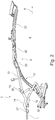
- Fig. 1 shows a convertible vehicle 1 with a convertible top 2 designed as a soft top.
- the top 2 covered by a top cover 3 is shown in a closed position in which the top 2 covers a passenger compartment 4.
- the convertible top 2 extends from a windshield frame 6, which is arranged in a front area in the direction of travel 5 and on which the convertible top 2 can be locked in particular by means of a locking device, to a rear-side fabric retaining bracket 7 or tensioning bracket, which in the closed position on a convertible top compartment lid 8 and / or rests on a trunk lid while tensioning the top cover 3.
- the convertible top 2 is from the in Fig. 1
- the closed position shown can be displaced by means of a convertible top linkage 9 into an open position that at least partially releases the passenger compartment 4, in which the convertible top 2 is stored in a rear vehicle area in a storage space 10 covered by the convertible top compartment cover 8.
- this can in particular also be used as a trunk.
- the convertible top compartment lid 8 can be pivoted open at least to release a passage opening for the convertible top 2 in an area with a front area in the direction of travel 5.
- This opening movement can be a pure pivoting movement or a combined translational and rotary movement.
- the top linkage 9 has a four-bar mechanism 17 on both sides with a main link 18 and a main pillar 19, each of which is arranged at one end on a main bearing 20 of the top 2 fixed to the body and with an area facing away from the main bearing 20, each with a main pillar 19 in the closed top position upstream roof frame 21 or a so-called insert 22 of the roof frame 21 are connected.
- a further roof frame 23 is provided, which is arranged in the closed convertible top position in front of the roof frame 21 and has a roof tip 24 in a front region, by means of which the convertible top 2 can be fixed to the windshield frame 6.
- the convertible top 2 is thus essentially constructed in three parts and can be displaced into the storage space 10 in a Z-shaped movement.
- the top 2 can in principle also be designed in two parts with only one roof frame 21 in front of the main pillar 19 or in four or more parts with other roof frames in front of the roof frame 23, with a displacement movement for moving the top 2 between the closed position and the open position basically being freely selectable is.
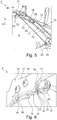
- the displacement mechanism 12 for displacing the fabric retainer 7 between the closed position resting on the convertible top compartment lid 8 and a position pivoted open with the rear area, in which the convertible top compartment lid 8 can be displaced between the closed position and the open position.
- the fabric retainer 7 is connected in an articulated manner to the convertible top linkage 9, in particular the main link 18 or the main pillar 19 of the four-bar mechanism 17.
- the displacement mechanism 12 in the present case has a tensioning device 15 embodied with two tensioning rods 13, 14 or a dead center linkage, a first tensioning rod 13 being connected to the main link 18 at a first articulation point 25. In an area facing away from the first hinge point 25, the first tensioning rod 13 is connected at a second hinge point 26 to the second tensioning rod 14, which in turn is connected in an area facing away from the hinge point 26 in a third hinge point 27 with the fabric holder 7.
- the first hinge point 25 is in the closed top position in the direction of travel 5 in front of a hinge point 30, at which the main pillar 19 is connected to the insert 22, and behind a hinge point 31, at which the main link 18 is connected to the insert 22.
- the fabric retainer 7 can be displaced from the closed position into the open position by means of the displacement mechanism 12 independently of the four-bar mechanism 17, the first tensioning rod 13, as in FIG Fig. 3 can be seen, here pivoted downward with an end facing away from the first hinge point 25.
- the convertible top compartment cover 8 can be moved into its position releasing the storage space 10, and the convertible top 2 as a whole can be moved into the storage space 10.
- the fabric retainer 7 is moved from the open position together with the rest of the convertible top 2 into the storage space 10. In an alternative embodiment, it can be provided that the fabric retainer 7 is first moved back into its closed position or a position close to it, before the entire convertible top 2 is moved into the storage space 10.
- Fig. 7 is a state shortly before reaching the The closed position of the fabric retainer 7 is shown when the convertible top 2 is otherwise already in the closed position.
- the first tension rod 13 has a support element 33 which is embodied here integrally with the first tension rod 13, which is designed to interact with a support element 34 of the main link 18 and forms a stop for the support element 34 of the main link 18.
- the support element 34 of the main link 18 is in the present case a separate component which is arranged on the main link 18 so as to be adjustable via an adjusting device 38 embodied here with two screw connections 39, 40.
- the support element 33 of the first tension rod 13 and the support element 34 of the main link 18 are matched to one another in such a way that the support element 33 of the first tension rod 13 at least partially from below in a support area 32 in contact with the support element 34 of the main link 18 during a closing movement of the fabric holder 7 comes and in particular rests flat on this.
- the support element 33 of the first tensioning rod 13 has a nose-shaped arm 35 which, by means of an outer contour 36, interacts with an outer contour 37 of the support element 34 of the main link 18 that is coordinated therewith.
- the support element 33 of the first tensioning rod 13 rests against the outer contour 36 of the support element 34 of the main link 18 at least in some areas from below in the vertical direction of the vehicle and possibly also in the longitudinal direction of the vehicle.
- wedging or blocking on tension and secure and stable support of the main link 18 with respect to the insert 22 of the roof frame 21 by means of the first tension rod 13 is achieved.
- the tensioning device 15 blocks a downward displacement movement of the main link 18 and stiffens the convertible top 2, in particular the convertible top linkage 9, in a structurally simple manner.
- a separate drive is advantageously not required for this, since the movement of the tension rod 13 is used for this purpose.
- a bending or bending of the top 2 by a force that occurs during operation and acts downwards - according to arrow 42 - is thus advantageously reduced even in the case of a convertible top 2 that has a long extension and / or is of lightweight construction.
- a kinematic support 43 is shown, which results from a connection of the hinge point 30 of the main link 18 with the insert 22 and a hinge point 44 of the main link 18 in the main bearing 20.
- the fabric retainer 7 is pivoted with its rear end upwards, with the support element 33 of the first tensioning rod 13 being moved downwards away from the support element 34 of the main link 18 and thereby a displacement movement of the convertible top 2 from the closed position in the direction of the open position is released.
Landscapes
- Engineering & Computer Science (AREA)
- Mechanical Engineering (AREA)
- Body Structure For Vehicles (AREA)
Claims (15)
- Capote souple (2) pour un véhicule cabriolet (1), qui peut être déplacée au moyen d'une tringlerie de capote (9) entre une position ouverte découvrant au moins partiellement un habitacle (4) et une position fermée recouvrant ledit habitacle (4),où la tringlerie de capote (9) comprend un mécanisme à quatre articulations (17) réalisé avec un bras principal (18), un montant principal (19) et un cadre de toit (21),où le bras principal (18) et le montant principal (19) sont chacun reliés au cadre de toit (21) en un point d'articulation (31 et 30 respectivement), et où un étrier de retenue (7) adapté pour serrer un recouvrement de capote (3) et un mécanisme de déplacement (12) pour déplacer l'étrier de retenue (7) entre une position fermée serrant le recouvrement de capote (3) et une position ouverte pivotée vers le haut avec une partie latérale arrière indépendamment du mécanisme à quatre articulations (17) sont prévus,le mécanisme de déplacement (12) comprenant une tige de serrage (13) reliée de manière articulée au mécanisme à quatre articulations (17), caractérisée en ce que que la tige de serrage (13), dans la position fermée de la capote avec l'étrier de retenue (7) fermé, s'appuie contre le mécanisme à quatre articulations (17) afin de raidir la capote (2), la tige de serrage (13) formant un support pour le mécanisme à quatre articulations (17) contre une force agissant vers le bas dans la direction verticale du véhicule.
- Capote souple selon la revendication 1, caractérisée en ce que la tige de serrage (13), dans la position fermée de la capote et de l'étrier de retenue, s'appuie par en dessous, par rapport à une direction verticale de la capote, contre le bras principal (18) ou le montant principal (19) du mécanisme à quatre articulations (17), au moins dans certaines régions.
- Capote souple selon l'une quelconque des revendications 1 ou 2, caractérisée en ce que la tige de serrage (13) est pivotée vers le haut avec une région d'extrémité opposée à l'articulation sur le mécanisme à quatre articulations (17) lors d'un mouvement de fermeture de l'étrier de retenue (7).
- Capote souple selon l'une quelconque des revendications 1 à 3, caractérisée en ce que, dans la position fermée de la capote, un point d'articulation (25) au niveau duquel la tige de serrage (13) est reliée au mécanisme à quatre articulations (17) est disposé, dans la direction longitudinale de la capote, devant le point d'articulation (30) au niveau duquel le montant principal (19) est relié au cadre de toit (21).
- Capote souple selon l'une quelconque des revendications 1 à 4, caractérisée en ce que la tige de serrage (13) est articulée sur le bras principal (18) en un point d'articulation (25).
- Capote souple selon l'une quelconque des revendications 1 à 5, caractérisée en ce que la tige de serrage (13) est articulée sur le montant principal (19) en un point d'articulation.
- Capote souple selon l'une quelconque des revendications 1 à 6, caractérisée en ce que la tige de serrage (13) comporte un élément de support (33) qui, dans la position fermée de la capote lorsque l'étrier de retenue (7) est fermé, repose sur un élément de support (34) du mécanisme à quatre articulations (17).
- Capote souple selon la revendication 7, caractérisée en ce que l'élément de support (33) de la tige de serrage (13) constitue une butée pour l'élément de support (34) du mécanisme à quatre articulations (17).
- Capote souple selon l'une quelconque des revendications 7 ou 8, caractérisée en ce que la tige de serrage (13) est articulée de telle sorte que l'élément de support (33) de la tige de serrage (13) se désengage de l'élément de support (34) du mécanisme à quatre articulations (17) lors d'un mouvement d'ouverture de l'étrier de retenue (7).
- Capote souple selon l'une quelconque des revendications 7 à 9, caractérisée en ce que l'élément de support (33) de la tige de serrage (13) est solidaire de la tige de serrage (13).
- Capote souple selon l'une quelconque des revendications 7 à 10, caractérisée en ce que l'élément de support (33) de la tige de serrage (13) est réalisé sous la forme d'un bras (35) de la tige de serrage (13) qui, en position fermée de la capote et de l'étrier de retenue, vient en prise au moins partiellement sous l'élément de support (34) du mécanisme à quatre articulations (17).
- Capote souple selon l'une quelconque des revendications 7 à 11, caractérisée en ce que l'élément de support (34) du mécanisme à quatre articulations (17) est disposé sur le bras principal (18) ou le montant principal (19).
- Capote souple selon l'une quelconque des revendications 7 à 12, caractérisée en ce que l'élément de support (34) du mécanisme à quatre articulations (17) est réalisé sous forme d'un composant séparé relié au bras principal (18) ou au montant principal (19).
- Capote souple selon la revendication 13, caractérisée en ce qu'il est prévu un dispositif de réglage (38) au moyen duquel le composant (34) est relié de manière réglable au bras principal (18) ou au montant principal (19).
- Capote souple selon l'une quelconque des revendications 7 à 14, caractérisée en ce que l'élément de support (33) de la tige de serrage (13) est réalisé sous forme d'un tenon qui vient en prise dans un évidement de l'élément de support (34) du mécanisme à quatre articulations (17) lorsque la capote et l'étrier de retenue sont en position fermée.
Applications Claiming Priority (1)
| Application Number | Priority Date | Filing Date | Title |
|---|---|---|---|
| DE102018133720.5A DE102018133720A1 (de) | 2018-12-31 | 2018-12-31 | Soft-Top-Verdeck für ein Cabriolet-Fahrzeug mit einem Stoffhaltebügel |
Publications (2)
| Publication Number | Publication Date |
|---|---|
| EP3674119A1 EP3674119A1 (fr) | 2020-07-01 |
| EP3674119B1 true EP3674119B1 (fr) | 2021-11-10 |
Family
ID=69005466
Family Applications (1)
| Application Number | Title | Priority Date | Filing Date |
|---|---|---|---|
| EP19219111.2A Active EP3674119B1 (fr) | 2018-12-31 | 2019-12-20 | Capote soft-top pour véhicule cabriolet doté d'un étrier de retenue |
Country Status (2)
| Country | Link |
|---|---|
| EP (1) | EP3674119B1 (fr) |
| DE (1) | DE102018133720A1 (fr) |
Family Cites Families (7)
| Publication number | Priority date | Publication date | Assignee | Title |
|---|---|---|---|---|
| FR2802478B1 (fr) | 1999-12-20 | 2002-03-01 | France Design | Toit retractable dans le coffre arriere d'un vehicule |
| DE50104354D1 (de) * | 2000-06-15 | 2004-12-09 | Karmann Gmbh W | Cabriolet-Fahrzeug |
| FR2848921B1 (fr) | 2002-12-20 | 2005-02-04 | France Design | Dispositf de mise en tension du toit retractable d'un vehicule automobile |
| DE102007061681B3 (de) * | 2007-12-18 | 2009-04-02 | Webasto Ag | Faltverdeck mit einem Verdeckbezug |
| DE102008012887B4 (de) * | 2008-03-06 | 2021-10-14 | Valmet Automotive Oy | Verdeck eines Cabriolet-Fahrzeugs |
| DE102010007731A1 (de) * | 2010-02-12 | 2011-08-18 | Magna Car Top Systems GmbH, 74321 | Sturmstangeneinrichtung für ein Faltverdeck |
| DE202011101129U1 (de) * | 2011-05-26 | 2011-07-25 | Magna Car Top Systems Gmbh | Verstellbares Fahrzeugdach mit einem Faltverdeck |
-
2018
- 2018-12-31 DE DE102018133720.5A patent/DE102018133720A1/de not_active Withdrawn
-
2019
- 2019-12-20 EP EP19219111.2A patent/EP3674119B1/fr active Active
Also Published As
| Publication number | Publication date |
|---|---|
| EP3674119A1 (fr) | 2020-07-01 |
| DE102018133720A1 (de) | 2020-07-02 |
Similar Documents
| Publication | Publication Date | Title |
|---|---|---|
| DE10041487A1 (de) | Versenkbare Heckscheibe, insbesondere Festglasscheibe für ein Faltverdeck in einem Kraftfahrzeug | |
| DE19934892C1 (de) | Verstellbares Faltdach für ein Kraftfahrzeug | |
| EP1403116B1 (fr) | Véhicule convertible avec toit pliant rétractable | |
| DE10247724B3 (de) | Cabriolet-Fahrzeug mit das Verdeck aufnehmendem Verdeckkasten | |
| EP1990223B1 (fr) | Capote d'un véhicule cabriolet | |
| EP3674119B1 (fr) | Capote soft-top pour véhicule cabriolet doté d'un étrier de retenue | |
| EP2280840B1 (fr) | Capote pour un véhicule, notamment un véhicule décapotable, doté d'un toit pliant | |
| DE10354291B3 (de) | Hutablage für ein Cabriolet-Fahrzeug | |
| DE102013114984A1 (de) | Verdeck eines Cabriolet-Fahrzeugs mit einer Antriebseinrichtung | |
| DE102012025397A1 (de) | Faltverdeck für ein Cabriolet-Fahrzeug | |
| EP1758752B1 (fr) | Voiture cabriolet | |
| EP2382104B1 (fr) | Pavillon de cabriolet avec au moins deux segments de toit et une garniture | |
| EP2755837B1 (fr) | Dispositif d'actionnement d'un hayon de véhicule relevable en deux parties | |
| EP1745962B1 (fr) | Toit ouvrant pour véhicule | |
| DE102007050210A1 (de) | Schwenkeinrichtung für einen Deckel | |
| EP2889170B1 (fr) | Toit pour un véhicule cabriolet doté d'un élément de toit arrière mobile | |
| DE102006052596A1 (de) | Verdeck für ein Kraftfahrzeug, insbesondere Cabriolet-Fahrzeug, mit einem faltbaren Dach | |
| EP3505377B1 (fr) | Capote soft-top d'un véhicule cabriolet dotée d'un dispositif de tige de serrage | |
| EP2383135B1 (fr) | Couvercle mobile | |
| DE102017002291B4 (de) | Verdeck eines Cabriolet-Fahrzeugs | |
| DE102016015605B4 (de) | Verdeck-Vorrichtung eines Cabriolet-Fahrzeugs | |
| DE102014119721B4 (de) | Cabriolet-Fahrzeug mit hinteren Seitenscheiben | |
| DE102014210956B4 (de) | Dachanordnung für ein Kraftfahrzeug | |
| EP2483095B1 (fr) | Toit souple pour un véhicule cabriolet | |
| DE102007023116A1 (de) | Verdeck eines Cabriolet-Fahrzeugs |
Legal Events
| Date | Code | Title | Description |
|---|---|---|---|
| PUAI | Public reference made under article 153(3) epc to a published international application that has entered the european phase |
Free format text: ORIGINAL CODE: 0009012 |
|
| STAA | Information on the status of an ep patent application or granted ep patent |
Free format text: STATUS: THE APPLICATION HAS BEEN PUBLISHED |
|
| AK | Designated contracting states |
Kind code of ref document: A1 Designated state(s): AL AT BE BG CH CY CZ DE DK EE ES FI FR GB GR HR HU IE IS IT LI LT LU LV MC MK MT NL NO PL PT RO RS SE SI SK SM TR |
|
| AX | Request for extension of the european patent |
Extension state: BA ME |
|
| STAA | Information on the status of an ep patent application or granted ep patent |
Free format text: STATUS: REQUEST FOR EXAMINATION WAS MADE |
|
| 17P | Request for examination filed |
Effective date: 20210111 |
|
| RBV | Designated contracting states (corrected) |
Designated state(s): AL AT BE BG CH CY CZ DE DK EE ES FI FR GB GR HR HU IE IS IT LI LT LU LV MC MK MT NL NO PL PT RO RS SE SI SK SM TR |
|
| GRAP | Despatch of communication of intention to grant a patent |
Free format text: ORIGINAL CODE: EPIDOSNIGR1 |
|
| STAA | Information on the status of an ep patent application or granted ep patent |
Free format text: STATUS: GRANT OF PATENT IS INTENDED |
|
| RIC1 | Information provided on ipc code assigned before grant |
Ipc: B60J 7/12 20060101AFI20210616BHEP Ipc: B60J 7/185 20060101ALI20210616BHEP |
|
| INTG | Intention to grant announced |
Effective date: 20210712 |
|
| GRAS | Grant fee paid |
Free format text: ORIGINAL CODE: EPIDOSNIGR3 |
|
| GRAA | (expected) grant |
Free format text: ORIGINAL CODE: 0009210 |
|
| STAA | Information on the status of an ep patent application or granted ep patent |
Free format text: STATUS: THE PATENT HAS BEEN GRANTED |
|
| AK | Designated contracting states |
Kind code of ref document: B1 Designated state(s): AL AT BE BG CH CY CZ DE DK EE ES FI FR GB GR HR HU IE IS IT LI LT LU LV MC MK MT NL NO PL PT RO RS SE SI SK SM TR |
|
| REG | Reference to a national code |
Ref country code: GB Ref legal event code: FG4D Free format text: NOT ENGLISH |
|
| REG | Reference to a national code |
Ref country code: AT Ref legal event code: REF Ref document number: 1445766 Country of ref document: AT Kind code of ref document: T Effective date: 20211115 Ref country code: CH Ref legal event code: EP |
|
| REG | Reference to a national code |
Ref country code: DE Ref legal event code: R096 Ref document number: 502019002721 Country of ref document: DE |
|
| REG | Reference to a national code |
Ref country code: IE Ref legal event code: FG4D Free format text: LANGUAGE OF EP DOCUMENT: GERMAN |
|
| REG | Reference to a national code |
Ref country code: LT Ref legal event code: MG9D |
|
| REG | Reference to a national code |
Ref country code: NL Ref legal event code: MP Effective date: 20211110 |
|
| PG25 | Lapsed in a contracting state [announced via postgrant information from national office to epo] |
Ref country code: RS Free format text: LAPSE BECAUSE OF FAILURE TO SUBMIT A TRANSLATION OF THE DESCRIPTION OR TO PAY THE FEE WITHIN THE PRESCRIBED TIME-LIMIT Effective date: 20211110 Ref country code: LT Free format text: LAPSE BECAUSE OF FAILURE TO SUBMIT A TRANSLATION OF THE DESCRIPTION OR TO PAY THE FEE WITHIN THE PRESCRIBED TIME-LIMIT Effective date: 20211110 Ref country code: FI Free format text: LAPSE BECAUSE OF FAILURE TO SUBMIT A TRANSLATION OF THE DESCRIPTION OR TO PAY THE FEE WITHIN THE PRESCRIBED TIME-LIMIT Effective date: 20211110 Ref country code: BG Free format text: LAPSE BECAUSE OF FAILURE TO SUBMIT A TRANSLATION OF THE DESCRIPTION OR TO PAY THE FEE WITHIN THE PRESCRIBED TIME-LIMIT Effective date: 20220210 |
|
| PG25 | Lapsed in a contracting state [announced via postgrant information from national office to epo] |
Ref country code: IS Free format text: LAPSE BECAUSE OF FAILURE TO SUBMIT A TRANSLATION OF THE DESCRIPTION OR TO PAY THE FEE WITHIN THE PRESCRIBED TIME-LIMIT Effective date: 20220310 Ref country code: SE Free format text: LAPSE BECAUSE OF FAILURE TO SUBMIT A TRANSLATION OF THE DESCRIPTION OR TO PAY THE FEE WITHIN THE PRESCRIBED TIME-LIMIT Effective date: 20211110 Ref country code: PT Free format text: LAPSE BECAUSE OF FAILURE TO SUBMIT A TRANSLATION OF THE DESCRIPTION OR TO PAY THE FEE WITHIN THE PRESCRIBED TIME-LIMIT Effective date: 20220310 Ref country code: PL Free format text: LAPSE BECAUSE OF FAILURE TO SUBMIT A TRANSLATION OF THE DESCRIPTION OR TO PAY THE FEE WITHIN THE PRESCRIBED TIME-LIMIT Effective date: 20211110 Ref country code: NO Free format text: LAPSE BECAUSE OF FAILURE TO SUBMIT A TRANSLATION OF THE DESCRIPTION OR TO PAY THE FEE WITHIN THE PRESCRIBED TIME-LIMIT Effective date: 20220210 Ref country code: NL Free format text: LAPSE BECAUSE OF FAILURE TO SUBMIT A TRANSLATION OF THE DESCRIPTION OR TO PAY THE FEE WITHIN THE PRESCRIBED TIME-LIMIT Effective date: 20211110 Ref country code: LV Free format text: LAPSE BECAUSE OF FAILURE TO SUBMIT A TRANSLATION OF THE DESCRIPTION OR TO PAY THE FEE WITHIN THE PRESCRIBED TIME-LIMIT Effective date: 20211110 Ref country code: HR Free format text: LAPSE BECAUSE OF FAILURE TO SUBMIT A TRANSLATION OF THE DESCRIPTION OR TO PAY THE FEE WITHIN THE PRESCRIBED TIME-LIMIT Effective date: 20211110 Ref country code: GR Free format text: LAPSE BECAUSE OF FAILURE TO SUBMIT A TRANSLATION OF THE DESCRIPTION OR TO PAY THE FEE WITHIN THE PRESCRIBED TIME-LIMIT Effective date: 20220211 Ref country code: ES Free format text: LAPSE BECAUSE OF FAILURE TO SUBMIT A TRANSLATION OF THE DESCRIPTION OR TO PAY THE FEE WITHIN THE PRESCRIBED TIME-LIMIT Effective date: 20211110 |
|
| PG25 | Lapsed in a contracting state [announced via postgrant information from national office to epo] |
Ref country code: SM Free format text: LAPSE BECAUSE OF FAILURE TO SUBMIT A TRANSLATION OF THE DESCRIPTION OR TO PAY THE FEE WITHIN THE PRESCRIBED TIME-LIMIT Effective date: 20211110 Ref country code: SK Free format text: LAPSE BECAUSE OF FAILURE TO SUBMIT A TRANSLATION OF THE DESCRIPTION OR TO PAY THE FEE WITHIN THE PRESCRIBED TIME-LIMIT Effective date: 20211110 Ref country code: RO Free format text: LAPSE BECAUSE OF FAILURE TO SUBMIT A TRANSLATION OF THE DESCRIPTION OR TO PAY THE FEE WITHIN THE PRESCRIBED TIME-LIMIT Effective date: 20211110 Ref country code: EE Free format text: LAPSE BECAUSE OF FAILURE TO SUBMIT A TRANSLATION OF THE DESCRIPTION OR TO PAY THE FEE WITHIN THE PRESCRIBED TIME-LIMIT Effective date: 20211110 Ref country code: DK Free format text: LAPSE BECAUSE OF FAILURE TO SUBMIT A TRANSLATION OF THE DESCRIPTION OR TO PAY THE FEE WITHIN THE PRESCRIBED TIME-LIMIT Effective date: 20211110 Ref country code: CZ Free format text: LAPSE BECAUSE OF FAILURE TO SUBMIT A TRANSLATION OF THE DESCRIPTION OR TO PAY THE FEE WITHIN THE PRESCRIBED TIME-LIMIT Effective date: 20211110 |
|
| REG | Reference to a national code |
Ref country code: DE Ref legal event code: R097 Ref document number: 502019002721 Country of ref document: DE |
|
| PG25 | Lapsed in a contracting state [announced via postgrant information from national office to epo] |
Ref country code: MC Free format text: LAPSE BECAUSE OF FAILURE TO SUBMIT A TRANSLATION OF THE DESCRIPTION OR TO PAY THE FEE WITHIN THE PRESCRIBED TIME-LIMIT Effective date: 20211110 |
|
| PLBE | No opposition filed within time limit |
Free format text: ORIGINAL CODE: 0009261 |
|
| STAA | Information on the status of an ep patent application or granted ep patent |
Free format text: STATUS: NO OPPOSITION FILED WITHIN TIME LIMIT |
|
| REG | Reference to a national code |
Ref country code: BE Ref legal event code: MM Effective date: 20211231 |
|
| 26N | No opposition filed |
Effective date: 20220811 |
|
| PG25 | Lapsed in a contracting state [announced via postgrant information from national office to epo] |
Ref country code: LU Free format text: LAPSE BECAUSE OF NON-PAYMENT OF DUE FEES Effective date: 20211220 Ref country code: IE Free format text: LAPSE BECAUSE OF NON-PAYMENT OF DUE FEES Effective date: 20211220 Ref country code: AL Free format text: LAPSE BECAUSE OF FAILURE TO SUBMIT A TRANSLATION OF THE DESCRIPTION OR TO PAY THE FEE WITHIN THE PRESCRIBED TIME-LIMIT Effective date: 20211110 |
|
| PG25 | Lapsed in a contracting state [announced via postgrant information from national office to epo] |
Ref country code: SI Free format text: LAPSE BECAUSE OF FAILURE TO SUBMIT A TRANSLATION OF THE DESCRIPTION OR TO PAY THE FEE WITHIN THE PRESCRIBED TIME-LIMIT Effective date: 20211110 Ref country code: BE Free format text: LAPSE BECAUSE OF NON-PAYMENT OF DUE FEES Effective date: 20211231 |
|
| PG25 | Lapsed in a contracting state [announced via postgrant information from national office to epo] |
Ref country code: IT Free format text: LAPSE BECAUSE OF FAILURE TO SUBMIT A TRANSLATION OF THE DESCRIPTION OR TO PAY THE FEE WITHIN THE PRESCRIBED TIME-LIMIT Effective date: 20211110 |
|
| PG25 | Lapsed in a contracting state [announced via postgrant information from national office to epo] |
Ref country code: CY Free format text: LAPSE BECAUSE OF FAILURE TO SUBMIT A TRANSLATION OF THE DESCRIPTION OR TO PAY THE FEE WITHIN THE PRESCRIBED TIME-LIMIT Effective date: 20211110 |
|
| P01 | Opt-out of the competence of the unified patent court (upc) registered |
Effective date: 20230601 |
|
| PG25 | Lapsed in a contracting state [announced via postgrant information from national office to epo] |
Ref country code: HU Free format text: LAPSE BECAUSE OF FAILURE TO SUBMIT A TRANSLATION OF THE DESCRIPTION OR TO PAY THE FEE WITHIN THE PRESCRIBED TIME-LIMIT; INVALID AB INITIO Effective date: 20191220 |
|
| REG | Reference to a national code |
Ref country code: CH Ref legal event code: PL |
|
| PG25 | Lapsed in a contracting state [announced via postgrant information from national office to epo] |
Ref country code: LI Free format text: LAPSE BECAUSE OF NON-PAYMENT OF DUE FEES Effective date: 20221231 Ref country code: CH Free format text: LAPSE BECAUSE OF NON-PAYMENT OF DUE FEES Effective date: 20221231 |
|
| PG25 | Lapsed in a contracting state [announced via postgrant information from national office to epo] |
Ref country code: MK Free format text: LAPSE BECAUSE OF FAILURE TO SUBMIT A TRANSLATION OF THE DESCRIPTION OR TO PAY THE FEE WITHIN THE PRESCRIBED TIME-LIMIT Effective date: 20211110 |
|
| PG25 | Lapsed in a contracting state [announced via postgrant information from national office to epo] |
Ref country code: MT Free format text: LAPSE BECAUSE OF FAILURE TO SUBMIT A TRANSLATION OF THE DESCRIPTION OR TO PAY THE FEE WITHIN THE PRESCRIBED TIME-LIMIT Effective date: 20211110 |
|
| REG | Reference to a national code |
Ref country code: DE Ref legal event code: R081 Ref document number: 502019002721 Country of ref document: DE Owner name: VALMET AUTOMOTIVE GMBH, DE Free format text: FORMER OWNER: VALMET AUTOMOTIVE OY, UUSIKAUPUNKI, FI |
|
| PG25 | Lapsed in a contracting state [announced via postgrant information from national office to epo] |
Ref country code: TR Free format text: LAPSE BECAUSE OF FAILURE TO SUBMIT A TRANSLATION OF THE DESCRIPTION OR TO PAY THE FEE WITHIN THE PRESCRIBED TIME-LIMIT Effective date: 20211110 |
|
| PGFP | Annual fee paid to national office [announced via postgrant information from national office to epo] |
Ref country code: GB Payment date: 20251210 Year of fee payment: 7 |
|
| PGFP | Annual fee paid to national office [announced via postgrant information from national office to epo] |
Ref country code: FR Payment date: 20251218 Year of fee payment: 7 |
|
| REG | Reference to a national code |
Ref country code: GB Ref legal event code: 732E Free format text: REGISTERED BETWEEN 20260102 AND 20260107 |
|
| REG | Reference to a national code |
Ref country code: AT Ref legal event code: MM01 Ref document number: 1445766 Country of ref document: AT Kind code of ref document: T Effective date: 20241220 |
|
| PGFP | Annual fee paid to national office [announced via postgrant information from national office to epo] |
Ref country code: DE Payment date: 20260120 Year of fee payment: 7 |
|
| PG25 | Lapsed in a contracting state [announced via postgrant information from national office to epo] |
Ref country code: AT Free format text: LAPSE BECAUSE OF NON-PAYMENT OF DUE FEES Effective date: 20241220 |
|
| PGFP | Annual fee paid to national office [announced via postgrant information from national office to epo] |
Ref country code: AT Payment date: 20260410 Year of fee payment: 5 |