EP3674150A1 - Dispositif de lame d'essuie-glace - Google Patents
Dispositif de lame d'essuie-glace Download PDFInfo
- Publication number
- EP3674150A1 EP3674150A1 EP19218770.6A EP19218770A EP3674150A1 EP 3674150 A1 EP3674150 A1 EP 3674150A1 EP 19218770 A EP19218770 A EP 19218770A EP 3674150 A1 EP3674150 A1 EP 3674150A1
- Authority
- EP
- European Patent Office
- Prior art keywords
- wiper
- fluid
- wiper blade
- channel
- blade device
- Prior art date
- Legal status (The legal status is an assumption and is not a legal conclusion. Google has not performed a legal analysis and makes no representation as to the accuracy of the status listed.)
- Granted
Links
Images



Classifications
-
- B—PERFORMING OPERATIONS; TRANSPORTING
- B60—VEHICLES IN GENERAL
- B60S—SERVICING, CLEANING, REPAIRING, SUPPORTING, LIFTING, OR MANOEUVRING OF VEHICLES, NOT OTHERWISE PROVIDED FOR
- B60S1/00—Cleaning of vehicles
- B60S1/02—Cleaning windscreens, windows or optical devices
- B60S1/46—Cleaning windscreens, windows or optical devices using liquid; Windscreen washers
- B60S1/48—Liquid supply therefor
- B60S1/52—Arrangement of nozzles; Liquid spreading means
- B60S1/522—Arrangement of nozzles; Liquid spreading means moving liquid spreading means, e.g. arranged in wiper arms
- B60S1/524—Arrangement of nozzles; Liquid spreading means moving liquid spreading means, e.g. arranged in wiper arms arranged in wiper blades
-
- B—PERFORMING OPERATIONS; TRANSPORTING
- B60—VEHICLES IN GENERAL
- B60S—SERVICING, CLEANING, REPAIRING, SUPPORTING, LIFTING, OR MANOEUVRING OF VEHICLES, NOT OTHERWISE PROVIDED FOR
- B60S1/00—Cleaning of vehicles
- B60S1/02—Cleaning windscreens, windows or optical devices
- B60S1/04—Wipers or the like, e.g. scrapers
- B60S1/32—Wipers or the like, e.g. scrapers characterised by constructional features of wiper blade arms or blades
- B60S1/38—Wiper blades
- B60S1/3803—Wiper blades heated wiper blades
- B60S1/3805—Wiper blades heated wiper blades electrically
-
- B—PERFORMING OPERATIONS; TRANSPORTING
- B60—VEHICLES IN GENERAL
- B60S—SERVICING, CLEANING, REPAIRING, SUPPORTING, LIFTING, OR MANOEUVRING OF VEHICLES, NOT OTHERWISE PROVIDED FOR
- B60S1/00—Cleaning of vehicles
- B60S1/02—Cleaning windscreens, windows or optical devices
- B60S1/04—Wipers or the like, e.g. scrapers
- B60S1/32—Wipers or the like, e.g. scrapers characterised by constructional features of wiper blade arms or blades
- B60S1/38—Wiper blades
- B60S1/3848—Flat-type wiper blade, i.e. without harness
- B60S1/3874—Flat-type wiper blade, i.e. without harness with a reinforcing vertebra
- B60S1/3875—Flat-type wiper blade, i.e. without harness with a reinforcing vertebra rectangular section
- B60S1/3881—Flat-type wiper blade, i.e. without harness with a reinforcing vertebra rectangular section in additional element, e.g. spoiler
-
- B—PERFORMING OPERATIONS; TRANSPORTING
- B60—VEHICLES IN GENERAL
- B60S—SERVICING, CLEANING, REPAIRING, SUPPORTING, LIFTING, OR MANOEUVRING OF VEHICLES, NOT OTHERWISE PROVIDED FOR
- B60S1/00—Cleaning of vehicles
- B60S1/02—Cleaning windscreens, windows or optical devices
- B60S1/04—Wipers or the like, e.g. scrapers
- B60S1/32—Wipers or the like, e.g. scrapers characterised by constructional features of wiper blade arms or blades
- B60S1/38—Wiper blades
- B60S1/3848—Flat-type wiper blade, i.e. without harness
- B60S1/3886—End caps
- B60S1/3894—End caps having a particular shape
-
- B—PERFORMING OPERATIONS; TRANSPORTING
- B60—VEHICLES IN GENERAL
- B60S—SERVICING, CLEANING, REPAIRING, SUPPORTING, LIFTING, OR MANOEUVRING OF VEHICLES, NOT OTHERWISE PROVIDED FOR
- B60S1/00—Cleaning of vehicles
- B60S1/02—Cleaning windscreens, windows or optical devices
- B60S1/04—Wipers or the like, e.g. scrapers
- B60S1/32—Wipers or the like, e.g. scrapers characterised by constructional features of wiper blade arms or blades
- B60S1/40—Connections between blades and arms
- B60S1/4067—Connections between blades and arms for arms provided with a side pin
- B60S1/4074—Connections between blades and arms for arms provided with a side pin with means provided on the blade for locking the side pin
-
- B—PERFORMING OPERATIONS; TRANSPORTING
- B60—VEHICLES IN GENERAL
- B60S—SERVICING, CLEANING, REPAIRING, SUPPORTING, LIFTING, OR MANOEUVRING OF VEHICLES, NOT OTHERWISE PROVIDED FOR
- B60S1/00—Cleaning of vehicles
- B60S1/02—Cleaning windscreens, windows or optical devices
- B60S1/04—Wipers or the like, e.g. scrapers
- B60S1/32—Wipers or the like, e.g. scrapers characterised by constructional features of wiper blade arms or blades
- B60S1/38—Wiper blades
- B60S1/3806—Means, or measures taken, for influencing the aerodynamic quality of the wiper blades
- B60S1/381—Spoilers mounted on the squeegee or on the vertebra
Definitions
- a wiper blade device with at least one wiper blade adapter for connection to at least one wiper arm, with at least one spring rail and with at least one wiper strip unit which has at least one wiper lip and at least one wiper fluid discharge channel, which comprises at least one dispensing element for dispensing wiper fluid, has already been proposed .
- the invention is based on a wiper blade device with at least one wiper blade adapter for a connection with at least one wiper arm, with at least one spring rail and with at least one wiper strip unit, which has at least one wiper lip and at least one wiper fluid discharge channel, which comprises at least one dispensing element for dispensing wiper fluid.
- the at least one wiper strip unit comprises at least one wiper fluid supply channel for supplying wiper fluid to the wiper fluid output channel, the wiper fluid supply channel extending over at least a substantial portion of the wiper fluid output channel next to the wiper fluid output channel.
- the wiper blade device in particular at least a part, in particular a subassembly, of a wiper blade, in particular a wiper blade and advantageously a vehicle wiper blade.
- the wiper blade device can also comprise the entire wiper blade, in particular the entire windshield wiper blade and advantageously the entire vehicle windshield wiper blade. It is conceivable that the wiper blade device is designed at least as part of a wiper blade in a flat beam construction and / or at least as part of a flat beam wiper and / or as a wiper blade in a flat beam construction and / or as a flat beam wiper.
- the wiper blade device is preferably provided for use on a vehicle.
- the wiper blade device is preferably provided for cleaning a surface, in particular a window, on a vehicle.
- the wiper blade device is coupled to a vehicle, in particular a wiper arm of a vehicle, for cleaning a vehicle window.
- “coupling” is to be understood in particular to mean a form-fitting and / or force-fitting connection.
- Captive coupling, fastening or connecting is to be understood to mean that two components are coupled or connected in such a way that the coupling or connection cannot be released without tools.
- “Provided” is to be understood in particular to be specially designed, specially designed and / or specially equipped.
- an “operating state” is to be understood in particular to mean a state in which the wiper blade device is ready for a wiping process and / or a wiping operation and / or is in a wiping operation in which the wiper strip is guided, in particular, over a vehicle window and thereby advantageously abuts the vehicle window.
- a “wiper blade adapter” is to be understood in particular to mean an adapter which has a contact area to a wiper blade component and is captively connected to the wiper blade component and is intended to provide a coupling area of the wiper blade component for coupling and / or contacting with a component, in particular a wiper arm adapter to provide on a surface to be cleaned, in particular a vehicle window.
- a “wiper arm adapter” is intended in particular to include a Adapters are understood, which has a contact area to a wiper arm component and is captively connected to the wiper arm component and is provided to provide a coupling area of the wiper arm component for coupling and / or contacting with a wiper blade adapter.
- the wiper blade device is preferably connected to a vehicle, in particular a wiper arm of a vehicle, by the wiper blade adapter and the wiper arm adapter.
- a “wiper arm” is to be understood in particular as a unit of the windshield wiper, which is provided for the purpose of cleaning the vehicle window via the vehicle window, in particular by means of the wiper blade adapter and / or wiper arm adapter, which is attached to the wiper arm and in particular a wiper blade of the wiper blade device move.
- the wiper arm is preferably arranged on at least one drive shaft of a wiper drive of the windshield wiper of the vehicle.
- the wiper arm can be driven by the wiper drive to move relative to the vehicle window.
- a “wiper strip unit” is to be understood in particular as a unit made of at least one elastic material as a wiper base body with a wiper lip, which is provided for cleaning a surface to be cleaned, in particular a window surface, preferably a vehicle window, in contact with the surface to be cleaned Area to be moved.
- the wiper strip unit is preferably made from a natural or artificial elastomer, in particular from a plastic and / or rubber.
- the wiper strip unit can at least partially and preferably completely form at least one spring rail channel. It is conceivable that the wiper strip unit is formed in one piece with the wiper lip.
- a “wiper lip” is to be understood in particular to mean an elastic lip which is provided to paint, wipe and / or clean a window, in particular a vehicle window, with a wiper edge.
- “One-piece” is to be understood to mean, in particular, a material connection, such as, for example, by a welding process and / or gluing process, etc., and is particularly advantageously to be molded on, such as by production from a casting and / or by production in a single- or multi-component injection molding process and / or co-extrusion processes.
- the wiper base body of the wiper strip unit is preferably designed to receive a spring rail for stabilization.
- the wiper unit forms, in particular at least partially and preferably completely, a spring rail channel.
- a “spring rail channel” is to be understood in particular to mean a channel which is provided to at least partially accommodate the spring rail.
- the wiper strip unit forms at least one spring rail channel, which is provided to completely accommodate the at least one spring rail.
- the at least one wiper strip unit can be connected to the at least one spring rail by the at least one spring rail channel.
- the dimensions of the at least one spring rail channel are adapted to the shape and size of the at least one spring rail.
- the at least one spring rail channel has dimensions which at least substantially correspond to the dimensions of the at least one spring rail, and that the at least one spring rail channel for a receptacle the at least one spring rail is designed and that the at least one spring rail in an assembled state is at least essentially in contact with the at least one wiper unit.
- “At least essentiallytinct applied” is to be understood to mean that the surface of the at least one wiper unit is advantageously at least 50%, particularly advantageously at least 70% and very particularly advantageously at least 80% on a surface of the at least one spring rail is present.
- the wiper strip unit is advantageously positively connected, in particular non-positively, to the spring rail.
- an “assembled state” is to be understood in particular to mean a state in which the wiper blade device is ready for a wiping process and / or a wiping operation.
- the wiper blade device is arranged in a mounted state on a wiper arm and / or coupled to a wiper arm, in particular between the Wiper arm and the wiper blade device there is a mechanical and / or a fluid connection and / or coupling.
- a "spring rail” is to be understood in particular to mean a macroscopic element which has at least one extension, which in a normal operating state and / or assembled state by at least 10%, in particular by at least 20%, preferably by at least 64% and particularly advantageously by at least 50% can be changed elastically, and in particular generates a counterforce which is dependent on a change in the extension and is preferably proportional to the change and which counteracts the change.
- the at least one spring rail is preferably at least partially made of a metal.
- the spring rail is at least partially formed from a plastic, from a composite material or from another material that appears reasonable to a person skilled in the art.
- the spring rail is preferably at least partially formed from a spring steel.
- the spring rail preferably has at least essentially a shape of a curved rod and particularly advantageously a flattened curved rod.
- the spring rail is also advantageously formed in one piece.
- the spring rail can also be designed in several parts.
- a curvature of the spring rail along the spring rail in an unloaded state is particularly advantageous greater than a curvature of a vehicle window surface of a motor vehicle, in particular a vehicle window, over which the spring rail is guided in at least one operating state and / or assembled state.
- An “elastic object” is to be understood in particular to mean an object which can be deformed repeatedly without the object being mechanically damaged or destroyed, and which in particular automatically strives for a basic shape again after deformation.
- the at least one wiper strip unit comprises at least one wiper fluid discharge channel.
- a “wiper fluid discharge channel” is to be understood in particular as a channel-like recess in the at least one wiper strip unit, the channel-like recess being provided for guiding a fluid, in particular the wiper fluid.
- a “channel-like recess” should in particular be understood to mean a geometric element, which is provided in at least one operating state and / or assembled state for carrying out a fluid, in particular wiping liquid.
- the wiper fluid discharge channel is provided in at least one operating state and / or assembled state for “carrying out a fluid” should in particular be understood to mean that the wiper fluid discharge channel in the operating state and / or assembled state is provided for this purpose, at one end of the wiper fluid discharge channel to transport incoming fluid from one end of the wiper fluid discharge channel to an end of the wiper fluid discharge channel opposite the one end of the wiper fluid discharge channel, the fluid in particular flowing through the wiper fluid discharge channel.
- the wiper blade device is preferably provided for dispensing wiping liquid in at least one wiping direction.
- a “wiping liquid” is to be understood in particular to mean a liquid which is suitable for washing and / or cleaning a vehicle window, such as in particular water, alcohols or mixtures which have a water content, antifreeze content and / or alcohol content.
- a “wiping direction” is advantageously to be understood as a direction in which the wiper blade moves over a surface, preferably a window, in particular a vehicle window, in at least one operating state and / or assembled state. In particular, the wiping direction is perpendicular to a longitudinal extent of the wiper strip unit and parallel to the vehicle window to be wiped.
- the wiper fluid discharge channel preferably has an at least substantially circular cross section.
- the wiping liquid discharge channel has a polygonal, in particular at least essentially square, cross-section, an elliptical cross-section or another cross-section that appears reasonable to a person skilled in the art.
- the wiper fluid discharge channel is preferably delimited by the wiper strip unit.
- the wiper fluid discharge channel is formed, for example, by a one-piece or multi-piece elastic hose and / or a one-piece or multi-piece tube in a recess in the wiper strip unit.
- Wiper fluid output channel such as a coupled series of cavities of different types of components of the wiper strip unit.
- the wiper strip unit has at least two, in particular exactly two, wiper fluid discharge channels.
- the at least one wiper fluid discharge channel has at least one output element which is provided for wiper fluid discharge.
- An “output element” is to be understood as an element which is intended for fluid output.
- the output element can be designed in the form of a nozzle and / or an opening.
- the at least one wiper fluid discharge channel is preferably arranged in an end region of the wiper strip unit perpendicular to the main direction of extent of the wiper strip unit.
- the at least one wiper fluid discharge channel is preferably arranged in an end region of the wiper strip unit perpendicular to the main direction of extension of the wiper strip unit, which is arranged in particular on a side of the vehicle facing away from a headwind.
- the wiper strip unit comprises at least one wiper fluid supply channel.
- a “wiper fluid supply channel” is to be understood in particular as a channel-like recess in the at least one wiper strip unit, in particular in the wind deflector unit, the channel-like recess being provided for guiding a fluid, in particular wiper fluid.
- the wiper fluid supply channel is provided for coupling to the wiper fluid discharge channel.
- the wiper fluid supply channel preferably has an at least substantially circular cross section.
- the wiping liquid supply channel has a polygonal, in particular at least substantially square, cross section, an elliptical cross section or another cross section which appears to be useful to a person skilled in the art.
- the wiper fluid supply channel is preferably delimited by the wiper strip unit.
- the wiper fluid supply channel is arranged in a recess in the wiper strip unit, for example by a one-piece or multi-part elastic hose and / or a one or multi-part tube.
- Other further forms of training of the wiper fluid supply channel which appear sensible to a person skilled in the art are also conceivable, such as coupled rows of cavities of different types of components of the wiper strip unit.
- the wiper blade device comprises at least two, in particular exactly two, wiper fluid supply channels.
- the at least one wiper fluid supply channel is preferably arranged at least substantially parallel to the at least one wiper fluid discharge channel.
- the at least one wiper fluid supply channel extends over an essential section of the at least one wiper fluid discharge channel, in particular at least substantially parallel to the wiper fluid discharge channel.
- “To extend over an essential section” is to be understood to mean that an object in a main direction of extension of the object corresponds to at least 15%, preferably at least 25%, particularly preferably at least 40% of its main extension length to a main extension length of a further object.
- a “main extension length” is to be understood as a maximum length that an object has along the main extension direction.
- At least substantially parallel is to be understood here to mean in particular an orientation of a direction relative to a reference direction, in particular in a plane, the direction relative to the reference direction being in particular a deviation in particular less than 8 °, advantageously less than 5 ° and particularly advantageous has less than 2 °.
- the at least one wiper fluid supply channel extends over the entire length of the at least one wiper fluid delivery channel, in particular at least substantially parallel to the wiper fluid delivery channel.
- the at least one wiper fluid supply channel extends with its entire main extent parallel to a main extent of the at least one wiper fluid dispensing channel.
- the at least one wiper fluid supply channel is preferably arranged in an end region of the wiper strip unit perpendicular to the main direction of extension of the wiper strip unit, which is arranged in particular on a side of the vehicle facing away from an air stream.
- the inventive configuration of the wiper blade device can advantageously provide a wiper blade device with a wiper strip unit with at least one wiper fluid supply channel for supplying wiper fluid to the wiper fluid discharge channel, which extends over at least a substantial section of the wiper fluid discharge channel next to the wiper fluid discharge channel.
- a connection, and / or coupling, of the wiper blade device to a wiper fluid supply and / or an electrical power supply which is advantageously simple to carry out, can be implemented.
- the configuration of the wiper blade device according to the invention makes it possible, in particular, to provide a wiper blade device which is provided for wiping liquid dispensing and which is advantageously at least substantially independent of the influence of external air flows, in particular when the vehicle is moving. In particular, this enables an advantageous, in particular efficient and / or cleaning fluid-saving, cleaning of a vehicle window.
- the wiper blade device has at least one wind deflector unit, which is formed at least substantially in an environment of the at least one wiper fluid supply channel.
- a “wind deflector unit” is to be understood in particular to mean a unit which is intended to reject an air flow acting on the wiper blade device or a driving wind and / or to use it for pressing the wiper blade onto a surface to be wiped, in particular a vehicle window .
- the wind deflector unit preferably consists at least partially of rubber and / or of an at least partially elastic plastic.
- the wind deflector unit preferably has at least one concave inflow surface.
- the wind deflector unit is in particular different from an end cap, a spring rail and / or a wiper blade adapter.
- the wind deflector unit advantageously extends over at least part, preferably over at least a large part an extension of the wiper blade device along a main direction of extension of the spring rail, in particular the wiper blade.
- a “main direction of extension” of an object is to be understood as a direction that runs parallel to a longest edge length of a smallest cuboid that completely encompasses the object.
- the at least one wind deflector unit is preferably formed at least in one piece, in particular in one piece, with the at least one wiper strip unit.
- the wind deflector unit is preferably designed as a surface structure of the wiper strip unit.
- "At least essentially formed in an environment” should preferably be understood to mean that an object is at least 15%, preferably at least 20%, particularly preferably at least 40%, preferably at a distance of at most 3 cm of a maximum of 2 cm, particularly preferably of a maximum of 1 cm, is arranged by another object.
- the wind deflector unit it is conceivable for the wind deflector unit to be arranged at a distance of more than 3 cm from the wiper fluid supply duct.
- the wind deflector unit is formed separately from the wiper strip unit.
- the wind deflector unit is arranged to a lesser extent than 15% in the vicinity of the wiper fluid supply channel. It is conceivable that the at least one wiper fluid supply channel is at least partially arranged in the wind deflector unit.
- "At least partially arranged in Table” is to be understood to mean that an object is arranged in a further object to at least 15%, preferably at least 50%, particularly preferably at least 80%.
- the at least one wiper fluid discharge channel has a lateral end region which is designed to be supplied with at least one wiper fluid from the at least one wiper fluid supply channel.
- the at least one wiper fluid discharge channel has at least one inlet opening.
- the at least one inlet opening is preferably arranged in an end region of the at least one wiper fluid discharge channel.
- the at least one wiper fluid supply channel has at least one transfer opening.
- the at least one forwarding opening is preferably in one Lateral end region of the at least one wiper fluid supply channel is arranged.
- a “lateral end region” should preferably be understood to mean an region that is located in the vicinity of the end of a maximum extension along the main direction of extension of an object.
- the lateral end region of an object preferably includes a region of the object which, starting from the end of a maximum extension of the object, comprises in particular a maximum of 64%, preferably a maximum of 15% and particularly preferably a maximum of 10% of the object along the main extension direction.
- the at least one introduction opening is preferably arranged on the same side, in particular of the wiper strip unit, on the wiper fluid discharge channel as the forwarding opening on the wiper fluid supply duct.
- the wiper fluid discharge channel preferably has a lateral end region in which the inlet opening is located.
- the introduction opening is arranged in a lateral end region, which is arranged opposite to the end region in which the transmission opening is formed on the wiper fluid supply channel.
- the inlet opening is arranged in a centrally located area of the wiper fluid discharge channel.
- a “central region” of an object is preferably to be understood to mean a spherical region in the surroundings of the geometric center of the object, the spherical surroundings at least partially enclosing an outer wall of the object in at least one direction.
- the inlet opening is preferably provided for receiving wiping liquid for supplying the wiping liquid discharge channel with wiping liquid.
- the wiper blade device comprises at least one end cap, which forms a diversion for a wiper fluid from the at least one wiper fluid supply channel into the at least one wiper fluid discharge channel.
- the wiper fluid supply duct and the wiper fluid discharge duct can be fluidly connected to one another in a cost-effective and / or in particular safe manner.
- the wiper blade device comprises at least one, advantageously at least two end caps.
- the wiper strip unit forms, in particular for receiving the end cap, at least partially, preferably at least in large part and particularly preferably completely, an end section for receiving the end cap out.
- an “end section” is to be understood in particular as a section of the wiper strip unit and / or the wiper blade, which is in particular directly connected to a free end of the wiper strip unit and / or comprises the end of the wiper strip unit along its main direction of extension.
- the end section has in particular an extension which advantageously extends over a maximum of 20%, advantageously a maximum of 15%, preferably a maximum of 10% and particularly preferably a maximum of 5% of a maximum longitudinal extension of the wiper blade and / or the wiper blade and / or the wiper blade device.
- the end section is in particular a section of the wiper strip unit, which is in particular intended to at least partially accommodate the end cap.
- the end section is preferably at least free of a wind deflector unit.
- the wiper strip unit preferably has at least two end sections and particularly preferably exactly two end sections.
- An “end cap” is to be understood in particular as a cover component which is provided in particular at least for covering a free end and in particular the end section of the wiper strip unit.
- the end cap is provided in particular together with the wiper strip unit and / or the spring rail for a plug-in assembly.
- the at least one end cap is arranged in an assembled state in an end section of the at least one wiper strip unit.
- a main extension of the end cap deviates in particular from an extension of the end section of the wiper strip unit along the spring rail channel, in particular by a maximum of 20%, preferably a maximum of 15%, preferably a maximum of 10% and particularly preferably a maximum of 5%.
- a "main extension” should in particular be understood to mean a main extension length.
- a main extension of the end cap extends in particular over a maximum of 50 mm, preferably over a maximum of 25 mm, particularly preferably over a maximum of 15 mm in a longitudinal direction of the wiper blade of the extension of the end section of the wiper unit along the spring rail channel.
- the main extension of the end cap is greater than an extension of the end section along the spring rail channel.
- the end cap is provided at one end of one, in particular two, spring rails / spring rails to be attached.
- the end cap is particularly intended to provide an end closure of a wiper blade in an assembled state.
- the end cap is preferably formed at least partially from a plastic.
- the end cap preferably engages around a part of the spring rail / the spring rails in at least one assembled state.
- the wiper device preferably comprises exactly two end caps, one for each end of the spring rail / spring rails and / or the wiper strip unit.
- “along an object” is to be understood in particular to be at least essentially parallel to a main direction of extent of the object.
- the end cap is provided for holding at least one spring rail and / or at least one wiper strip unit in at least one position in at least one state.
- the end cap In an assembled state, the end cap is connected to the at least one wiper strip unit by the at least one spring rail.
- the end cap is preferably captively connected to the at least one wiper strip unit by the at least one spring rail.
- the wiper blade device preferably has at least two end caps.
- the at least two end caps are each arranged on free end sections of the wiper blade, the spring rail / spring rails and / or the wiper strip unit which are opposite in particular with respect to the main direction of extension of the wiper blade, the spring rail / spring rails and / or the wiper strip unit.
- the at least one end cap is preferably provided to form a wiping fluid line between the introduction opening of the wiping fluid discharge channel and the forwarding opening of the wiping fluid supply duct.
- the end cap preferably comprises at least one fluid channel, which functions in the same way as the wiper fluid supply channel.
- the fluid channel of the end cap is preferably provided for a fluid-tight plug connection with the forwarding opening of the wiper fluid supply channel and the inlet opening of the wiper fluid discharge channel.
- the end cap in particular the fluid channel of the end cap, is non-positively, in particular positively and / or materially, attached to the wiper strip in an assembled state.
- the at least one end cap is preferably provided to supply the at least one wiper fluid discharge channel with wiper fluid and each conceivable further as a wiper fluid discharge channel trained channel or the like. To close fluid-tight. At least part of the fluid channel is preferably arranged in at least one end region perpendicular to the main direction of extension of the wiper strip unit.
- the at least one wiper strip unit comprises at least one further wiper fluid channel, which is formed separately from the at least one wiper fluid delivery channel and separately from the at least one wiper fluid supply channel.
- the functionality of the further wiper fluid channel is preferably the same as that of the wiper fluid supply channel and / or the wiper fluid discharge channel.
- the at least one further wiper fluid channel of the at least one wiper strip unit is preferably arranged parallel to the at least one wiper fluid discharge channel.
- the at least one further wiper fluid channel of the at least one wiper strip unit is preferably arranged parallel to the at least one wiper fluid supply channel.
- the at least one further wiper fluid channel preferably extends over a section of the wiper fluid discharge channel and / or the wiper strip unit. It is conceivable that the at least one further wiper fluid channel and / or the wiper fluid delivery channel and / or the wiper fluid supply channel is / are arranged at least partially outside the wiper strip unit. “At least partially arranged outside” is to be understood to mean that an object is arranged at least 15%, preferably at least 25%, particularly preferably at least 50% outside another object.
- a wiping liquid can be dispensed in at least two different directions, in particular wiping directions, by means of a further wiping liquid channel, which is designed in the same way as the at least one wiping liquid dispensing channel.
- the at least one further wiper fluid channel is arranged in the same end region along the wiper strip unit as the at least one wiper fluid delivery channel. Dispensing of wiping liquid in a wiping direction can advantageously be homogenized and / or specially adapted, in particular metered and / or directed.
- the further wiping liquid channel be designed as a further wiper fluid discharge channel and / or as a further wiper fluid feed duct and / or as a wiper fluid feed subchannel.
- the further wiping fluid channel can be connected, in particular in terms of fluid technology, to the wiping fluid supply channel.
- the further wiping liquid channel and the wiping liquid supply channel can be formed in one piece.
- the further wiper fluid channel can be connected, in particular in terms of fluid technology, to the wiper fluid discharge channel.
- the further wiper fluid channel and the wiper fluid discharge channel and / or the further wiper fluid discharge channel can be formed in one piece.
- the wiper blade device comprises at least one directional valve, which is provided to align a wiper fluid dispenser and which is arranged in a connection area between the at least one wiper arm and the at least one wiper strip unit.
- the at least one directional valve is preferably provided to control a wiping liquid dispensing direction.
- the at least one directional valve is preferably at least partially arranged in the at least one wiper fluid supply channel. It is conceivable that the at least one directional valve is at least partially arranged in the at least one wiper blade adapter.
- the at least one directional valve is at least partially arranged outside the wiper blade device, in particular on a wiper arm.
- the directional valve is preferably designed as a three-way valve.
- the directional valve is preferably designed as a three-way valve with one fluid inlet and two fluid outlets.
- the at least one wiper fluid supply channel preferably extends over the entire main extension length of the wiper strip unit.
- the directional valve preferably divides the at least one wiper fluid supply channel into at least two wiper fluid supply subchannels.
- the at least one directional valve directs wiper fluid in at least one operating state and / or installed state into at least one wiper fluid supply subchannel.
- Each of the wiper fluid supply subchannels preferably directs wiper fluid into an opposite end region of the wiper fluid Wiper strip unit.
- Each of the at least two wiper fluid supply subchannels preferably comprises at least one forwarding opening in an end region of the wiper strip unit.
- the forwarding openings of the wiper fluid supply subchannels are preferably coupled in a fluid-tight manner to fluid channels of the end caps.
- the end caps preferably guide the wiping liquid into / to different dispensing elements.
- an end cap guides the wiping liquid from a wiping liquid supply subchannel into the wiping liquid delivery channel and the further end cap guides the wiping liquid from a wiping liquid supply subchannel into the further wiping liquid channel and / or further wiping liquid dispensing channel, in particular for dispensing the wiping liquid in different wiping directions.
- the directional valve has only one outlet. In this case, the directional valve is provided as a passage valve for only one direction of discharge for wiping liquid.
- the wiper blade device has a heating wire which is arranged in the at least one wiper strip unit.
- the wiper blade device preferably has at least one, in particular at least three, preferably exactly three, heating wire / heating wires.
- the at least one heating wire is preferably arranged in the wiper strip unit.
- the heating wire is preferably provided for tempering the wiper strip unit.
- the at least one heating wire is preferably provided for converting electrical energy into thermal energy.
- the at least one heating wire is preferably designed as a heating resistor.
- the at least one heating wire is preferably positively connected to the at least one wiper strip unit.
- the at least one heating wire is preferably co-extruded with the at least one wiper strip unit.
- the at least one heating wire preferably extends over the entire main extension length of the at least one wiper strip unit.
- the at least one heating wire is preferably arranged on a side of the wiper strip unit facing the wiper lip.
- At least three heating wires are preferably arranged around a fastening region of the wiper lip on the at least one wiper base body.
- the at least one heating wire is preferably arranged below the spring rail channel in the wiper base body of the wiper strip unit.
- the at least one heating wire is preferably formed with an at least substantially cuboid outer contour.
- At least essentially rectangular be understood that the outer contour of an object with a smallest cuboid, which completely surrounds the object, has a smaller volume difference than with a smallest cylinder, a smallest ball, a smallest cube, or a smallest pyramid. It is conceivable that the at least one heating wire has an outer contour which is essentially cylindrical. “At least essentially cylindrical” is to be understood to mean that the outer contour of an object with a smallest cylinder which completely surrounds the object has a smaller volume difference than with a smallest cuboid, a smallest sphere, a smallest cube, or a smallest pyramid.
- At least one heating wire is preferably arranged in such a way that its main extension plane is at least substantially parallel to the main extension plane of the at least one spring rail.
- a “main extension plane” is to be understood as a plane which runs parallel to a largest outer surface of a smallest cuboid, which completely surrounds an object.
- Two heating wires are preferably arranged in such a way that their main extension plane is at least substantially perpendicular to the main extension plane of the spring rail.
- “At least substantially perpendicular” should preferably be understood to mean that a direction or a plane is oriented to a reference direction or plane up to a deviation of at most 64 °, preferably at most 10 °, particularly preferably at most 5 °.
- the heating wire is advantageously provided for tempering at least the at least one wiper lip to a temperature at which a wiping process can be carried out, in particular at which flexibility of a wiper lip rubber for a wiping process is ensured.
- the at least one end cap comprises at least one return valve, which is provided to at least partially retain the at least one wiping liquid.
- a direction of flow of the wiping liquid can be controlled, whereby in particular a flow of the wiping liquid can be optimized.
- This can advantageously be achieved in that the reaction rate at which wiper fluid is dispensed after actuation of a circuit for wiper fluid dispensing at least essentially without loss of time.
- At least essentially free of time loss is to be understood in particular to mean that the wiping fluid for wiping fluid dispensing is only a path from the return valve in the end cap to an output element, for example in the wiping fluid dispensing duct, a shortest path at the same pressure, in particular the same speed means.
- the at least one return valve is preferably arranged in the at least one fluid channel of an end cap. It is conceivable that the at least one return valve is arranged on an end of a fluid channel in the end cap facing the wiper fluid discharge channel, the further wiper fluid channel and / or another wiper fluid discharge channel, which is designed in particular with the mode of operation of a wiper fluid discharge channel.
- the at least one return valve is preferably arranged on an end of a fluid channel in the end cap that faces away from the wiper fluid discharge channel, the further wiper fluid channel and / or another wiper fluid discharge channel.
- a return valve can preferably be at least partially designed with a diameter that is the same as the diameter of the wiper fluid supply channel.
- An accessible, in particular exchangeable, return valve is advantageously arranged in the end cap. It is conceivable that two or more, in particular different from one, such as three, four or the like. Return valves are arranged in an end cap.
- the at least one return valve is preferably designed as a mechanical return valve. It is conceivable that the at least one return valve is designed as an electrical and / or electronic return valve.
- the at least one wiper fluid supply channel in an assembled state, has a supply area in an environment of the wiper blade adapter, which is designed to supply the wiper fluid supply channel with wiper fluid.
- a secure and / or cost-efficient fluid-technical connection can thereby be provided.
- a “supply area” should preferably be understood to mean an area of the wiper fluid supply channel in which the wiper fluid supply channel can be supplied with wiper fluid. It is conceivable that the wiping liquid supply channel can be supplied with wiping liquid in a central area. Alternatively, it is conceivable that the Wiping liquid supply channel can be supplied with wiping liquid in a lateral area, in particular in an end area of its main extent.
- the wiping liquid channel and / or further wiping liquid discharge channel can be supplied with wiping liquid in any region between the end region and its geometrically central region, in particular because the channel preferably has cylindrical outer contours and is designed symmetrically.
- the wiper fluid supply channel is designed asymmetrically, in particular with a geometrically central part which has a larger volume than the end region along the main direction of extension.
- the supply area of the wiper fluid supply channel is preferably arranged in an environment of the at least one wiper blade adapter. It is conceivable for a plurality of service areas to be arranged in the surroundings of at least one wiper blade adapter. A homogeneous flow pattern / a homogeneous fluid flow can advantageously be achieved.
- the wiper blade adapter preferably comprises at least one element for wiping liquid line into the at least one wiping liquid supply channel.
- the supply area has at least one area designed as a T-piece.
- An “area designed as a T-piece” is to be understood as an area which converts a fluid flow from a fluid-carrying element with a flow direction into at least one element with at least two flow directions and / or converts at least two elements with at least one flow direction in each case.
- the at least one directional valve is arranged in the supply area. It is also conceivable that the at least one directional valve is arranged in an area designed as a T-piece, in particular of the wiper fluid supply channel.
- the at least one wiper blade adapter is designed as a side-lock adapter, which is provided for coupling the wiper blade device to at least one wiper fluid line and to at least one electrical power supply unit.
- the at least one wiper blade adapter which is designed as a side-lock adapter, is preferably designed to form a wiper fluid line with a fluid receiving element, in particular a fluid slot.
- a side lock adapter should preferably an adapter can be understood which has at least one fastening element which is arranged laterally on the wiper blade device in an assembled state and / or produces a coupling and / or connection to / with an object, element and / or a unit.
- “Laterally on the wiper blade device” is to be understood to mean a side of a smallest cuboid which completely surrounds the wiper blade device, which has surface normals which are arranged perpendicular to a surface normal of the side which is closest to the wiper lip of the wiper blade device.
- the wiper blade adapter is preferably arranged in a central region of the wiper strip unit.
- the at least one directional valve is preferably arranged in the at least one side-lock adapter. It is conceivable that the wiper blade adapter designed as a side lock adapter comprises fastening elements, such as, for example, guide elements, hook elements and / or fixing elements, which are designed to fasten a wiper arm adapter.
- a “hook element” should preferably be understood to mean a part of an object which, in an assembled state, is provided on another object for captive attachment to the further object.
- a “fixing element” is preferably to be understood to mean a part of an object which is at least partially surrounded by at least part of a further object in an assembled state and / or at least partially surrounds at least a part of at least one further object.
- a “guide element” is preferably to be understood as an element which is intended to facilitate positioning an object for attachment to a further object.
- the wiper blade adapter is designed as a top-lock adapter, with at least one fastening element being arranged in a mounted state perpendicular to an equivalent fastening element in a side-lock configuration.
- an “equivalent fastening element” should preferably be understood to mean a component which performs the same function, in particular the main fastening of the adapter.
- the at least one fastening element of the wiper blade adapter is preferably designed as a fluid receiving element. It is conceivable that the at least one fluid receiving element is formed separately from the fastening element.
- the at least one wiper blade adapter comprises a pin receiving element which is intended to form a fluid connection for supplying the wiper blade device with the at least one wiper fluid line.
- the at least one fastening element of the wiper blade adapter is preferably designed as a pin receiving element.
- the at least one fastening element of the wiper blade adapter is preferably designed as a pin receiving element for receiving at least one fastening element of a wiper arm adapter.
- the pin receiving element is preferably provided for a fluid connection for supplying the wiper blade device with the at least one wiping liquid.
- a “fluid connection” is to be understood as a connection which is preferably designed to be fluid-tight and, in particular, is designed to be pressure-resistant. In particular, a stable connection can thereby be created.
- the wiper blade adapter have at least one plug connection to an electrical power supply, which is in particular formed separately from the at least one pin receiving element.
- the at least one wiper blade adapter is preferably connected to an electrical power supply unit, preferably with a plug connection, in particular an electrical plug connection.
- the plug connection is provided in particular to receive and / or to pass on electrical energy for a control or regulation of the at least one heating wire and / or the at least one directional valve.
- the at least one plug connection for an electrical power supply of at least the at least one wiper blade adapter is preferably provided.
- the at least one slot connection to an electrical power supply is preferably provided for the at least one directional valve.
- the plug connection of the at least one wiper blade adapter preferably comprises at least one, in particular at least four, plug-in pins.
- the plug connection is preferably formed separately from the pin receiving element.
- the plug connection is preferably provided for a connection which is oriented at least substantially perpendicular to the connection of the pin receiving element. Under "a connection that at least is oriented essentially perpendicular to a further connection "should preferably be understood that the movement which leads to a first connection has a direction which is oriented at least substantially perpendicular to a direction of a movement which leads to a further connection.
- a wiper system with a wiper blade device according to the invention with at least one wiper arm adapter which has at least one connecting pin which is designed for a fluid connection of the wiper arm adapter to the pin receiving element of the wiper blade adapter.
- the connecting pin is preferably designed with an at least substantially cylindrical outer contour.
- the at least one pin receiving element is preferably adapted to the shape and size of the at least one connecting pin.
- the connecting pin comprises at least one spring element.
- the connecting pin is preferably arranged for fastening, in particular, the wiper arm adapter in a fastening position on the pin receiving element of the wiper blade adapter.
- the connecting pin is preferably designed to be movable from the fastening position into a fixed position by the spring element. In a fixed position, the connecting pin is preferably coupled to the pin receiving element, in particular to a wiper fluid line. In particular, a secure locking of the connecting pin in the fastening position can thereby be made possible.
- the wiper blade device according to the invention is not intended to be limited to the application and embodiment described above.
- the wiper blade device according to the invention can have a number that differs from a number of individual elements, components and units specified here in order to fulfill a function described here.
- values lying within the stated limits are also to be considered disclosed and can be used as desired.
- Figure 1 shows part of a vehicle window 46 of a vehicle and a window wiper 44 arranged on the vehicle window 46.
- the window wiper 44 is provided for cleaning the vehicle window 46.
- the vehicle window 46 is designed as a front and / or rear window.
- the wiper 44 has a wiper blade 74 with a wiper blade system 60.
- the wiper blade system 60 has a wiper blade device 10 according to the invention.
- the wiper blade device 10 is intended for use on a vehicle, in particular a motor vehicle.
- the wiper 44 has a wiper arm 20.
- the wiper blade device 10 is connected to the wiper arm 20 (cf. Fig. 1 ).
- the wiper arm 20 is connected to a drive shaft 64 of a wiper drive of the windshield wiper 44.
- the drive shaft 64 drives the wiper arm 20 in a movement relative to the vehicle window 46.
- the drive shaft 64 drives the wiper arm 20 in a wiping direction 66 relative to the vehicle window 46.
- the drive shaft 64 drives the wiper blade 74 by means of the wiper arm 20 in a wiping movement relative to the vehicle window 46.
- the wiper arm 20 moves the wiper blade 74 connected to the wiper arm 20 on an arc-shaped path over the vehicle window 46 during the wiping movement.
- the wiper blade 74 sweeps over a wiping area 68 of the vehicle window 46 (cf. Fig. 1 ).
- the wiper blade device 10 has two spring rails 12 (cf. Figure 2 ).
- the spring rails 12 are made of spring steel.
- the spring rails 12 are identical to one another.
- the wiper strip unit 16 has two spring rail channels 76.
- the spring rail channels 76 are provided to receive the spring rails 12.
- the wiper blade device 10 has a wiper strip unit 16.
- the wiper strip unit 16 has a wiper base body 78.
- the wiper strip unit 16 has a wiper lip 18.
- the wiper strip unit 16 is made of a plastic.
- the wiper lip 18 is made of an elastic material.
- the wiper lip 18 is made of rubber.
- the wiper lip 18 is arranged on the wiper base body 78.
- the wiper lip 18 is provided for wiping the vehicle window 46 to clean the vehicle window 46.
- the wiper lip 18 makes direct contact with the vehicle window 46 during the wiping movement.
- the wiper strip unit 16 has a wiper fluid discharge channel 28.
- the wiper strip unit 16 comprises a further wiper fluid channel 36.
- the additional wiper fluid channel 36 is formed separately from the wiper fluid discharge channel 28.
- the further wiping fluid channel 36 is formed separately from the wiping fluid supply channel 22.
- the further wiper fluid channel 36 is designed as a further wiper fluid discharge channel 80. In an assembled state, the wiper fluid discharge channel 28 is arranged at least in sections above the further wiper fluid discharge channel 80.
- the wiper fluid discharge channel 28 includes a plurality of dispensing elements 24 for dispensing wiper fluid 26 (cf. Fig. 2 ).
- the further wiping liquid dispensing channel 80 comprises a plurality of dispensing elements 24.
- the dispensing elements 24 are provided for dispensing wiping liquid 26.
- the wiper fluid discharge channel 28 and the further wiper fluid discharge channel 80 are designed as mirror images of one another.
- the output elements 24 are designed as openings 82 in the wiper base body 78 of the wiper strip unit 16.
- the wiping liquid 26 can be designed, for example, as water, alcohols or mixtures which have a water content, anti-freeze content and / or alcohol content.
- the wiper blade 74 is provided for wiping the vehicle window 46 to clean the vehicle window 46.
- the wiper blade 74 is provided to wipe away the dirt on the vehicle window 46 and / or the wiping liquid 26 dispensed through the openings 82 on the vehicle window 46 from the vehicle window 46.
- the wiper blade device 10 has a heating wire 40.
- the wiper blade device 10 has three heating wires 40.
- the heating wires 40 are arranged in the wiper strip unit 16.
- the heating wires 40 are arranged around a fastening region of the wiper lip 18 on the wiper base body 78.
- the heating wires 40 are arranged below the spring rail channels 76 in the wiper base body 78 of the wiper strip unit 16.
- the heating wires 40 are arranged on a side of the wiper strip unit 16 facing the wiper lip 18.
- the heating wires 40 extend over the entire main extension length of the wiper strip unit 16.
- the heating wires 40 are positively connected to the wiper strip unit 16.
- the heating wires 40 are co-extruded with the wiper strip unit 16.
- the heating wires 40 are designed as a heating resistor.
- the heating wires 40 are provided to convert electrical energy into thermal energy.
- the heating wires 40 are provided to temper the wiper strip unit 16.
- the wiper strip unit 16 comprises a wiper fluid supply channel 22 (cf. 2 to 4 ).
- the wiping liquid supply channel 22 is provided for supplying wiping liquid 26 to the wiping liquid discharge channel 28.
- the wiping liquid supply channel 22 is provided for supplying wiping liquid 26 to the further wiping liquid discharge channel 80.
- FIG. 3 shows the wiper strip unit 16 in a sectional illustration with the wiper fluid discharge channel 28 of the wiper strip unit 16 and the further wiper fluid discharge channel 80 of the wiper strip unit 16.
- the wiper fluid supply duct 22 extends over a substantial portion of the wiper fluid discharge channel 28 in addition to the wiper fluid discharge channel 28 Wiper strip unit 16.
- the wiper fluid supply duct 22 is arranged parallel to the wiper fluid discharge duct 28.
- the wiper fluid supply channel 22 is arranged parallel to the further wiper fluid discharge channel 80.
- the wiper blade device 10 comprises a wind deflector unit 30 (cf. Fig. 2 ).
- the wind deflector unit 30 is connected in one piece to the wiper strip unit 16.
- the wind deflector unit 30 is connected in one piece to a wiper base body 78 of the wiper strip unit 16.
- the wind deflector unit 30 and the wiper strip unit 16 can be connected to one another in one piece.
- "One-piece" is to be understood in particular as being formed in one piece. This one piece is preferably produced from a single blank, a mass and / or a casting, particularly preferably in an injection molding process, in particular a single and / or multi-component injection molding process.
- the wind deflector unit 30 is formed in an environment of the wiper fluid supply channel 22.
- the wiper fluid supply channel 22 is arranged within the wind deflector unit 30.
- the wind deflector unit 30 delimits the wiper fluid supply channel 22.
- the wiper fluid discharge channel 28 and the further wiper fluid discharge channel 80 each have two lateral end regions 32 (cf. Fig. 3 and 4th ).
- the lateral end region 32 is designed to be supplied with the wiping liquid 26 from the wiping liquid supply duct 22.
- the wiper blade device 10 comprises an end cap 34.
- the wiper blade device 10 comprises a further end cap 84.
- the end cap 34 forms a diversion for the wiper fluid 26 from the wiper fluid feed duct 22 into the wiper fluid discharge duct 28.
- the end cap 34 forms a diversion for the wiping liquid 26 from the wiping liquid supply channel 22 into the further wiping liquid discharge channel 80.
- the end cap 34 and the further end cap 84 each comprise a return valve 42.
- the return valve 42 is provided to retain the wiping liquid 26.
- the end cap 34 forms a diversion for the wiping liquid 26 from the wiping liquid supply channel 22 into the wiping liquid discharge channel 28 (cf. Fig. 4 ).
- the further end cap 84 forms a diversion for the wiper fluid 26 from the wiper fluid feed duct 22 into the further wiper fluid discharge duct 80.
- the wiper blade device 10 has a directional valve 38.
- Figure 5 shows a part of the wiper blade device 10 with the directional valve 38 in a sectional view with the opened second wiper fluid supply subchannel 96.
- the directional valve 38 is arranged in a connection area between the wiper arm 20 and the wiper strip unit 16.
- the directional valve 38 is arranged in the wiper fluid supply duct 22.
- the directional valve 38 divides the wiper fluid supply channel 22 into two wiper fluid supply subchannels 94, 96.
- the directional valve 38 is designed as a three-way valve 120.
- the directional valve 38 has a fluid inlet 102 and two fluid outlets 90, 92.
- the wiper fluid supply channel 22 is fluidly connected to a wiper fluid line of a water supply unit of a vehicle.
- the wiper fluid supply channel 22 is fluidly connected through the fluid inlet 102 to the wiper fluid line of the water supply unit.
- the directional valve 38 has a movable closure element 86 with a compression spring 118.
- the directional valve 38 has a coil 88.
- the directional valve 38 is at least partially designed like a relay. In the event that the coil 88 is de-energized (cf. Fig. 5 ), the movable closure element 86 blocks a first fluid outlet 90 of the two fluid outlets and leaves a second fluid outlet 92 of the fluid outlets open. In the event that the coil 88 is de-energized the compression spring 118 presses the closure element 86 against the first fluid outlet 90.
- the movable closure element 86 blocks the second fluid outlet 92 and leaves the first fluid outlet 90 open. In the event that the coil 88 is energized, the closure element 86 is pressed against a restoring force of the compression spring 118 against the second fluid outlet 92.
- FIG. 5 the second wiping liquid supply subchannel 96 is open and the first wiping liquid supply subchannel 94 is closed.
- the first wiper fluid feed subchannel 94 is opened and the second wiper fluid feed subchannel 96 is closed.
- a direction of flow of the wiping liquid 26 is shown in FIG Figures 5 and 6 each indicated by an arrow.
- the wiper fluid supply subchannels 94, 96 each have a return valve 98, 100.
- the return valves 98, 100 are each arranged at a fluid outlet 90, 92.
- the wiper fluid supply subchannels 94, 96 can be designed without a return valve.
- the directional valve 38 is provided to align a wiper fluid dispenser. The directional valve 38 controls the wiping liquid dispensing direction.
- the wiper blade device 10 has a wiper blade adapter 14.
- the wiper blade adapter 14 is provided for connecting the wiper blade device 10 to a wiper arm 20 of the windshield wiper 44.
- the wiper blade adapter 14 is designed to supply the wiper fluid supply channel 22 with wiper fluid 26.
- the wiper blade device 10 has a wiper arm adapter 54.
- the wiper arm adapter 54 is connected to the wiper blade adapter 14 (cf. Fig. 7 ).
- the wiper fluid supply channel 22 is connected to the wiper fluid line by means of the wiper blade adapter 14 and the wiper arm adapter 54.
- the wiper fluid supply channel 22 has a supply area 62 in an assembled state.
- the supply area 62 is arranged in the vicinity of the wiper blade adapter 14.
- the wiper blade adapter 14 is designed as a side lock adapter 48 (cf. Fig. 7 and 8th ).
- the side-lock adapter 48 is provided for coupling the wiper blade device 10 to the wiper fluid line.
- the side-lock adapter 48 is provided for coupling the wiper blade device 10 to an electrical energy supply unit.
- the electrical energy supply unit supplies the directional valve 38 with electrical energy in at least one operating state.
- the electrical energy supply unit supplies the heating wires 40 with electrical energy in at least one operating state.
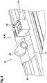
- the wiper blade adapter 14 comprises a pin receiving element 50 (cf. Fig. 8 ).
- the pin receiving element 50 is designed as a socket.
- the pin receiving element 50 is provided to form a fluid connection for supplying the wiper blade device 10 with the wiper fluid line.
- the pin receiving element 50 is designed to receive a fastening element of the wiper arm adapter 54.
- the pin receiving element 50 is provided for a fluid connection for supplying the wiper blade device 10 with the wiping liquid 26.
- the wiper blade adapter 14 has a plug connection 52.
- the plug connection 52 is provided for an electrical power supply.
- the plug connection 52 is formed separately from the pin receiving element 50.
- the plug connection 52 is aligned perpendicular to the connection of the pin receiving element 50.
- the plug connection 52 comprises four plug pins 114 (cf. Fig. 8 ).
- the plug connection 52 is provided for receiving and / or transmitting electrical energy for controlling and / or regulating the heating wire 40.
- the plug connection 52 is provided to receive and / or to pass on electrical energy for a control and / or regulation of the directional valve 38.
- the plug connection 52 is provided for an electrical energy supply for the directional valve 38.
- the wiper arm adapter 54 has a plug connection 104 corresponding to the plug connection 52.
- the plug connection 52 and the corresponding plug connection 104 are coupled to one another for the transmission of electrical energy in an operating state.
- the corresponding plug connection 104 comprises four corresponding plug pins 116 (cf. Fig. 9 )
- the wiper arm adapter 54 has a connecting pin 56 (cf. Fig. 9 ).
- the connecting pin 56 is designed for a fluid connection of the wiper arm adapter 54 to the pin receiving element 50 of the wiper blade adapter 14.
- the connecting pin 56 is formed with a cylindrical outer contour.
- the pin receiving element 50 is adapted to the shape and size of the connecting pin 56.
- the connecting pin 56 comprises a spring element 58.
- the connecting pin 56 is arranged for fastening in a fastening position on the pin receiving element 50.
- the connecting pin 56 can be moved by the spring element 58 from the fastening position into a fixed position.
- the connecting pin 56 is coupled to the pin receiving element 50 in a fixed position. In a fixed position, the connecting pin 56 is coupled to the pin receiving element 50 to form a wiper fluid line.
- the connecting pin 56 has a side connection pin 106.
- the side connector pin 106 is fluidly connected to the wiper fluid line in an assembled state.
- the connecting pin 56 has two rubber rings 108.
- the rubber rings 108 are arranged on the outside of the connecting pin 56.
- the wiper arm adapter 54 has a bent metal spring 110.
- the metal spring 110 is provided for locking the side connection pin 106 in a locking position.
- a pump of the water supply unit guides the wiping liquid 26 out of a wiping liquid reservoir of the water supply unit through the wiper fluid line to the wiper arm adapter 54.
- the wiper fluid line is at least partially arranged in and / or on the wiper arm 20.
- the wiper fluid line is at least partially designed as a flexible line.
- the wiping liquid 26 reaches the connecting pin 56 from the wiping liquid line through the side connection pin 106.
- the connecting pin 56 is fluidly connected to the pin receiving element 50.
- the connecting pin 56 in the pin receiving element 50 is non-positively connected by the rubber rings 108.
- the connecting pin 56 is fixed in the fixed position in the pin receiving element 50 by the spring element 58.
- the side connection pin 106 In the assembled state, the side connection pin 106 is held in the locking position by the bent metal spring 110. In the locking position, the side connection pin 106 is locked in a recess in the bent metal spring 110.
- the plug connection 52 and the corresponding plug connection 104 are coupled to one another.
- the directional valve 38 can be controlled by coupling the plug connection 52 to the corresponding plug connection 104.
- the pin receiving element 50 is fluidly connected to the fluid inlet 102 of the directional valve 38.
- the first wiping liquid supply subchannel 94 or the second wiping liquid supply subchannel 96 is open for carrying out the wiping liquid 26.
- the coil 88 of the directional valve 38 is energized / de-energized or vice versa.
- the coil 88 With a wiping direction 66 upward, the coil 88 is energized. In the event that the coil 88 is energized, the closure element 86 of the directional valve 38 opens the first fluid outlet 90 and blocks the second fluid outlet 92. Alternatively, in the case that the coil 88 is energized, the closure element 86 of the directional valve 38 open the second fluid outlet 92 and block the first fluid outlet 90.
- the wiping liquid 26 reaches the first wiping liquid supply subchannel 94 through the first fluid outlet 90.
- the wiping liquid 26 spreads throughout the first wiping liquid supply subchannel 94.
- the wiping liquid 26 spreads in half of the wind deflector unit 30 (cf. 2 to 4 ).
- the end cap 34 diverts the wiping liquid 26 from the wiping liquid supply channel 22 into the wiping liquid discharge channel 28.
- the end cap 34 diverts the wiping liquid 26 from the first wiping liquid supply subchannel 94 into the wiping liquid discharge channel 28.
- the end cap 34 diverts the wiping liquid 26 from the wiping liquid supply channel 22 into the wiping liquid discharge channel 28 through the return valve 42.
- One end of the wiper fluid discharge channel 28 facing away from the end cap 34 is closed in a fluid-tight manner.
- the wiping liquid 26 spreads throughout the wiping liquid discharge channel 28.
- the wiper liquid 26 flows out of the wiper strip unit 16 through the dispensing elements 24 in the direction of the vehicle window 46.
- the coil 88 With a wiping direction 66 downward, the coil 88 is currentless. In the event that the coil 88 is de-energized, the closure element 86 of the directional valve 38 opens the second fluid outlet 92 and blocks the first fluid outlet 90. Alternatively, in the event that the coil 88 is de-energized, the closure element 86 of the directional valve 38 Block the second fluid outlet 92 and open the first fluid outlet 90.
- the wiping liquid 26 reaches the second wiping liquid supply subchannel 96 through the second fluid outlet 92.
- the wiping liquid 26 spreads throughout the second wiping liquid supply subchannel 96.
- the wiping liquid 26 spreads in half of the wind deflector unit 30 (cf. Fig. 3 ).
- the further end cap 84 guides the wiping liquid 26 from the wiping liquid supply channel 22 into the further wiping liquid discharge channel 80 ⁇ m.
- the further end cap 84 redirects the wiping liquid 26 from the second wiping liquid supply subchannel 96 into the further wiping liquid discharge channel 80.
- the further end cap 84 diverts the wiping liquid 26 from the wiping liquid supply channel 22 into the further wiping liquid discharge channel 80 through the return valve 42.
- An end of the further wiper fluid discharge channel 80 facing away from the further end cap 84 is closed in a fluid-tight manner.
- the wiping liquid 26 spreads in the entire further wiping liquid discharge channel 80.
- the wiping liquid 26 flows out of the wiper strip unit 16 through the dispensing elements 24 in the direction of the vehicle window 46 (cf. 2 to 4 ).
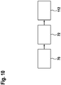
- Figure 10 shows a schematic representation of a method according to the invention. The method is provided for mounting the wiper blade system 60.
- the method has a pre-orientation step 70.
- the pre-orientation step 70 the wiper blade device 10 with the wiper blade 74 and the wiper arm 20 are pre-oriented to one another.
- the wiper blade adapter 14 and the wiper arm adapter 54 are pre-oriented to one another.
- the connecting pin 56 and the pin receiving element 50 are pre-oriented to one another.
- the method has a connection step 72.
- the connecting step 72 the connecting pin 56 is pushed into the pin receiving element 50.
- the connecting pin 56 is fluidly connected to the pin receiving element 50.
- the connecting pin 56 is connected to the pin receiving element 50 in a fluid-tight manner.
- the connecting pin 56 is non-positively connected to the pin receiving element 50 by means of the rubber rings 108.
- the side connection pin 106 is brought into the locking position by means of the metal spring 110.
- the side connection pin 106 is locked by means of the metal spring 110.
- wiper arm adapter 54 and wiper blade adapter 14 are partially coupled to one another.
- the method has a further connection step 112.
- the plug connection 52 and the corresponding plug connection 104 are coupled to one another.
- the plug connection 52 and the corresponding plug connection 104 are electrically coupled to one another.
- the plug connection 52 and the corresponding plug connection 104 are coupled in a form-fitting manner.
- the plug connection 52 and the corresponding plug connection 104 are coupled to one another by a rotational movement of the wiper arm adapter 54 with respect to the wiper blade 74 and / or by a rotational movement of the wiper blade 74 with respect to the wiper arm adapter 54.
- wiper arm adapter 54 and wiper blade adapter 14 are partially coupled to one another.
- connection step 72 and the further connection step 112 the wiper arm adapter 54 and the wiper blade adapter 14 are coupled to one another.
- the wiper blade device 10 and / or the wiper blade 74 and the wiper arm 20 are coupled to one another in terms of fluid technology.
- the wiper blade device 10 and / or the wiper blade 74 and the wiper arm 20 are mechanically coupled to one another.
Landscapes
- Engineering & Computer Science (AREA)
- Mechanical Engineering (AREA)
- Water Supply & Treatment (AREA)
- Ink Jet (AREA)
Applications Claiming Priority (1)
| Application Number | Priority Date | Filing Date | Title |
|---|---|---|---|
| DE102018251766.5A DE102018251766A1 (de) | 2018-12-28 | 2018-12-28 | Wischblattvorrichtung |
Publications (2)
| Publication Number | Publication Date |
|---|---|
| EP3674150A1 true EP3674150A1 (fr) | 2020-07-01 |
| EP3674150B1 EP3674150B1 (fr) | 2021-08-18 |
Family
ID=69005281
Family Applications (1)
| Application Number | Title | Priority Date | Filing Date |
|---|---|---|---|
| EP19218770.6A Active EP3674150B1 (fr) | 2018-12-28 | 2019-12-20 | Dispositif de lame d'essuie-glace |
Country Status (2)
| Country | Link |
|---|---|
| EP (1) | EP3674150B1 (fr) |
| DE (1) | DE102018251766A1 (fr) |
Cited By (3)
| Publication number | Priority date | Publication date | Assignee | Title |
|---|---|---|---|---|
| WO2021032336A1 (fr) * | 2019-08-22 | 2021-02-25 | Robert Bosch Gmbh | Dispositif d'essuie-glace et système d'essuie-glace de pare-brise ayant au moins un dispositif d'essuie-glace |
| CN113911072A (zh) * | 2020-07-07 | 2022-01-11 | 罗伯特·博世有限公司 | 用于带有冲洗功能的玻璃刮水器的刮水器装置 |
| WO2022200289A1 (fr) * | 2021-03-23 | 2022-09-29 | Valeo Systèmes d'Essuyage | Déflecteur d'un balai d'essuyage |
Families Citing this family (2)
| Publication number | Priority date | Publication date | Assignee | Title |
|---|---|---|---|---|
| DE102021103869A1 (de) | 2021-02-18 | 2022-08-18 | Bayerische Motoren Werke Aktiengesellschaft | Düsensystem zum Reinigen eines Fahrzeugteils, insbesondere einer Scheibe eines Kraftfahrzeugs, und Reinigungsverfahren |
| DE102021202656A1 (de) | 2021-03-18 | 2022-11-17 | Continental Automotive Technologies GmbH | Beheizte Reinigungsvorrichtung |
Citations (5)
| Publication number | Priority date | Publication date | Assignee | Title |
|---|---|---|---|---|
| DE3716697A1 (de) * | 1987-05-19 | 1989-01-26 | Igor Groza | Scheibenwischer mit eingebauter wasch- sowie heizvorrichtung |
| US5539951A (en) * | 1995-12-08 | 1996-07-30 | Guell; Ronald R. | Wiper blade assembly including heating and fluid dispensing means |
| DE102009043694A1 (de) * | 2009-10-01 | 2011-04-14 | Valeo Systèmes d'Essuyage | Wischblatt sowie Wischblatt/Wischarm-Kombination |
| EP2368776A1 (fr) * | 2010-03-16 | 2011-09-28 | Valeo Systèmes d'Essuyage | Connecteur hydraulique pour système d'essuie-glace |
| DE102012100777A1 (de) * | 2012-01-31 | 2013-08-01 | Valeo Systèmes d'Essuyage | Wischblatt zum Reinigen von Fahrzeugscheiben |
-
2018
- 2018-12-28 DE DE102018251766.5A patent/DE102018251766A1/de active Pending
-
2019
- 2019-12-20 EP EP19218770.6A patent/EP3674150B1/fr active Active
Patent Citations (5)
| Publication number | Priority date | Publication date | Assignee | Title |
|---|---|---|---|---|
| DE3716697A1 (de) * | 1987-05-19 | 1989-01-26 | Igor Groza | Scheibenwischer mit eingebauter wasch- sowie heizvorrichtung |
| US5539951A (en) * | 1995-12-08 | 1996-07-30 | Guell; Ronald R. | Wiper blade assembly including heating and fluid dispensing means |
| DE102009043694A1 (de) * | 2009-10-01 | 2011-04-14 | Valeo Systèmes d'Essuyage | Wischblatt sowie Wischblatt/Wischarm-Kombination |
| EP2368776A1 (fr) * | 2010-03-16 | 2011-09-28 | Valeo Systèmes d'Essuyage | Connecteur hydraulique pour système d'essuie-glace |
| DE102012100777A1 (de) * | 2012-01-31 | 2013-08-01 | Valeo Systèmes d'Essuyage | Wischblatt zum Reinigen von Fahrzeugscheiben |
Cited By (5)
| Publication number | Priority date | Publication date | Assignee | Title |
|---|---|---|---|---|
| WO2021032336A1 (fr) * | 2019-08-22 | 2021-02-25 | Robert Bosch Gmbh | Dispositif d'essuie-glace et système d'essuie-glace de pare-brise ayant au moins un dispositif d'essuie-glace |
| US11772611B2 (en) | 2019-08-22 | 2023-10-03 | Robert Bosch Gmbh | Wiper device and windscreen wiper system having at least one wiper device |
| CN113911072A (zh) * | 2020-07-07 | 2022-01-11 | 罗伯特·博世有限公司 | 用于带有冲洗功能的玻璃刮水器的刮水器装置 |
| WO2022200289A1 (fr) * | 2021-03-23 | 2022-09-29 | Valeo Systèmes d'Essuyage | Déflecteur d'un balai d'essuyage |
| FR3121102A1 (fr) * | 2021-03-23 | 2022-09-30 | Valeo Systemes D'essuyage | Déflecteur d’un balai d’essuyage. |
Also Published As
| Publication number | Publication date |
|---|---|
| DE102018251766A1 (de) | 2020-07-02 |
| EP3674150B1 (fr) | 2021-08-18 |
Similar Documents
| Publication | Publication Date | Title |
|---|---|---|
| EP3674150B1 (fr) | Dispositif de lame d'essuie-glace | |
| DE19906197B4 (de) | Scheibenwischer mit Spritzdüse und Rückschlagventil | |
| EP3717312B1 (fr) | Dispositif d'aspersion de bras d'essuie-glace | |
| DE102018251742A1 (de) | Wischblattvorrichtung | |
| DE102015113236B4 (de) | Motorkühlsystem | |
| DE102018251763A1 (de) | Wischblattvorrichtung | |
| DE102013209196A1 (de) | Wischvorrichtung | |
| DE102019207610A1 (de) | Wischblattvorrichtung | |
| DE102014201211A1 (de) | Wischvorrichtung | |
| EP3837142B1 (fr) | Dispositif d'essuie-glace | |
| DE102019203145A1 (de) | Wischblattvorrichtung | |
| EP3727957A1 (fr) | Dispositif d'essuie-glace | |
| EP3392097A1 (fr) | Dispositif essuie-glaces | |
| DE102017223526A1 (de) | Wischblattvorrichtung | |
| WO2020136120A1 (fr) | Dispositif formant balai d'essuie-glace | |
| DE102019207611A1 (de) | Wischblattvorrichtung | |
| EP3802240A1 (fr) | Dispositif essuie-glace | |
| EP2962911B1 (fr) | Dispositif de balai d'essuie-glace | |
| DE102021210125A1 (de) | Wischervorrichtung, Wischarmadapter, Verfahren zur Montage einer Wischervorrichtung und Verfahren zum Betreiben einer Wischervorrichtung | |
| DE102020200344A1 (de) | Wischblattvorrichtung | |
| DE102004036037B4 (de) | Kraftfahrzeug | |
| DE102018212055A1 (de) | Wischervorrichtung | |
| EP3392098A1 (fr) | Dispositif d'essuie-glaces | |
| EP3902711B1 (fr) | Dispositif formant balai d'essuie-glace | |
| DE102022200496A1 (de) | Wischblattvorrichtung und Scheibenwischer |
Legal Events
| Date | Code | Title | Description |
|---|---|---|---|
| PUAI | Public reference made under article 153(3) epc to a published international application that has entered the european phase |
Free format text: ORIGINAL CODE: 0009012 |
|
| STAA | Information on the status of an ep patent application or granted ep patent |
Free format text: STATUS: THE APPLICATION HAS BEEN PUBLISHED |
|
| AK | Designated contracting states |
Kind code of ref document: A1 Designated state(s): AL AT BE BG CH CY CZ DE DK EE ES FI FR GB GR HR HU IE IS IT LI LT LU LV MC MK MT NL NO PL PT RO RS SE SI SK SM TR |
|
| AX | Request for extension of the european patent |
Extension state: BA ME |
|
| STAA | Information on the status of an ep patent application or granted ep patent |
Free format text: STATUS: REQUEST FOR EXAMINATION WAS MADE |
|
| 17P | Request for examination filed |
Effective date: 20210111 |
|
| RBV | Designated contracting states (corrected) |
Designated state(s): AL AT BE BG CH CY CZ DE DK EE ES FI FR GB GR HR HU IE IS IT LI LT LU LV MC MK MT NL NO PL PT RO RS SE SI SK SM TR |
|
| GRAP | Despatch of communication of intention to grant a patent |
Free format text: ORIGINAL CODE: EPIDOSNIGR1 |
|
| STAA | Information on the status of an ep patent application or granted ep patent |
Free format text: STATUS: GRANT OF PATENT IS INTENDED |
|
| INTG | Intention to grant announced |
Effective date: 20210602 |
|
| GRAS | Grant fee paid |
Free format text: ORIGINAL CODE: EPIDOSNIGR3 |
|
| GRAA | (expected) grant |
Free format text: ORIGINAL CODE: 0009210 |
|
| STAA | Information on the status of an ep patent application or granted ep patent |
Free format text: STATUS: THE PATENT HAS BEEN GRANTED |
|
| AK | Designated contracting states |
Kind code of ref document: B1 Designated state(s): AL AT BE BG CH CY CZ DE DK EE ES FI FR GB GR HR HU IE IS IT LI LT LU LV MC MK MT NL NO PL PT RO RS SE SI SK SM TR |
|
| REG | Reference to a national code |
Ref country code: GB Ref legal event code: FG4D Free format text: NOT ENGLISH |
|
| REG | Reference to a national code |
Ref country code: CH Ref legal event code: EP |
|
| REG | Reference to a national code |
Ref country code: DE Ref legal event code: R096 Ref document number: 502019002082 Country of ref document: DE |
|
| REG | Reference to a national code |
Ref country code: IE Ref legal event code: FG4D Free format text: LANGUAGE OF EP DOCUMENT: GERMAN Ref country code: AT Ref legal event code: REF Ref document number: 1421376 Country of ref document: AT Kind code of ref document: T Effective date: 20210915 |
|
| REG | Reference to a national code |
Ref country code: LT Ref legal event code: MG9D |
|
| REG | Reference to a national code |
Ref country code: NL Ref legal event code: MP Effective date: 20210818 |
|
| PG25 | Lapsed in a contracting state [announced via postgrant information from national office to epo] |
Ref country code: RS Free format text: LAPSE BECAUSE OF FAILURE TO SUBMIT A TRANSLATION OF THE DESCRIPTION OR TO PAY THE FEE WITHIN THE PRESCRIBED TIME-LIMIT Effective date: 20210818 Ref country code: SE Free format text: LAPSE BECAUSE OF FAILURE TO SUBMIT A TRANSLATION OF THE DESCRIPTION OR TO PAY THE FEE WITHIN THE PRESCRIBED TIME-LIMIT Effective date: 20210818 Ref country code: ES Free format text: LAPSE BECAUSE OF FAILURE TO SUBMIT A TRANSLATION OF THE DESCRIPTION OR TO PAY THE FEE WITHIN THE PRESCRIBED TIME-LIMIT Effective date: 20210818 Ref country code: FI Free format text: LAPSE BECAUSE OF FAILURE TO SUBMIT A TRANSLATION OF THE DESCRIPTION OR TO PAY THE FEE WITHIN THE PRESCRIBED TIME-LIMIT Effective date: 20210818 Ref country code: HR Free format text: LAPSE BECAUSE OF FAILURE TO SUBMIT A TRANSLATION OF THE DESCRIPTION OR TO PAY THE FEE WITHIN THE PRESCRIBED TIME-LIMIT Effective date: 20210818 Ref country code: PT Free format text: LAPSE BECAUSE OF FAILURE TO SUBMIT A TRANSLATION OF THE DESCRIPTION OR TO PAY THE FEE WITHIN THE PRESCRIBED TIME-LIMIT Effective date: 20211220 Ref country code: NO Free format text: LAPSE BECAUSE OF FAILURE TO SUBMIT A TRANSLATION OF THE DESCRIPTION OR TO PAY THE FEE WITHIN THE PRESCRIBED TIME-LIMIT Effective date: 20211118 Ref country code: BG Free format text: LAPSE BECAUSE OF FAILURE TO SUBMIT A TRANSLATION OF THE DESCRIPTION OR TO PAY THE FEE WITHIN THE PRESCRIBED TIME-LIMIT Effective date: 20211118 Ref country code: LT Free format text: LAPSE BECAUSE OF FAILURE TO SUBMIT A TRANSLATION OF THE DESCRIPTION OR TO PAY THE FEE WITHIN THE PRESCRIBED TIME-LIMIT Effective date: 20210818 |
|
| PG25 | Lapsed in a contracting state [announced via postgrant information from national office to epo] |
Ref country code: PL Free format text: LAPSE BECAUSE OF FAILURE TO SUBMIT A TRANSLATION OF THE DESCRIPTION OR TO PAY THE FEE WITHIN THE PRESCRIBED TIME-LIMIT Effective date: 20210818 Ref country code: LV Free format text: LAPSE BECAUSE OF FAILURE TO SUBMIT A TRANSLATION OF THE DESCRIPTION OR TO PAY THE FEE WITHIN THE PRESCRIBED TIME-LIMIT Effective date: 20210818 Ref country code: GR Free format text: LAPSE BECAUSE OF FAILURE TO SUBMIT A TRANSLATION OF THE DESCRIPTION OR TO PAY THE FEE WITHIN THE PRESCRIBED TIME-LIMIT Effective date: 20211119 |
|
| PG25 | Lapsed in a contracting state [announced via postgrant information from national office to epo] |
Ref country code: NL Free format text: LAPSE BECAUSE OF FAILURE TO SUBMIT A TRANSLATION OF THE DESCRIPTION OR TO PAY THE FEE WITHIN THE PRESCRIBED TIME-LIMIT Effective date: 20210818 |
|
| PG25 | Lapsed in a contracting state [announced via postgrant information from national office to epo] |
Ref country code: DK Free format text: LAPSE BECAUSE OF FAILURE TO SUBMIT A TRANSLATION OF THE DESCRIPTION OR TO PAY THE FEE WITHIN THE PRESCRIBED TIME-LIMIT Effective date: 20210818 |
|
| REG | Reference to a national code |
Ref country code: DE Ref legal event code: R097 Ref document number: 502019002082 Country of ref document: DE |
|
| PG25 | Lapsed in a contracting state [announced via postgrant information from national office to epo] |
Ref country code: SM Free format text: LAPSE BECAUSE OF FAILURE TO SUBMIT A TRANSLATION OF THE DESCRIPTION OR TO PAY THE FEE WITHIN THE PRESCRIBED TIME-LIMIT Effective date: 20210818 Ref country code: SK Free format text: LAPSE BECAUSE OF FAILURE TO SUBMIT A TRANSLATION OF THE DESCRIPTION OR TO PAY THE FEE WITHIN THE PRESCRIBED TIME-LIMIT Effective date: 20210818 Ref country code: RO Free format text: LAPSE BECAUSE OF FAILURE TO SUBMIT A TRANSLATION OF THE DESCRIPTION OR TO PAY THE FEE WITHIN THE PRESCRIBED TIME-LIMIT Effective date: 20210818 Ref country code: EE Free format text: LAPSE BECAUSE OF FAILURE TO SUBMIT A TRANSLATION OF THE DESCRIPTION OR TO PAY THE FEE WITHIN THE PRESCRIBED TIME-LIMIT Effective date: 20210818 Ref country code: CZ Free format text: LAPSE BECAUSE OF FAILURE TO SUBMIT A TRANSLATION OF THE DESCRIPTION OR TO PAY THE FEE WITHIN THE PRESCRIBED TIME-LIMIT Effective date: 20210818 Ref country code: AL Free format text: LAPSE BECAUSE OF FAILURE TO SUBMIT A TRANSLATION OF THE DESCRIPTION OR TO PAY THE FEE WITHIN THE PRESCRIBED TIME-LIMIT Effective date: 20210818 |
|
| PLBE | No opposition filed within time limit |
Free format text: ORIGINAL CODE: 0009261 |
|
| STAA | Information on the status of an ep patent application or granted ep patent |
Free format text: STATUS: NO OPPOSITION FILED WITHIN TIME LIMIT |
|
| 26N | No opposition filed |
Effective date: 20220519 |
|
| PG25 | Lapsed in a contracting state [announced via postgrant information from national office to epo] |
Ref country code: MC Free format text: LAPSE BECAUSE OF FAILURE TO SUBMIT A TRANSLATION OF THE DESCRIPTION OR TO PAY THE FEE WITHIN THE PRESCRIBED TIME-LIMIT Effective date: 20210818 Ref country code: IT Free format text: LAPSE BECAUSE OF FAILURE TO SUBMIT A TRANSLATION OF THE DESCRIPTION OR TO PAY THE FEE WITHIN THE PRESCRIBED TIME-LIMIT Effective date: 20210818 |
|
| PG25 | Lapsed in a contracting state [announced via postgrant information from national office to epo] |
Ref country code: SI Free format text: LAPSE BECAUSE OF FAILURE TO SUBMIT A TRANSLATION OF THE DESCRIPTION OR TO PAY THE FEE WITHIN THE PRESCRIBED TIME-LIMIT Effective date: 20210818 |
|
| REG | Reference to a national code |
Ref country code: BE Ref legal event code: MM Effective date: 20211231 |
|
| PG25 | Lapsed in a contracting state [announced via postgrant information from national office to epo] |
Ref country code: LU Free format text: LAPSE BECAUSE OF NON-PAYMENT OF DUE FEES Effective date: 20211220 Ref country code: IE Free format text: LAPSE BECAUSE OF NON-PAYMENT OF DUE FEES Effective date: 20211220 |
|
| PG25 | Lapsed in a contracting state [announced via postgrant information from national office to epo] |
Ref country code: BE Free format text: LAPSE BECAUSE OF NON-PAYMENT OF DUE FEES Effective date: 20211231 |
|
| PG25 | Lapsed in a contracting state [announced via postgrant information from national office to epo] |
Ref country code: CY Free format text: LAPSE BECAUSE OF FAILURE TO SUBMIT A TRANSLATION OF THE DESCRIPTION OR TO PAY THE FEE WITHIN THE PRESCRIBED TIME-LIMIT Effective date: 20210818 |
|
| PG25 | Lapsed in a contracting state [announced via postgrant information from national office to epo] |
Ref country code: HU Free format text: LAPSE BECAUSE OF FAILURE TO SUBMIT A TRANSLATION OF THE DESCRIPTION OR TO PAY THE FEE WITHIN THE PRESCRIBED TIME-LIMIT; INVALID AB INITIO Effective date: 20191220 |
|
| REG | Reference to a national code |
Ref country code: CH Ref legal event code: PL |
|
| PG25 | Lapsed in a contracting state [announced via postgrant information from national office to epo] |
Ref country code: LI Free format text: LAPSE BECAUSE OF NON-PAYMENT OF DUE FEES Effective date: 20221231 Ref country code: CH Free format text: LAPSE BECAUSE OF NON-PAYMENT OF DUE FEES Effective date: 20221231 |
|
| PG25 | Lapsed in a contracting state [announced via postgrant information from national office to epo] |
Ref country code: MK Free format text: LAPSE BECAUSE OF FAILURE TO SUBMIT A TRANSLATION OF THE DESCRIPTION OR TO PAY THE FEE WITHIN THE PRESCRIBED TIME-LIMIT Effective date: 20210818 |
|
| GBPC | Gb: european patent ceased through non-payment of renewal fee |
Effective date: 20231220 |
|
| PG25 | Lapsed in a contracting state [announced via postgrant information from national office to epo] |
Ref country code: MT Free format text: LAPSE BECAUSE OF FAILURE TO SUBMIT A TRANSLATION OF THE DESCRIPTION OR TO PAY THE FEE WITHIN THE PRESCRIBED TIME-LIMIT Effective date: 20210818 |
|
| PG25 | Lapsed in a contracting state [announced via postgrant information from national office to epo] |
Ref country code: GB Free format text: LAPSE BECAUSE OF NON-PAYMENT OF DUE FEES Effective date: 20231220 |
|
| PG25 | Lapsed in a contracting state [announced via postgrant information from national office to epo] |
Ref country code: GB Free format text: LAPSE BECAUSE OF NON-PAYMENT OF DUE FEES Effective date: 20231220 |
|
| PG25 | Lapsed in a contracting state [announced via postgrant information from national office to epo] |
Ref country code: TR Free format text: LAPSE BECAUSE OF FAILURE TO SUBMIT A TRANSLATION OF THE DESCRIPTION OR TO PAY THE FEE WITHIN THE PRESCRIBED TIME-LIMIT Effective date: 20210818 |
|
| PGFP | Annual fee paid to national office [announced via postgrant information from national office to epo] |
Ref country code: FR Payment date: 20251218 Year of fee payment: 7 |
|
| REG | Reference to a national code |
Ref country code: AT Ref legal event code: MM01 Ref document number: 1421376 Country of ref document: AT Kind code of ref document: T Effective date: 20241220 |
|
| PGFP | Annual fee paid to national office [announced via postgrant information from national office to epo] |
Ref country code: DE Payment date: 20260223 Year of fee payment: 7 |
|
| PG25 | Lapsed in a contracting state [announced via postgrant information from national office to epo] |
Ref country code: AT Free format text: LAPSE BECAUSE OF NON-PAYMENT OF DUE FEES Effective date: 20241220 |
|
| PGFP | Annual fee paid to national office [announced via postgrant information from national office to epo] |
Ref country code: AT Payment date: 20260410 Year of fee payment: 5 |