EP3674211B1 - Wandelbares flugzeug und zugehöriges steuerungsverfahren - Google Patents
Wandelbares flugzeug und zugehöriges steuerungsverfahren Download PDFInfo
- Publication number
- EP3674211B1 EP3674211B1 EP18248242.2A EP18248242A EP3674211B1 EP 3674211 B1 EP3674211 B1 EP 3674211B1 EP 18248242 A EP18248242 A EP 18248242A EP 3674211 B1 EP3674211 B1 EP 3674211B1
- Authority
- EP
- European Patent Office
- Prior art keywords
- convertiplane
- appendage
- wing
- axis
- configuration
- Prior art date
- Legal status (The legal status is an assumption and is not a legal conclusion. Google has not performed a legal analysis and makes no representation as to the accuracy of the status listed.)
- Active
Links
Images




Classifications
-
- B—PERFORMING OPERATIONS; TRANSPORTING
- B64—AIRCRAFT; AVIATION; COSMONAUTICS
- B64C—AEROPLANES; HELICOPTERS
- B64C27/00—Rotorcraft; Rotors peculiar thereto
- B64C27/22—Compound rotorcraft, i.e. aircraft using in flight the features of both aeroplane and rotorcraft
- B64C27/28—Compound rotorcraft, i.e. aircraft using in flight the features of both aeroplane and rotorcraft with forward-propulsion propellers pivotable to act as lifting rotors
-
- B—PERFORMING OPERATIONS; TRANSPORTING
- B64—AIRCRAFT; AVIATION; COSMONAUTICS
- B64C—AEROPLANES; HELICOPTERS
- B64C29/00—Aircraft capable of landing or taking-off vertically, e.g. vertical take-off and landing [VTOL] aircraft
- B64C29/0008—Aircraft capable of landing or taking-off vertically, e.g. vertical take-off and landing [VTOL] aircraft having its flight directional axis horizontal when grounded
- B64C29/0016—Aircraft capable of landing or taking-off vertically, e.g. vertical take-off and landing [VTOL] aircraft having its flight directional axis horizontal when grounded the lift during taking-off being created by free or ducted propellers or by blowers
- B64C29/0033—Aircraft capable of landing or taking-off vertically, e.g. vertical take-off and landing [VTOL] aircraft having its flight directional axis horizontal when grounded the lift during taking-off being created by free or ducted propellers or by blowers the propellers being tiltable relative to the fuselage
-
- B—PERFORMING OPERATIONS; TRANSPORTING
- B64—AIRCRAFT; AVIATION; COSMONAUTICS
- B64C—AEROPLANES; HELICOPTERS
- B64C9/00—Adjustable control surfaces or members, e.g. rudders
- B64C9/04—Adjustable control surfaces or members, e.g. rudders with compound dependent movements
-
- B—PERFORMING OPERATIONS; TRANSPORTING
- B64—AIRCRAFT; AVIATION; COSMONAUTICS
- B64C—AEROPLANES; HELICOPTERS
- B64C9/00—Adjustable control surfaces or members, e.g. rudders
- B64C9/14—Adjustable control surfaces or members, e.g. rudders forming slots
- B64C9/16—Adjustable control surfaces or members, e.g. rudders forming slots at the rear of the wing
- B64C9/18—Adjustable control surfaces or members, e.g. rudders forming slots at the rear of the wing by single flaps
-
- B—PERFORMING OPERATIONS; TRANSPORTING
- B64—AIRCRAFT; AVIATION; COSMONAUTICS
- B64C—AEROPLANES; HELICOPTERS
- B64C9/00—Adjustable control surfaces or members, e.g. rudders
- B64C2009/005—Ailerons
Definitions
- the present invention relates to a convertiplane and a related method of control.
- aeroplanes are normally used for high cruising speeds, in particular above 150 knots and at high altitudes, for example above 30,000 feet.
- aeroplanes use fixed wings to generate the lift necessary for sustaining the aeroplane in the air.
- a sufficient amount of lift can only be achieved by accelerating the aeroplane on quite long runways. These runways are also needed to allow aeroplanes to land.
- helicopters generate the necessary lift through rotation of the main rotor's blades. Consequently, helicopters can take-off/land without the need for horizontal speed and using particularly small areas. Moreover, helicopters are capable of hovering and of flying at relatively low altitudes and speeds, thereby being particularly easy to handle and adapted for demanding manoeuvres, such as mountain or sea rescue operations.
- helicopters have intrinsic limits regarding the maximum operating altitude, which is around 20,000 feet and the maximum operating speed, which cannot exceed 150 knots.
- convertiplanes are known.
- convertiplanes basically comprise:
- the rotors are tiltable with respect to the associated engines and nacelles and the associated wing about a related fourth axis parallel to the second axis.
- Convertiplanes are also able to selectively assume:
- convertiplanes Due to the possibility of tilting the rotors, convertiplanes are able to take off and land like a helicopter, i.e. in a direction substantially perpendicular to the first longitudinal axis of the convertiplane, without the need of a runway.
- convertiplanes are also able to take off and land on rough terrain and without generating noise levels incompatible with urban areas.
- convertiplanes are capable of hovering when arranged in the helicopter configuration.
- Convertiplanes can also reach and maintain cruising speeds of approximately 250-300 knots and flight altitudes in the order of 30,000 feet when arranged in the aeroplane configuration.
- This cruising speed is much higher than the roughly 150 knots defining the maximum cruising speed for helicopters.
- the aforementioned altitude is much higher than that typical of helicopters and enables convertiplanes arranged in the aeroplane configuration to avoid the clouds and atmospheric disturbances characteristic of lower altitudes.
- the wings of the aircraft each comprise a wing box connected to the fuselage in a fixed manner and movable appendages.
- movable appendages are hinged to the main body so as to define respective trailing edges of the corresponding wings.
- Ailerons and flaps constitute examples of these movable appendages.
- Ailerons are adapted to control the aircraft's roll, i.e. the inclination of the aircraft about a longitudinal axis of the fuselage.
- ailerons are tilted in mutually opposite directions with respect to the fuselage, so as to increase the lift of one wing and reduce the lift of the other wing.
- flaps are both tilted in the same direction, so as to increase or reduce the overall lift generated by the wings.
- Flaperons act like flaps, i.e. reduce or increase the lift generated by the wings, in the aircraft's take-off or landing phase.
- Flaperons act like ailerons, i.e. reduce the lift of one wing and increase the lift of the other wing, when it is necessary for the aircraft to perform a roll manoeuvre.
- each aperture between the trailing edge of the wings and the movable appendages causes a substantial increase in the overall resistance generated by the aircraft's wings, with negative consequences on the aircraft's payload and performance.
- US 5,094,412 describes a convertiplane equipped with flaperons.
- Each flaperon comprises an associated leading edge hinged to a trailing edge of the associated wing.
- this convertiplane also comprises a sealing element interposed between the respective wing and the corresponding flaperon, which is adapted to close the aperture between them when the corresponding flaperon is operated.
- the convertiplane comprises a connecting structure for each wing configured so as to arrange the associated sealing element in a closing position of the aforementioned aperture, for predetermined angular positions of the flaperon when the flaperon is operated.
- Each wing also comprises an end spar arranged at the side of an associated trailing edge and having a flat section in a plane orthogonal to the wing's direction of extension.
- sealing elements define additional elements, which require specific space occupation and dedicated connection structures.
- XP055391132 discloses a tilt-rotor demonstrator.
- US-A-2017/305565 discloses a propulsion system for a tiltrotor aircraft with an engine supported by the airframe and a fixed gearbox operably coupled to the engine.
- Inboard and outboard pedestals are supported by the airframe and positioned above the wing.
- a pylon assembly is rotatably coupled between the inboard and outboard pedestals.
- the pylon assembly includes a spindle gearbox having an input gear, a mast operably coupled to the input gear and a proprotor assembly operable to rotate with the mast.
- the spindle gearbox is rotatable about a conversion axis to selectively operate the tiltrotor aircraft between helicopter and airplane modes.
- a common shaft rotatable about the conversion axis, is configured to transfer torque from an output gear of the fixed gearbox to the input gear of the spindle gearbox.
- Each of the inboard and outboard pedestals includes a journal bearing that provides a stiff coupling with the pylon assembly.
- US-A-2018/305037 discloses a fuel system for an aircraft.
- the fuel system includes fuel cell having a plurality of sides including a first side and at least one deformable clip having a secured end and a free end.
- the secured end is coupled to the first side of the fuel cell and the free end overlapping the airframe of the aircraft such that the first side of the fuel cell is positioned adjacent to the airframe.
- the at least one deformable clip is deformable to allow the fuel cell to move independently of the airframe in response to an impact of the aircraft, thereby protecting the fuel cell from damage resulting from the impact.
- FR-A-2791634 discloses a tilt wing aircraft.
- the aircraft has a nacelle with a front section which tilts with the rotor and a fixed rear section receiving the engine.
- the front tilting section has a lower cowling, which is extended at the rear, in the aircraft mode, by a re-curved cap.
- the cap provides a smooth flow surface when the engine is in helicopter mode.
- the object of the present invention is the embodiment of a convertiplane that enables satisfying at least one of the above-specified needs in a simple and inexpensive manner.
- the present invention also relates to a method of controlling a convertiplane as claimed in claim 12.
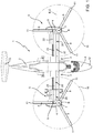
- reference numeral 1 indicates an aircraft, in particular a convertiplane.
- the convertiplane 1 basically comprises:
- the fuselage 2 also comprises a nose 12 arranged at the front and a tail portion 13, opposite to each other along axis A.
- the free edges 9 of the respective wings 3 opposite to the fuselage 2 are aligned along an axis E orthogonal to axis A.
- each rotor 5 basically comprises:
- the rotors 5 are tiltable about an axis C with respect to the associated wings 3 and the associated nacelles 4.
- Axis C is transversal to axis A and axes B.
- Axis C is also parallel to axis E.
- the convertiplane 1 can be selectively arranged:
- the blades 8 extend along respective axes and comprise respective free tips 11.
- the free tips 11 of the blades 8 of the rotor 5 trace an imaginary circumference indicated hereinafter in this description as the rotor disc 10.
- the wing 3 comprises:
- the rotor 5 is arranged at the edge 9 of the wing 3.
- the movable appendages 21 and 22 are arranged one after the other along the axis E, proceeding from the fuselage 2 towards the rotor 5.
- the movable appendages 21 and 22 are arranged below the rotor 5.
- the movable appendages 21 and 22 are arranged inside the ideal cylinder obtained by extending the rotor disc 10 parallel to axis B.
- movable appendage 21 is arranged below the rotor disc 10, i.e. in the area where the blades 8 have the maximum tangential speed and where the effect of the downwash generated by the rotor 5 is greater.
- the wing box 20 comprises ( Figure 7 ):
- the covering 27 defines:
- the appendages 21 and 22 are arranged on the side of the trailing edge 30 of the wing box 20.
- Each appendage 21, 22 defines a respective wing profile 35, 36 and, in turn, comprises:
- Appendage 22 is hinged to the wing box 20 parallel to axis E.
- appendage 22 is normally arranged in a neutral position, shown in Figure 2 , where the top surface 46 and bottom surface 48 define respective extensions of the top surface 31 and bottom surface 32 of the wing box 20. Furthermore, appendage 22 is selectively movable from the neutral position to a first raised operating position and a second lowered operating position.
- appendages 22 can be selectively arranged in respective third operating positions, interposed between the respective neutral positions and first raised operating positions, when the convertiplane 1 exceeds a certain cruising speed, so as to define air brakes.
- the angle between the neutral position and the first raised operating position is 30 degrees.
- the angle between the neutral position and the second lowered operating position is 30 degrees.
- the angle between the neutral position and the third raised operating position is approximately 5 degrees.
- the angle ⁇ of movement of appendage 22 between the fourth lowered position and the neutral position is variable according to the forward speed on the convertiplane 1 in "helicopter" mode.
- the maximum angle ⁇ of the aforementioned movement is greater than the angle defined by appendage 22 between the second lowered operating position and the neutral position and, in the case shown, is equal to 70 degrees.
- this movement takes place when the forward speed of the convertiplane 1 drops below a threshold value.
- appendage 21 is hinged to the wing box 20 and is selectively movable between:
- the wing profiles 35 and 28 are contiguous with one another, and the portion of top surface 45 and bottom surface 47 adjacent to the trailing edge 43 define respective extensions of the top surface 31 and of the bottom surface 32 of the wing box 20.
- the spar 26a is curved in a plane orthogonal to axis E and wall 41 of appendage 21 is arranged abutting its entire length against spar 26a when appendage 21 is in the first neutral position.
- the top surface 45 of appendage 21 defines an extension of spar 26a when appendage 21 is in the second lowered operating position ( Figure 4 ).
- the opening 50 is open on the side opposite to the leading edge 29 and delimited by two mutually consecutive ribs 25b and a section 53 of spar 26a extending between the ribs 25b.
- the trailing edge 30 of the wing box 20 is interrupted at this opening 50.
- Appendage 21 is at least partly housed inside the opening 50 when it is arranged in the first neutral position ( Figure 5 ).
- wall 41 and the portions of top surface 45 and bottom surface 47 adjacent to wall 41 are housed inside the opening 50 when appendage 21 is arranged in the first neutral position.
- Wall 41 also has a curvature facing trailing edge 43, proceeding from top surface 45 towards the bottom surface 47 in a section obtained in a plane orthogonal to axis E.
- the trailing edge of the wing 3 is defined by the trailing edge 30 of the wing box 20 and by the trailing edge 44 of appendage 22 between ribs 25a and 25b, and by the trailing edge 43 of appendage 21 between ribs 25b.
- wing box 20 defines:
- Compartment 51 defines a portion of a fuel tank.
- Compartment 52 houses an interconnection shaft 55, which connects the rotors 5 to each other.
- spar 26a has a C-shaped section and spars 26b and 26c have an I-shaped section in a plane orthogonal to axis E.
- spar 26a has a curvature facing the trailing edge 30 in a plane orthogonal to axis E, proceeding from the top surface 31 to the bottom surface 32 of the wing box 20.
- the convertiplane 1 further comprises:
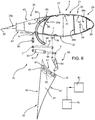
- actuating mechanisms 75 are arranged on respective mutually opposite side edges of appendage 21, as shown in Figure 8 .
- Each actuating mechanism 75 comprises:
- the actuator 81 comprises a sleeve 93 and a piston 94, sliding with respect to the sleeve 93.
- axes F, G, H and I are parallel to one another and parallel to axis E.
- each actuating mechanism 75 is arranged on respective brackets 77 and 76 fixed to the respective rib 25b.
- Each actuating mechanism 75 further comprises:
- the roller 83 slides inside the slot 84 following the movement of appendage 21 from the second lowered position to the first neutral position.
- the wing box 20 further comprises a pair of stop elements 85 defining respective seats 86 engaged by corresponding projections 87 carried by respective arms 82, when appendage 21 is in the first position.
- each projection 87 extends from the roller 83 in a direction transversal to the associated arm 82.
- Each actuating mechanism 75 further comprises:
- Axes J are parallel to respective axes F, G, H and I.
- the levers 80 of the actuating mechanisms 75 are connected to each other by a rod 92 (shown in Figure 8 ), so as to ensure the correct movement of appendage 21 in the event of one of the actuating mechanisms 75 failing.
- the actuator 81 and the lever 80 of each actuating mechanism 75 lie on respective planes orthogonal to axis E, parallel to and spaced apart from each other.
- each actuating mechanism 75 The hinge between the actuator 81 and the lever 80 about axis I of each actuating mechanism 75 is obtained via an associated pin 89 ( Figure 8 ) extending along the corresponding axis I and connected to the respective actuator 81 and lever 80.
- each actuating mechanism 75 is interposed between the corresponding actuator 81 and lever 80 along the corresponding axis E.
- each actuating mechanism 75 is open on the side of the associated arm 82 and is defined by the associated rib 25b.
- Each slot 84 extends from the associated seat 86 defined by the top surface 31 of the wing box 20 up to a free end 88 arranged below the bottom surface 32 of the wing box 20.
- each slot 84 has a curvature facing the trailing edge 30 in a plane orthogonal to axis E, proceeding from the associated seat 86 to the associated end 88.
- each actuating mechanism 75 is interposed between the respective rods 91 along the corresponding axis E.
- the axes of extension of the actuator 81, lever 80 and rods 91 of each actuating mechanism 75 are substantially parallel to one another.
- axes G are arranged below, in a plane orthogonal to axis E, at the free ends 88 opposite to the stop elements 85 of the respective slots 84.
- axes G and arms 82 are preferably arranged below ends 88 in a plane orthogonal to axis E.
- the wing 3 also comprises a fairing 95 (only schematically shown in Figures 4 and 5 ) housing the actuating mechanism 75 when appendage 21 is in the first neutral position, to limit its effect on the aerodynamics of the convertiplane 1.
- This fairing 95 is opportunely configured to allow the lowering of appendage 21 and the movement of the actuating mechanisms 75, when appendage 21 moves between the first neutral position and the second lowered operating position.
- appendages 21 can be selectively arranged in respective third raised operating positions (not shown) when the convertiplane 1 is in the aeroplane configuration, so as to define air brakes.
- Each first neutral position of appendages 21 is angularly interposed between the respective second lowered operating position and the respective third raised operating position.
- convertiplane 1 The functioning of the convertiplane 1 is described below in detail, starting from the "aeroplane" configuration of the convertiplane 1 shown in Figure 1 ( Figure 2 ) and with reference to a single wing 3.
- axis B of the rotor 5 is parallel to axis A and orthogonal to axis C.
- appendage 21 is arranged in the first neutral position and appendage 22 is controlled like a flaperon.
- appendage 21 defines an extension of the wing box 20.
- actuating mechanism 75 is housed inside the fairing 95.
- appendage 22 is normally arranged in the neutral position, shown in Figure 2 , and is selectively movable to the first raised operating position or the second lowered operating position.
- both appendages 22 are arranged in the respective first raised operating positions or second lowered operating positions. In these conditions, appendages 22 act like flaps. Contrariwise, if it is necessary to generate a roll moment directed about axis A on the convertiplane 1, one of appendages 22 is arranged in the first raised position and the other appendage 22 is arranged in the second lowered position. In these conditions, appendages 22 behave like traditional ailerons.
- appendages 21 and 22 are selectively arranged in the respective third raised operating positions, where they define air brakes.
- rotors 5 are turned 90 degrees towards the tail portion 13 of the fuselage 2 about axis C.
- axes B are orthogonal to axis A and axis C ( Figure 1 ).
- the opening 50 of the wing box 20 is arranged below the rotor disc 10, i.e. in the area where this downwash generated by the rotor 5 is more intense.
- appendage 21 is arranged in the second lowered operating position and appendage 22 is arranged in the fourth lowered position.
- This airflow also flows through the opening delimited by the wing 3 and left free by appendage 22 arranged in the fourth lowered position.
- the control unit 70 moves appendage 21 between the first neutral position and the second lowered operating position via actuating mechanism 75. Similarly, the control unit 70 moves appendage 22 between the neutral position, the first raised operating position, the second lowered operating position, the third raised position and the fourth lowered position, via an actuating mechanism not shown and not forming part of the present invention.
- control unit 70 moves appendage 21 from the first neutral position ( Figure 5 ) to the second lowered operating position ( Figure 4 ) and appendage 22 to the fourth lowered operating position.
- each actuating mechanism 75 engages the seat 86 and the lever 80 is arranged substantially parallel to actuator 81 and the connecting rod 90.
- control unit 70 controls the extension of the piston 94 of each actuator 81 in relation to the respective sleeve 93. This causes the rotation of the levers 80 about axis F in the anticlockwise direction, with reference to Figure 4 , and the consequent rotation of wall 41 and appendage 21 about the movable axis G in the anticlockwise direction.
- control unit 70 controls, starting from the condition in Figure 4 , the sliding of the pistons 94 inside the sleeves 93 of the respective actuator 81. This causes the rotation of the levers 80 about axis F in the clockwise direction, with reference to Figure 4 , and the consequent rotation of wall 41 and appendage 21 about the movable axis G in the clockwise direction.
- rollers 83 advance in a clockwise direction inside the respective slots 84 until engaging the respective stop elements 85.
- appendage 21 is in the first neutral position, as shown Figure 5 .
- Rod 92 ensures the correct movement of the levers 80 in the event of one of the actuators 81 failing.
- appendage 21 passes through the gap between the adjacent fairings 95 when set in the second lowered operating position.
- Wing 3' is similar to wing 3 and will be described hereinafter only with regard to the differences; where possible, the same or equivalent parts of wings 3 and 3' will be indicated with the same reference numerals.
- wing 3' differs from wing 3 in that appendage 21' extends up to the nacelle 4 and in that appendage 22' is arranged within appendage 21' in a position close to the nacelle 4.
- appendage 21, 21' is selectively movable between:
- top surface 45 of appendage 21 defines an extension of spar 26a when appendage 21 is in the second lowered operating position and the convertiplane 1 is in the "helicopter" configuration.
- this effect enables reducing the necessary diameter of the rotor 5 and being able to increase the chord of the wing 3 with respect to known solutions, where the size of the wing 3 along axis A is limited so as not to excessively interfere with this downwash generated by the rotor 5 when the convertiplane 1 is in the "helicopter" configuration.
- wall 41 could be arranged abutting against spar 26a for a limited part of its length, for example only at the top surface 31 and the bottom surface 32.
Landscapes
- Engineering & Computer Science (AREA)
- Aviation & Aerospace Engineering (AREA)
- Chemical & Material Sciences (AREA)
- Combustion & Propulsion (AREA)
- Mechanical Engineering (AREA)
- Toys (AREA)
- Transmission Devices (AREA)
- Turbine Rotor Nozzle Sealing (AREA)
Claims (15)
- Wandelflugzeug (1), das Folgendes umfasst:- einen Flugzeugrumpf (2), der sich entlang einer ersten Achse (A) erstreckt;- ein Paar Auslegerflügel (3, 3'), die von den jeweiligen Seiten des Flugzeugrumpfs (2) abstehen;- ein Paar Gondeln (4), die die jeweiligen Triebwerke aufnehmen und bezüglich der Flügel (3, 3') befestigt sind; und- ein Paar Rotoren (5), die den Flügeln (3, 3') zugeordnet sind, die um die jeweiligen zweiten Achsen (B) gedreht werden können, und um eine dritte Achse (C), die senkrecht zu der ersten Achse (A) und der jeweiligen zweiten Achse (B) ist, gekippt werden können zwischen:einer ersten Position, wobei die zweiten Achsen (B) parallel zu der ersten Achse (A) sind, die dann erreicht wird, wenn sich das Wandelflugzeug (1) in einer Tragflüglerkonfiguration befindet; undeiner zweiten Position, wobei die zweiten Achsen (B) senkrecht zu der ersten Achse (A) und zu der dritten Achse (C) sind, die dann erreicht wird, wenn sich das Wandelflugzeug (1) in einer Drehflüglerkonfiguration befindet;wobei jeder Flügel (3, 3') ferner einen Flügelkasten und einen ersten beweglichen Anhang (22, 22'), der schwenkbar an dem Flügelkasten (20) angebracht ist, umfasst;
wobei jeder erste Anhang (22, 22') bezüglich des Flügelkastens (20) dann, wenn sich das Wandelflugzeug (1) in der Tragflüglerkonfiguration befindet, bewegt werden kann zwischen:- einer jeweiligen ersten neutralen Position, der ein erster Hubwert des jeweiligen Flügels (3, 3') zugeordnet ist;- einer jeweiligen zweiten angehobenen Betriebsposition, der ein zweiter Hubwert des jeweiligen Flügels (3, 3'), der kleiner ist als der erste Hubwert, zugeordnet ist; und- einer jeweiligen dritten abgesenkten Betriebsposition, der ein dritter Hubwert des jeweiligen Flügels (3, 3'), der größer ist als der erste Hubwert, zugeordnet ist;dadurch gekennzeichnet, dass jeder Flügel (3, 3') ferner einen zweiten Anhang (21, 21') umfasst, der gelenkig an dem Flügelkasten (20) angebracht ist und selektiv bewegt werden kann zwischen:- einer jeweiligen ersten neutralen Position, die angenommen wird, wenn sich das Wandelflugzeug (1) in der Tragflüglerkonfiguration befindet, und in der es eine Verlängerung des Flügelkastens (20) definiert; und- einer jeweiligen zweiten Position, die angenommen wird, wenn sich das Wandelflugzeug (1) in der Drehflüglerkonfiguration befindet, und in der es mit dem Flügelkasten (20) eine Öffnung (50) definiert, durch die der Abwind, der durch den jeweiligen Rotor (5) erzeugt wird, passieren kann. - Wandelflugzeug nach Anspruch 1, dadurch gekennzeichnet, dass die Bewegung jedes zweiten Anhangs (21, 21') von der jeweiligen ersten Position zu der jeweiligen zweiten Position im Betrieb durch den Übergang des Wandelflugzeugs (1) von der Tragflüglerkonfiguration in die Drehflüglerkonfiguration und umgekehrt veranlasst wird.
- Wandelflugzeug nach Anspruch 1 oder 2, dadurch gekennzeichnet, dass jeder zweite Anhang (21, 21') ein Flügelprofil (35) definiert, das eine Stirnwand (41) und eine erste Hinterkante (43) umfasst, die einander gegenüber liegen;
wobei der Flügelkasten (20) des jeweiligen Flügels (3, 3') wiederum eine erste Vorderkante (29), einen Holm (26a), der einen gekrümmten Abschnitt in einem Abschnitt, der senkrecht zu einer vierten Achse (E) der Verlängerung des jeweiligen Flügels (3) ist, aufweist, eine erste obere Oberfläche (33) und eine erste untere Oberfläche (32), die einander gegenüberliegen und zu der Vorderkante (29) konvergieren, umfasst;
wobei die Stirnwand (41) gekrümmt ist und so angeordnet ist, dass sie zumindest an der ersten oberen Oberfläche (31) und der ersten unteren Oberfläche (32) an dem Holm (26a) anliegt, wenn sich der erste bewegliche Anhang (22, 22') in der ersten Position befindet. - Flügel nach Anspruch 2 oder 3, dadurch gekennzeichnet, dass jeder zweite Anhang (21, 21') eine zweite untere Oberfläche (47) und eine zweite obere Oberfläche (45) umfasst, die einander gegenüber liegen und sich von der jeweiligen Wand (41) in Richtung der zweiten Hinterkante (43) erstrecken;
wobei die zweite obere Oberfläche (45) des ersten Anhangs (22, 22') eine Verlängerung des ersten Holms (26a) definiert, wenn sich der zweite Anhang (21, 21') in der zweiten Position befindet. - Wandelflugzeug nach einem der vorhergehenden Ansprüche, dadurch gekennzeichnet, dass jeder erste Anhang (22, 22') in einer jeweiligen vierten abgesenkten Betriebsposition angeordnet ist, wenn sich das Wandelflugzeug (1) in der Drehflüglerkonfiguration befindet;
wobei die dritte abgesenkte Betriebsposition unter einem Winkel zwischen der jeweiligen ersten neutralen Position und der jeweiligen vierten Betriebsposition angeordnet ist;
wobei jede erste neutrale Position und die jeweilige vierte abgesenkte Betriebsposition einen jeweiligen ersten Winkel (α) definieren. - Wandelflugzeug nach Anspruch 5, dadurch gekennzeichnet, dass der erste Winkel (α) gemäß der Vorwärtsgeschwindigkeit des Wandelflugzeugs (1) selektiv variiert werden kann.
- Wandelflugzeug nach Anspruch 5 oder 6, dadurch gekennzeichnet, dass jede erste neutrale Position des zweiten Anhangs (21, 21') und die jeweilige zweite Position einen relativen zweiten Winkel (β) definieren, der größer ist als der maximale Wert des ersten Winkels (α).
- Wandelflugzeug nach einem der vorhergehenden Ansprüche, dadurch gekennzeichnet, dass sich zumindest ein Teil jedes zweiten Anhangs (21, 21') in eine Position erstreckt, die zwischen dem Flugzeugrumpf (2) und dem ersten Anhang (22, 22') angeordnet ist, wobei er sich entlang des Flügels (3, 3') fortsetzt.
- Wandelflugzeug nach Anspruch 8, dadurch gekennzeichnet, dass der zweite Anhang (21) vollständig in einer Position, die zwischen dem Flugzeugrumpf (2) und dem jeweiligen ersten Anhang (22) angeordnet ist, vorgesehen ist, wobei er sich entlang des jeweiligen Flügels (3,3') fortsetzt; oder
wobei der zweite Anhang (21') zwischen dem Flugzeugrumpf (2) und dem jeweiligen Rotor (5) angeordnet ist, und dass der erste Anhang (22') innerhalb einer Öffnung, die durch den zweiten Anhang (21') definiert wird, bewegt werden kann. - Wandelflugzeug nach einem der vorhergehenden Ansprüche, dadurch gekennzeichnet, dass jeder Rotor (5) eine Nabe (7) und mehrere Blätter (8), die gelenkig an der Nabe (7) angebracht sind, umfasst;
wobei die Blätter (8) jeweilige Spitzen (11) aufweisen, die eine imaginäre Rotorscheibe (10) definieren;
wobei die Projektion jeder imaginären Rotorscheibe (10) parallel zu der jeweiligen zweiten Achse (B) auf dem jeweiligen Flügel (3, 3') über dem ersten Anhang (22. 22') positioniert ist. - Wandelflugzeug nach einem der vorhergehenden Ansprüche, dadurch gekennzeichnet, dass die ersten Anhänge (22, 22') zu jeweiligen fünften angehobenen Betriebspositionen, die unter einem Winkel zwischen den jeweiligen ersten neutralen Positionen und den jeweiligen zweiten angehobenen Betriebspositionen angeordnet sind, selektiv bewegt werden können, wenn das Wandelflugzeug (1) in der Tragflüglerkonfiguration vorgesehen ist, um jeweilige Luftbremsen zu definieren; und/oder
dass die zweiten Anhänge (21, 21') zu den jeweiligen dritten angehobenen Betriebspositionen selektiv bewegt werden können, wenn das Wandelflugzeug (1) in der Tragflüglerkonfiguration vorgesehen ist, um jeweilige Luftbremsen zu definieren. - Verfahren zum Steuern eines Wandelflugzeugs (1), wobei das Wandelflugzeug (1) Folgendes umfasst:- einen Flugzeugrumpf (2), der sich entlang einer ersten Achse (A) erstreckt;- ein Paar Auslegerflügel (3, 3'), die von den jeweiligen Seiten des Flugzeugrumpfs (2) abstehen;- ein Paar Flügelkästen (20); und- ein Paar Gondeln (4), die die jeweiligen Triebwerke aufnehmen und bezüglich der Flügel (3, 3') befestigt sind; und- ein Paar Rotoren (5), die den Flügeln (3, 3') zugeordnet sind, die um die jeweiligen zweiten Achsen (B) gedreht werden können, und um eine dritte Achse (C), die senkrecht zu der ersten Achse (A) und der jeweiligen zweiten Achse (B) ist, gekippt werden können;wobei das Verfahren die Folgenden Schritte umfasst:i) Anordnen der Rotoren (5) in einer ersten Position, wobei die zweiten Achsen (B) parallel zu der ersten Achse (A) sind, wenn sich das Wandelflugzeug (1) in einer Tragflüglerkonfiguration befindet; undii) Anordnen der Rotoren (5) in einer zweiten Position, wobei die zweiten Achsen (B) senkrecht zu der ersten Achse (A) und zu der drittem Achse (C) sind, wenn sich das Wandelflugzeug (1) in einer Drehflüglerkonfiguration befindet;iii) Bewegen, während Schritt i), eines Paares von ersten Anhängen (22, 22') bezüglich der Flügelkästen (20) zwischen:- einer jeweiligen ersten neutralen Position, der ein erster Hubwert des jeweiligen Flügels (3, 3') zugeordnet ist;- einer jeweiligen zweiten angehobenen Betriebsposition, der ein zweiter Hubwert des jeweiligen Flügels (3, 3'), der kleiner ist als der erste Wert, zugeordnet ist; und- einer jeweiligen dritten abgesenkten Betriebsposition, der ein dritter Hubwert des jeweiligen Flügels (3, 3'), der größer ist als der erste Wert, zugeordnet ist;dadurch gekennzeichnet, dass es den weiteren Schritt iv) des Bewegens eines Paares von zweiten Anhängen (22, 22') bezüglich der jeweiligen Flügelkästen (20) zwischen den folgenden Positionen umfasst:- jeweilige erste neutrale Positionen, die angenommen werden, wenn sich das Wandelflugzeug (1) in der Tragflüglerkonfiguration befindet, und in denen die zweiten Anhänge (21, 21') jeweilige Verlängerungen des Flügelkastens (20) definieren; und- jeweilige zweite Positionen, die angenommen werden, wenn sich das Wandelflugzeug (1) in der Drehflüglerkonfiguration befindet, und in denen die zweiten Anhänge (21, 21') mit dem Flügelkasten (20), eine Öffnung (50) definieren, durch die die Abwärtsströmung, die durch die jeweiligen Rotoren (5) erzeugt wird, passieren kann.
- Verfahren nach Anspruch 12, dadurch gekennzeichnet, dass es den Schritt v) des Bewegens jedes zweiten Anhangs (21, 21') von der jeweiligen ersten neutralen Position zu der jeweiligen zweiten Position während des Übergangs des Wandelflugzeugs (1) von der Tragflüglerkonfiguration in die Drehflüglerkonfiguration und umgekehrt umfasst.
- Verfahren nach Anspruch 12 oder 13, dadurch gekennzeichnet, dass es den Schritt vi) des Anordnens des ersten Anhangs (22, 22') in einer jeweiligen vierten abgesenkten Betriebsposition umfasst, wenn sich das Wandelflugzeug (1) in der Drehflüglerkonfiguration befindet;
wobei die jeweilige dritte abgesenkte Betriebsposition des ersten Anhangs (22, 22') unter einem Winkel zwischen der jeweiligen ersten neutralen Position und der jeweiligen vierten abgesenkten Betriebsposition angeordnet ist;
wobei jede neutrale erste Position und die jeweilige vierte abgesenkte Betriebsposition zwischen sich einen relativen Winkel (α) definieren. - Verfahren nach Anspruch 14, dadurch gekennzeichnet, dass es den Schritt vii) des selektiven Variierens des Winkels (α) gemäß der Vorwärtsgeschwindigkeit des Wandelflugzeugs (1) umfasst.
Priority Applications (5)
| Application Number | Priority Date | Filing Date | Title |
|---|---|---|---|
| EP18248242.2A EP3674211B1 (de) | 2018-12-28 | 2018-12-28 | Wandelbares flugzeug und zugehöriges steuerungsverfahren |
| PCT/IB2019/059360 WO2020136460A1 (en) | 2018-12-28 | 2019-10-31 | Convertiplane and related control method |
| CN201980086801.5A CN113260566B (zh) | 2018-12-28 | 2019-10-31 | 推力换向式飞机和相关控制方法 |
| KR1020217023035A KR102807081B1 (ko) | 2018-12-28 | 2019-10-31 | 전환식 비행기 및 관련된 제어 방법 |
| US17/416,091 US11834168B2 (en) | 2018-12-28 | 2019-10-31 | Convertiplane and related control method |
Applications Claiming Priority (1)
| Application Number | Priority Date | Filing Date | Title |
|---|---|---|---|
| EP18248242.2A EP3674211B1 (de) | 2018-12-28 | 2018-12-28 | Wandelbares flugzeug und zugehöriges steuerungsverfahren |
Publications (2)
| Publication Number | Publication Date |
|---|---|
| EP3674211A1 EP3674211A1 (de) | 2020-07-01 |
| EP3674211B1 true EP3674211B1 (de) | 2021-02-17 |
Family
ID=65496675
Family Applications (1)
| Application Number | Title | Priority Date | Filing Date |
|---|---|---|---|
| EP18248242.2A Active EP3674211B1 (de) | 2018-12-28 | 2018-12-28 | Wandelbares flugzeug und zugehöriges steuerungsverfahren |
Country Status (5)
| Country | Link |
|---|---|
| US (1) | US11834168B2 (de) |
| EP (1) | EP3674211B1 (de) |
| KR (1) | KR102807081B1 (de) |
| CN (1) | CN113260566B (de) |
| WO (1) | WO2020136460A1 (de) |
Cited By (1)
| Publication number | Priority date | Publication date | Assignee | Title |
|---|---|---|---|---|
| EP4663544A1 (de) | 2024-06-10 | 2025-12-17 | Leonardo S.p.a. | Wandelflugzeug |
Families Citing this family (4)
| Publication number | Priority date | Publication date | Assignee | Title |
|---|---|---|---|---|
| WO2021072070A1 (en) * | 2019-10-09 | 2021-04-15 | Kitty Hawk Corporation | Short takeoff and landing vehicle with forward swept wings |
| US11247773B2 (en) | 2020-06-12 | 2022-02-15 | Kitty Hawk Corporation | Pylon mounted tilt rotor |
| CN112009675A (zh) * | 2020-08-27 | 2020-12-01 | 彩虹无人机科技有限公司 | 一种无人倾转旋翼机总体气动布局 |
| CN118034071B (zh) * | 2024-04-15 | 2024-07-02 | 四川沃飞长空科技发展有限公司 | 飞行器控制分配方法、装置、飞行器、存储介质及产品 |
Family Cites Families (19)
| Publication number | Priority date | Publication date | Assignee | Title |
|---|---|---|---|---|
| US1856157A (en) * | 1931-10-03 | 1932-05-03 | Gen Aviat Corp | Lateral control for airplanes |
| DE3929886A1 (de) * | 1989-09-08 | 1991-03-28 | Dornier Conrado | Flugzeug mit um eine querachse kippbaren triebwerksgondeln |
| US5094412A (en) | 1989-10-13 | 1992-03-10 | Bell Helicopter Textron Inc. | Flaperon system for tilt rotor wings |
| US5570859A (en) * | 1995-01-09 | 1996-11-05 | Quandt; Gene A. | Aerodynamic braking device |
| FR2791634B1 (fr) * | 1999-03-30 | 2001-06-15 | Eurocopter France | Perfectionnements aux aeronefs convertibles a rotors basculants |
| IT1308096B1 (it) * | 1999-06-02 | 2001-11-29 | Finmeccanica Spa | Convertiplano |
| FR2798359B1 (fr) * | 1999-09-14 | 2001-11-09 | Eurocopter France | Perfectionnements aux aeronefs convertibles a rotors basculants |
| DE60321390D1 (de) * | 2003-01-23 | 2008-07-10 | Bell Helicopter Textron Inc | Propellerblatt mit führungskantennut |
| FR2952348B1 (fr) * | 2009-11-10 | 2012-03-09 | Airbus Operations Sas | Gouverne aerodynamique crocodile pour aeronef |
| US9868541B2 (en) * | 2013-08-14 | 2018-01-16 | Bell Helicopter Textron Inc. | Tiltrotor aircraft having journal bearing mounted pylon assemblies |
| FR3022217A1 (fr) * | 2014-06-12 | 2015-12-18 | Bermond Gerome | Aeronef convertible a aile basculante |
| IL235072B (en) * | 2014-10-07 | 2019-09-26 | Abramov Danny | Landing method and system for air vehicles |
| CN106800089A (zh) * | 2015-11-25 | 2017-06-06 | 中航贵州飞机有限责任公司 | 一种电动倾转三旋翼无人机 |
| US10144502B2 (en) * | 2016-03-09 | 2018-12-04 | The Boeing Company | Aerodynamic structures having lower surface spoilers |
| US10266252B2 (en) * | 2016-09-19 | 2019-04-23 | Bell Helicopter Textron Inc. | Wing extension winglets for tiltrotor aircraft |
| CN106672232A (zh) * | 2017-03-02 | 2017-05-17 | 北京天宇新超航空科技有限公司 | 一种高效垂直起降飞行器 |
| CN106882371A (zh) * | 2017-03-07 | 2017-06-23 | 北京天宇新超航空科技有限公司 | 一种混合式倾转旋翼无人机 |
| US10364039B2 (en) * | 2017-04-25 | 2019-07-30 | Bell Helicopter Textron Inc. | Deformable clips for an aircraft fuel systems |
| US11453475B1 (en) * | 2020-09-15 | 2022-09-27 | The United States Of America As Represented By The Secretary Of The Navy | Variable camber segmented control surfaces |
-
2018
- 2018-12-28 EP EP18248242.2A patent/EP3674211B1/de active Active
-
2019
- 2019-10-31 WO PCT/IB2019/059360 patent/WO2020136460A1/en not_active Ceased
- 2019-10-31 US US17/416,091 patent/US11834168B2/en active Active
- 2019-10-31 CN CN201980086801.5A patent/CN113260566B/zh active Active
- 2019-10-31 KR KR1020217023035A patent/KR102807081B1/ko active Active
Non-Patent Citations (1)
| Title |
|---|
| None * |
Cited By (2)
| Publication number | Priority date | Publication date | Assignee | Title |
|---|---|---|---|---|
| EP4663544A1 (de) | 2024-06-10 | 2025-12-17 | Leonardo S.p.a. | Wandelflugzeug |
| WO2025257711A1 (en) | 2024-06-10 | 2025-12-18 | Leonardo S.P.A. | Convertiplane |
Also Published As
| Publication number | Publication date |
|---|---|
| WO2020136460A8 (en) | 2021-02-25 |
| WO2020136460A1 (en) | 2020-07-02 |
| KR102807081B1 (ko) | 2025-05-14 |
| US11834168B2 (en) | 2023-12-05 |
| KR20210124978A (ko) | 2021-10-15 |
| EP3674211A1 (de) | 2020-07-01 |
| US20220073202A1 (en) | 2022-03-10 |
| CN113260566A (zh) | 2021-08-13 |
| CN113260566B (zh) | 2024-08-06 |
Similar Documents
| Publication | Publication Date | Title |
|---|---|---|
| US11834168B2 (en) | Convertiplane and related control method | |
| EP3699081B1 (de) | Flugzeugflügel mit verschiebbarem winglet | |
| US8256704B2 (en) | Vertical/short take-off and landing aircraft | |
| EP1704089B1 (de) | Kipprotorflugzeug | |
| US4705236A (en) | Aileron system for aircraft and method of operating the same | |
| EP1114772B1 (de) | Senkrechtstarter mit variabler Flügelpfeilstellung | |
| US4711415A (en) | X-wing helicopter-scout attack configuration | |
| US8376264B1 (en) | Rotor for a dual mode aircraft | |
| US20190291860A1 (en) | Vertical take-off and landing aircraft and control method | |
| US3142455A (en) | Rotary vertical take-off and landing aircraft | |
| US12202600B1 (en) | High-speed tiltrotor aircraft having a variable-sweep wing | |
| US20240174353A1 (en) | Vertical take-off and landing aircraft based on variable rotor-wing technology and dual rotor-wing layout | |
| US12157565B2 (en) | Aircraft wing | |
| US11919633B2 (en) | Convertiplane | |
| WO2006022813A2 (en) | High-lift, low-drag dual fuselage aircraft | |
| US5123613A (en) | Rotary wing aircraft shrouded propeller tail assembly and controls | |
| CN120051419A (zh) | 竖向起飞及着落式飞行器 | |
| RU2786262C1 (ru) | Конвертоплан и соответствующий способ управления | |
| RU2786894C1 (ru) | Крыло летательного аппарата | |
| IL318492A (en) | Pivoting wing as a pivoting wing with partial profiles with partial profiles that can be rotated on a pivot | |
| IL98800A (en) | Rotary wing aircraft shrouded propeller tail assembly and controls |
Legal Events
| Date | Code | Title | Description |
|---|---|---|---|
| STAA | Information on the status of an ep patent application or granted ep patent |
Free format text: STATUS: EXAMINATION IS IN PROGRESS |
|
| PUAI | Public reference made under article 153(3) epc to a published international application that has entered the european phase |
Free format text: ORIGINAL CODE: 0009012 |
|
| 17P | Request for examination filed |
Effective date: 20190627 |
|
| AK | Designated contracting states |
Kind code of ref document: A1 Designated state(s): AL AT BE BG CH CY CZ DE DK EE ES FI FR GB GR HR HU IE IS IT LI LT LU LV MC MK MT NL NO PL PT RO RS SE SI SK SM TR |
|
| AX | Request for extension of the european patent |
Extension state: BA ME |
|
| GRAP | Despatch of communication of intention to grant a patent |
Free format text: ORIGINAL CODE: EPIDOSNIGR1 |
|
| STAA | Information on the status of an ep patent application or granted ep patent |
Free format text: STATUS: GRANT OF PATENT IS INTENDED |
|
| INTG | Intention to grant announced |
Effective date: 20200824 |
|
| GRAS | Grant fee paid |
Free format text: ORIGINAL CODE: EPIDOSNIGR3 |
|
| GRAA | (expected) grant |
Free format text: ORIGINAL CODE: 0009210 |
|
| STAA | Information on the status of an ep patent application or granted ep patent |
Free format text: STATUS: THE PATENT HAS BEEN GRANTED |
|
| AK | Designated contracting states |
Kind code of ref document: B1 Designated state(s): AL AT BE BG CH CY CZ DE DK EE ES FI FR GB GR HR HU IE IS IT LI LT LU LV MC MK MT NL NO PL PT RO RS SE SI SK SM TR |
|
| REG | Reference to a national code |
Ref country code: GB Ref legal event code: FG4D |
|
| REG | Reference to a national code |
Ref country code: CH Ref legal event code: EP |
|
| REG | Reference to a national code |
Ref country code: DE Ref legal event code: R096 Ref document number: 602018012636 Country of ref document: DE |
|
| REG | Reference to a national code |
Ref country code: AT Ref legal event code: REF Ref document number: 1361140 Country of ref document: AT Kind code of ref document: T Effective date: 20210315 |
|
| REG | Reference to a national code |
Ref country code: IE Ref legal event code: FG4D |
|
| REG | Reference to a national code |
Ref country code: LT Ref legal event code: MG9D |
|
| REG | Reference to a national code |
Ref country code: NL Ref legal event code: MP Effective date: 20210217 |
|
| PG25 | Lapsed in a contracting state [announced via postgrant information from national office to epo] |
Ref country code: LT Free format text: LAPSE BECAUSE OF FAILURE TO SUBMIT A TRANSLATION OF THE DESCRIPTION OR TO PAY THE FEE WITHIN THE PRESCRIBED TIME-LIMIT Effective date: 20210217 Ref country code: NO Free format text: LAPSE BECAUSE OF FAILURE TO SUBMIT A TRANSLATION OF THE DESCRIPTION OR TO PAY THE FEE WITHIN THE PRESCRIBED TIME-LIMIT Effective date: 20210517 Ref country code: PT Free format text: LAPSE BECAUSE OF FAILURE TO SUBMIT A TRANSLATION OF THE DESCRIPTION OR TO PAY THE FEE WITHIN THE PRESCRIBED TIME-LIMIT Effective date: 20210617 Ref country code: FI Free format text: LAPSE BECAUSE OF FAILURE TO SUBMIT A TRANSLATION OF THE DESCRIPTION OR TO PAY THE FEE WITHIN THE PRESCRIBED TIME-LIMIT Effective date: 20210217 Ref country code: GR Free format text: LAPSE BECAUSE OF FAILURE TO SUBMIT A TRANSLATION OF THE DESCRIPTION OR TO PAY THE FEE WITHIN THE PRESCRIBED TIME-LIMIT Effective date: 20210518 Ref country code: HR Free format text: LAPSE BECAUSE OF FAILURE TO SUBMIT A TRANSLATION OF THE DESCRIPTION OR TO PAY THE FEE WITHIN THE PRESCRIBED TIME-LIMIT Effective date: 20210217 Ref country code: BG Free format text: LAPSE BECAUSE OF FAILURE TO SUBMIT A TRANSLATION OF THE DESCRIPTION OR TO PAY THE FEE WITHIN THE PRESCRIBED TIME-LIMIT Effective date: 20210517 |
|
| REG | Reference to a national code |
Ref country code: AT Ref legal event code: MK05 Ref document number: 1361140 Country of ref document: AT Kind code of ref document: T Effective date: 20210217 |
|
| PG25 | Lapsed in a contracting state [announced via postgrant information from national office to epo] |
Ref country code: SE Free format text: LAPSE BECAUSE OF FAILURE TO SUBMIT A TRANSLATION OF THE DESCRIPTION OR TO PAY THE FEE WITHIN THE PRESCRIBED TIME-LIMIT Effective date: 20210217 Ref country code: RS Free format text: LAPSE BECAUSE OF FAILURE TO SUBMIT A TRANSLATION OF THE DESCRIPTION OR TO PAY THE FEE WITHIN THE PRESCRIBED TIME-LIMIT Effective date: 20210217 Ref country code: NL Free format text: LAPSE BECAUSE OF FAILURE TO SUBMIT A TRANSLATION OF THE DESCRIPTION OR TO PAY THE FEE WITHIN THE PRESCRIBED TIME-LIMIT Effective date: 20210217 Ref country code: PL Free format text: LAPSE BECAUSE OF FAILURE TO SUBMIT A TRANSLATION OF THE DESCRIPTION OR TO PAY THE FEE WITHIN THE PRESCRIBED TIME-LIMIT Effective date: 20210217 Ref country code: LV Free format text: LAPSE BECAUSE OF FAILURE TO SUBMIT A TRANSLATION OF THE DESCRIPTION OR TO PAY THE FEE WITHIN THE PRESCRIBED TIME-LIMIT Effective date: 20210217 |
|
| PG25 | Lapsed in a contracting state [announced via postgrant information from national office to epo] |
Ref country code: IS Free format text: LAPSE BECAUSE OF FAILURE TO SUBMIT A TRANSLATION OF THE DESCRIPTION OR TO PAY THE FEE WITHIN THE PRESCRIBED TIME-LIMIT Effective date: 20210617 |
|
| PG25 | Lapsed in a contracting state [announced via postgrant information from national office to epo] |
Ref country code: SM Free format text: LAPSE BECAUSE OF FAILURE TO SUBMIT A TRANSLATION OF THE DESCRIPTION OR TO PAY THE FEE WITHIN THE PRESCRIBED TIME-LIMIT Effective date: 20210217 Ref country code: AT Free format text: LAPSE BECAUSE OF FAILURE TO SUBMIT A TRANSLATION OF THE DESCRIPTION OR TO PAY THE FEE WITHIN THE PRESCRIBED TIME-LIMIT Effective date: 20210217 Ref country code: CZ Free format text: LAPSE BECAUSE OF FAILURE TO SUBMIT A TRANSLATION OF THE DESCRIPTION OR TO PAY THE FEE WITHIN THE PRESCRIBED TIME-LIMIT Effective date: 20210217 Ref country code: EE Free format text: LAPSE BECAUSE OF FAILURE TO SUBMIT A TRANSLATION OF THE DESCRIPTION OR TO PAY THE FEE WITHIN THE PRESCRIBED TIME-LIMIT Effective date: 20210217 |
|
| REG | Reference to a national code |
Ref country code: DE Ref legal event code: R097 Ref document number: 602018012636 Country of ref document: DE |
|
| PG25 | Lapsed in a contracting state [announced via postgrant information from national office to epo] |
Ref country code: DK Free format text: LAPSE BECAUSE OF FAILURE TO SUBMIT A TRANSLATION OF THE DESCRIPTION OR TO PAY THE FEE WITHIN THE PRESCRIBED TIME-LIMIT Effective date: 20210217 Ref country code: SK Free format text: LAPSE BECAUSE OF FAILURE TO SUBMIT A TRANSLATION OF THE DESCRIPTION OR TO PAY THE FEE WITHIN THE PRESCRIBED TIME-LIMIT Effective date: 20210217 Ref country code: RO Free format text: LAPSE BECAUSE OF FAILURE TO SUBMIT A TRANSLATION OF THE DESCRIPTION OR TO PAY THE FEE WITHIN THE PRESCRIBED TIME-LIMIT Effective date: 20210217 |
|
| PLBE | No opposition filed within time limit |
Free format text: ORIGINAL CODE: 0009261 |
|
| STAA | Information on the status of an ep patent application or granted ep patent |
Free format text: STATUS: NO OPPOSITION FILED WITHIN TIME LIMIT |
|
| 26N | No opposition filed |
Effective date: 20211118 |
|
| PG25 | Lapsed in a contracting state [announced via postgrant information from national office to epo] |
Ref country code: AL Free format text: LAPSE BECAUSE OF FAILURE TO SUBMIT A TRANSLATION OF THE DESCRIPTION OR TO PAY THE FEE WITHIN THE PRESCRIBED TIME-LIMIT Effective date: 20210217 Ref country code: ES Free format text: LAPSE BECAUSE OF FAILURE TO SUBMIT A TRANSLATION OF THE DESCRIPTION OR TO PAY THE FEE WITHIN THE PRESCRIBED TIME-LIMIT Effective date: 20210217 |
|
| PG25 | Lapsed in a contracting state [announced via postgrant information from national office to epo] |
Ref country code: IS Free format text: LAPSE BECAUSE OF FAILURE TO SUBMIT A TRANSLATION OF THE DESCRIPTION OR TO PAY THE FEE WITHIN THE PRESCRIBED TIME-LIMIT Effective date: 20210617 |
|
| PG25 | Lapsed in a contracting state [announced via postgrant information from national office to epo] |
Ref country code: MC Free format text: LAPSE BECAUSE OF FAILURE TO SUBMIT A TRANSLATION OF THE DESCRIPTION OR TO PAY THE FEE WITHIN THE PRESCRIBED TIME-LIMIT Effective date: 20210217 |
|
| REG | Reference to a national code |
Ref country code: CH Ref legal event code: PL |
|
| REG | Reference to a national code |
Ref country code: BE Ref legal event code: MM Effective date: 20211231 |
|
| PG25 | Lapsed in a contracting state [announced via postgrant information from national office to epo] |
Ref country code: LU Free format text: LAPSE BECAUSE OF NON-PAYMENT OF DUE FEES Effective date: 20211228 Ref country code: IE Free format text: LAPSE BECAUSE OF NON-PAYMENT OF DUE FEES Effective date: 20211228 |
|
| PG25 | Lapsed in a contracting state [announced via postgrant information from national office to epo] |
Ref country code: BE Free format text: LAPSE BECAUSE OF NON-PAYMENT OF DUE FEES Effective date: 20211231 |
|
| PG25 | Lapsed in a contracting state [announced via postgrant information from national office to epo] |
Ref country code: LI Free format text: LAPSE BECAUSE OF NON-PAYMENT OF DUE FEES Effective date: 20211231 Ref country code: CH Free format text: LAPSE BECAUSE OF NON-PAYMENT OF DUE FEES Effective date: 20211231 |
|
| PG25 | Lapsed in a contracting state [announced via postgrant information from national office to epo] |
Ref country code: CY Free format text: LAPSE BECAUSE OF FAILURE TO SUBMIT A TRANSLATION OF THE DESCRIPTION OR TO PAY THE FEE WITHIN THE PRESCRIBED TIME-LIMIT Effective date: 20210217 |
|
| PG25 | Lapsed in a contracting state [announced via postgrant information from national office to epo] |
Ref country code: HU Free format text: LAPSE BECAUSE OF FAILURE TO SUBMIT A TRANSLATION OF THE DESCRIPTION OR TO PAY THE FEE WITHIN THE PRESCRIBED TIME-LIMIT; INVALID AB INITIO Effective date: 20181228 |
|
| PG25 | Lapsed in a contracting state [announced via postgrant information from national office to epo] |
Ref country code: SI Free format text: LAPSE BECAUSE OF FAILURE TO SUBMIT A TRANSLATION OF THE DESCRIPTION OR TO PAY THE FEE WITHIN THE PRESCRIBED TIME-LIMIT Effective date: 20210217 |
|
| P01 | Opt-out of the competence of the unified patent court (upc) registered |
Effective date: 20231005 |
|
| PG25 | Lapsed in a contracting state [announced via postgrant information from national office to epo] |
Ref country code: MK Free format text: LAPSE BECAUSE OF FAILURE TO SUBMIT A TRANSLATION OF THE DESCRIPTION OR TO PAY THE FEE WITHIN THE PRESCRIBED TIME-LIMIT Effective date: 20210217 |
|
| PG25 | Lapsed in a contracting state [announced via postgrant information from national office to epo] |
Ref country code: TR Free format text: LAPSE BECAUSE OF FAILURE TO SUBMIT A TRANSLATION OF THE DESCRIPTION OR TO PAY THE FEE WITHIN THE PRESCRIBED TIME-LIMIT Effective date: 20210217 |
|
| PG25 | Lapsed in a contracting state [announced via postgrant information from national office to epo] |
Ref country code: MT Free format text: LAPSE BECAUSE OF FAILURE TO SUBMIT A TRANSLATION OF THE DESCRIPTION OR TO PAY THE FEE WITHIN THE PRESCRIBED TIME-LIMIT Effective date: 20210217 |
|
| PGFP | Annual fee paid to national office [announced via postgrant information from national office to epo] |
Ref country code: GB Payment date: 20251223 Year of fee payment: 8 |
|
| PGFP | Annual fee paid to national office [announced via postgrant information from national office to epo] |
Ref country code: IT Payment date: 20251104 Year of fee payment: 8 |
|
| PGFP | Annual fee paid to national office [announced via postgrant information from national office to epo] |
Ref country code: FR Payment date: 20251223 Year of fee payment: 8 |
|
| PGFP | Annual fee paid to national office [announced via postgrant information from national office to epo] |
Ref country code: DE Payment date: 20251229 Year of fee payment: 8 |