EP3674433B1 - Hochfestes stahlblech für sauergasresistente leitungsrohre und hochfestes stahlrohr damit - Google Patents
Hochfestes stahlblech für sauergasresistente leitungsrohre und hochfestes stahlrohr damit Download PDFInfo
- Publication number
- EP3674433B1 EP3674433B1 EP17929314.7A EP17929314A EP3674433B1 EP 3674433 B1 EP3674433 B1 EP 3674433B1 EP 17929314 A EP17929314 A EP 17929314A EP 3674433 B1 EP3674433 B1 EP 3674433B1
- Authority
- EP
- European Patent Office
- Prior art keywords
- steel plate
- plate
- less
- steel
- width direction
- Prior art date
- Legal status (The legal status is an assumption and is not a legal conclusion. Google has not performed a legal analysis and makes no representation as to the accuracy of the status listed.)
- Active
Links
Images

Classifications
-
- C—CHEMISTRY; METALLURGY
- C22—METALLURGY; FERROUS OR NON-FERROUS ALLOYS; TREATMENT OF ALLOYS OR NON-FERROUS METALS
- C22C—ALLOYS
- C22C38/00—Ferrous alloys, e.g. steel alloys
- C22C38/02—Ferrous alloys, e.g. steel alloys containing silicon
-
- C—CHEMISTRY; METALLURGY
- C21—METALLURGY OF IRON
- C21D—MODIFYING THE PHYSICAL STRUCTURE OF FERROUS METALS; GENERAL DEVICES FOR HEAT TREATMENT OF FERROUS OR NON-FERROUS METALS OR ALLOYS; MAKING METAL MALLEABLE, e.g. BY DECARBURISATION OR TEMPERING
- C21D8/00—Modifying the physical properties of ferrous metals or ferrous alloys by deformation combined with, or followed by, heat treatment
- C21D8/02—Modifying the physical properties of ferrous metals or ferrous alloys by deformation combined with, or followed by, heat treatment during manufacturing of plates or strips
- C21D8/0221—Modifying the physical properties of ferrous metals or ferrous alloys by deformation combined with, or followed by, heat treatment during manufacturing of plates or strips characterised by the working steps
- C21D8/0226—Hot rolling
-
- C—CHEMISTRY; METALLURGY
- C21—METALLURGY OF IRON
- C21D—MODIFYING THE PHYSICAL STRUCTURE OF FERROUS METALS; GENERAL DEVICES FOR HEAT TREATMENT OF FERROUS OR NON-FERROUS METALS OR ALLOYS; MAKING METAL MALLEABLE, e.g. BY DECARBURISATION OR TEMPERING
- C21D8/00—Modifying the physical properties of ferrous metals or ferrous alloys by deformation combined with, or followed by, heat treatment
- C21D8/02—Modifying the physical properties of ferrous metals or ferrous alloys by deformation combined with, or followed by, heat treatment during manufacturing of plates or strips
- C21D8/0247—Modifying the physical properties of ferrous metals or ferrous alloys by deformation combined with, or followed by, heat treatment during manufacturing of plates or strips characterised by the heat treatment
- C21D8/0263—Modifying the physical properties of ferrous metals or ferrous alloys by deformation combined with, or followed by, heat treatment during manufacturing of plates or strips characterised by the heat treatment following hot rolling
-
- C—CHEMISTRY; METALLURGY
- C21—METALLURGY OF IRON
- C21D—MODIFYING THE PHYSICAL STRUCTURE OF FERROUS METALS; GENERAL DEVICES FOR HEAT TREATMENT OF FERROUS OR NON-FERROUS METALS OR ALLOYS; MAKING METAL MALLEABLE, e.g. BY DECARBURISATION OR TEMPERING
- C21D9/00—Heat treatment, e.g. annealing, hardening, quenching or tempering, adapted for particular articles; Furnaces therefor
- C21D9/46—Heat treatment, e.g. annealing, hardening, quenching or tempering, adapted for particular articles; Furnaces therefor for sheet metals
-
- C—CHEMISTRY; METALLURGY
- C22—METALLURGY; FERROUS OR NON-FERROUS ALLOYS; TREATMENT OF ALLOYS OR NON-FERROUS METALS
- C22C—ALLOYS
- C22C38/00—Ferrous alloys, e.g. steel alloys
- C22C38/04—Ferrous alloys, e.g. steel alloys containing manganese
-
- C—CHEMISTRY; METALLURGY
- C22—METALLURGY; FERROUS OR NON-FERROUS ALLOYS; TREATMENT OF ALLOYS OR NON-FERROUS METALS
- C22C—ALLOYS
- C22C38/00—Ferrous alloys, e.g. steel alloys
- C22C38/06—Ferrous alloys, e.g. steel alloys containing aluminium
-
- C—CHEMISTRY; METALLURGY
- C22—METALLURGY; FERROUS OR NON-FERROUS ALLOYS; TREATMENT OF ALLOYS OR NON-FERROUS METALS
- C22C—ALLOYS
- C22C38/00—Ferrous alloys, e.g. steel alloys
- C22C38/08—Ferrous alloys, e.g. steel alloys containing nickel
-
- C—CHEMISTRY; METALLURGY
- C22—METALLURGY; FERROUS OR NON-FERROUS ALLOYS; TREATMENT OF ALLOYS OR NON-FERROUS METALS
- C22C—ALLOYS
- C22C38/00—Ferrous alloys, e.g. steel alloys
- C22C38/12—Ferrous alloys, e.g. steel alloys containing tungsten, tantalum, molybdenum, vanadium, or niobium
-
- C—CHEMISTRY; METALLURGY
- C22—METALLURGY; FERROUS OR NON-FERROUS ALLOYS; TREATMENT OF ALLOYS OR NON-FERROUS METALS
- C22C—ALLOYS
- C22C38/00—Ferrous alloys, e.g. steel alloys
- C22C38/14—Ferrous alloys, e.g. steel alloys containing titanium or zirconium
-
- C—CHEMISTRY; METALLURGY
- C22—METALLURGY; FERROUS OR NON-FERROUS ALLOYS; TREATMENT OF ALLOYS OR NON-FERROUS METALS
- C22C—ALLOYS
- C22C38/00—Ferrous alloys, e.g. steel alloys
- C22C38/16—Ferrous alloys, e.g. steel alloys containing copper
-
- C—CHEMISTRY; METALLURGY
- C22—METALLURGY; FERROUS OR NON-FERROUS ALLOYS; TREATMENT OF ALLOYS OR NON-FERROUS METALS
- C22C—ALLOYS
- C22C38/00—Ferrous alloys, e.g. steel alloys
- C22C38/18—Ferrous alloys, e.g. steel alloys containing chromium
-
- C—CHEMISTRY; METALLURGY
- C22—METALLURGY; FERROUS OR NON-FERROUS ALLOYS; TREATMENT OF ALLOYS OR NON-FERROUS METALS
- C22C—ALLOYS
- C22C38/00—Ferrous alloys, e.g. steel alloys
- C22C38/18—Ferrous alloys, e.g. steel alloys containing chromium
- C22C38/24—Ferrous alloys, e.g. steel alloys containing chromium with vanadium
-
- C—CHEMISTRY; METALLURGY
- C22—METALLURGY; FERROUS OR NON-FERROUS ALLOYS; TREATMENT OF ALLOYS OR NON-FERROUS METALS
- C22C—ALLOYS
- C22C38/00—Ferrous alloys, e.g. steel alloys
- C22C38/18—Ferrous alloys, e.g. steel alloys containing chromium
- C22C38/26—Ferrous alloys, e.g. steel alloys containing chromium with niobium or tantalum
-
- C—CHEMISTRY; METALLURGY
- C22—METALLURGY; FERROUS OR NON-FERROUS ALLOYS; TREATMENT OF ALLOYS OR NON-FERROUS METALS
- C22C—ALLOYS
- C22C38/00—Ferrous alloys, e.g. steel alloys
- C22C38/18—Ferrous alloys, e.g. steel alloys containing chromium
- C22C38/38—Ferrous alloys, e.g. steel alloys containing chromium with more than 1.5% by weight of manganese
Definitions
- This disclosure relates to a high strength steel plate for sour-resistant line pipes that is used in the field of sour-resistant line pipes and that is excellent in the uniformity of material homogeneity, in particular HIC characteristics, in the steel plate, and to a high strength steel pipe using the same.
- a line pipe is manufactured by forming a steel plate manufactured by a plate mill or a hot rolling mill into a steel pipe by UOE forming, press bend forming, roll forming, or the like.
- the line pipe used to transport crude oil and natural gas containing hydrogen sulfide is required to have so-called sour resistance such as resistance to hydrogen-induced cracking (HIC resistance) and resistance to sulfide stress corrosion cracking (SSCC resistance), in addition to strength, toughness, weldability, and so on.
- HIC resistance hydrogen-induced cracking
- SSCC resistance resistance to sulfide stress corrosion cracking
- HIC resistance hydrogen-induced cracking
- SSCC resistance resistance to sulfide stress corrosion cracking
- JPH5-271766A (PTL 1) and JPH7-173536A (PTL 2) propose methods for suppressing central segregation in a high strength steel plate by keeping the C and Mn contents low, while performing morphological control of sulfide inclusions by keeping the S content low and adding Ca, and supplementing the decrease in strength associated therewith by adding Cr, Mo, Ni, and the like and performing accelerated cooling.
- JP2002-327212A (PTL 3) and JP3711896 B (PTL 4) describe methods for producing a steel plate for line pipes in which a steel plate surface after subjection to accelerated cooling is heated to a higher temperature than the interior using a high-frequency induction heating device such that the hardness is reduced at the surface layer.
- JPH9-57327A (PTL 5) and JP3796133B (PTL 6) describe methods for improving the shape of a steel plate by performing descaling immediately before cooling to suppress cooling unevenness caused by scale thickness unevenness.
- JP2013124398A describes a steel sheet or steel slab for high strength sour resistant line pipe, for which a concentration mapping analysis in a region is carried out.
- the present inventors made intensive studies on the chemical compositions and microstructures of steel materials and the manufacturing methods of a high strength steel plate having a strength of X65 grade in accordance with the API standard in order to prevent HIC generation from the central segregation area, suppress the variation in the HIC resistance in the plate width direction, and improve the material homogeneity in the steel plate.
- the high strength steel plate for sour-resistant line pipes disclosed herein has excellent HIC resistance in which variation in the HIC resistance in the plate width direction is suppressed. Accordingly, the high strength steel pipe disclosed herein using this high strength steel plate has excellent HIC resistance in which variation in the HIC resistance in the pipe circumferential direction is suppressed.
- the C contributes effectively to the improvement of strength. However, when the content is less than 0.02 %, sufficient strength can not be secured. On the other hand, when the content is more than 0.08 %, the hardness of the surface layer is increased during accelerated cooling, and the HIC resistance deteriorates. The toughness also decreases. Therefore, the C content is set in a range of 0.02 % to 0.08 %.
- Si is added for deoxidation.
- the content is less than 0.01 %, the deoxidizing effect is insufficient.
- the content is more than 0.50 %, the toughness and weldability deteriorate. Therefore, the Si content is set in a range of 0.01 % to 0.50 %.
- Mn contributes effectively to the improvement of strength and toughness. However, if the content is less than 0.50 %, the addition effect is poor, while if it exceeds 1.80 %, the hardness of the surface layer is increased during accelerated cooling, and the HIC resistance deteriorates. The weldability also decreases. Therefore, the Mn content is set in a range of 0.50 % to 1.80 %.
- the upper limit is set at 0.015 %.
- the content is preferably 0.008 % or less. Although a lower P content is preferable, the P content is set to 0.001 % or more from the viewpoint of refining cost.
- S is an inevitable impurity element that forms MnS inclusions in the steel and degrades the HIC resistance, and hence a lower S content is preferable. However, up to 0.0015 % is acceptable. Although a lower S content is preferable, the S content is set to 0.0002 % or more from the viewpoint of refining cost.
- Al is added as a deoxidizing agent.
- an Al content below 0.01 % provides no addition effect, while an Al content beyond 0.08 % lowers the cleanliness of the steel and deteriorates the toughness. Therefore, the Al content is in a range of 0.01 % to 0.08 %.
- Ca is an element effective for improving HIC resistance through morphological control of sulfide inclusions. If the content is less than 0.0005 %, however, the addition effect is not sufficient. On the other hand, if the content exceeds 0.005 %, not only the addition effect saturates, but also the HIC resistance is deteriorated due to the reduction in the cleanliness of the steel. Therefore, the Ca content is in a range of 0.0005 % to 0.005 %.
- the chemical composition according to the present disclosure may also contain at least one selected from the group consisting of Cu, Ni, Cr, and Mo in the following ranges to further improve the strength and toughness of the steel plate.
- the Cu is an element effective for improving the toughness and increasing the strength.
- the Cu content is preferably 0.05 % or more, yet if the content is too large, the weldability deteriorates. Therefore, when Cu is added, the Cu content is up to 0.50 %.
- Ni is an element effective for improving the toughness and increasing the strength. To obtain this effect, the Ni content is preferably 0.05 % or more, yet excessive addition of Ni is not only economically disadvantageous but also deteriorates the toughness of the heat-affected zone. Therefore, when Ni is added, the Ni content is up to 0.50 %.
- the Cr content is preferably 0.05 % or more, yet if the content is too large, the weldability deteriorates. Therefore, when Cr is added, the Cr content is up to 0.50 %.
- Mo is an element effective for improving the toughness and increasing the strength.
- the Mo content is preferably 0.05 % or more, yet if the content is too large, the weldability deteriorates. Therefore, when Mo is added, the Mo content is up to 0.50 %.
- the chemical composition according to the present disclosure may further optionally contain one or more selected from the group consisting of Nb, V, and Ti in the following ranges.
- Nb 0.005 % to 0.1 %
- V 0.005 % to 0.1 %
- Ti 0.005 % to 0.1 %
- All of Nb, V, and Ti are elements that can be optionally added to enhance the strength and toughness of the steel plate. If the content of each added element is less than 0.005 %, the addition effect is poor, while if it exceeds 0.1 %, the toughness of the welded portion deteriorates. Therefore, the content of each added element is preferably in a range of 0.005 % to 0.1 %.
- the number of Mn-concentrated spots that are approximated to an elliptical shape having a major axis length of more than 1.5 mm, in a measuring region located ⁇ 5 mm from a plate thickness center toward a plate thickness direction, is 3 or less per 100 mm in length in a plate width direction.
- a "Mn-concentrated spot” refers to a site in which the Mn concentration is higher than the addition amount of Mn (the Mn content in the steel plate) due to segregation. This site is specifically identified as a site in which the Mn concentration is 1.60 % or more when the Mn content in the steel plate is 1.50 % or less, and as a site in which the Mn concentration is at least 0.10 % higher than the Mn content in the steel plate when the Mn content in the steel plate is more than 1.50 % and 1.80 % or less.
- HIC cracking is likely to occur from the positions of those Mn-concentrated spots having a major axis length of more than 1.5 mm among the Mn-concentrated spots specified as described above, and that HIC cracking occurs when the number of Mn-concentrated spots having a major axis length of more than 1.5 mm exceeds 3 per 100 mm in length in the plate width direction. Therefore, in the present disclosure, the number of Mn-concentrated spots having a major axis length of more than 1.5 mm is 3 or less per 100 mm in length in the plate width direction.
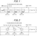
- the number of Mn-concentrated spots having a major axis length of more than 1.5 mm per 100 mm in length in the plate width direction is measured as follows. First, a sample for analysis is cut out from a steel plate and polished for preparation. This setup is carried out such that the surface of the sample becomes a cross-section perpendicular to the plate length direction of the steel plate (a C cross-section). Then, as illustrated in FIG.
- Mn concentration mapping is performed using an electron probe microanalyzer (EPMA) for three regions centering on each of the three points at the plate thickness center (t/2 position; t is the plate thickness) of the steel plate and ranging ⁇ 5 mm in the plate thickness direction (i.e., 10 mm thick) and ⁇ 200 mm in the plate width direction (i.e., 400 mm wide), at a W/4 position, a W/2 position, and a 3W/4 position from one end in the plate width direction of the steel plate, where W denotes the plate width (hereinafter, simply referred to as "W/4 position", "W/2 position", and "3W/4 position", respectively).
- EPMA electron probe microanalyzer
- the three regions may be one overlapping area depending on the plate width of the steel plate.
- the mapping is performed using an electronic probe with a accelerating voltage of 25 kV and a diameter of 0.15 mm.
- the number of Mn-concentrated spots having a major axis length of more than 1.5 mm is counted and converted to the number per 100 mm in length in the plate width direction.
- the steel microstructure of the high strength steel plate for sour-resistant line pipes disclosed herein is bainite microstructure in order to have a tensile strength as high as 520 MPa or more.
- the bainite microstructure includes a microstructure called bainitic ferrite or granular ferrite which contributes to transformation strengthening. These microstructures appear through transformation during or after accelerated cooling. If different microstructures such as ferrite, martensite, pearlite, martensite austenite constituent, retained austenite, and the like are mixed in the bainite microstructure, a decrease in strength, a deterioration in toughness, a rise in surface hardness, and the like occur.
- microstructures other than the bainite phase have smaller proportions.
- the volume fraction of such microstructures other than the bainitic phase is sufficiently low, their effects are negligible, and up to a certain amount is acceptable.
- the total of the steel microstructures other than bainite such as ferrite, martensite, pearlite, martensite austenite constituent, and retained austenite
- the HIC resistance at a W/4 position, a W/2 position, and a 3W/4 position is 10 % or less in terms of CAR, and that the variation in the HIC resistance in the plate width direction in terms of 3 ⁇ is 5% or less when ⁇ denotes a standard deviation of CARs.
- the HIC resistance at a W/4 position, a W/2 position, and a 3W/4 position is preferably 5 % or less in terms of CAR.
- the "HIC resistance at a W/4 position, a W/2 position, and a 3W/4 position" is evaluated as follows. As illustrated in FIG. 2 , in a C-section of the steel plate, centering on the plate thickness center at a W/4 position, a W/2 position, and a 3W/4 position (total of three points) in the plate width direction, test pieces of 20 mm thick and 20 mm wide are collected. From each of the three test pieces thus obtained, three samples are collected, and a total of nine samples are subjected to hydrogen-induced cracking (HIC) resistance examination. This examination is conducted in the Method A environment according to NACE TM0284, and the crack area ratio (CAR) is determined as a hydrogen-induced cracking criterion. In the high strength steel plate for sour-resistant line pipes disclosed herein, all nine CARs thus obtained are 10 % or less, and preferably 5 % or less.
- the "variation in the HIC resistance in the plate width direction" is evaluated in terms of 3 ⁇ when the standard deviation of nine CARs described above is calculated as ⁇ .
- the high strength steel plate disclosed herein is a steel plate for steel pipes having a strength of X60 grade or higher in API 5L, and thus has a tensile strength of 520 MPa or more.
- the manufacturing method disclosed herein comprises: subjecting steel having the above chemical composition to continuous casting to prepare a cast steel (slab); heating the slab; then hot rolling the slab to obtain a steel plate; and then subjecting the steel plate to controlled cooling. At this time, by performing secondary cooling in the continuous casting under particular conditions, and by performing the slab heating and controlled cooling under particular conditions, it is possible to manufacture a high strength steel plate for sour-resistant line pipes that has excellent HIC resistance in which variation in the HIC resistance in the plate width direction is suppressed.
- Coolant is sprayed on a cast steel 20 in a mist form from a plurality of two-fluid spray nozzles 10A and 10B to cool the cast steel 20 while feeding the cast steel 20 in its longitudinal direction.
- the plurality of two-fluid spray nozzles 10A and 10B are arranged at predetermined intervals in the width direction of the cast steel 20.
- the positions on the cast steel at which a water flux density is 50 % of the water flux density immediately below the two-fluid spray nozzles 10 are located away by a distance S (mm) from both ends of each spraying range of the coolant in the width direction of the cast steel 20.
- the overlapping margin between the spraying ranges of the coolant sprayed from the two-fluid spray nozzles 10A and 10B adjacent to each other is set in a range of 1.6 S to 2.4 S.
- FIGS. 3A and 3B schematically illustrate the injection ranges and the water flux density distributions of the coolant injected from two-fluid spray nozzle(s).
- FIG. 3A illustrates a distance S from both ends of the injection range at which a ratio of a water flux density at that position to a water flux density immediately below the two-fluid spray nozzle 10 is 50 %
- FIG. 3B illustrates the overlapping margin between the injection ranges of the coolant injected from the two two-fluid spray nozzles 10A and 10B.
- the distance S from both ends of the injection range of the coolant injected from the two-fluid spray nozzle 10 can be obtained as follows. First, a water flux density distribution in the width direction of the cast steel of the coolant injected from the two-fluid spray nozzle 10 is measured. The water flux density distribution can be measured by placing the two-fluid spray nozzle 10 above a group of measures finely divided in the width direction of the cast steel 1 and weighing the coolant injected from the two-fluid spray nozzle 10 for each measuring apparatus.
- the reason for setting the overlapping margin in a range of 1.6 S to 2.4 S is as follows. That is, in the case of the cast steel being subjected to secondary cooling with a plurality of two-fluid spray nozzles, even if the two-fluid spray nozzles are arranged such that the water flux density of the coolant injected from each two-fluid spray nozzle is uniform in the width direction of the cast steel, the collision pressure is low at both ends of each injection range of the coolant, resulting in low ability of cooling cast steel. Thus, it is impossible to cool the cast steel uniformly in the width direction.
- the overlapping margin is adjusted in the range of 1.6 S to 2.4 S, it is possible to uniformly cool the cast steel in the width direction, considering the collision pressure distribution in addition to the water flux density distribution in the width direction of the cast steel. That is, according to this method, it is possible to cool the cast steel without lowering the cooling ability in a region over which the injection ranges of the coolant from the adjacent two-fluid spray nozzles 10A and 10B overlap, and to suppress the surface temperature deviation in the width direction of the cast steel, enabling substantially uniform cooling. Accordingly, it is possible to prepare a slab with suppressed variation in the central segregation in the width direction.
- FIG. 3B illustrates an example using two two-fluid spray nozzles 10A and 10B
- the overlapping margin of the injection ranges of the coolant may be set as described above for those adjacent to each other among three or more two-fluid spray nozzles.
- the two-fluid spray nozzle include, but is not limited to, for example, a mist nozzle provided with a feed pipe for coolant and air, a mixing pipe, and a nozzle tip.
- the slab heating temperature is set to 1000 °C to 1300 °C. This temperature is the temperature in the heating furnace, and the slab is heated to this temperature to the center.
- the rolling finish temperature in terms of a temperature of the surface of the steel plate needs to be set in consideration of the required toughness for base metal and rolling efficiency. From the viewpoint of improving the strength and the HIC resistance, it is preferable to set the rolling finish temperature at or above the Ar 3 transformation temperature in terms of a temperature of the surface of the steel plate.
- the Ar 3 transformation temperature means the ferrite transformation start temperature during cooling, and can be determined, for example, from the components of steel according to the following equation.
- the rolling reduction ratio in a temperature range of 950 °C or lower, which corresponds to the austenite non-recrystallization temperature range, to 60 % or more.
- the temperature of the surface of the steel plate can be measured by a radiation thermometer or the like.
- Ar 3 (°C) 910 - 310[%C] - 80[%Mn] - 20[%Cu] - 15[%Cr] - 55[%Ni] - 80[%Mo], where [%X] indicates the content by mass% of the element X in steel.
- Cooling start temperature (Ar 3 - 10°C) or higher in terms of a temperature of the surface of the steel plate
- the temperature of the surface of the steel plate at the start of cooling is set to (Ar 3 - 10 °C) or higher.
- the cooling rate in terms of an average temperature of the steel plate is set to 15 °C/s or higher.
- the steel plate average cooling rate is preferably 20 °C/s or higher.
- the upper limit of the average cooling rate is not particularly limited, yet is preferably 80 °C/s or lower such that excessive low-temperature transformation products will not be generated.
- Cooling stop temperature 250 °C to 550 °C in terms of an average temperature of the steel plate
- a bainite phase is generated by performing controlled cooling to quench the steel plate to a temperature range of 250 °C to 550 °C which is the temperature range of bainite transformation.
- the cooling stop temperature exceeds 550 °C, bainite transformation is incomplete and sufficient strength can not be obtained.
- the cooling stop temperature is lower than 250 °C, the hardness markedly increases in the surface layer.
- the cooling stop temperature is preferably 350 °C to 500 °C.
- a temperature distribution in a cross section in the plate thickness direction can be determined in real time, for example, by difference calculation using a process computer on the basis of the surface temperature at the start of cooling measured with a radiation thermometer and the target surface temperature at the end of cooling.
- the average value of temperatures in the plate thickness direction in the temperature distribution is referred to as the "average temperature of the steel plate" in this description.
- a high strength steel pipe for sour-resistant line pipes (such as a UOE steel pipe, an electric-resistance welded steel pipe, and a spiral steel pipe) that has excellent material homogeneity in the steel plate and that is suitable for transporting crude oil and natural gas can be manufactured.
- an UOE steel pipe is manufactured by milling and beveling the edges of a steel plate, forming the steel plate into a steel pipe shape by C press, U-ing press, and O-ing press, then seam welding the butting portions by inner surface welding and outer surface welding, and optionally subjecting it to an expansion process.
- Any welding method may be applied as long as sufficient joint strength and joint toughness are guaranteed, yet it is preferable to use submerged arc welding from the viewpoint of excellent weld quality and manufacturing efficiency.
- Step Sample IDs A to M Steels having the chemical compositions listed in Table 1 (Steel Sample IDs A to M) were prepared and subjected to continuous casting to obtain slabs with a slab width of 1600 mm. Secondary cooling was performed with the overlapping margin of the injection ranges of the coolant injected in a mist form from the three two-fluid spray nozzles arranged at predetermined intervals in the width direction being set as listed in Table 2. Note that a distance S from both ends of the injection range of the coolant in the width direction of the cast steel 20 to the position where the ratio of a water flux density at that position to a water flux density immediately below the two-fluid spray nozzles is 50 % was fixed to 70 mm.
- each slab thus obtained was heated to the temperature as listed in Table 2, and then hot rolled with the rolling finish temperature and the rolling reduction ratio as listed in the table, to thereby obtain a steel plate with the plate thickness as listed in the table. Then, each steel plate was subjected to controlled cooling using a water-cooling type controlled-cooling device under the conditions listed in Table 2.
- microstructure of each obtained steel plate was observed with an optical microscope and a scanning electron microscope.
- the microstructures at the plate thickness center (i.e., t/2 position) of the steel plate are listed in Table 3.
- the number of Mn-concentrated spots having a major axis length of more than 1.5 mm was counted per 100 mm in length in the plate width direction in the manner described above.
- the target range was 3 or less. The results are listed in Table 3.
- the high strength steel plates for sour-resistant line pipes according to the present disclosure have excellent HIC resistance in which variation in the HIC resistance in the plate width direction is suppressed. Therefore, steel pipes (such as electric-resistance welded steel pipes, spiral steel pipes, and UOE steel pipes) manufactured by cold-forming the disclosed steel plate can be suitably used for transportation of crude oil and natural gas that contain hydrogen sulfides where sour resistance is required.
- steel pipes such as electric-resistance welded steel pipes, spiral steel pipes, and UOE steel pipes
Landscapes
- Chemical & Material Sciences (AREA)
- Engineering & Computer Science (AREA)
- Materials Engineering (AREA)
- Mechanical Engineering (AREA)
- Metallurgy (AREA)
- Organic Chemistry (AREA)
- Physics & Mathematics (AREA)
- Thermal Sciences (AREA)
- Crystallography & Structural Chemistry (AREA)
- Heat Treatment Of Steel (AREA)
Claims (2)
- Hochfeste Stahlplatte für sauergasresistente Leitungsrohre, umfassend: eine chemische Zusammensetzung, enthaltend, in Masse-%, C: 0,02 % bis 0,08 %, Si: 0,01 % bis 0,50 %, Mn: 0,50 % bis 1,80 %, P: 0,001 % bis 0,015 %, S: 0,0002 % bis 0,0015 %, Al: 0,01 % bis 0,08 % und Ca: 0,0005 % bis 0,005 %, optional mindestens eine ausgewählt aus der Gruppe, bestehend aus Cu: 0,50 % oder weniger, Ni: 0,50 % oder weniger, Cr: 0,50 % oder weniger und Mo: 0,50 % oder weniger, Nb: 0,005 % bis 0,1 %, V: 0,005 % bis 0,1 % und Ti: 0,005 % bis 0,1 %, wobei der Rest Fe und unvermeidliche Verunreinigungen sind, wobeiin einem Querschnitt senkrecht zu einer Walzrichtung der Stahlplatte die Anzahl der Mn-konzentrierten Punkte, die sich einer elliptischen Form annähern, die eine Hauptachsenlänge von mehr als 1,5 mm aufweist, 3 oder weniger pro 100 mm Länge in Plattenbreitenrichtung beträgt, in drei Regionen, die sich in jedem der drei Punkte an dem Plattendickenmittelpunkt der Stahlplatte zentrieren und in einem Bereich von ± 5 mm in der Plattendickenrichtung und ± 200 mm in der Plattenbreitenrichtung an einer W/4-Position, einer W/2-Position und einer 3W/4-Position von einem Ende in der Plattenbreitenrichtung der Stahlplatte liegen, wo W die Plattenbreite bezeichnet und wo der Mn-konzentrierte Punkt definiert als eine Stelle ist, in der die Mn-Konzentration 1,60 % oder mehr beträgt, wenn der Mn-Gehalt in der Stahlplatte 1,50 % oder weniger beträgt, und als eine Stelle, in der die Mn-Konzentration mindestens 0,10 % höher als der Mn-Gehalt in der Stahlplatte ist, wenn der Mn-Gehalt in der Stahlplatte mehr als 1,50 % und 1,80 % oder weniger beträgt, wo in dem Querschnitt senkrecht zu der Walzrichtung der Stahlplatte, zentriert auf dem Plattendickenmittelpunkt an der W/4-Position, der W/2-Position und der 3W/4-Position (insgesamt drei Punkte) in Plattenbreitenrichtung, 20 mm dicke und 20 mm breite Probestücke gesammelt werden und von jedem der drei so erlangten Probestücke drei Proben genommen werden, und insgesamt neun Proben einer Prüfung von wasserstoffinduzierter Rissbildungs-Widerstand (hydrogen-induced cracking, HIC) unterzogen werden, der HIC-Widerstand aller neun Proben 10 % oder weniger in Bezug auf CAR beträgt und wo der CAR gemäß NACE TM0284 gemessen wird, die Variation des HIC-Widerstands in Plattenbreitenrichtung in Bezug auf 3σ 5 % oder weniger beträgt, wenn σ eine Standardabweichung der CAR der neun Proben bezeichnet, undeine Zugfestigkeit 520 MPa oder mehr beträgt, wobei die Zugfestigkeit gemäß API-5L gemessen wird.
- Hochfestes Stahlrohr unter Verwendung der hochfesten Stahlplatte für sauergasresistente Leitungsrohre nach Anspruch 1.
Applications Claiming Priority (1)
| Application Number | Priority Date | Filing Date | Title |
|---|---|---|---|
| PCT/JP2017/037891 WO2019077725A1 (ja) | 2017-10-19 | 2017-10-19 | 耐サワーラインパイプ用高強度鋼板およびこれを用いた高強度鋼管 |
Publications (3)
| Publication Number | Publication Date |
|---|---|
| EP3674433A1 EP3674433A1 (de) | 2020-07-01 |
| EP3674433A4 EP3674433A4 (de) | 2020-07-29 |
| EP3674433B1 true EP3674433B1 (de) | 2025-01-29 |
Family
ID=66174107
Family Applications (1)
| Application Number | Title | Priority Date | Filing Date |
|---|---|---|---|
| EP17929314.7A Active EP3674433B1 (de) | 2017-10-19 | 2017-10-19 | Hochfestes stahlblech für sauergasresistente leitungsrohre und hochfestes stahlrohr damit |
Country Status (6)
| Country | Link |
|---|---|
| EP (1) | EP3674433B1 (de) |
| JP (1) | JP6798565B2 (de) |
| KR (1) | KR102497363B1 (de) |
| CN (1) | CN111247261A (de) |
| BR (1) | BR112020007057B1 (de) |
| WO (1) | WO2019077725A1 (de) |
Families Citing this family (2)
| Publication number | Priority date | Publication date | Assignee | Title |
|---|---|---|---|---|
| CN113151737B (zh) * | 2021-02-25 | 2022-06-07 | 江阴兴澄特种钢铁有限公司 | 一种抗氢致裂纹的08Ni3DR钢板及其制造方法 |
| JP7670004B2 (ja) * | 2022-08-04 | 2025-04-30 | Jfeスチール株式会社 | 40キロ級非調質型厚鋼板、溶接鋼管およびそれらの製造方法 |
Family Cites Families (22)
| Publication number | Priority date | Publication date | Assignee | Title |
|---|---|---|---|---|
| JP2647302B2 (ja) | 1992-03-30 | 1997-08-27 | 新日本製鐵株式会社 | 耐水素誘起割れ性の優れた高強度鋼板の製造方法 |
| JPH07136752A (ja) * | 1993-11-18 | 1995-05-30 | Nippon Steel Corp | 連続鋳造における鋳片の2次冷却方法およびその装置 |
| JPH07173536A (ja) | 1993-12-16 | 1995-07-11 | Nippon Steel Corp | 耐サワー性の優れた高強度ラインパイプ用鋼板の製造法 |
| JPH0957327A (ja) | 1995-08-22 | 1997-03-04 | Sumitomo Metal Ind Ltd | 厚鋼板のスケール除去方法 |
| JP3796133B2 (ja) | 2000-04-18 | 2006-07-12 | 新日本製鐵株式会社 | 厚鋼板冷却方法およびその装置 |
| JP2002327212A (ja) | 2001-02-28 | 2002-11-15 | Nkk Corp | 耐サワーラインパイプ用鋼板の製造方法 |
| JP3711896B2 (ja) | 2001-06-26 | 2005-11-02 | Jfeスチール株式会社 | 高強度ラインパイプ用鋼板の製造方法 |
| JP2003313638A (ja) * | 2002-04-22 | 2003-11-06 | Jfe Steel Kk | 耐hic特性に優れた高強度鋼板及びその製造方法 |
| JP5634662B2 (ja) * | 2008-02-07 | 2014-12-03 | Jfeスチール株式会社 | 均質性に優れた加速冷却型薄肉厚鋼板 |
| BR112012005189A2 (pt) * | 2009-09-09 | 2016-03-08 | Nippon Steel Corp | chapas de aço para uso em tubos para oleodutos de alta resistência e aço para uso em tubos para oleodutos de alta resistência com excelente tenacidade a baixa temperatura |
| KR101224955B1 (ko) * | 2010-08-30 | 2013-01-22 | 현대제철 주식회사 | 스트랜드 냉각 제어장치 및 그 방법 |
| JP5672916B2 (ja) * | 2010-09-30 | 2015-02-18 | Jfeスチール株式会社 | 耐サワーラインパイプ用高強度鋼板およびその製造方法並びに耐サワーラインパイプ用高強度鋼板を用いた高強度鋼管 |
| JP5192074B2 (ja) * | 2010-12-20 | 2013-05-08 | Thk株式会社 | シール部材及びこれを用いた直線運動案内装置 |
| JP5900303B2 (ja) * | 2011-12-09 | 2016-04-06 | Jfeスチール株式会社 | 鋼板内の材質均一性に優れた耐サワーラインパイプ用高強度鋼板とその製造方法 |
| JP6044247B2 (ja) * | 2011-12-13 | 2016-12-14 | Jfeスチール株式会社 | 鋼材の耐水素割れ感受性を評価する方法及び耐水素割れ感受性が良好な高強度耐サワーラインパイプ用鋼板 |
| JP5853661B2 (ja) * | 2011-12-15 | 2016-02-09 | Jfeスチール株式会社 | 高強度耐サワーラインパイプ用鋼板、その素材及び高強度耐サワーラインパイプ用鋼板の製造方法 |
| JP2014077642A (ja) * | 2012-10-09 | 2014-05-01 | Jfe Steel Corp | 鋼材のhic感受性の評価方法およびそれを用いた耐hic性に優れたラインパイプ用高強度厚鋼板の製造方法 |
| JP6169025B2 (ja) * | 2013-03-29 | 2017-07-26 | 株式会社神戸製鋼所 | 耐水素誘起割れ性と靭性に優れた鋼板およびラインパイプ用鋼管 |
| EP3015562B1 (de) * | 2013-06-27 | 2018-08-01 | JFE Steel Corporation | Heissgewalztes hochfestes stahlblech und verfahren zur herstellung davon |
| JP6115735B2 (ja) * | 2014-07-25 | 2017-04-19 | Jfeスチール株式会社 | 鋼の連続鋳造方法 |
| KR20160147153A (ko) * | 2015-06-12 | 2016-12-22 | 동국제강주식회사 | 라인파이프용 고강도 후강판 제조 방법 및 이에 의해 제조된 라인파인프용 고강도 후강판 |
| JP6641875B2 (ja) * | 2015-10-21 | 2020-02-05 | 日本製鉄株式会社 | 低降伏比鋼板およびその製造方法 |
-
2017
- 2017-10-19 JP JP2018564993A patent/JP6798565B2/ja active Active
- 2017-10-19 BR BR112020007057-2A patent/BR112020007057B1/pt active IP Right Grant
- 2017-10-19 CN CN201780095998.XA patent/CN111247261A/zh active Pending
- 2017-10-19 WO PCT/JP2017/037891 patent/WO2019077725A1/ja not_active Ceased
- 2017-10-19 EP EP17929314.7A patent/EP3674433B1/de active Active
- 2017-10-19 KR KR1020207011797A patent/KR102497363B1/ko active Active
Also Published As
| Publication number | Publication date |
|---|---|
| EP3674433A4 (de) | 2020-07-29 |
| CN111247261A (zh) | 2020-06-05 |
| BR112020007057A2 (pt) | 2020-10-06 |
| JP6798565B2 (ja) | 2020-12-09 |
| EP3674433A1 (de) | 2020-07-01 |
| BR112020007057B1 (pt) | 2022-07-12 |
| KR102497363B1 (ko) | 2023-02-08 |
| KR20200058490A (ko) | 2020-05-27 |
| JPWO2019077725A1 (ja) | 2019-11-14 |
| WO2019077725A1 (ja) | 2019-04-25 |
Similar Documents
| Publication | Publication Date | Title |
|---|---|---|
| JP6521197B2 (ja) | 耐サワーラインパイプ用高強度鋼板およびその製造方法並びに耐サワーラインパイプ用高強度鋼板を用いた高強度鋼管 | |
| EP3192890B1 (de) | Hochfestes nahtloses stahlrohr zur verwendung in ölbohrlöchern und herstellungsverfahren dafür | |
| CN103958715B (zh) | 止裂性优异的高强度厚钢板 | |
| US10023946B2 (en) | Thick steel sheet having excellent CTOD properties in multilayer welded joints, and manufacturing method for thick steel sheet | |
| JP5141073B2 (ja) | X70グレード以下の低降伏比高強度高靱性鋼管およびその製造方法 | |
| EP3276024B1 (de) | Dicke stahlplatte für strukturrohr, verfahren zur herstellung der dicken stahlplatte für strukturrohr sowie strukturrohr | |
| EP3192889B1 (de) | Hochfestes nahtloses stahlrohr zur verwendung in ölbohrlöchern und herstellungsverfahren dafür | |
| EP3859026A1 (de) | Hochfestes stahlblech für sauergasbeständiges leitungsrohr, verfahren zur herstellung davon und hochfestes stahlrohr mit verwendung von hochfestem stahlblech für sauergasbeständiges leitungsrohr | |
| EP3633057B1 (de) | Stahlplatte und herstellungsverfahren | |
| EP4095280A1 (de) | Elektrogeschweisstes stahlrohr und verfahren zu seiner herstellung | |
| JP2015190026A (ja) | ラインパイプ用厚肉高強度電縫鋼管およびその製造方法 | |
| EP3276025A1 (de) | Stahlplatte für ein strukturrohr, verfahren zur herstellung einer stahlplatte für ein strukturrohr und strukturrohr | |
| KR20210050548A (ko) | 내사워 라인 파이프용 고강도 강판 및 그 제조 방법 그리고 내사워 라인 파이프용 고강도 강판을 사용한 고강도 강관 | |
| KR20230170038A (ko) | 고강도 열연 강판 및 그의 제조 방법, 그리고 고강도 전봉 강관 및 그의 제조 방법 | |
| JP4507708B2 (ja) | 低降伏比高強度高靱性鋼板の製造方法 | |
| JP7264269B2 (ja) | 耐サワーラインパイプ用高強度鋼板およびその製造方法並びに耐サワーラインパイプ用高強度鋼板を用いた高強度鋼管 | |
| EP3674433B1 (de) | Hochfestes stahlblech für sauergasresistente leitungsrohre und hochfestes stahlrohr damit | |
| JP6521196B1 (ja) | 耐サワーラインパイプ用高強度鋼板およびその製造方法並びに耐サワーラインパイプ用高強度鋼板を用いた高強度鋼管 | |
| JP5842577B2 (ja) | 耐歪時効性に優れた高靱性低降伏比高強度鋼板 | |
| JP6536459B2 (ja) | 厚鋼板およびその製造方法 | |
| JP4899885B2 (ja) | 靭性および脆性亀裂伝播停止特性に優れた薄肉調質高張力鋼板およびその製造方法 | |
| EP4675003A1 (de) | Stahlrohr und verfahren zur herstellung davon | |
| EP4502220A1 (de) | Hochfestes stahlblech für sauerbeständiges leitungsrohr und verfahren zur herstellung davon sowie hochfestes stahlrohr mit hochfestem stahlblech für sauerbeständiges leitungsrohr | |
| EP4578981A1 (de) | Hochfestes leitungsrohrstahlmaterial mit hervorragender bruchzähigkeit in wasserstoff, stahlrohr für hochfeste leitungsrohre und verfahren zur herstellung davon | |
| EP4060070A1 (de) | Hochfestes nahtloses stahlrohr und verfahren zur herstellung desselben |
Legal Events
| Date | Code | Title | Description |
|---|---|---|---|
| STAA | Information on the status of an ep patent application or granted ep patent |
Free format text: STATUS: THE INTERNATIONAL PUBLICATION HAS BEEN MADE |
|
| PUAI | Public reference made under article 153(3) epc to a published international application that has entered the european phase |
Free format text: ORIGINAL CODE: 0009012 |
|
| STAA | Information on the status of an ep patent application or granted ep patent |
Free format text: STATUS: REQUEST FOR EXAMINATION WAS MADE |
|
| 17P | Request for examination filed |
Effective date: 20200327 |
|
| AK | Designated contracting states |
Kind code of ref document: A1 Designated state(s): AL AT BE BG CH CY CZ DE DK EE ES FI FR GB GR HR HU IE IS IT LI LT LU LV MC MK MT NL NO PL PT RO RS SE SI SK SM TR |
|
| AX | Request for extension of the european patent |
Extension state: BA ME |
|
| A4 | Supplementary search report drawn up and despatched |
Effective date: 20200629 |
|
| RIC1 | Information provided on ipc code assigned before grant |
Ipc: C22C 38/04 20060101ALI20200623BHEP Ipc: C21D 9/46 20060101ALI20200623BHEP Ipc: C22C 38/08 20060101ALI20200623BHEP Ipc: C22C 38/12 20060101ALI20200623BHEP Ipc: C22C 38/14 20060101ALI20200623BHEP Ipc: C22C 38/58 20060101ALI20200623BHEP Ipc: C22C 38/06 20060101ALI20200623BHEP Ipc: C21D 8/02 20060101ALI20200623BHEP Ipc: C22C 38/16 20060101ALI20200623BHEP Ipc: C22C 38/18 20060101ALI20200623BHEP Ipc: C22C 38/02 20060101ALI20200623BHEP Ipc: C22C 38/00 20060101AFI20200623BHEP |
|
| DAV | Request for validation of the european patent (deleted) | ||
| DAX | Request for extension of the european patent (deleted) | ||
| GRAP | Despatch of communication of intention to grant a patent |
Free format text: ORIGINAL CODE: EPIDOSNIGR1 |
|
| STAA | Information on the status of an ep patent application or granted ep patent |
Free format text: STATUS: GRANT OF PATENT IS INTENDED |
|
| INTG | Intention to grant announced |
Effective date: 20241018 |
|
| GRAS | Grant fee paid |
Free format text: ORIGINAL CODE: EPIDOSNIGR3 |
|
| GRAA | (expected) grant |
Free format text: ORIGINAL CODE: 0009210 |
|
| STAA | Information on the status of an ep patent application or granted ep patent |
Free format text: STATUS: THE PATENT HAS BEEN GRANTED |
|
| AK | Designated contracting states |
Kind code of ref document: B1 Designated state(s): AL AT BE BG CH CY CZ DE DK EE ES FI FR GB GR HR HU IE IS IT LI LT LU LV MC MK MT NL NO PL PT RO RS SE SI SK SM TR |
|
| REG | Reference to a national code |
Ref country code: GB Ref legal event code: FG4D |
|
| REG | Reference to a national code |
Ref country code: CH Ref legal event code: EP |
|
| REG | Reference to a national code |
Ref country code: DE Ref legal event code: R096 Ref document number: 602017087605 Country of ref document: DE |
|
| REG | Reference to a national code |
Ref country code: IE Ref legal event code: FG4D |
|
| REG | Reference to a national code |
Ref country code: NL Ref legal event code: MP Effective date: 20250129 |
|
| PG25 | Lapsed in a contracting state [announced via postgrant information from national office to epo] |
Ref country code: NL Free format text: LAPSE BECAUSE OF FAILURE TO SUBMIT A TRANSLATION OF THE DESCRIPTION OR TO PAY THE FEE WITHIN THE PRESCRIBED TIME-LIMIT Effective date: 20250129 |
|
| PG25 | Lapsed in a contracting state [announced via postgrant information from national office to epo] |
Ref country code: RS Free format text: LAPSE BECAUSE OF FAILURE TO SUBMIT A TRANSLATION OF THE DESCRIPTION OR TO PAY THE FEE WITHIN THE PRESCRIBED TIME-LIMIT Effective date: 20250429 |
|
| PG25 | Lapsed in a contracting state [announced via postgrant information from national office to epo] |
Ref country code: FI Free format text: LAPSE BECAUSE OF FAILURE TO SUBMIT A TRANSLATION OF THE DESCRIPTION OR TO PAY THE FEE WITHIN THE PRESCRIBED TIME-LIMIT Effective date: 20250129 |
|
| PG25 | Lapsed in a contracting state [announced via postgrant information from national office to epo] |
Ref country code: PL Free format text: LAPSE BECAUSE OF FAILURE TO SUBMIT A TRANSLATION OF THE DESCRIPTION OR TO PAY THE FEE WITHIN THE PRESCRIBED TIME-LIMIT Effective date: 20250129 |
|
| PG25 | Lapsed in a contracting state [announced via postgrant information from national office to epo] |
Ref country code: ES Free format text: LAPSE BECAUSE OF FAILURE TO SUBMIT A TRANSLATION OF THE DESCRIPTION OR TO PAY THE FEE WITHIN THE PRESCRIBED TIME-LIMIT Effective date: 20250129 |
|
| REG | Reference to a national code |
Ref country code: LT Ref legal event code: MG9D |
|
| PG25 | Lapsed in a contracting state [announced via postgrant information from national office to epo] |
Ref country code: NO Free format text: LAPSE BECAUSE OF FAILURE TO SUBMIT A TRANSLATION OF THE DESCRIPTION OR TO PAY THE FEE WITHIN THE PRESCRIBED TIME-LIMIT Effective date: 20250429 Ref country code: IS Free format text: LAPSE BECAUSE OF FAILURE TO SUBMIT A TRANSLATION OF THE DESCRIPTION OR TO PAY THE FEE WITHIN THE PRESCRIBED TIME-LIMIT Effective date: 20250529 |
|
| PG25 | Lapsed in a contracting state [announced via postgrant information from national office to epo] |
Ref country code: HR Free format text: LAPSE BECAUSE OF FAILURE TO SUBMIT A TRANSLATION OF THE DESCRIPTION OR TO PAY THE FEE WITHIN THE PRESCRIBED TIME-LIMIT Effective date: 20250129 |
|
| PG25 | Lapsed in a contracting state [announced via postgrant information from national office to epo] |
Ref country code: LV Free format text: LAPSE BECAUSE OF FAILURE TO SUBMIT A TRANSLATION OF THE DESCRIPTION OR TO PAY THE FEE WITHIN THE PRESCRIBED TIME-LIMIT Effective date: 20250129 Ref country code: PT Free format text: LAPSE BECAUSE OF FAILURE TO SUBMIT A TRANSLATION OF THE DESCRIPTION OR TO PAY THE FEE WITHIN THE PRESCRIBED TIME-LIMIT Effective date: 20250529 |
|
| PG25 | Lapsed in a contracting state [announced via postgrant information from national office to epo] |
Ref country code: GR Free format text: LAPSE BECAUSE OF FAILURE TO SUBMIT A TRANSLATION OF THE DESCRIPTION OR TO PAY THE FEE WITHIN THE PRESCRIBED TIME-LIMIT Effective date: 20250430 Ref country code: BG Free format text: LAPSE BECAUSE OF FAILURE TO SUBMIT A TRANSLATION OF THE DESCRIPTION OR TO PAY THE FEE WITHIN THE PRESCRIBED TIME-LIMIT Effective date: 20250129 |
|
| PG25 | Lapsed in a contracting state [announced via postgrant information from national office to epo] |
Ref country code: SE Free format text: LAPSE BECAUSE OF FAILURE TO SUBMIT A TRANSLATION OF THE DESCRIPTION OR TO PAY THE FEE WITHIN THE PRESCRIBED TIME-LIMIT Effective date: 20250129 |
|
| PG25 | Lapsed in a contracting state [announced via postgrant information from national office to epo] |
Ref country code: SM Free format text: LAPSE BECAUSE OF FAILURE TO SUBMIT A TRANSLATION OF THE DESCRIPTION OR TO PAY THE FEE WITHIN THE PRESCRIBED TIME-LIMIT Effective date: 20250129 |
|
| PG25 | Lapsed in a contracting state [announced via postgrant information from national office to epo] |
Ref country code: DK Free format text: LAPSE BECAUSE OF FAILURE TO SUBMIT A TRANSLATION OF THE DESCRIPTION OR TO PAY THE FEE WITHIN THE PRESCRIBED TIME-LIMIT Effective date: 20250129 |
|
| PG25 | Lapsed in a contracting state [announced via postgrant information from national office to epo] |
Ref country code: IT Free format text: LAPSE BECAUSE OF FAILURE TO SUBMIT A TRANSLATION OF THE DESCRIPTION OR TO PAY THE FEE WITHIN THE PRESCRIBED TIME-LIMIT Effective date: 20250129 |
|
| PGFP | Annual fee paid to national office [announced via postgrant information from national office to epo] |
Ref country code: FR Payment date: 20250908 Year of fee payment: 9 |
|
| PG25 | Lapsed in a contracting state [announced via postgrant information from national office to epo] |
Ref country code: EE Free format text: LAPSE BECAUSE OF FAILURE TO SUBMIT A TRANSLATION OF THE DESCRIPTION OR TO PAY THE FEE WITHIN THE PRESCRIBED TIME-LIMIT Effective date: 20250129 Ref country code: CZ Free format text: LAPSE BECAUSE OF FAILURE TO SUBMIT A TRANSLATION OF THE DESCRIPTION OR TO PAY THE FEE WITHIN THE PRESCRIBED TIME-LIMIT Effective date: 20250129 |
|
| PG25 | Lapsed in a contracting state [announced via postgrant information from national office to epo] |
Ref country code: RO Free format text: LAPSE BECAUSE OF FAILURE TO SUBMIT A TRANSLATION OF THE DESCRIPTION OR TO PAY THE FEE WITHIN THE PRESCRIBED TIME-LIMIT Effective date: 20250129 |
|
| PG25 | Lapsed in a contracting state [announced via postgrant information from national office to epo] |
Ref country code: SK Free format text: LAPSE BECAUSE OF FAILURE TO SUBMIT A TRANSLATION OF THE DESCRIPTION OR TO PAY THE FEE WITHIN THE PRESCRIBED TIME-LIMIT Effective date: 20250129 |
|
| REG | Reference to a national code |
Ref country code: DE Ref legal event code: R097 Ref document number: 602017087605 Country of ref document: DE |
|
| PLBE | No opposition filed within time limit |
Free format text: ORIGINAL CODE: 0009261 |
|
| STAA | Information on the status of an ep patent application or granted ep patent |
Free format text: STATUS: NO OPPOSITION FILED WITHIN TIME LIMIT |
|
| 26N | No opposition filed |
Effective date: 20251030 |
|
| PGFP | Annual fee paid to national office [announced via postgrant information from national office to epo] |
Ref country code: DE Payment date: 20250902 Year of fee payment: 9 |
|
| PGFP | Annual fee paid to national office [announced via postgrant information from national office to epo] |
Ref country code: AT Payment date: 20250925 Year of fee payment: 9 |