EP3674472A1 - Piège pour boutons et tamis pour appareil de blanchisserie - Google Patents
Piège pour boutons et tamis pour appareil de blanchisserie Download PDFInfo
- Publication number
- EP3674472A1 EP3674472A1 EP19203709.1A EP19203709A EP3674472A1 EP 3674472 A1 EP3674472 A1 EP 3674472A1 EP 19203709 A EP19203709 A EP 19203709A EP 3674472 A1 EP3674472 A1 EP 3674472A1
- Authority
- EP
- European Patent Office
- Prior art keywords
- trap
- fluid
- fingers
- laundry appliance
- elongated body
- Prior art date
- Legal status (The legal status is an assumption and is not a legal conclusion. Google has not performed a legal analysis and makes no representation as to the accuracy of the status listed.)
- Granted
Links
Images



Classifications
-
- D—TEXTILES; PAPER
- D06—TREATMENT OF TEXTILES OR THE LIKE; LAUNDERING; FLEXIBLE MATERIALS NOT OTHERWISE PROVIDED FOR
- D06F—LAUNDERING, DRYING, IRONING, PRESSING OR FOLDING TEXTILE ARTICLES
- D06F39/00—Details of washing machines not specific to a single type of machines covered by groups D06F9/00 - D06F27/00
- D06F39/10—Filtering arrangements
-
- D—TEXTILES; PAPER
- D06—TREATMENT OF TEXTILES OR THE LIKE; LAUNDERING; FLEXIBLE MATERIALS NOT OTHERWISE PROVIDED FOR
- D06F—LAUNDERING, DRYING, IRONING, PRESSING OR FOLDING TEXTILE ARTICLES
- D06F21/00—Washing machines with receptacles, e.g. perforated, having a rotary movement, e.g. oscillatory movement
- D06F21/02—Washing machines with receptacles, e.g. perforated, having a rotary movement, e.g. oscillatory movement about a horizontal axis
-
- D—TEXTILES; PAPER
- D06—TREATMENT OF TEXTILES OR THE LIKE; LAUNDERING; FLEXIBLE MATERIALS NOT OTHERWISE PROVIDED FOR
- D06F—LAUNDERING, DRYING, IRONING, PRESSING OR FOLDING TEXTILE ARTICLES
- D06F39/00—Details of washing machines not specific to a single type of machines covered by groups D06F9/00 - D06F27/00
- D06F39/08—Liquid supply or discharge arrangements
- D06F39/083—Liquid discharge or recirculation arrangements
-
- D—TEXTILES; PAPER
- D06—TREATMENT OF TEXTILES OR THE LIKE; LAUNDERING; FLEXIBLE MATERIALS NOT OTHERWISE PROVIDED FOR
- D06F—LAUNDERING, DRYING, IRONING, PRESSING OR FOLDING TEXTILE ARTICLES
- D06F2103/00—Parameters monitored or detected for the control of domestic laundry washing machines, washer-dryers or laundry dryers
- D06F2103/42—Parameters monitored or detected for the control of domestic laundry washing machines, washer-dryers or laundry dryers related to filters or pumps
-
- D—TEXTILES; PAPER
- D06—TREATMENT OF TEXTILES OR THE LIKE; LAUNDERING; FLEXIBLE MATERIALS NOT OTHERWISE PROVIDED FOR
- D06F—LAUNDERING, DRYING, IRONING, PRESSING OR FOLDING TEXTILE ARTICLES
- D06F2105/00—Systems or parameters controlled or affected by the control systems of washing machines, washer-dryers or laundry dryers
- D06F2105/34—Filtering, e.g. control of lint removal devices
-
- D—TEXTILES; PAPER
- D06—TREATMENT OF TEXTILES OR THE LIKE; LAUNDERING; FLEXIBLE MATERIALS NOT OTHERWISE PROVIDED FOR
- D06F—LAUNDERING, DRYING, IRONING, PRESSING OR FOLDING TEXTILE ARTICLES
- D06F39/00—Details of washing machines not specific to a single type of machines covered by groups D06F9/00 - D06F27/00
- D06F39/08—Liquid supply or discharge arrangements
- D06F39/083—Liquid discharge or recirculation arrangements
- D06F39/085—Arrangements or adaptations of pumps
-
- D—TEXTILES; PAPER
- D06—TREATMENT OF TEXTILES OR THE LIKE; LAUNDERING; FLEXIBLE MATERIALS NOT OTHERWISE PROVIDED FOR
- D06F—LAUNDERING, DRYING, IRONING, PRESSING OR FOLDING TEXTILE ARTICLES
- D06F43/00—Dry-cleaning apparatus or methods using volatile solvents
- D06F43/08—Associated apparatus for handling and recovering the solvents
- D06F43/081—Reclaiming or recovering the solvent from a mixture of solvent and contaminants, e.g. by distilling
- D06F43/085—Filtering arrangements; Filter cleaning; Filter-aid powder dispensers
Definitions
- the device is in the field of laundry appliances, and more specifically, a laundry appliance having a button trap and sieve that capture foreign objects and also allows for the passage of fine particulate material and lint particles therethrough.
- a laundry appliance includes a wash tub disposed within a cabinet.
- a rotating drum is disposed within the wash tub.
- a drain system directs a fluid from the wash tub to a fluid pump.
- a trap is disposed within a tub drain of the wash tub.
- the trap includes an elongated body having a plurality of fingers that extend across an aperture defined within the elongated body. The plurality of fingers are configured to permit passage of particulate material and prevent passage of foreign objects through the elongated body.
- a laundry appliance includes a wash tub disposed within a cabinet and having a rotating drum positioned therein.
- a drain system directs a fluid from the wash tub to a fluid pump.
- a tub drain directs fluid from the wash tub to a fluid pump system.
- a foreign-object trap is disposed within the tub drain.
- the foreign-object trap includes an elongated body and a plurality of fingers that extend in a direction of a flow of fluid through the foreign-object trap. The plurality of fingers are configured to permit passage of particulate material toward the pump system and prevent passage of foreign objects through the elongated body.
- a laundry appliance includes a wash tub disposed within a cabinet and having a rotating drum positioned therein.
- a drain system directs a fluid from the wash tub to a fluid pump.
- a tub drain that directs fluid from the wash tub to a fluid pump system.
- a foreign-object trap is disposed within the tub drain.
- the foreign-object trap includes an elongated body and a plurality of apertures that permit passage of particulate material toward the pump system and prevent passage of foreign objects through the elongated body.
- the elongated body defines a flow restriction space that permits upward movement of air as fluid moves through the plurality of apertures and toward the fluid pump system.
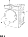
- the terms "upper,” “lower,” “right,” “left,” “rear,” “front,” “vertical,” “horizontal,” and derivatives thereof shall relate to the device as oriented in FIG. 1 .
- the device may assume various alternative orientations and step sequences, except where expressly specified to the contrary.
- the specific devices and processes illustrated in the attached drawings, and described in the following specification are simply exemplary embodiments of the inventive concepts defined in the appended claims. Hence, specific dimensions and other physical characteristics relating to the embodiments disclosed herein are not to be considered as limiting, unless the claims expressly state otherwise.
- reference numeral 10 generally refers to a button trap or foreign-object trap that can be incorporated within a trap housing 12 for an appliance 14.
- the button trap 10 is configured to capture and retain foreign objects 16 such as buttons, coins, caps, and other foreign objects 16 that are often left within clothing being laundered.
- the button trap 10 is configured to allow for the substantially free passage of fine particulate material 18, such as lint particles, therethrough.
- the laundry appliance 14 includes a wash tub 20 that is configured within a cabinet 22.
- a rotating drum 24 is disposed within the wash tub 20.
- a fluid pump system or drain system 26 is included within the appliance 14 and directs fluid 28 from the tub 20 and to at least one fluid pump 30.
- a trap typically in the form of a button trap 10, is disposed within a tub drain 32 of the wash tub 20.
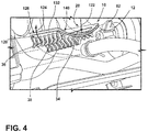
- the button trap 10 typically includes an elongated body 34 having a plurality of fingers 36 that extend across an aperture 38 defined within the elongated body 34.
- the laundry appliance 14 can typically be in the form of a horizontal axis laundry appliance 14.
- This laundry appliance 14 can include the tub 20 that is generally oriented in a horizontal configuration or a sloped configuration. It should be understood that other types of laundry appliances 14 can use the button trap 10 disclosed herein.
- the rotating drum 24 rotationally operates within the wash tub 20, where the rotating drum 24 operates to agitate laundry being processed therein.
- fluid 28 in the form of water and various laundry chemistries are disposed within the tub 20 and the rotating drum 24.
- the fluid 28 contained within the tub 20 and the rotating drum 24 is drained therefrom during various stages of a laundry cycle.
- This drained fluid 28 is directed through the tub drain 32.
- Foreign objects 16 that are entrapped within this fluid 28 being drained from the tub 20 can include items, similar to those described above.
- the button trap 10 contained therein is configured to prevent passage of these foreign objects 16.
- These foreign objects 16, being solid and typically larger in size, can cause damage to one or more pumps 30 that are located downstream of the trap housing 12 and the button trap 10.
- fine particulate material 18 captured within the fluid 28 leaving the drum 24 is allowed to pass through the trap housing 12 and the fingers 36 of the button trap 10.
- This particulate material 18 is configured to be conveniently processed by the one or more fluid pumps 30 during operation of the appliance 14.
- These pumps 30 are typically designed to process and allow passage of this particulate material 18.
- the button trap 10 includes the plurality of fingers 36 that typically extend across a centerline 50 of the aperture 38.
- the button trap 10 can include a plurality of apertures 38 that extend through the elongated body 34. The orientation of these various apertures 38 can be utilized for directing fluid 28 in a particular direction, such as toward a particular fluid pump 30 within the appliance 14.
- the fingers 36 can include opposing sets 52 of fingers 36 that each extend across the centerline 50 of the aperture 38. In this manner, the elongated fingers 36 can form a generally overlapping structure that can be used to prevent the passage of foreign objects 16.
- fine particulate material 18 captured within the fluid 28 leaving the drum 24 is allowed to pass through the trap housing 12 and the fingers 36 of the button trap 10.
- This particulate material 18 is configured to be conveniently processed by the one or more fluid pumps 30 during operation of the appliance 14.
- the plurality of fingers 36 are adapted to extend in a generally angular direction 60 that follows the flow 62 of fluid 28 therethrough.
- the flow 62 of fluid 28 through the fingers 36 typically engages an angled or arcuate surface 64 of each of the elongated fingers 36.
- These angled or arcuate surfaces 64 of the various fingers 36 allows lint to conveniently slide off of the fingers 36 and proceed downstream of the trap housing 12 and toward the various pumps 30 of the appliance 14.
- the various fingers 36 of the plurality of fingers 36 can define an arcuate shape that bends in the direction of the flow 62 of fluid 28 through the button trap 10.
- the elongated body 34 of the button trap 10 can include three separate apertures 38.
- each of these apertures 38 can include opposing sets 52 of fingers 36 that extend to the centerline 50 of each respective aperture 38. It is contemplated that the various sets of opposing fingers 36 can also extend beyond the centerline 50 to form intersecting sets of fingers 36.
- each of the opposing sets 52 of fingers 36 can extend toward the centerline 50, but may not reach the centerline 50 such that an elongated space within the aperture 38 may exist between the opposing sets 52 of fingers 36.
- the exact configuration of the elongated fingers 36 within the various apertures 38 of the button trap 10 can vary depending upon the configuration of a particular appliance 14 and the desired flow 62 of fluid 28 that is designed for the particular appliance 14 through the button trap 10.
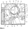
- the button trap 10 can include a base 70 that is disposed within a trap receptacle 72 of the trap housing 12. This base 70 can be rotationally or threadingly disposed within the trap receptacle 72. In various aspects of the device, the base 70 can include an orienting feature 74 that rotationally locates the elongated body 34 and the various apertures 38 within the trap housing 12. This locating feature defined within the base 70 of the button trap 10 can engage a portion of the trap receptacle 72 to properly align the button trap 10 within the trap housing 12.
- the base 70 of the button trap 10 defines an inner wall 80.
- the elongated body 34 is configured to extend from this inner wall 80 and through the trap housing 12.
- fluid 28 leaving the rotating drum 24 and the tub 20 is configured to enter the trap housing 12 through an inlet 82.
- This inlet 82 typically opposes the inner wall 80 of the base 70 for the button trap 10.
- the fluid 28 is directed through the button trap 10. More specifically, the fluid 28 typically enters into each of the apertures 38 and between the various fingers 36 that are defined within each aperture 38.
- the trap housing 12 can include a sediment zone 84 that is positioned below a water level within the trap housing 12.
- the sediment zone 84 is also positioned at least partially below the elongated body 34. Accordingly, the fine particulate material 18 is able to pass through the various apertures 38 and the various fingers 36 within the apertures 38, such that this particulate material 18 can move through the trap housing 12 and into the sediment zone 84 below the elongated body 34.
- Flanking the elongated body 34 of the button trap 10 are one or more flow outlets 86 that can lead to respective fluid pumps 30.
- the trap housing 12 can be in communication with two separate flow outlets 86. These flow outlets 86 can lead to separate fluid pumps 30 in the form of a recirculation pump 90 and an outlet pump 92.
- the recirculation pump 90 is configured to receive fluid 28 from the trap housing 12, along with the particulate material 18, and recirculate this fluid 28 back through the appliance 14 for reuse.
- the opposing flow outlet 86 can lead to a separate outlet pump 92.
- This outlet pump 92 is configured to deliver the fluid 28 from the trap housing 12 and transport this fluid 28 to an outlet 86, storage tank, or other area of the appliance 14 for disposal.
- the inner wall 80 that is defined by the base 70 of the button trap 10 can include a generally curved profile 100.
- This generally curved profile 100 can include opposing curves 102 that can be used to assist in the flow 62 of fluid 28 from the tub 20 and towards one or both of the recirculation pump 90 and the outlet pump 92.
- the curved profile 100 of the inner wall 80 can be in the form of opposing and diverging surfaces 104 that extend from a central ridge 106 defined within the base 70 of the button trap 10.
- the opposing curves 102 can assist in directing the fluid 28 towards one of the fluid pumps 30, respectively.
- these fluid pumps 30 can take the form of a recirculation pump 90 and an outlet pump 92.
- the curved profile 100 of the inner wall 80 also cooperates with the elongated body 34 to allow for the convenient movement of air 120 within the trap housing 12.
- air 120 moves in a generally upward direction 124 and through opposing flow restriction spaces 126.
- These flow restriction spaces 126 are defined between outer edges 128 of the elongated body 34 and the inside surface 130 of the trap housing 12.
- the flow restriction spaces 126 are typically positioned above the apertures 38 in relation to the trap housing 12. This configuration allows for the upward flow of air 120 to an airspace 142.
- the flow restriction spaces 126 allow for displaced air 120 to be moved in a generally upward direction 124 and toward an airspace 142 positioned near the curved profile 100 of the inner wall 80 for the button trap 10.
- the movement of air 120 in a generally upward direction 124 also prevents movement of air 120 through the fluid pumps 30.
- Air 120 within the fluid pump 30 can, in certain instances, cause damage to the fluid pump 30.
- air 120 is prevented from entering into the sediment zone 84 below the elongated body 34 and toward the fluid pumps 30.
- the air 120 that collects within the airspace 142 of the trap housing 12 is positioned near the curved profile 100 of the inner wall 80 and typically toward a top portion 144 of the trap housing 12.
- the appliance 14 that incorporates the button trap 10 within the trap housing 12 described herein can be in the form of a horizontal axis laundry appliance 14 that includes the rotating drum 24 that operates within the tub 20.
- fluid 28 and other chemistry fills within the tub 20 for treating laundry therein.
- This fluid 28 is removed from the tub 20 via an outlet 86 that can lead to one or more fluid pumps 30.
- the button trap 10 is removably positioned upstream of the outlets 86 for the trap housing 12.
- the inlet 82 for fluid 28 entering the trap housing 12 from the tub 20 is typically positioned above the elongated body 34 for the button trap 10 such that fluid 28 entering into the trap housing 12 can move in a generally downward direction 122 through the apertures 38 for the button trap 10.
- the button trap 10 is inserted into the trap receptacle 72 for the trap housing 12.
- the button trap 10 includes a plurality of fingers 36 that are configured to capture and retain foreign objects 16 from moving past the outlet 86 and past the trap housing 12. The button trap 10 prevents these foreign objects 16 from proceeding toward the impeller 150 of the various fluid pumps 30 included within the appliance 14.
- Particulate material 18, such as entrapped lint that is contained within the fluid 28, is allowed to freely pass through the plurality of fingers 36 so as not to clog the button trap 10 during operation of the appliance 14.
- the button trap 10 includes an outwardly extending elongated body 34 or flange that includes at least one aperture 38 extending therethrough.
- the plurality of fingers 36 are attached to the elongated body 34 and are positioned to extend at least partially across each of the apertures 38 defined within the elongated body 34. In this manner, the fingers 36 are adapted to capture foreign objects 16 moving through the inlet 82 and through the trap housing 12.
- the outwardly extending elongated body 34 can include the plurality of apertures 38.
- Each aperture 38 typically includes opposing sets 52 of fingers 36 that extend across a portion of at least each aperture 38.
- the opposing sets 52 of fingers 36 are adapted to extend at least partially across the centerline of each aperture 38 to form a set of intermingled tynes that prevent the passage of larger foreign objects 16.
- the opposing sets 52 of fingers 36 extend generally in the direction of the flow 62 of fluid 28 through the apertures 38.
- the flow 62 of the fluid 28 can easily cause the material to quickly slide off the angled or arcuate surface 64 of the fingers 36 and move toward a fluid pump 30.
- the opposing sets 52 of fingers 36 can include a generally arcuate configuration or angled configuration to promote the sliding movement of the particulate material 18 off from each of the fingers 36 and with the flow 62 of fluid 28 to the fluid pump 30 or fluid pumps 30.
- This configuration of the various fingers 36 prevents accumulation of particulate material 18 on the button trap 10. By preventing the accumulation of particulate material 18 on the fingers 36 of the button trap 10, cleaning of the button trap 10 can be performed occasionally to remove foreign objects 16 from the trap housing 12.
- the curved profile 100 of the inner wall 80 for the base 70 of the button trap 10 can include opposing ramped and diverging surfaces 104 that are positioned to be generally perpendicular to the outwardly extending elongated body 34.
- the opposing ramped and diverging surfaces 104 help to direct the flow 62 of fluid 28 from the inlet 82 for the trap housing 12 and through the various apertures 38. This flow 62 of fluid 28 that is at least partially directed by the opposing diverging surfaces 104 helps to move the fluid 28 toward the various fluid pumps 30.
- the flow restriction spaces 126 can be located between the trap housing 12 that forms the receptacle for the button trap 10 and the outer edges 128 of the outwardly extending elongated body 34. These flow restriction spaces 126 allow air 120 to be displaced upward and above the elongated body 34 while fluid 28 moves in a generally downward direction 122 and through the various apertures 38 within the elongated body 34. As the fluid 28 moves downward, the air 120 moves upward and round the upwardly convex shape 140 of the elongated body 34 and through the flow restriction spaces 126. This displaced air 120 accumulates as bubbles of air 120 near the opposing diverging surfaces 104 of the inner wall 80 for the button trap 10.
- the use of the button trap 10 described herein is configured to provide for the free or substantially free flow 62 of fluid 28 and particulate material 18 through the outlet 86 for the trap housing 12 and through each impeller 150 of the various fluid pumps 30.
- the button traps 10 are typically configured to capture larger, solid objects such as coins, pen caps, and other larger objects that are frequently left within laundered clothing contained within the laundry appliance 14.
- the button trap 10 disclosed herein can be used within the various appliances 14.
- Such appliances 14 can include, but are not limited to, washers, dryers, combination washers and dryers, dishwashers, and other similar appliances 14 where water is moved through a fluid system for the particular appliance 14.
- a laundry appliance includes a wash tub disposed within a cabinet.
- a rotating drum is disposed within the wash tub.
- a drain system directs a fluid from the wash tub to a fluid pump.
- a trap is disposed within a tub drain of the wash tub.
- the trap includes an elongated body having a plurality of fingers that extend across an aperture defined within the elongated body. The plurality of fingers are configured to permit passage of particulate material and prevent passage of foreign objects through the elongated body.
- the plurality of fingers extends across a centerline of the aperture.
- the plurality of fingers includes opposing sets of fingers that each extend across the centerline of the aperture.
- the plurality of fingers extends in a direction along a flow of fluid through the trap and toward the fluid pump.
- the plurality of fingers defines a generally arcuate shape that prevents trapping of fine particulate material and simultaneously prevents passage of foreign objects that are within the tub drain.
- the trap includes a body that is disposed within a trap receptacle, the body defining an inner wall from which the elongated body extends.
- the inner wall includes a generally curved profile that directs air bubbles in a generally upward direction as fluid from the tub moves in a generally downward direction through the aperture and the plurality of fingers.
- the elongated body and a trap housing define a flow restriction space.
- the flow restriction space restricts a flow of fluid and simultaneously allows an upward flow of air up to an airspace positioned at the inner wall of the trap.
- the trap housing includes a sediment zone that is below a water level within the trap housing.
- the aperture of the trap is positioned above the sediment zone.
- a flow outlet of the trap housing is positioned below the elongated body, wherein the flow outlet includes at least one outlet to a fluid pump.
- the flow outlet includes opposing flow outlets that lead to opposing pumps that include a recirculation pump and an outlet pump.
- a laundry appliance includes a wash tub disposed within a cabinet and having a rotating drum positioned therein.
- a drain system directs a fluid from the wash tub to a fluid pump.
- a tub drain directs fluid from the wash tub to a fluid pump system.
- a foreign-object trap is disposed within the tub drain.
- the foreign-object trap includes an elongated body and a plurality of fingers that extend in a direction of a flow of fluid through the foreign-object trap. The plurality of fingers are configured to permit passage of particulate material toward the pump system and prevent passage of foreign objects through the elongated body.
- the elongated body includes at least one aperture, wherein the plurality of fingers extend at least partially across the at least one aperture.
- the elongated body includes a plurality of apertures, and each aperture of the plurality of apertures includes opposing sets of fingers.
- the opposing sets of fingers extend across a centerline of respective apertures of the plurality of apertures.
- the opposing sets of fingers each extend across the centerline of the respective apertures.
- a laundry appliance includes a wash tub disposed within a cabinet and having a rotating drum positioned therein.
- a drain system directs a fluid from the wash tub to a fluid pump.
- a tub drain directs fluid from the wash tub to a fluid pump system.
- a foreign-object trap is disposed within the tub drain.
- the foreign-object trap includes an elongated body and a plurality of apertures that permit passage of particulate material toward the pump system and prevent passage of foreign objects through the elongated body.
- the elongated body defines a flow restriction space that permits upward movement of air as fluid moves through the plurality of apertures and toward the fluid pump system.
- the flow restriction space is defined between the elongated body and a trap housing of the tub drain.
- a plurality of fingers extend across a centerline of each respective aperture of the plurality of apertures.
- Each finger of the plurality of fingers defines a generally arcuate shape that prevents trapping of fine particulate material and simultaneously prevents passage of foreign objects that are within the tub drain.
Landscapes
- Engineering & Computer Science (AREA)
- Textile Engineering (AREA)
- Detail Structures Of Washing Machines And Dryers (AREA)
- Structures Of Non-Positive Displacement Pumps (AREA)
Applications Claiming Priority (2)
| Application Number | Priority Date | Filing Date | Title |
|---|---|---|---|
| US201862785904P | 2018-12-28 | 2018-12-28 | |
| US16/574,834 US11319659B2 (en) | 2018-12-28 | 2019-09-18 | Button trap and sieve for a laundry appliance |
Publications (2)
| Publication Number | Publication Date |
|---|---|
| EP3674472A1 true EP3674472A1 (fr) | 2020-07-01 |
| EP3674472B1 EP3674472B1 (fr) | 2022-01-12 |
Family
ID=68281252
Family Applications (1)
| Application Number | Title | Priority Date | Filing Date |
|---|---|---|---|
| EP19203709.1A Not-in-force EP3674472B1 (fr) | 2018-12-28 | 2019-10-16 | Piège pour boutons et tamis pour appareil de blanchisserie |
Country Status (2)
| Country | Link |
|---|---|
| US (2) | US11319659B2 (fr) |
| EP (1) | EP3674472B1 (fr) |
Families Citing this family (2)
| Publication number | Priority date | Publication date | Assignee | Title |
|---|---|---|---|---|
| US20230272575A1 (en) * | 2022-02-28 | 2023-08-31 | Whirlpool Corporation | Laundry treating appliance with foreign object barrier |
| JP7825520B2 (ja) * | 2022-06-21 | 2026-03-06 | シャープ株式会社 | フィルタ部材、洗濯機 |
Citations (8)
| Publication number | Priority date | Publication date | Assignee | Title |
|---|---|---|---|---|
| CA2345190A1 (fr) * | 2000-07-26 | 2002-01-26 | Maytag Corporation | Filtre auto-nettoyant avec derivation |
| JP2005192920A (ja) * | 2004-01-09 | 2005-07-21 | Sanyo Electric Co Ltd | 洗濯機および洗濯機用のリント捕獲装置 |
| EP1593768A2 (fr) * | 2004-05-04 | 2005-11-09 | Samsung Electronics Co., Ltd. | Machine à laver comportant un dispositif d'écoulement |
| JP2006149615A (ja) * | 2004-11-29 | 2006-06-15 | Toshiba Corp | 洗濯機 |
| US20070240457A1 (en) * | 2006-04-13 | 2007-10-18 | Samsung Electronics Co., Ltd. | Washing machine having a filtering drain pump |
| EP2455535A1 (fr) * | 2010-11-22 | 2012-05-23 | Electrolux Home Products Corporation N.V. | Machine à laver |
| US20120186306A1 (en) * | 2011-01-21 | 2012-07-26 | Samsung Electronics Co., Ltd. | Washing machine and pump filter thereof |
| CN107287846A (zh) * | 2016-04-12 | 2017-10-24 | 日立空调·家用电器株式会社 | 洗衣机 |
Family Cites Families (31)
| Publication number | Priority date | Publication date | Assignee | Title |
|---|---|---|---|---|
| US2512394A (en) * | 1945-05-12 | 1950-06-20 | Apex Electrical Mfg Co | Self-cleaning lint trap |
| US3228525A (en) | 1962-02-20 | 1966-01-11 | Whirlpool Co | Button trap for a laundry appliance |
| US3727435A (en) | 1971-12-27 | 1973-04-17 | Gen Motors Corp | Self-cleaning lint filter for a recirculating clothes washer |
| US3774418A (en) * | 1972-03-28 | 1973-11-27 | Whirlpool Co | Integral self-cleaning filter and side check valve for automatic washer |
| US3847812A (en) * | 1972-03-28 | 1974-11-12 | Whirlpool Co | Integral self-cleaning filter and side check valve for automatic washer |
| IT1028529B (it) | 1974-12-06 | 1979-02-10 | Ama Universal Spa | Impianto di lavaggio e di asciugamento concepito senza valvole di intercettazione |
| US3977219A (en) * | 1975-09-15 | 1976-08-31 | General Electric Company | Lint filter for automatic washer |
| US4485645A (en) | 1982-09-30 | 1984-12-04 | Whirlpool Corporation | Foreign objects trap for automatic washer |
| IT1192076B (it) | 1986-04-09 | 1988-03-31 | Zanussi Elettrodomestici | Filtro per macchine lavabiancheria |
| JP2554565Y2 (ja) * | 1990-05-30 | 1997-11-17 | 愛三工業株式会社 | インタンクポンプ用フィルタ |
| US5437789A (en) * | 1993-08-20 | 1995-08-01 | Sabo; Darrick K. | Washing machine lint strainer |
| KR0135836Y1 (ko) * | 1996-05-31 | 1999-05-15 | 배순훈 | 세탁기용 휠터 |
| ITPN20010019U1 (it) * | 2001-05-25 | 2002-11-25 | Electrolux Zanussi Elettrodome | Lavatrice con filtro di scarico anti-intasamento |
| US7406843B2 (en) * | 2002-05-08 | 2008-08-05 | Whirlpool Corporation | Remote sump with film heater and auto purge |
| US6820447B2 (en) * | 2002-05-08 | 2004-11-23 | Whirlpool Corporation | Foreign objects trap for an automatic washer |
| KR20130106440A (ko) | 2006-02-28 | 2013-09-27 | 프리메트 프리시젼 머테리알스, 인크. | 리튬계 화합물 나노입자 조성물 및 이의 제조 방법 |
| JP5107684B2 (ja) * | 2007-11-28 | 2012-12-26 | ハイアール グループ コーポレーション | 洗濯乾燥機 |
| JP5193588B2 (ja) * | 2007-12-26 | 2013-05-08 | ハイアール グループ コーポレーション | 洗濯機 |
| EP2708637B1 (fr) * | 2009-10-29 | 2020-04-15 | Electrolux Home Products Corporation N.V. | Unité de filtre pour appareil domestique |
| EP2762632B1 (fr) * | 2010-11-22 | 2016-09-14 | Electrolux Home Products Corporation N.V. | Procédé de lavage |
| JP2012153562A (ja) | 2011-01-26 | 2012-08-16 | Shin-Etsu Chemical Co Ltd | 光ファイバ及び光ファイバ用プリフォームの製造方法 |
| JP5799200B2 (ja) * | 2011-02-23 | 2015-10-21 | パナソニックIpマネジメント株式会社 | ドラム式洗濯機 |
| KR20130034311A (ko) * | 2011-09-28 | 2013-04-05 | 삼성전자주식회사 | 배수펌프와 이를 구비한 세탁기 |
| US9422661B2 (en) * | 2012-04-20 | 2016-08-23 | Haier Us Appliance Solutions, Inc. | Pump assembly for a washing machine appliance |
| KR101843236B1 (ko) | 2012-10-29 | 2018-03-28 | 하이어 그룹 코포레이션 | 세탁기 배수 필터링 시스템 및 그 배수 필터링 시스템을 보유한 세탁기 |
| EP2746445A1 (fr) | 2012-12-21 | 2014-06-25 | Electrolux Home Products Corporation N.V. | Machine à laver le linge avec cuve polyvalente |
| KR102053655B1 (ko) * | 2013-02-27 | 2019-12-10 | 삼성전자주식회사 | 배수펌프 및 이를 포함하는 세탁기 |
| JP6590225B2 (ja) * | 2014-07-07 | 2019-10-16 | 青島海爾洗衣机有限公司QingDao Haier Washing Machine Co.,Ltd. | 洗濯機内槽底のフランジ構造および洗濯機 |
| KR102408614B1 (ko) * | 2015-10-07 | 2022-06-13 | 엘지전자 주식회사 | 세탁물 처리기기 |
| KR102466659B1 (ko) * | 2015-10-07 | 2022-11-11 | 엘지전자 주식회사 | 세탁물 처리기기 |
| KR102489664B1 (ko) * | 2016-02-16 | 2023-01-18 | 주식회사 위니아전자 | 세탁기 |
-
2019
- 2019-09-18 US US16/574,834 patent/US11319659B2/en active Active
- 2019-10-16 EP EP19203709.1A patent/EP3674472B1/fr not_active Not-in-force
-
2022
- 2022-03-21 US US17/699,277 patent/US11713534B2/en active Active
Patent Citations (8)
| Publication number | Priority date | Publication date | Assignee | Title |
|---|---|---|---|---|
| CA2345190A1 (fr) * | 2000-07-26 | 2002-01-26 | Maytag Corporation | Filtre auto-nettoyant avec derivation |
| JP2005192920A (ja) * | 2004-01-09 | 2005-07-21 | Sanyo Electric Co Ltd | 洗濯機および洗濯機用のリント捕獲装置 |
| EP1593768A2 (fr) * | 2004-05-04 | 2005-11-09 | Samsung Electronics Co., Ltd. | Machine à laver comportant un dispositif d'écoulement |
| JP2006149615A (ja) * | 2004-11-29 | 2006-06-15 | Toshiba Corp | 洗濯機 |
| US20070240457A1 (en) * | 2006-04-13 | 2007-10-18 | Samsung Electronics Co., Ltd. | Washing machine having a filtering drain pump |
| EP2455535A1 (fr) * | 2010-11-22 | 2012-05-23 | Electrolux Home Products Corporation N.V. | Machine à laver |
| US20120186306A1 (en) * | 2011-01-21 | 2012-07-26 | Samsung Electronics Co., Ltd. | Washing machine and pump filter thereof |
| CN107287846A (zh) * | 2016-04-12 | 2017-10-24 | 日立空调·家用电器株式会社 | 洗衣机 |
Also Published As
| Publication number | Publication date |
|---|---|
| EP3674472B1 (fr) | 2022-01-12 |
| US11713534B2 (en) | 2023-08-01 |
| US20220205164A1 (en) | 2022-06-30 |
| US11319659B2 (en) | 2022-05-03 |
| US20200208332A1 (en) | 2020-07-02 |
Similar Documents
| Publication | Publication Date | Title |
|---|---|---|
| US5031426A (en) | Water inlet nozzle | |
| US3727435A (en) | Self-cleaning lint filter for a recirculating clothes washer | |
| US11713534B2 (en) | Button trap and sieve for a laundry appliance | |
| KR101716192B1 (ko) | 세탁물 처리기기 | |
| US20150208895A1 (en) | Dishwasher | |
| US9127394B2 (en) | Foreign object trap for a laundry treating appliance | |
| US4066094A (en) | Combination drain sump and air pressure chamber for automatic clothes washing machine | |
| US20200399820A1 (en) | Washing/drying machine with a device for cleaning an air filter | |
| CN111727284A (zh) | 配备有液体供应管线的洗衣机 | |
| US3977219A (en) | Lint filter for automatic washer | |
| US4003225A (en) | Lint filter for automatic washer | |
| WO2016095968A1 (fr) | Appareil de traitement du linge ayant un échangeur de chaleur et un collecteur de condensat | |
| EP2890841B1 (fr) | Machine à laver le linge | |
| CN208973727U (zh) | 餐具清洗机 | |
| CA1222877A (fr) | Capteur de charpie autonettoyant sous cuvette de lessiveuse automatique | |
| US2943474A (en) | Washing machine recirculation system | |
| US4357813A (en) | Self-cleaning under basket lint filter for automatic washers | |
| US2700978A (en) | Dishwasher with soil separation chamber | |
| US3236386A (en) | Foreign articles trap | |
| US3500011A (en) | Filter apparatus | |
| CN108691141A (zh) | 洗衣机 | |
| US6574996B1 (en) | Tub sump dam | |
| KR20150094328A (ko) | 식기세척기의 필터장치 | |
| CN114990859A (zh) | 用于洗衣处理器具的双向再循环过滤和可移除过滤设备 | |
| SE515713C2 (sv) | Sätt för avskiljning av fasta partiklar från vätska i en diskmaskin |
Legal Events
| Date | Code | Title | Description |
|---|---|---|---|
| PUAI | Public reference made under article 153(3) epc to a published international application that has entered the european phase |
Free format text: ORIGINAL CODE: 0009012 |
|
| STAA | Information on the status of an ep patent application or granted ep patent |
Free format text: STATUS: THE APPLICATION HAS BEEN PUBLISHED |
|
| AK | Designated contracting states |
Kind code of ref document: A1 Designated state(s): AL AT BE BG CH CY CZ DE DK EE ES FI FR GB GR HR HU IE IS IT LI LT LU LV MC MK MT NL NO PL PT RO RS SE SI SK SM TR |
|
| AX | Request for extension of the european patent |
Extension state: BA ME |
|
| STAA | Information on the status of an ep patent application or granted ep patent |
Free format text: STATUS: REQUEST FOR EXAMINATION WAS MADE |
|
| 17P | Request for examination filed |
Effective date: 20201202 |
|
| RBV | Designated contracting states (corrected) |
Designated state(s): AL AT BE BG CH CY CZ DE DK EE ES FI FR GB GR HR HU IE IS IT LI LT LU LV MC MK MT NL NO PL PT RO RS SE SI SK SM TR |
|
| RIC1 | Information provided on ipc code assigned before grant |
Ipc: D06F 39/10 20060101AFI20210728BHEP Ipc: D06F 39/08 20060101ALN20210728BHEP |
|
| RIC1 | Information provided on ipc code assigned before grant |
Ipc: D06F 39/08 20060101ALN20210907BHEP Ipc: D06F 39/10 20060101AFI20210907BHEP |
|
| GRAP | Despatch of communication of intention to grant a patent |
Free format text: ORIGINAL CODE: EPIDOSNIGR1 |
|
| STAA | Information on the status of an ep patent application or granted ep patent |
Free format text: STATUS: GRANT OF PATENT IS INTENDED |
|
| RIC1 | Information provided on ipc code assigned before grant |
Ipc: D06F 39/08 20060101ALN20210929BHEP Ipc: D06F 39/10 20060101AFI20210929BHEP |
|
| INTG | Intention to grant announced |
Effective date: 20211019 |
|
| GRAS | Grant fee paid |
Free format text: ORIGINAL CODE: EPIDOSNIGR3 |
|
| GRAA | (expected) grant |
Free format text: ORIGINAL CODE: 0009210 |
|
| STAA | Information on the status of an ep patent application or granted ep patent |
Free format text: STATUS: THE PATENT HAS BEEN GRANTED |
|
| AK | Designated contracting states |
Kind code of ref document: B1 Designated state(s): AL AT BE BG CH CY CZ DE DK EE ES FI FR GB GR HR HU IE IS IT LI LT LU LV MC MK MT NL NO PL PT RO RS SE SI SK SM TR |
|
| REG | Reference to a national code |
Ref country code: GB Ref legal event code: FG4D |
|
| REG | Reference to a national code |
Ref country code: CH Ref legal event code: EP |
|
| REG | Reference to a national code |
Ref country code: DE Ref legal event code: R096 Ref document number: 602019010844 Country of ref document: DE |
|
| REG | Reference to a national code |
Ref country code: IE Ref legal event code: FG4D |
|
| REG | Reference to a national code |
Ref country code: AT Ref legal event code: REF Ref document number: 1462461 Country of ref document: AT Kind code of ref document: T Effective date: 20220215 |
|
| REG | Reference to a national code |
Ref country code: LT Ref legal event code: MG9D |
|
| REG | Reference to a national code |
Ref country code: NL Ref legal event code: MP Effective date: 20220112 |
|
| REG | Reference to a national code |
Ref country code: AT Ref legal event code: MK05 Ref document number: 1462461 Country of ref document: AT Kind code of ref document: T Effective date: 20220112 |
|
| PG25 | Lapsed in a contracting state [announced via postgrant information from national office to epo] |
Ref country code: NL Free format text: LAPSE BECAUSE OF FAILURE TO SUBMIT A TRANSLATION OF THE DESCRIPTION OR TO PAY THE FEE WITHIN THE PRESCRIBED TIME-LIMIT Effective date: 20220112 |
|
| PG25 | Lapsed in a contracting state [announced via postgrant information from national office to epo] |
Ref country code: SE Free format text: LAPSE BECAUSE OF FAILURE TO SUBMIT A TRANSLATION OF THE DESCRIPTION OR TO PAY THE FEE WITHIN THE PRESCRIBED TIME-LIMIT Effective date: 20220112 Ref country code: RS Free format text: LAPSE BECAUSE OF FAILURE TO SUBMIT A TRANSLATION OF THE DESCRIPTION OR TO PAY THE FEE WITHIN THE PRESCRIBED TIME-LIMIT Effective date: 20220112 Ref country code: PT Free format text: LAPSE BECAUSE OF FAILURE TO SUBMIT A TRANSLATION OF THE DESCRIPTION OR TO PAY THE FEE WITHIN THE PRESCRIBED TIME-LIMIT Effective date: 20220512 Ref country code: NO Free format text: LAPSE BECAUSE OF FAILURE TO SUBMIT A TRANSLATION OF THE DESCRIPTION OR TO PAY THE FEE WITHIN THE PRESCRIBED TIME-LIMIT Effective date: 20220412 Ref country code: LT Free format text: LAPSE BECAUSE OF FAILURE TO SUBMIT A TRANSLATION OF THE DESCRIPTION OR TO PAY THE FEE WITHIN THE PRESCRIBED TIME-LIMIT Effective date: 20220112 Ref country code: HR Free format text: LAPSE BECAUSE OF FAILURE TO SUBMIT A TRANSLATION OF THE DESCRIPTION OR TO PAY THE FEE WITHIN THE PRESCRIBED TIME-LIMIT Effective date: 20220112 Ref country code: ES Free format text: LAPSE BECAUSE OF FAILURE TO SUBMIT A TRANSLATION OF THE DESCRIPTION OR TO PAY THE FEE WITHIN THE PRESCRIBED TIME-LIMIT Effective date: 20220112 Ref country code: BG Free format text: LAPSE BECAUSE OF FAILURE TO SUBMIT A TRANSLATION OF THE DESCRIPTION OR TO PAY THE FEE WITHIN THE PRESCRIBED TIME-LIMIT Effective date: 20220412 |
|
| PG25 | Lapsed in a contracting state [announced via postgrant information from national office to epo] |
Ref country code: PL Free format text: LAPSE BECAUSE OF FAILURE TO SUBMIT A TRANSLATION OF THE DESCRIPTION OR TO PAY THE FEE WITHIN THE PRESCRIBED TIME-LIMIT Effective date: 20220112 Ref country code: LV Free format text: LAPSE BECAUSE OF FAILURE TO SUBMIT A TRANSLATION OF THE DESCRIPTION OR TO PAY THE FEE WITHIN THE PRESCRIBED TIME-LIMIT Effective date: 20220112 Ref country code: GR Free format text: LAPSE BECAUSE OF FAILURE TO SUBMIT A TRANSLATION OF THE DESCRIPTION OR TO PAY THE FEE WITHIN THE PRESCRIBED TIME-LIMIT Effective date: 20220413 Ref country code: FI Free format text: LAPSE BECAUSE OF FAILURE TO SUBMIT A TRANSLATION OF THE DESCRIPTION OR TO PAY THE FEE WITHIN THE PRESCRIBED TIME-LIMIT Effective date: 20220112 Ref country code: AT Free format text: LAPSE BECAUSE OF FAILURE TO SUBMIT A TRANSLATION OF THE DESCRIPTION OR TO PAY THE FEE WITHIN THE PRESCRIBED TIME-LIMIT Effective date: 20220112 |
|
| PG25 | Lapsed in a contracting state [announced via postgrant information from national office to epo] |
Ref country code: IS Free format text: LAPSE BECAUSE OF FAILURE TO SUBMIT A TRANSLATION OF THE DESCRIPTION OR TO PAY THE FEE WITHIN THE PRESCRIBED TIME-LIMIT Effective date: 20220512 |
|
| REG | Reference to a national code |
Ref country code: DE Ref legal event code: R097 Ref document number: 602019010844 Country of ref document: DE |
|
| PG25 | Lapsed in a contracting state [announced via postgrant information from national office to epo] |
Ref country code: SM Free format text: LAPSE BECAUSE OF FAILURE TO SUBMIT A TRANSLATION OF THE DESCRIPTION OR TO PAY THE FEE WITHIN THE PRESCRIBED TIME-LIMIT Effective date: 20220112 Ref country code: SK Free format text: LAPSE BECAUSE OF FAILURE TO SUBMIT A TRANSLATION OF THE DESCRIPTION OR TO PAY THE FEE WITHIN THE PRESCRIBED TIME-LIMIT Effective date: 20220112 Ref country code: RO Free format text: LAPSE BECAUSE OF FAILURE TO SUBMIT A TRANSLATION OF THE DESCRIPTION OR TO PAY THE FEE WITHIN THE PRESCRIBED TIME-LIMIT Effective date: 20220112 Ref country code: EE Free format text: LAPSE BECAUSE OF FAILURE TO SUBMIT A TRANSLATION OF THE DESCRIPTION OR TO PAY THE FEE WITHIN THE PRESCRIBED TIME-LIMIT Effective date: 20220112 Ref country code: DK Free format text: LAPSE BECAUSE OF FAILURE TO SUBMIT A TRANSLATION OF THE DESCRIPTION OR TO PAY THE FEE WITHIN THE PRESCRIBED TIME-LIMIT Effective date: 20220112 Ref country code: CZ Free format text: LAPSE BECAUSE OF FAILURE TO SUBMIT A TRANSLATION OF THE DESCRIPTION OR TO PAY THE FEE WITHIN THE PRESCRIBED TIME-LIMIT Effective date: 20220112 |
|
| PLBE | No opposition filed within time limit |
Free format text: ORIGINAL CODE: 0009261 |
|
| STAA | Information on the status of an ep patent application or granted ep patent |
Free format text: STATUS: NO OPPOSITION FILED WITHIN TIME LIMIT |
|
| PG25 | Lapsed in a contracting state [announced via postgrant information from national office to epo] |
Ref country code: AL Free format text: LAPSE BECAUSE OF FAILURE TO SUBMIT A TRANSLATION OF THE DESCRIPTION OR TO PAY THE FEE WITHIN THE PRESCRIBED TIME-LIMIT Effective date: 20220112 |
|
| 26N | No opposition filed |
Effective date: 20221013 |
|
| PG25 | Lapsed in a contracting state [announced via postgrant information from national office to epo] |
Ref country code: SI Free format text: LAPSE BECAUSE OF FAILURE TO SUBMIT A TRANSLATION OF THE DESCRIPTION OR TO PAY THE FEE WITHIN THE PRESCRIBED TIME-LIMIT Effective date: 20220112 |
|
| PG25 | Lapsed in a contracting state [announced via postgrant information from national office to epo] |
Ref country code: MC Free format text: LAPSE BECAUSE OF FAILURE TO SUBMIT A TRANSLATION OF THE DESCRIPTION OR TO PAY THE FEE WITHIN THE PRESCRIBED TIME-LIMIT Effective date: 20220112 |
|
| REG | Reference to a national code |
Ref country code: CH Ref legal event code: PL |
|
| REG | Reference to a national code |
Ref country code: BE Ref legal event code: MM Effective date: 20221031 |
|
| P01 | Opt-out of the competence of the unified patent court (upc) registered |
Effective date: 20230522 |
|
| PG25 | Lapsed in a contracting state [announced via postgrant information from national office to epo] |
Ref country code: LU Free format text: LAPSE BECAUSE OF NON-PAYMENT OF DUE FEES Effective date: 20221016 |
|
| PG25 | Lapsed in a contracting state [announced via postgrant information from national office to epo] |
Ref country code: LI Free format text: LAPSE BECAUSE OF NON-PAYMENT OF DUE FEES Effective date: 20221031 Ref country code: CH Free format text: LAPSE BECAUSE OF NON-PAYMENT OF DUE FEES Effective date: 20221031 |
|
| PG25 | Lapsed in a contracting state [announced via postgrant information from national office to epo] |
Ref country code: BE Free format text: LAPSE BECAUSE OF NON-PAYMENT OF DUE FEES Effective date: 20221031 |
|
| PG25 | Lapsed in a contracting state [announced via postgrant information from national office to epo] |
Ref country code: IE Free format text: LAPSE BECAUSE OF NON-PAYMENT OF DUE FEES Effective date: 20221016 |
|
| PGFP | Annual fee paid to national office [announced via postgrant information from national office to epo] |
Ref country code: GB Payment date: 20231024 Year of fee payment: 5 |
|
| PGFP | Annual fee paid to national office [announced via postgrant information from national office to epo] |
Ref country code: IT Payment date: 20231024 Year of fee payment: 5 Ref country code: FR Payment date: 20231026 Year of fee payment: 5 Ref country code: DE Payment date: 20231027 Year of fee payment: 5 |
|
| PG25 | Lapsed in a contracting state [announced via postgrant information from national office to epo] |
Ref country code: HU Free format text: LAPSE BECAUSE OF FAILURE TO SUBMIT A TRANSLATION OF THE DESCRIPTION OR TO PAY THE FEE WITHIN THE PRESCRIBED TIME-LIMIT; INVALID AB INITIO Effective date: 20191016 |
|
| PG25 | Lapsed in a contracting state [announced via postgrant information from national office to epo] |
Ref country code: CY Free format text: LAPSE BECAUSE OF FAILURE TO SUBMIT A TRANSLATION OF THE DESCRIPTION OR TO PAY THE FEE WITHIN THE PRESCRIBED TIME-LIMIT Effective date: 20220112 |
|
| PG25 | Lapsed in a contracting state [announced via postgrant information from national office to epo] |
Ref country code: MK Free format text: LAPSE BECAUSE OF FAILURE TO SUBMIT A TRANSLATION OF THE DESCRIPTION OR TO PAY THE FEE WITHIN THE PRESCRIBED TIME-LIMIT Effective date: 20220112 |
|
| PG25 | Lapsed in a contracting state [announced via postgrant information from national office to epo] |
Ref country code: MT Free format text: LAPSE BECAUSE OF FAILURE TO SUBMIT A TRANSLATION OF THE DESCRIPTION OR TO PAY THE FEE WITHIN THE PRESCRIBED TIME-LIMIT Effective date: 20220112 |
|
| REG | Reference to a national code |
Ref country code: DE Ref legal event code: R119 Ref document number: 602019010844 Country of ref document: DE |
|
| GBPC | Gb: european patent ceased through non-payment of renewal fee |
Effective date: 20241016 |
|
| PG25 | Lapsed in a contracting state [announced via postgrant information from national office to epo] |
Ref country code: DE Free format text: LAPSE BECAUSE OF NON-PAYMENT OF DUE FEES Effective date: 20250501 |
|
| PG25 | Lapsed in a contracting state [announced via postgrant information from national office to epo] |
Ref country code: GB Free format text: LAPSE BECAUSE OF NON-PAYMENT OF DUE FEES Effective date: 20241016 |
|
| PG25 | Lapsed in a contracting state [announced via postgrant information from national office to epo] |
Ref country code: FR Free format text: LAPSE BECAUSE OF NON-PAYMENT OF DUE FEES Effective date: 20241031 |
|
| PG25 | Lapsed in a contracting state [announced via postgrant information from national office to epo] |
Ref country code: IT Free format text: LAPSE BECAUSE OF NON-PAYMENT OF DUE FEES Effective date: 20241016 |
|
| PG25 | Lapsed in a contracting state [announced via postgrant information from national office to epo] |
Ref country code: TR Free format text: LAPSE BECAUSE OF FAILURE TO SUBMIT A TRANSLATION OF THE DESCRIPTION OR TO PAY THE FEE WITHIN THE PRESCRIBED TIME-LIMIT Effective date: 20220112 |