EP3674493B1 - Puisard - Google Patents
Puisard Download PDFInfo
- Publication number
- EP3674493B1 EP3674493B1 EP19219711.9A EP19219711A EP3674493B1 EP 3674493 B1 EP3674493 B1 EP 3674493B1 EP 19219711 A EP19219711 A EP 19219711A EP 3674493 B1 EP3674493 B1 EP 3674493B1
- Authority
- EP
- European Patent Office
- Prior art keywords
- gulley
- pot
- outlet
- infiltration
- water
- Prior art date
- Legal status (The legal status is an assumption and is not a legal conclusion. Google has not performed a legal analysis and makes no representation as to the accuracy of the status listed.)
- Active
Links
Images


Classifications
-
- E—FIXED CONSTRUCTIONS
- E03—WATER SUPPLY; SEWERAGE
- E03F—SEWERS; CESSPOOLS
- E03F5/00—Sewerage structures
- E03F5/04—Gullies inlets, road sinks, floor drains with or without odour seals or sediment traps
- E03F5/0401—Gullies for use in roads or pavements
-
- E—FIXED CONSTRUCTIONS
- E03—WATER SUPPLY; SEWERAGE
- E03F—SEWERS; CESSPOOLS
- E03F5/00—Sewerage structures
- E03F5/04—Gullies inlets, road sinks, floor drains with or without odour seals or sediment traps
- E03F5/0401—Gullies for use in roads or pavements
- E03F5/0403—Gullies for use in roads or pavements with a sediment trap
-
- E—FIXED CONSTRUCTIONS
- E03—WATER SUPPLY; SEWERAGE
- E03F—SEWERS; CESSPOOLS
- E03F5/00—Sewerage structures
- E03F5/04—Gullies inlets, road sinks, floor drains with or without odour seals or sediment traps
- E03F5/0401—Gullies for use in roads or pavements
- E03F5/0404—Gullies for use in roads or pavements with a permanent or temporary filtering device; Filtering devices specially adapted therefor
-
- E—FIXED CONSTRUCTIONS
- E03—WATER SUPPLY; SEWERAGE
- E03F—SEWERS; CESSPOOLS
- E03F5/00—Sewerage structures
- E03F5/04—Gullies inlets, road sinks, floor drains with or without odour seals or sediment traps
- E03F5/0401—Gullies for use in roads or pavements
- E03F5/0405—Gullies for use in roads or pavements with an odour seal
-
- E—FIXED CONSTRUCTIONS
- E03—WATER SUPPLY; SEWERAGE
- E03F—SEWERS; CESSPOOLS
- E03F5/00—Sewerage structures
- E03F5/04—Gullies inlets, road sinks, floor drains with or without odour seals or sediment traps
- E03F2005/0416—Gullies inlets, road sinks, floor drains with or without odour seals or sediment traps with an odour seal
Definitions
- the subject disclosure relates to gullies for receiving storm water, usually collected from street surfaces, and discharging the storm water through an outlet in a rainwater sewer system.
- Gulley's as described above are well known for collecting rain water or storm water in streets, sidewalks, gutters etc. and generally comprise a gulley pot, e.g. a plastic, cast-iron or concrete receptacle buried in the ground and comprising a bottom wall and a number of side walls.
- a gulley pot e.g. a plastic, cast-iron or concrete receptacle buried in the ground and comprising a bottom wall and a number of side walls.
- a gulley pot In a side wall of the gulley pot an outlet is positioned which is coupled to a sewer system. Water received in the gulley pot exits via the outlet to the sewer system. The drain is generally offset from the bottom wall.
- water and pollution refuse, debris, leaves, sand, oil, etc.
- a baffle extending to below the underside of the outlet serves as an odour trap and it may prevent pollution floating on the water from entering the sewer system.
- NL1005621 discloses a drain sump for road gutters, comprising a concrete body and a cast iron connection into the concrete drain pipe.
- the cast iron connection is anchored by a flange into the sump body during moulding of the concrete of the sump body.
- the cast iron connection comprises a front chamber.
- a cast iron baffle for an odour trap may be installed such that it is rotatable.
- EP2796628A1 discloses a gulley comprising a gulley pot, an outlet and a baffle.
- the baffle is attached to the gulley pot such that the baffle is movable between a first stable position with respect to the gulley pot in which position the baffle overlaps and covers the outlet and extends below an underside of the outlet and a second stable position with respect to the gulley pot in which position the outlet is substantially uncovered by the baffle.
- CN207062678U discloses a road drainage structure.
- the structure includes a roadbed, a vegetation layer, a soil layer, a water filtering sand layer, a water filtering gravel layer, a water filtering channel, a drainage body, an overflow pipe, an overflow well, and a liquid level sensor.
- the water flows from the roadbed, through the layers and water filtering channel into the drainage body.
- the liquid level in the drainage body exceeds a top edge of the overflow pipe in the drainage body, the water flows through the overflow pipe into the overflow well.
- CN206205290U discloses a roof rainwater collecting and processing system.
- the system comprises a rainwater seepage well with an inlet pipe, infiltration pipe and an outlet pipe.
- the infiltration pipe extends radially outward.
- a gravel layer surrounds the infiltration pipe.
- the bottom of the seepage well is covered with gravel and another gravel layer below the gravel forming the bottom of the seepage well. After two layer filtering the water enters the ground to replenish groundwater.
- this object is achieved by a gulley having the features of claim 1.
- Advantageous embodiments and further ways of carrying out the present technology may be attained by the measures mentioned in the dependent claims.
- a gulley according to the subject technology comprises a gulley pot, a sewer outlet in a side wall of the gulley pot and a baffle configured to act as odour trap.
- the sewer outlet is configured to couple the gulley to a sewer system and has an underside defining a normal outflow level L norm .
- the baffle has an underside defining a minimal liquid level L min to enable the baffle to act as odour trap.
- the gulley pot further comprises at least one infiltration outlet being configured to transfer liquid in the gulley pot to the ground around the gulley when the liquid level in the gulley pot exceeds a drainage outflow level L drain , wherein L min ⁇ L drain ⁇ L norm .
- the concept of the present technology is to have a gulley pot which is coupled to an additional reservoir that is filed with an amount of storm water before substantially all further storm water is supplied to the sewer system.
- the additional reservoir facilitates infiltration of the collected water as a reverse drainage system into the soil around the gulley.
- the additional reservoir will normally be empty.
- the first storm water will be collected in the gulley pot. Due to evaporation of water in the gulley pot during the dry period, the water level will be below the level L drain .
- the liquid level will become higher than L drain liquid will flow through the at least one infiltration outlet into the additional reservoir that is in fluid flow connection with the infiltration outlet.
- the additional reservoir will almost immediately start infiltration of the liquid in the soil.
- the liquid level in the gulley pot will start rising as soon as the liquid level in the additional reservoir becomes at the same level in the gulley pot. From that moment, substantially all storm water will flow away via the sewer outlet into the sewer system. When it stops raining, the water in the additional reservoir infiltrates the soil around the gulley pot till the additional reservoir is empty and the procedure above can be started again. In this way, it might be possible that during a small rain shower most storm water is released to the soil around the gulley pot and that only during heavy rain shower a considerable part of storm water is discharged through the sewer outlet into the sewer system. When L drain is smaller than L norm the inflowing storm water has to fill the additional reservoir first before some storm water will flow into the sewer system.
- the gulley pot retains its function to accumulate dirt at its bottom. As a result, only parts that float in or float on the water can reach the infiltration outlet and probably after accumulation in the infiltration outlet obstruct the flow of water to infiltrate the soil around the gulley pot.
- the gulley further comprises an insert part configured to be inserted in the sewer outlet and further configured to increase the liquid outflow level L norm for liquid in the gulley pot to the sewer system to a new outflow level L new , wherein L norm ⁇ L new .
- the sewer outlet has a height H, and H/3 ⁇ (L new - L norm ) ⁇ H/2. It has been found that an insert part which increases the outflow level of the gulley pot in the range H/3 - H/2 still provides the outlet enough outflow capacity to discharge enough storm water to the sewer system during heavy rain showers.
- the insert part is a removable part. This feature enables one to provide full access to duct coupled to the outlet for inspection and or cleaning.
- the gulley comprises a filter element positioned in each of the at least one infiltration outlet.
- the filter element comprises a material that makes the filter element impermeable for oil and permeable for water. The filter element counteracts accumulation of dirt in the reservoir. The impermeability to oil reduces the risk of contamination of the soil around the gulley.
- the filter element comprises a layer of pervious concrete arranged in an opening through the side wall of the gulley pot for the infiltration outlet. This feature provides a robust filter that could easily be cleaned by for example a high pressure washer.
- the filter element further comprises a check valve arrangement configured to block liquid to flow through an infiltration outlet into to gulley pot.
- the gulley further comprises a porous layer attached to at least a portion of the outer surface of the side wall of the gulley pot, wherein the porous layer extends over the openings of the at least one infiltration outlet. The cavities in the porous layer from the reservoir and surfaces of water-filled porous layer that are contact with the soil drain liquid to the soil. In this way, the infiltration surface to the soil is enlarged.
- the porous layer extends along a bottom wall of the gulley pot. This feature enlarges to surface being in contact with the soil and consequently the flow capacity to drain storm water to the soil.
- the porous layer is a layer of pervious concrete. This feature provides a gulley with reservoir that can be applied in a similar way as existing gullies with a concrete gulley pot.
- the filter element comprises pervious concrete, made of finer gravel than gravel of the porous layer attached to the outer surface of the side wall.
- the porous layer has a thickness of at least 4 cm, more particular 6 cm.
- sewer outlet has a first radius and each of the at least one infiltration outlet has a second radius, wherein the second radius is smaller than the first radius.
- the gulley pot comprises four or more plane sidewalls. Side walls other than the side wall comprising the sewer outlet comprise one or more infiltration outlets. This feature enlarges the drainage flow capacity to drain water to the soil.
- the gulley comprises drainage means coupled to the at least one infiltration outlet, wherein the drainage means are configured to transfer liquid from the gulley pot to the ground around the gulley.
- the drainage means comprises at least one of: infiltration pipes, perforated ducts and infiltration box.
- Figs. 1 and 2 show a gulley 100 comprising a lid or cover grate 110 for collecting rain water or street cleaning water in streets, sidewalks, gutters etc. and a gulley pot 102 having an interior volume for receiving the water and associated pollution passing the cover grate 110.
- the gulley pot 102 comprises a bottom 102A and side walls 102B, a sewer outlet 104, at least one infiltration outlet 108 and a drainage means 112.
- the drainage means 112 enables the water flowing through an infiltration outlet 108 to be absorbed by the soil around the gulley.
- the drainage means 112 is a porous layer which is attached to the outside of one or more side walls 102B of the gulley pot 102 and preferably extends along the sidewall from the bottom of the side wall to at least a level above the hole through the sidewall for the infiltration outlet 108.
- the sewer outlet 104 is configured to be coupled to a drain piping of e.g. a storm water drainage system (not shown) and comprises a baffle assembly 106.
- the sewer outlet has an opening with a height H.
- baffle assemblies are known from NL100561C2 and NL2004578C .
- the baffle assembly 106 is configured to act as odour trap. In principle any arrangement configured to act as odour trap in a gulley could be used.
- the infiltration outlet 108 of the gulley forms a passage for water in the gulley pot 102 to drainage means.
- the sewer outlet 104 has a water outflow level L norm that is defined by the underside 104A of opening of the sewer outlet 104.
- the infiltration outlets 108 are holes through the side wall of the gulley pot 102 and arranged at substantially the same height in the side walls 102B.
- the undersides 108A of the infiltration outlets 108 define an additional outflow level L drain .
- the additional outflow level L drain is at a lower level than the normal level L norm .
- the baffle assembly 106 defines a level L min by the lower side 106A of the baffle.
- the baffle means 106 prevent escaping sewer odour from the storm water drainage system. It should be noted that the height difference between L drain and L min depends on the climate wherein the gulley is used. The height difference should be sufficient such that during dry periods, less water evaporates than is present in the pot between said two levels.
- the drainage means 112 is a porous layer.
- the porous layer has a thickness of at least 4 cm, and more particular 6 cm.
- the porous layer is a layer of pervious concrete.
- the porous layer may be obtained by a mixture of two or three component epoxy bonding mortar and gravel with a grainsize of 4-16mm. In another embodiment gravel with a grainsize of 4-12mm is used. Other mortars and gravel sizes might be used for obtaining the porous layer as long as the layer comprises sufficient cavities and passages between the gravel to pass the water from the infiltration outlet to the soil and to buffer an amount of water.
- the gulley according to the present technology functions as follows.
- the absorbency of the soil, the buffer capacity of the drainage means and buffer capacity of the gulley pot defined by the height difference L norm - L drain will not be sufficient to store and drain the water into the soil. In that case, water will leave the gulley via outlet 104 into the storm water drainage system. When it stops raining, the soil will absorb the water supplied by the drainage means and consequently the water level in the gulley pot will be lowered to the level L drain . So, the volume of water in the gulley pot present between the levels L norm and L drain will be absorbed by the soil and the emptied corresponding volume is available as buffer for the next rain shower.
- the present technology enables the gulley to drain most of the rain water to the soil around the gullet and significantly reduces the amount of water that is drained via the storm water drainage system.
- Fig. 2 shows schematically a sectional view of a second embodiment of a gulley according to the present technology.
- an existing gulley pot 102 used as part of a gulley according the present technology.
- the one or more infiltration outlets 108 are drilled in the side walls such that the lower side of the one or more infiltration outlets 108 is at substantially the same level as the lower side of the sewer outlet 104. This ensures that there is enough water in the gulley to prevent escaping of sewer odours from the storm water drain system over dry periods.
- porous material is arranged against sidewalls of the gulley pot 102 from the bottom up to a level above the infiltrations outlets 108 to form the drainage means 112.
- An insert part 214 is positioned in the opening of the sewer outlet 104 to increase the outflow level from the gulley to the storm water drain system to level L new . In this way, the discharge capacity of the drainage means 112 and soil around the gulley has to be used before rain water leaves the gulley via the sewer outlet 104.
- L drain L norm .
- the height of the insert is preferably smaller than H/2, wherein H is the diameter/height of the opening of the sewer outlet 104.
- the diameter of the sewer outlet 104 is 125 mm and the diameter of the infiltration outlets 108 is 80 mm. It is noted that other diameters might be used, however preferably the diameter is the infiltration outlets is smaller than the diameter of the sewer outlet.
- Fig. 3 shows schematically a sectional view of a third embodiment of a gulley according to the present technology using an existing gulley pot 102 with another type of baffle assembly 306.
- the one or more infiltration outlets 108 are drilled in the side walls such that the lower side of the one or more infiltration outlets 108 is at substantially the same level as the lower side of the sewer outlet 104.
- porous material is affixed against sidewalls of the gulley pot 102 from the bottom up to a level above the infiltration outlets 108 to form the drainage means 112.
- An insert part 314 is positioned directly in the discharge pipe coupling the gulley to the storm water drain system to increase the outflow level of the existing gulley pot 102 to the new level L new .
- Fig. 4 shows schematically a perspective view of a gulley pot 102 according to the subject disclosure.
- the gulley pot is obtained by drilling 6 infiltration outlets 108 in an existing block shaped gulley pot 102 with four flat rectangular sidewalls. Therefore, the underside of the sewer outlet 104 is at the same level as the underside of the infiltration outlets.
- the outflow level into the storm water system could be increased while the existing baffle (not shown) could be used to provide the same odour trap as in the original gulley pot.
- Fig. 5 shows schematically a perspective view of the gulley pot in Fig. 4 provided with a porous layer forming the drainage means 112.
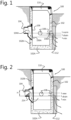
- FIG. 6 shows schematically a sectional view along VI-VI in Fig. 5 and Fig. 7 shows schematically a sectional view along VII-VII in Fig. 6 .
- the sewer outlet 104 has a first radius and each of the infiltration outlets have a second radius, wherein the second radius is smaller than the first radius.
- the openings in the gulley pot 102 forming the infiltration outlets 108 might be used to position a filter element.
- the filter element is configured to prevent that the porous layer attached to the outer surface of the gulley pot gets blocked by dirt that flows into the gulley.
- the filter element could be a replaceable filter element.
- the filter element is made from pervious concrete obtained by a mixture of epoxy mortar and sand with a grainsize of 0,6 - 1,2mm. The openings through the gulley pot for the infiltration outlets are filled with said mixture. The filter element is thus made of finer gravel than the gravel of the porous layer.
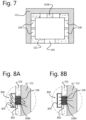
- Figs 8A and 8B show schematically a section view of two states of an embodiment of another embodiment of a filter element 800.
- the filter element is a replaceable filter element.
- the filter element 800 comprises a material 802 that is impermeable for oil and permeable for water.
- the filter element 800 comprises a check valve arrangement which opens when water pressure in the gulley pot acting on the shutters is higher than the water pressure acting on the other side of the shutters and which closes when the water pressure acting on the other side of the shutters is higher than the water pressure acting on the side facing the inside of the gulley pot 102.
- the shutters prevent groundwater to flow into the gulley pot. In this way, ground water is blocked to flow through the gulley into the storm water drainage system or sewer system that when the ground water level is higher than the level L drain .
- the drainage means 112 are a porous layer 112 attached to at least one side wall of the gulley pot and wherein the porous layer extends fully across the hole in the sidewall of the gulley pot for the at least one infiltration outlet. Furthermore, it is shown that the porous layer might extend along a bottom wall of the gulley pot. In an embodiment the porous layer is a layer of pervious concrete. It might be clear that other materials can be used that have the characteristics of permeable for water and capacity to store temporarily an amount of water to be absorbed by the soil abutting the porous layer. Furthermore, the material of the layer should be strong enough to withstand the pressure of the soil acting on the outer surface of the layer.
- the drainage means is a plastic tray with reinforcement ribs in which the gulley is placed and where the outer wall is perforated.
- the reinforcement ribs function as spacers between the outer wall and gulley pot.
- the space between the outer wall and the gulley pot forms the cavity to buffer rain water before it is absorbed by the soil surrounding the gulley pot.
- the drainage means configured to transfer water from the gulley pot to the ground around the gulley.
- infiltration pipes, perforated ducts and infiltration boxes could be coupled to the infiltration outlets.
- the pipes or tubes might be twisted around the gully pot.
- the pipes or tubes extend horizontally or slope downward away from the gulley pot to enlarge the ground surface that could absorb directly water coming from the gully pot.
- the space in the tubes will function as buffer to store temporarily rain water before it infiltrates the soil around the tubes or pipes.
- the buffer to temporarily store rain water before it infiltrates the soil around the gulley pot can be extended by channels in the ground, which adjoin the porous layer affixed to the outside of the gulley pot.
- the channels should preferably be filled with broken stone with a grainsize of 7-32mm, wherein the channel of broken stones is encapsulated by PE filter fabric.
Landscapes
- Health & Medical Sciences (AREA)
- Life Sciences & Earth Sciences (AREA)
- Engineering & Computer Science (AREA)
- Hydrology & Water Resources (AREA)
- Public Health (AREA)
- Water Supply & Treatment (AREA)
- Sewage (AREA)
Claims (15)
- Puisard (100) comprenant un pot de puisard (102), une sortie d'égout (104) dans une paroi latérale du pot de puisard et un déflecteur (106) conçu pour agir comme piège à odeurs, la sortie d'égout étant conçue pour accoupler le puisard à un système d'égout et ayant une face inférieure (104A) définissant un niveau d'écoulement sortant normal Lnorm, et le déflecteur ayant une face inférieure (106A) définissant un niveau de liquide minimal Lmin pour permettre au déflecteur d'agir comme piège à odeurs ;le pot de puisard comprenant en outre un réservoir supplémentaire sous la forme d'un moyen de drainage (112), et au moins une sortie d'infiltration (108) à travers la paroi latérale, caractérisé en ce que,l'au moins une sortie d'infiltration (108) est conçue pour transférer le liquide dans le pot de puisard vers le moyen de drainage (112) facilitant l'infiltration de l'eau collectée dans le sol autour du puisard lorsque le niveau de liquide dans le pot de puisard dépasse un niveau d'écoulement sortant supplémentaire Ldrain, où Lmin < Ldrain ≤ Lnorm.
- Puisard selon la revendication 1, le puisard comprenant en outre une partie d'insertion (214) conçue pour être insérée dans la sortie d'égout et conçue en outre pour augmenter le niveau d'écoulement sortant de liquide Lnorm pour le liquide dans le puisard vers le système d'égout à un nouveau niveau d'écoulement sortant Lnew, où Lnorm < Lnew.
- Puisard selon la revendication 2, la sortie d'égout ayant une hauteur H, et H/3 < (Lnew - Lnorm) < H/2.
- Puisard selon l'une quelconque des revendications 2 - 3, la partie d'insertion étant une partie amovible.
- Puisard selon l'une quelconque des revendications 1 - 4, le puisard comprenant un élément filtrant positionné dans chacune de l'au moins une sortie d'infiltration.
- Puisard selon la revendication 5, l'élément filtrant comprenant une couche de béton perméable disposée dans une ouverture à travers la paroi latérale du pot de puisard pour la sortie d'infiltration (108).
- Puisard selon l'une quelconque des revendications 5 - 6, l'élément filtrant comprenant un matériau qui est imperméable à l'huile et perméable à l'eau.
- Puisard selon l'une quelconque des revendications 5 - 7, l'élément filtrant comprenant en outre un dispositif de clapet de retenue conçu pour empêcher le liquide de s'écouler à travers une sortie d'infiltration dans le pot de puisard.
- Puisard selon l'une quelconque des revendications 1 - 8, le moyen de drainage (112) étant une couche poreuse fixée à au moins une partie de la surface extérieure de la paroi latérale du pot de puisard, et la couche poreuse s'étendant sur les ouvertures de l'au moins une sortie d'infiltration et éventuellement le long d'une paroi inférieure du pot de puisard.
- Puisard selon la revendication 9, la couche poreuse fixée à au moins une partie de la surface extérieure de la paroi latérale du pot de puisard étant une couche de béton perméable.
- Puisard selon la revendication 10 en liaison avec la revendication 6, la couche de béton perméable de l'élément filtrant étant constituée de gravier plus fin que le gravier de la couche poreuse fixée à la surface extérieure de la paroi latérale.
- Puisard selon l'une quelconque des revendications 9 - 11, la couche poreuse fixée à au moins une partie de la surface extérieure de la paroi latérale du pot de puisard ayant une épaisseur d'au moins 4 cm, en particulier de 6 cm.
- Puisard selon l'une quelconque des revendications 1 - 12, la sortie (104) ayant un premier rayon et chacune de l'au moins une sortie d'infiltration (108) ayant un second rayon, le second rayon étant inférieur au premier rayon.
- Puisard selon l'une quelconque des revendications 1 - 13, le puisard comprenant un moyen de drainage accouplé à l'au moins une sortie d'infiltration (108), le moyen de drainage étant conçu pour transférer du liquide depuis le pot de puisard pour infiltrer le sol autour du puisard.
- Puisard selon la revendication 14, le moyen de drainage comprenant au moins l'un des éléments suivants : tuyaux d'infiltration, conduits perforés et boîte d'infiltration.
Applications Claiming Priority (1)
| Application Number | Priority Date | Filing Date | Title |
|---|---|---|---|
| NL2022311A NL2022311B1 (en) | 2018-12-24 | 2018-12-24 | Gulley |
Publications (2)
| Publication Number | Publication Date |
|---|---|
| EP3674493A1 EP3674493A1 (fr) | 2020-07-01 |
| EP3674493B1 true EP3674493B1 (fr) | 2023-06-07 |
Family
ID=65031745
Family Applications (1)
| Application Number | Title | Priority Date | Filing Date |
|---|---|---|---|
| EP19219711.9A Active EP3674493B1 (fr) | 2018-12-24 | 2019-12-24 | Puisard |
Country Status (2)
| Country | Link |
|---|---|
| EP (1) | EP3674493B1 (fr) |
| NL (1) | NL2022311B1 (fr) |
Families Citing this family (4)
| Publication number | Priority date | Publication date | Assignee | Title |
|---|---|---|---|---|
| US10968616B1 (en) * | 2019-05-08 | 2021-04-06 | Subsurface Systems, LLC | Water drainage system |
| US20250019957A1 (en) | 2021-12-03 | 2025-01-16 | Rockwool A/S | Storm Water Filtration System |
| CN114922277B (zh) * | 2022-05-31 | 2025-10-17 | 湖南省交通规划勘察设计院有限公司 | 一种用于城市道路的海绵型边沟结构 |
| NL2036008B1 (en) | 2023-10-11 | 2025-04-28 | Gerhard Nicolaas Schotanus Jacobus | Gulley |
Family Cites Families (12)
| Publication number | Priority date | Publication date | Assignee | Title |
|---|---|---|---|---|
| NL100561C (fr) | ||||
| SE384703B (sv) * | 1975-05-23 | 1976-05-17 | Spanberg B | Anordning vid avloppsbrunnar |
| NL1005621C2 (nl) | 1997-03-25 | 1999-11-24 | Tbs Soest Bv | Aansluiting voor een kolk |
| DE10348520B4 (de) * | 2003-10-18 | 2007-04-19 | Funke Kunststoffe Gmbh | Filter für mit Metall-Ionen beladene Wässer |
| FR2903433A1 (fr) * | 2006-07-07 | 2008-01-11 | Jean Paul Rey | Dispositif d'humidification des sols de constructions |
| KR100939173B1 (ko) * | 2009-10-19 | 2010-01-28 | 유흥식 | 홍수, 가뭄, 지구 온난화, 사막화, 해수면 상승 방지 및 토양지하수 복원을 위한 초고속 투수성 블록 도로포장 시스템과 그 시공 방법 |
| NL2004578C2 (en) | 2010-04-20 | 2011-10-21 | Gemeente Amsterdam | Improved gulley. |
| KR20140126467A (ko) * | 2013-04-23 | 2014-10-31 | 주식회사 퍼팩트 | 시공 및 유지관리가 용이한 오수받이 하부 구조 |
| EP2796628B1 (fr) | 2013-04-24 | 2019-11-06 | D & B Ingenieurs B.V. | Bonde améliorée |
| CN106219758A (zh) * | 2016-08-19 | 2016-12-14 | 黄河勘测规划设计有限公司 | 适于河流及湖泊滨水带生态修复与水质净化的护岸结构 |
| CN206205290U (zh) * | 2016-11-29 | 2017-05-31 | 胡世琴 | 一种屋面雨水收集处理系统 |
| CN207062678U (zh) * | 2017-05-03 | 2018-03-02 | 刘鸿斌 | 一种市政道路排水结构 |
-
2018
- 2018-12-24 NL NL2022311A patent/NL2022311B1/en not_active IP Right Cessation
-
2019
- 2019-12-24 EP EP19219711.9A patent/EP3674493B1/fr active Active
Also Published As
| Publication number | Publication date |
|---|---|
| NL2022311B1 (en) | 2020-07-21 |
| EP3674493A1 (fr) | 2020-07-01 |
Similar Documents
| Publication | Publication Date | Title |
|---|---|---|
| EP3674493B1 (fr) | Puisard | |
| KR100952192B1 (ko) | 우수를 지중에 침투 저장하는 침투 관정을 이용한 워터 포켓 | |
| JP4891399B2 (ja) | 除塵管理枡 | |
| US20250092659A1 (en) | Underground stormwater storage system | |
| CA3141832A1 (fr) | Systeme de stockage d'eau de pluie souterrain | |
| KR100976853B1 (ko) | 집수정 | |
| US7614192B2 (en) | Building drainage system | |
| KR100842368B1 (ko) | 통합형 우수겸용 오수받이 | |
| KR101626502B1 (ko) | 막힘 방지 도로 배수시설 | |
| JP4445168B2 (ja) | 雨水浸透システム | |
| KR100918431B1 (ko) | 악취방지 빗물받이 및 그 시공방법 | |
| JPH10102573A (ja) | 貯留槽を兼ねる浸透桝 | |
| KR100898839B1 (ko) | 초기 강우 유출 조절장치 | |
| JP2008267023A (ja) | 雨水貯留システム | |
| JP6393379B1 (ja) | 縦型雨水浸透施設 | |
| CZ8661U1 (cs) | Vsakovací jímka | |
| JPS6233805Y2 (fr) | ||
| EP4538472A1 (fr) | Puisard | |
| JP2009074285A (ja) | 雨水貯留浸透施設への雨水供給配管構造 | |
| JP5033406B2 (ja) | 雨水流出抑制施設 | |
| KR20100039086A (ko) | 분리가능한 투수부재를 갖는 우수받이 | |
| KR100715445B1 (ko) | 높이조절이 가능한 통합형 우수 겸용 오수받이 | |
| JPH0613870Y2 (ja) | 雨水浸透桝 | |
| KR102822205B1 (ko) | 보도형 침투 저류 시설과 보도형 침투 저류조 및 이의 시공 방법 | |
| KR102789970B1 (ko) | 횡단보도 환경개선 빗물받이 및 그 시공방법 |
Legal Events
| Date | Code | Title | Description |
|---|---|---|---|
| PUAI | Public reference made under article 153(3) epc to a published international application that has entered the european phase |
Free format text: ORIGINAL CODE: 0009012 |
|
| STAA | Information on the status of an ep patent application or granted ep patent |
Free format text: STATUS: THE APPLICATION HAS BEEN PUBLISHED |
|
| AK | Designated contracting states |
Kind code of ref document: A1 Designated state(s): AL AT BE BG CH CY CZ DE DK EE ES FI FR GB GR HR HU IE IS IT LI LT LU LV MC MK MT NL NO PL PT RO RS SE SI SK SM TR |
|
| AX | Request for extension of the european patent |
Extension state: BA ME |
|
| STAA | Information on the status of an ep patent application or granted ep patent |
Free format text: STATUS: REQUEST FOR EXAMINATION WAS MADE |
|
| 17P | Request for examination filed |
Effective date: 20210111 |
|
| RBV | Designated contracting states (corrected) |
Designated state(s): AL AT BE BG CH CY CZ DE DK EE ES FI FR GB GR HR HU IE IS IT LI LT LU LV MC MK MT NL NO PL PT RO RS SE SI SK SM TR |
|
| GRAP | Despatch of communication of intention to grant a patent |
Free format text: ORIGINAL CODE: EPIDOSNIGR1 |
|
| STAA | Information on the status of an ep patent application or granted ep patent |
Free format text: STATUS: GRANT OF PATENT IS INTENDED |
|
| INTG | Intention to grant announced |
Effective date: 20220914 |
|
| GRAS | Grant fee paid |
Free format text: ORIGINAL CODE: EPIDOSNIGR3 |
|
| RAP3 | Party data changed (applicant data changed or rights of an application transferred) |
Owner name: VAN NULAND, FRANCISCUS HENDRICUS Owner name: SCHOTANUS, JACOBUS GERHARD NICOLAAS Owner name: J.C. WILLEMSEN BEHEER B.V. |
|
| RIN1 | Information on inventor provided before grant (corrected) |
Inventor name: WILLEMSEN, JOHANNES CORNELIS Inventor name: VAN NULAND, FRANCISCUS HENDRICUS Inventor name: SCHOTANUS, JACOBUS GERHARD NICOLAAS |
|
| GRAA | (expected) grant |
Free format text: ORIGINAL CODE: 0009210 |
|
| STAA | Information on the status of an ep patent application or granted ep patent |
Free format text: STATUS: THE PATENT HAS BEEN GRANTED |
|
| AK | Designated contracting states |
Kind code of ref document: B1 Designated state(s): AL AT BE BG CH CY CZ DE DK EE ES FI FR GB GR HR HU IE IS IT LI LT LU LV MC MK MT NL NO PL PT RO RS SE SI SK SM TR |
|
| REG | Reference to a national code |
Ref country code: GB Ref legal event code: FG4D |
|
| REG | Reference to a national code |
Ref country code: CH Ref legal event code: EP Ref country code: AT Ref legal event code: REF Ref document number: 1575409 Country of ref document: AT Kind code of ref document: T Effective date: 20230615 Ref country code: DE Ref legal event code: R096 Ref document number: 602019029978 Country of ref document: DE |
|
| REG | Reference to a national code |
Ref country code: NL Ref legal event code: FP |
|
| REG | Reference to a national code |
Ref country code: LT Ref legal event code: MG9D |
|
| PG25 | Lapsed in a contracting state [announced via postgrant information from national office to epo] |
Ref country code: SE Free format text: LAPSE BECAUSE OF FAILURE TO SUBMIT A TRANSLATION OF THE DESCRIPTION OR TO PAY THE FEE WITHIN THE PRESCRIBED TIME-LIMIT Effective date: 20230607 Ref country code: NO Free format text: LAPSE BECAUSE OF FAILURE TO SUBMIT A TRANSLATION OF THE DESCRIPTION OR TO PAY THE FEE WITHIN THE PRESCRIBED TIME-LIMIT Effective date: 20230907 Ref country code: ES Free format text: LAPSE BECAUSE OF FAILURE TO SUBMIT A TRANSLATION OF THE DESCRIPTION OR TO PAY THE FEE WITHIN THE PRESCRIBED TIME-LIMIT Effective date: 20230607 |
|
| REG | Reference to a national code |
Ref country code: AT Ref legal event code: MK05 Ref document number: 1575409 Country of ref document: AT Kind code of ref document: T Effective date: 20230607 |
|
| PG25 | Lapsed in a contracting state [announced via postgrant information from national office to epo] |
Ref country code: RS Free format text: LAPSE BECAUSE OF FAILURE TO SUBMIT A TRANSLATION OF THE DESCRIPTION OR TO PAY THE FEE WITHIN THE PRESCRIBED TIME-LIMIT Effective date: 20230607 Ref country code: LV Free format text: LAPSE BECAUSE OF FAILURE TO SUBMIT A TRANSLATION OF THE DESCRIPTION OR TO PAY THE FEE WITHIN THE PRESCRIBED TIME-LIMIT Effective date: 20230607 Ref country code: LT Free format text: LAPSE BECAUSE OF FAILURE TO SUBMIT A TRANSLATION OF THE DESCRIPTION OR TO PAY THE FEE WITHIN THE PRESCRIBED TIME-LIMIT Effective date: 20230607 Ref country code: HR Free format text: LAPSE BECAUSE OF FAILURE TO SUBMIT A TRANSLATION OF THE DESCRIPTION OR TO PAY THE FEE WITHIN THE PRESCRIBED TIME-LIMIT Effective date: 20230607 Ref country code: GR Free format text: LAPSE BECAUSE OF FAILURE TO SUBMIT A TRANSLATION OF THE DESCRIPTION OR TO PAY THE FEE WITHIN THE PRESCRIBED TIME-LIMIT Effective date: 20230908 |
|
| REG | Reference to a national code |
Ref country code: NL Ref legal event code: PD Owner name: FRANCISCUS HENDRICUS VAN NULAND; NL Free format text: DETAILS ASSIGNMENT: CHANGE OF OWNER(S), ASSIGNMENT; FORMER OWNER NAME: VAN NULAND, FRANCISCUS HENDRICUS Effective date: 20231201 |
|
| PG25 | Lapsed in a contracting state [announced via postgrant information from national office to epo] |
Ref country code: FI Free format text: LAPSE BECAUSE OF FAILURE TO SUBMIT A TRANSLATION OF THE DESCRIPTION OR TO PAY THE FEE WITHIN THE PRESCRIBED TIME-LIMIT Effective date: 20230607 |
|
| PG25 | Lapsed in a contracting state [announced via postgrant information from national office to epo] |
Ref country code: SK Free format text: LAPSE BECAUSE OF FAILURE TO SUBMIT A TRANSLATION OF THE DESCRIPTION OR TO PAY THE FEE WITHIN THE PRESCRIBED TIME-LIMIT Effective date: 20230607 |
|
| PG25 | Lapsed in a contracting state [announced via postgrant information from national office to epo] |
Ref country code: IS Free format text: LAPSE BECAUSE OF FAILURE TO SUBMIT A TRANSLATION OF THE DESCRIPTION OR TO PAY THE FEE WITHIN THE PRESCRIBED TIME-LIMIT Effective date: 20231007 |
|
| RAP2 | Party data changed (patent owner data changed or rights of a patent transferred) |
Owner name: VAN NULAND, FRANCISCUS HENDRICUS Owner name: SCHOTANUS, JACOBUS GERHARD NICOLAAS Owner name: WILLEMSEN INFRA B.V. |
|
| PG25 | Lapsed in a contracting state [announced via postgrant information from national office to epo] |
Ref country code: SM Free format text: LAPSE BECAUSE OF FAILURE TO SUBMIT A TRANSLATION OF THE DESCRIPTION OR TO PAY THE FEE WITHIN THE PRESCRIBED TIME-LIMIT Effective date: 20230607 Ref country code: SK Free format text: LAPSE BECAUSE OF FAILURE TO SUBMIT A TRANSLATION OF THE DESCRIPTION OR TO PAY THE FEE WITHIN THE PRESCRIBED TIME-LIMIT Effective date: 20230607 Ref country code: RO Free format text: LAPSE BECAUSE OF FAILURE TO SUBMIT A TRANSLATION OF THE DESCRIPTION OR TO PAY THE FEE WITHIN THE PRESCRIBED TIME-LIMIT Effective date: 20230607 Ref country code: PT Free format text: LAPSE BECAUSE OF FAILURE TO SUBMIT A TRANSLATION OF THE DESCRIPTION OR TO PAY THE FEE WITHIN THE PRESCRIBED TIME-LIMIT Effective date: 20231009 Ref country code: IS Free format text: LAPSE BECAUSE OF FAILURE TO SUBMIT A TRANSLATION OF THE DESCRIPTION OR TO PAY THE FEE WITHIN THE PRESCRIBED TIME-LIMIT Effective date: 20231007 Ref country code: EE Free format text: LAPSE BECAUSE OF FAILURE TO SUBMIT A TRANSLATION OF THE DESCRIPTION OR TO PAY THE FEE WITHIN THE PRESCRIBED TIME-LIMIT Effective date: 20230607 Ref country code: CZ Free format text: LAPSE BECAUSE OF FAILURE TO SUBMIT A TRANSLATION OF THE DESCRIPTION OR TO PAY THE FEE WITHIN THE PRESCRIBED TIME-LIMIT Effective date: 20230607 Ref country code: AT Free format text: LAPSE BECAUSE OF FAILURE TO SUBMIT A TRANSLATION OF THE DESCRIPTION OR TO PAY THE FEE WITHIN THE PRESCRIBED TIME-LIMIT Effective date: 20230607 |
|
| PG25 | Lapsed in a contracting state [announced via postgrant information from national office to epo] |
Ref country code: PL Free format text: LAPSE BECAUSE OF FAILURE TO SUBMIT A TRANSLATION OF THE DESCRIPTION OR TO PAY THE FEE WITHIN THE PRESCRIBED TIME-LIMIT Effective date: 20230607 |
|
| REG | Reference to a national code |
Ref country code: DE Ref legal event code: R097 Ref document number: 602019029978 Country of ref document: DE |
|
| PLBE | No opposition filed within time limit |
Free format text: ORIGINAL CODE: 0009261 |
|
| STAA | Information on the status of an ep patent application or granted ep patent |
Free format text: STATUS: NO OPPOSITION FILED WITHIN TIME LIMIT |
|
| PG25 | Lapsed in a contracting state [announced via postgrant information from national office to epo] |
Ref country code: DK Free format text: LAPSE BECAUSE OF FAILURE TO SUBMIT A TRANSLATION OF THE DESCRIPTION OR TO PAY THE FEE WITHIN THE PRESCRIBED TIME-LIMIT Effective date: 20230607 |
|
| PG25 | Lapsed in a contracting state [announced via postgrant information from national office to epo] |
Ref country code: SI Free format text: LAPSE BECAUSE OF FAILURE TO SUBMIT A TRANSLATION OF THE DESCRIPTION OR TO PAY THE FEE WITHIN THE PRESCRIBED TIME-LIMIT Effective date: 20230607 |
|
| 26N | No opposition filed |
Effective date: 20240308 |
|
| PG25 | Lapsed in a contracting state [announced via postgrant information from national office to epo] |
Ref country code: SI Free format text: LAPSE BECAUSE OF FAILURE TO SUBMIT A TRANSLATION OF THE DESCRIPTION OR TO PAY THE FEE WITHIN THE PRESCRIBED TIME-LIMIT Effective date: 20230607 Ref country code: IT Free format text: LAPSE BECAUSE OF FAILURE TO SUBMIT A TRANSLATION OF THE DESCRIPTION OR TO PAY THE FEE WITHIN THE PRESCRIBED TIME-LIMIT Effective date: 20230607 |
|
| REG | Reference to a national code |
Ref country code: CH Ref legal event code: PL |
|
| PG25 | Lapsed in a contracting state [announced via postgrant information from national office to epo] |
Ref country code: MC Free format text: LAPSE BECAUSE OF FAILURE TO SUBMIT A TRANSLATION OF THE DESCRIPTION OR TO PAY THE FEE WITHIN THE PRESCRIBED TIME-LIMIT Effective date: 20230607 |
|
| GBPC | Gb: european patent ceased through non-payment of renewal fee |
Effective date: 20231224 |
|
| PG25 | Lapsed in a contracting state [announced via postgrant information from national office to epo] |
Ref country code: MC Free format text: LAPSE BECAUSE OF FAILURE TO SUBMIT A TRANSLATION OF THE DESCRIPTION OR TO PAY THE FEE WITHIN THE PRESCRIBED TIME-LIMIT Effective date: 20230607 |
|
| REG | Reference to a national code |
Ref country code: IE Ref legal event code: MM4A |
|
| PG25 | Lapsed in a contracting state [announced via postgrant information from national office to epo] |
Ref country code: IE Free format text: LAPSE BECAUSE OF NON-PAYMENT OF DUE FEES Effective date: 20231224 |
|
| PG25 | Lapsed in a contracting state [announced via postgrant information from national office to epo] |
Ref country code: GB Free format text: LAPSE BECAUSE OF NON-PAYMENT OF DUE FEES Effective date: 20231224 |
|
| PG25 | Lapsed in a contracting state [announced via postgrant information from national office to epo] |
Ref country code: FR Free format text: LAPSE BECAUSE OF NON-PAYMENT OF DUE FEES Effective date: 20231231 |
|
| PG25 | Lapsed in a contracting state [announced via postgrant information from national office to epo] |
Ref country code: CH Free format text: LAPSE BECAUSE OF NON-PAYMENT OF DUE FEES Effective date: 20231231 |
|
| PG25 | Lapsed in a contracting state [announced via postgrant information from national office to epo] |
Ref country code: IE Free format text: LAPSE BECAUSE OF NON-PAYMENT OF DUE FEES Effective date: 20231224 Ref country code: GB Free format text: LAPSE BECAUSE OF NON-PAYMENT OF DUE FEES Effective date: 20231224 Ref country code: FR Free format text: LAPSE BECAUSE OF NON-PAYMENT OF DUE FEES Effective date: 20231231 Ref country code: CH Free format text: LAPSE BECAUSE OF NON-PAYMENT OF DUE FEES Effective date: 20231231 |
|
| PG25 | Lapsed in a contracting state [announced via postgrant information from national office to epo] |
Ref country code: BG Free format text: LAPSE BECAUSE OF FAILURE TO SUBMIT A TRANSLATION OF THE DESCRIPTION OR TO PAY THE FEE WITHIN THE PRESCRIBED TIME-LIMIT Effective date: 20230607 |
|
| PG25 | Lapsed in a contracting state [announced via postgrant information from national office to epo] |
Ref country code: BG Free format text: LAPSE BECAUSE OF FAILURE TO SUBMIT A TRANSLATION OF THE DESCRIPTION OR TO PAY THE FEE WITHIN THE PRESCRIBED TIME-LIMIT Effective date: 20230607 |
|
| PG25 | Lapsed in a contracting state [announced via postgrant information from national office to epo] |
Ref country code: CY Free format text: LAPSE BECAUSE OF FAILURE TO SUBMIT A TRANSLATION OF THE DESCRIPTION OR TO PAY THE FEE WITHIN THE PRESCRIBED TIME-LIMIT; INVALID AB INITIO Effective date: 20191224 |
|
| PG25 | Lapsed in a contracting state [announced via postgrant information from national office to epo] |
Ref country code: HU Free format text: LAPSE BECAUSE OF FAILURE TO SUBMIT A TRANSLATION OF THE DESCRIPTION OR TO PAY THE FEE WITHIN THE PRESCRIBED TIME-LIMIT; INVALID AB INITIO Effective date: 20191224 |
|
| PG25 | Lapsed in a contracting state [announced via postgrant information from national office to epo] |
Ref country code: TR Free format text: LAPSE BECAUSE OF FAILURE TO SUBMIT A TRANSLATION OF THE DESCRIPTION OR TO PAY THE FEE WITHIN THE PRESCRIBED TIME-LIMIT Effective date: 20230607 |
|
| PGFP | Annual fee paid to national office [announced via postgrant information from national office to epo] |
Ref country code: LU Payment date: 20251117 Year of fee payment: 7 Ref country code: NL Payment date: 20251103 Year of fee payment: 7 |
|
| REG | Reference to a national code |
Ref country code: NL Ref legal event code: PD Owner name: FRANCISCUS HENDRICUS VAN NULAND; NL Free format text: DETAILS ASSIGNMENT: CHANGE OF OWNER(S), ASSIGNMENT; FORMER OWNER NAME: WILLEMSEN INFRA B.V. Effective date: 20251222 |
|
| PGFP | Annual fee paid to national office [announced via postgrant information from national office to epo] |
Ref country code: DE Payment date: 20251117 Year of fee payment: 7 |
|
| PGFP | Annual fee paid to national office [announced via postgrant information from national office to epo] |
Ref country code: BE Payment date: 20251118 Year of fee payment: 7 |