EP3674495B1 - Disposition du coffrage et de l'armature - Google Patents
Disposition du coffrage et de l'armature Download PDFInfo
- Publication number
- EP3674495B1 EP3674495B1 EP19215488.8A EP19215488A EP3674495B1 EP 3674495 B1 EP3674495 B1 EP 3674495B1 EP 19215488 A EP19215488 A EP 19215488A EP 3674495 B1 EP3674495 B1 EP 3674495B1
- Authority
- EP
- European Patent Office
- Prior art keywords
- shuttering
- spacer
- reinforcement
- arrangement according
- grout
- Prior art date
- Legal status (The legal status is an assumption and is not a legal conclusion. Google has not performed a legal analysis and makes no representation as to the accuracy of the status listed.)
- Active
Links
Images


Classifications
-
- E—FIXED CONSTRUCTIONS
- E04—BUILDING
- E04C—STRUCTURAL ELEMENTS; BUILDING MATERIALS
- E04C5/00—Reinforcing elements, e.g. for concrete; Auxiliary elements therefor
- E04C5/16—Auxiliary parts for reinforcements, e.g. connectors, spacers, stirrups
- E04C5/168—Spacers connecting parts for reinforcements and spacing the reinforcements from the form
-
- E—FIXED CONSTRUCTIONS
- E04—BUILDING
- E04B—GENERAL BUILDING CONSTRUCTIONS; WALLS, e.g. PARTITIONS; ROOFS; FLOORS; CEILINGS; INSULATION OR OTHER PROTECTION OF BUILDINGS
- E04B1/00—Constructions in general; Structures which are not restricted either to walls, e.g. partitions, or floors or ceilings or roofs
- E04B1/62—Insulation or other protection; Elements or use of specified material therefor
- E04B1/66—Sealings
- E04B1/68—Sealings of joints, e.g. expansion joints
- E04B1/6807—Expansion elements for parts cast in situ
Definitions
- the present invention relates to a spacer for concrete construction for use between a formwork or a floor surface and a reinforcement element in the area of a formwork wall, in particular a partially permeable formwork wall, the spacer comprising a contact surface for arrangement on the formwork or floor surface, and a support for the reinforcement element.
- the invention also relates to a formwork and reinforcement arrangement with a corresponding spacer.
- a formwork element for a corresponding formwork wall which has a concrete cover strip in its lower section, which can act as a spacer in order to keep the reinforcement in the intended position.
- More spacers are from the DE 19 58 266 U known, in which case, for example, parallel retaining walls can form a support for reinforcing bars.
- the retaining walls are connected by a gutter with vent holes to allow the liquid concrete to fill in the areas above and below the gutter.
- the KR 101785721 B1 discloses spacers on which carriers can be placed.
- the AU 4438293A discloses an elongate member cast into a cast concrete slab to form a frangible link
- the object of the present invention is to provide an easy-to-handle, reliable and effective design of a spacer which can prevent or at least reduce contamination when concreting in certain areas.
- a formwork and reinforcement arrangement for concrete construction according to claim 1 is provided. This makes it possible to prevent leaking slurry from flowing onto the formwork or floor surface. Rather, the stillage is at least largely caught in the stillage collecting element.
- the slag collecting element is part of the spacer and is therefore arranged directly in the area of the partially permeable formwork wall. The stillage is thus caught in the area where it is produced.
- the formwork wall is in particular an expanded metal mesh, a perforated sheet metal or the like.
- the stillage is formed in particular by liquid concrete components which emerge from the concrete during the concreting of a concreting section and then flow off in particular through the formwork walls. The stillage thus flows through the openings in the formwork wall and then down the formwork wall.
- the stillage flows in the area of the spacer onto the formwork or floor surface and contaminates it.
- the stillage is now collected directly in the area in which it is produced.
- the formwork wall can also be an impermeable, flat component, for example a fully closed metal sheet. Nevertheless, stillage can escape in the edge areas, especially in the lower area between the spacer and the formwork wall.
- the stillage catch element enables the stillage to be collected.
- the reinforcement element is in particular at least one reinforcement bar made of metal.
- the reinforcement element can be a plurality of reinforcement rods arranged in the form of a lattice, optionally connected to one another.
- the sludge catching element is arranged next to the support of the spacer, particularly advantageously directly next to the support.
- the formwork wall is advantageously arranged in the area of the support. Since the formwork wall is connected to the reinforcement elements, this arrangement enables the weight of the formwork wall to be advantageously supported and thus gives the overall arrangement additional stability. At the same time, this means that the slurry catching element is arranged next to the support directly under the formwork wall and can collect concrete slurry that is flowing off.
- the support can be arranged between two stillage collecting elements. This is particularly advantageous since it is now arbitrary whether the formwork wall is arranged on the left or right next to the support, since sludge collecting elements are provided on both sides. As a result, errors in the specific arrangement of the spacers on the construction site can be avoided, which means that costly follow-up checks and improvements can be avoided.
- the sludge catching element is designed in the form of a channel or trough that is primarily closed continuously at the bottom.
- the tub can be closed off at its end face.
- the channel can also lead to an area outside the next concreting section, so that the slurry can be discharged to non-critical areas.
- only collecting surfaces which can be arranged straight or inclined, can be provided.
- the catchment areas can either be large enough to collect the stillage or allow the stillage to flow off into non-critical areas.
- the slag collecting element is designed in such a way that it can collect or discharge slag produced on a formwork wall when concreting a first concrete section in such a way that it does not contaminate an adjacent, second concrete section to be concreted later.
- the sludge catching element is formed at an acute angle in its lower area, so that the contact area is formed by a line. This allows the spacer to be enclosed except for the linear abutment area of concrete, thereby minimizing the exposed area of the spacer. Minimizing the exposed area is advantageous as this remains visible after the pouring sections have been completed and may need to be protected from corrosion.
- the linear contact area can be provided in particular by a kink in the spacer.
- the spacer is formed by a metal sheet, with the kink being formed by forming between two boundary surfaces of the metal sheet.
- the spacer comprises two flat flange areas which are each arranged at the same height, the flange areas being connected by two boundary surfaces arranged in a V-shape, the connection point of which forms the linear contact area.
- the slop collecting element has a base plate and side walls arranged on both sides thereof. This enables a simple design of the sludge catching element and an advantageous integration into the spacer, since, for example, the base plate can simultaneously form a contact surface for the spacer.
- At least one side wall of the sludge catching element can advantageously provide the support for the reinforcement element. This means that the reinforcement element or the reinforcement rod is placed on the side wall of the slop collecting element, which thus provides the function of the spacer.
- the support is advantageously formed by a recess in a wall of the spacer.
- the recess is in particular a slit open at the top, the sides of which extend in parallel, advantageously in the vertical direction.
- the sides of the slot are spaced slightly greater than the diameter of the rebars.
- a rounding can be provided, which has a radius of curvature that essentially corresponds to half the diameter of the reinforcing rods. A safe and defined support of the reinforcing bar can thus be achieved.
- the spacer is a bent piece of metal plate. This enables simple production and also advantageous stability.
- the spacer has at least two parts connected in particular by welding, one of which is a bent part and the other a plate part.
- the parts are formed from metal plates.
- a connection can also be made by gluing, soldering or screwing.
- a form fit is provided by bending.
- the bending part forms the slop collecting element, in that a channel or trough is thereby formed.
- the plate part forms a support part which is advantageously provided with the aforesaid recesses.
- the spacer has a coating at least in the contact area.
- the coating enables the spacer, which is made of metal in particular, to be protected from environmental influences, so that corrosion in particular can be prevented.
- the coating is made of plastic, in particular butyl or epoxy resin. This enables the creation of a thin yet robust coating.
- the spacer can be covered with concrete in its contact area. This enables a continuous concrete surface to be created between the concreting sections.
- the shuttering wall is connected to the reinforcement element and possibly to the spacer, for example by means of tie wires and the like.
- the formwork wall is advantageously designed as an expanded metal plate. This enables the pouring section to be sufficiently delineated so that the liquid concrete only slightly penetrates through the formwork wall but does not significantly flow out of the pouring section.
- the formwork wall is arranged essentially vertically.
- the reinforcement element extends substantially horizontally. In this way, the emerging cement slurry runs directly down the formwork wall into the slurry collecting element.
- the formwork wall and/or the reinforcement element can also be arranged at an angle. After the stillage runs down the formwork wall, it is then usually sufficient for the stillage collecting element to be arranged only at the base under the formwork wall.
- the spacer consists of a one-part or multi-part rail made of metal or plastic with a substantially L-shaped cross section, the long L-leg contains slots open at the top, which form supports for rebars with their lower ends, and whose short L-leg is bent upwards in the form of a channel to form the sludge collecting element.
- the angling of the short L-leg upwards is essentially vertical.
- the width of the sludge catching element is greater than the height of the bend in the short leg of the L.
- the short leg of the L is bent upwards to such an extent that its free edge lies in a plane with the supports, thereby forming a second support for the reinforcing bars.
- slots that are open upwards can also be provided in the bend.
- the spacer can consist of a one-piece or multi-piece rail with a substantially U-shaped cross-section, the two legs of which contain upwardly open slots that form the first and second supports for reinforcing rods with their lower ends, with the sludge collecting element passing through the middle, lower portion of the U-shaped cross-section is defined.
- the cross section of the rail can have a symmetrical shape that is mirrored around the long leg of the L as the axis of symmetry. The result of this is that the orientation of the spacer with respect to the plane of symmetry is irrelevant, as a result of which errors during installation due to incorrect orientation in this respect can be ruled out.
- the formwork wall can be an expanded metal plate.
- the formwork wall can be arranged essentially vertically.
- the spacer can be inserted between a vertical formwork and a reinforcing element, the spacer consisting of a supporting part for the reinforcing element and a spacer part for insertion between the formwork and the reinforcing element.
- the spacer part is channel-shaped in cross-section and open in the direction of the support part, and forms a contact area in the opposite direction.
- the spacer part is advantageously formed in particular by at least one boundary surface by two flat boundary surfaces delimiting the channel.
- the support part is formed in particular by at least one flange, advantageously by one flange per boundary surface.
- the spacer can be inserted between a formwork and a reinforcement element, the spacer comprising an abutment area for placement on the vertical formwork, and a support for the reinforcement element, the abutment area being linear.
- the spacer may extend in the vertical direction and the at least one reinforcement element arranged on the support of the spacer may extend in the horizontal direction.
- the invention further provides the use of a spacer in a formwork and reinforcement arrangement according to the invention for concrete construction according to claim 15 .
- FIG 1 A formwork and reinforcement arrangement according to an embodiment of the invention is shown in a side sectional view.
- the formwork and reinforcement arrangement comprises a spacer 1 , a reinforcement element 2 in the form of a reinforcement rod arranged on or in the spacer 1 , and a formwork wall 3 which is arranged over a slag collecting element 4 of the spacer 1 .
- the spacer 1 has a substantially L-shaped cross-section, with a long L-leg 5 and a short L-leg 6, with a long L-leg 5 opposite bend 7.
- the long L-leg are open at the top Slots 8 are provided which extend up to a height h1 above the lower contact area of the spacer 1.
- the height h2 of the bend 7 corresponds to the height h1.
- a horizontally arranged reinforcement element 2, in particular in the form of a reinforcement bar, can then be arranged on these supports, as in figure 1 shown.
- the formwork wall 3 is arranged on the spacer 1.
- the formwork wall can be connected to the long L-leg 5 of the spacer 1 and/or to the reinforcement elements 2 . Since the slots 8 do not extend into the lower area of the spacer 1, the long L-leg 5 in the lower area of the spacer 1 assumes the function of the formwork wall.
- the formwork wall 3 is designed in particular as an expanded metal grid or as a perforated plate.
- a fresh concrete composite foil 10 can be provided under the spacer 1 on the floor surface or the horizontal formwork 9 . This can protect the floor surface or formwork 9 from contamination. If liquid concrete is now poured into the first concreting section BA1, it fills the concreting section BA1 up to the formwork wall 3. A small part of the liquid concrete passes through the openings in the formwork wall 3 and, after hardening, forms a connecting surface for the liquid concrete subsequently poured into the concreting section BA2. If the concreting sections BA1 and BA2 are sections of a ceiling, the formwork 9 is removed after the concrete in the concreting sections BA1 and BA2 has hardened.
- closure elements for the sludge catching element can be provided at the longitudinal ends of the spacer 1, so that it has a trough-shaped structure.
- the sludge catching element can also be left open in these areas, as in FIG figure 2 shown so that the stillage can flow into areas that are not critical for contamination.
- the spacer 1 can be manufactured in particular as a bent part from a metal sheet, or as a plastic profile part.
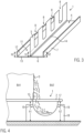
- FIG 3 a further embodiment of a spacer according to the invention is shown in a perspective view.
- slop catching elements 4, 11 are arranged symmetrically on either side of a central long leg 5 of the L.
- further supports are provided by the bends 7 and 12.
- the short L-legs 6 and 13 can be formed from just one metal sheet, which is designed as a bent part with respect to the bends 7 and 12 .
- the long leg 5 of the L can be formed as a plate part in which only the slots 8 are provided.
- the bending part and the plate part can be connected, in particular, by welding, as illustrated by the weld seam 14 .
- the formwork wall 3 can be arranged either over the short leg 6 of the L or over the short leg 13 of the L. It can thus be ensured that the slurry escaping from the formwork wall 3 is always caught by one of the slurry collecting elements 4 , 11 .
- FIG 4 a sectional view of a further embodiment of the formwork and reinforcement arrangement according to the invention is shown.
- the spacer 1 according to the invention used therein has a long leg 15 which is connected to a short leg 17 via a channel-shaped region 16 .
- the long leg 15, trough-shaped portion 16 and short leg 17 may be formed as an integral flexure.
- slits can be provided, similar to those already in figure 3 or figure 1 are shown.
- the short leg 17 can in turn be designed in such a way that the heights h1, h2 of the supports are the same.
- a reinforcement element 2 which is advantageously connected to a formwork wall 3 , is in turn placed on this support.
- the lower part of the spacer 1 is poured over with concrete before the spacer 1 is installed in the formwork and reinforcement arrangement, in order to provide a contact element 18 with a particularly level contact area.
- the uprising element 18 thus forms a concrete bar.
- fastening elements 19 can protrude from the outer wall of the channel-shaped area 16, which are cast into the support element 18 and thus enable a secure connection between the support element 18 and the channel-shaped area 16 by means of a form fit.
- a lower continuous concrete surface is formed, which is formed by the concrete in the concreting section BA1, the contact element 18 made of concrete, and the concrete in the concreting section BA2.
- the uprising element 18 can in particular be made of fiber concrete.
- a spacer 1 is shown, the sludge collecting element 4 of which is formed by two boundary surfaces 20, 21 arranged at an acute angle, so that a linear contact area 22 is formed.
- the boundary surfaces 20, 21 form a spacer part of the spacer 1.
- boundary surfaces 20, 21 are flat, so that the sludge catching element 4 is essentially in the form of a V-shaped channel.
- the boundary surfaces 20, 21 are followed by flange regions 23, 24 which extend essentially horizontally and at the same height h1, h2 and which form a bearing part.
- the support part provides a support for at least one reinforcement element 2 .
- openings 25 can be provided in the flange regions 23, 24, which enable the reinforcement elements 2 to be fastened by a fastening means, for example tie wire.
- the reinforcement element 2 is in particular a reinforcement bar.
- the spacer 1 has a substantially vertically extending receiving wall 26 in which slots 8 are provided, in which—as in the previous embodiments—the reinforcing elements 2, in particular reinforcing rods, can be received.
- FIG 6 is the use of the spacer 1 according to figure 5 shown between two concreting sections BA1, BA2. Concrete slurry escaping from the formwork wall 3 is caught in the slurry collecting element 4 .
- the spacer 1 with the flange areas 23 , 24 provides secure bearing surfaces for the reinforcement elements 2 . If the concreting sections BA1 and BA2 form a ceiling, for example, the spacer 1 is covered almost continuously by concrete from the concreting sections BA1 and BA2 and can only be seen in its linear area 22 . The spacer can thus be protected from external influences and a visually continuous ceiling can be produced.
- a wall can be concreted in which the horizontally extending reinforcing rods 2 and the vertically extending reinforcing rods 27 can be kept at a defined distance from the vertical formwork 9, whereby the area of the spacer not covered by concrete can be minimized.
- the horizontally running rebars 2 are advantageously held in the slots 8 at the desired positions.
Landscapes
- Engineering & Computer Science (AREA)
- Architecture (AREA)
- Civil Engineering (AREA)
- Structural Engineering (AREA)
- Physics & Mathematics (AREA)
- Electromagnetism (AREA)
- Forms Removed On Construction Sites Or Auxiliary Members Thereof (AREA)
- Reinforcement Elements For Buildings (AREA)
Claims (15)
- Agencement de coffrage et d'armature pour la construction en béton, qui présente un élément d'espacement (1), au moins un élément d'armature (2) et une paroi de coffrage (3), dans lequel l'élément d'espacement (1) est agencé entre un coffrage (9) ou une surface de fond et l'élément d'armature (2) dans la zone de la paroi de coffrage (3), en particulier semi-perméable, dans lequel l'élément d'espacement (1) comprend une zone d'appui destinée à être agencée sur le coffrage (9) ou la surface de fond, et un support pour l'élément d'armature (2), dans lequel au moins un élément d'armature (2) est agencé sur le support de l'élément d'espacement (1),
caractérisé par
un élément de collecte de laitance (4) qui est conçu pour collecter la laitance sortant de la paroi de coffrage (3), dans lequel la paroi de coffrage (3) est agencée sensiblement au-dessus de l'élément de collecte de laitance. - Agencement de coffrage et d'armature selon la revendication 1, dans lequel l'élément de collecte de laitance (4) est agencé à côté du support.
- Agencement de coffrage et d'armature selon la revendication 1, dans lequel le support est agencé entre deux éléments de collecte de laitance (4, 11).
- Agencement de coffrage et d'armature selon l'une quelconque des revendications précédentes, dans lequel l'élément de collecte de laitance (4, 11) est réalisé sous la forme d'une goulotte ou d'une cuve.
- Agencement de coffrage et d'armature selon l'une quelconque des revendications précédentes, dans lequel l'élément de collecte de laitance est formé à angle aigu dans sa zone inférieure de sorte que la zone d'appui est formée par une ligne.
- Agencement de coffrage et d'armature selon l'une quelconque des revendications précédentes, dans lequel l'élément de collecte de laitance (4, 11) comprend une plaque de fond et des parois latérales agencées de part et d'autre de celle-ci.
- Agencement de coffrage et d'armature selon la revendication 6, dans lequel au moins une paroi latérale de l'élément de collecte de laitance (4) fournit le support pour l'élément d'armature (2).
- Agencement de coffrage et d'armature selon l'une quelconque des revendications précédentes, dans lequel le support est formé par un évidement, en particulier une fente (8), dans une paroi de l'élément d'espacement (1).
- Agencement de coffrage et d'armature selon l'une quelconque des revendications 1 à 7, dans lequel l'élément d'espacement (1) présente au moins deux parties, en particulier reliées par soudage, dont l'une est une partie fléchie et dont l'autre est une partie de plaque.
- Agencement de coffrage et d'armature selon l'une quelconque des revendications précédentes, dans lequel l'élément d'espacement (1) présente un revêtement au moins dans sa zone d'appui.
- Agencement de coffrage et d'armature selon la revendication 10, dans lequel le revêtement est réalisé en matière plastique, en particulier en butyle ou en résine époxy.
- Agencement de coffrage et d'armature selon l'une quelconque des revendications précédentes, dans lequel l'élément d'espacement (1) est recouvert de béton dans sa zone d'appui.
- Agencement de coffrage et d'armature selon l'une quelconque des revendications précédentes, dans lequel l'élément d'espacement est constitué d'un rail en une ou plusieurs parties, fabriqué en métal ou en matière plastique, avec une section transversale sensiblement en forme de L, dont la branche de L longue (5) contient des fentes ouvertes vers le haut, qui forment des supports pour des barres d'armature avec leurs extrémités inférieures, et dont la branche de L courte (6, 13) est coudée vers le haut pour former l'élément de collecte de laitance (4) sous la forme d'une goulotte.
- Agencement de coffrage et d'armature selon l'une quelconque des revendications précédentes, dans lequel l'élément d'espacement (1) est constitué d'une partie de support pour l'élément d'armature (2) et d'une partie d'espacement destinée à être insérée entre le coffrage (9) et l'élément d'armature (2), dans lequel la partie d'espacement, en section transversale, est ouverte en forme de goulotte et en direction de la partie de support, et forme une zone d'appui (22) dans la direction opposée.
- Utilisation d'un élément d'espacement (1) dans un agencement de coffrage et d'armature pour la construction en béton selon l'une quelconque des revendications précédentes, dans laquelle l'élément d'espacement (1) est agencé entre un coffrage (9) ou une surface de fond et un élément d'armature (2) dans la zone d'une paroi de coffrage (3), en particulier semi-perméable, dans laquelle l'élément d'espacement (1) comprend une zone d'appui destinée à être agencée sur le coffrage (9) ou la surface de fond, et un support pour l'élément d'armature (2),
caractérisé par
un élément de collecte de laitance (4) qui collecte la laitance sortant de la paroi de coffrage (3).
Applications Claiming Priority (1)
| Application Number | Priority Date | Filing Date | Title |
|---|---|---|---|
| DE202018107450.4U DE202018107450U1 (de) | 2018-12-28 | 2018-12-28 | Abstabdshalter für den Betonbau mit Schlempenauffangelement |
Publications (2)
| Publication Number | Publication Date |
|---|---|
| EP3674495A1 EP3674495A1 (fr) | 2020-07-01 |
| EP3674495B1 true EP3674495B1 (fr) | 2023-07-05 |
Family
ID=65817460
Family Applications (1)
| Application Number | Title | Priority Date | Filing Date |
|---|---|---|---|
| EP19215488.8A Active EP3674495B1 (fr) | 2018-12-28 | 2019-12-12 | Disposition du coffrage et de l'armature |
Country Status (2)
| Country | Link |
|---|---|
| EP (1) | EP3674495B1 (fr) |
| DE (1) | DE202018107450U1 (fr) |
Family Cites Families (5)
| Publication number | Priority date | Publication date | Assignee | Title |
|---|---|---|---|---|
| DE1958266U (de) | 1967-01-28 | 1967-04-06 | Reuss & Co | Abstandhalter fuer bewehrungseisen. |
| CH646751A5 (de) * | 1980-05-01 | 1984-12-14 | Pawe Ag | Verwendung von aus streckmetall oder aus blech mit aufgerauhter oberflaeche bestehenden profilelementen bei der betonierung eines bauwerkes. |
| NZ243822A (en) * | 1992-08-03 | 1996-02-27 | Steel Products Ltd | Concrete slab with angular crack control element |
| EP0586867A1 (fr) | 1992-09-08 | 1994-03-16 | Peca-Verbundtechnik Gmbh | Coffrage d'about |
| KR101785721B1 (ko) * | 2016-11-22 | 2017-10-16 | 에스와이스틸텍 주식회사 | 데크플레이트용 스페이서 |
-
2018
- 2018-12-28 DE DE202018107450.4U patent/DE202018107450U1/de active Active
-
2019
- 2019-12-12 EP EP19215488.8A patent/EP3674495B1/fr active Active
Also Published As
| Publication number | Publication date |
|---|---|
| EP3674495A1 (fr) | 2020-07-01 |
| DE202018107450U1 (de) | 2019-03-07 |
Similar Documents
| Publication | Publication Date | Title |
|---|---|---|
| DE3013710C2 (de) | Vorrichtung zum Verwahren von in einer Betonwand zu verankernden Bewehrungsstäben | |
| DE9206140U1 (de) | Schalung | |
| DE102015121810A1 (de) | Schalung für eine Aufkantung | |
| DE102011088456B4 (de) | Anordnung mit Positionierungselement zum Positionieren zumindest eines stabförmigen Bewehrungselementes | |
| EP0658660A1 (fr) | Elément de construction pour isolation thermique | |
| EP2716839B1 (fr) | Elément de coffrage | |
| EP1118730A1 (fr) | Espaceur de renforcement positionnant des barres d'armature vis à vis d'un coffrage pour constructions de béton | |
| DE69512411T2 (de) | Flüssigkeitsrohr | |
| EP3674495B1 (fr) | Disposition du coffrage et de l'armature | |
| DE102013216838B3 (de) | Schalungsanordnung | |
| DE202024104862U1 (de) | Entwässerungsrinne zum Ableiten von Oberflächenwasser | |
| DE102010040663A1 (de) | Verbindungselement | |
| DE2943786C2 (de) | Vorgefertigtes montagesteifes Plattenelement zur Herstellung von Decken und Verfahren zu dessen Herstellung | |
| DE29720926U1 (de) | Abschalelement | |
| WO2004059216A1 (fr) | Element de construction prefabrique en particulier element de construction ou de paroi constitue d'un materiau durci et procede de production d'un tel element de construction | |
| DE102013207951A1 (de) | Entwässerungssystem für eine Verkehrsfläche | |
| EP0715039A1 (fr) | Elément de coffrage | |
| EP2728077B1 (fr) | Canal pour l'évacuation des eaux de surface | |
| EP2022908B1 (fr) | Coffrage frontal | |
| DE102023117193A1 (de) | Elementplatte zum Herstellen einer Halbfertigteildecke | |
| DE1229270B (de) | Stahlbetonrippendecke | |
| DE1559174C (de) | Vieleckiger Behälter, bei dem die Seitenwandung aus plattenförmigen Bauelementen aus Stahlbeton besteht | |
| DE4409782C2 (de) | Verlorene Schalung zum Betonieren eines oberen Abschlusses einer Geschoß- oder Kniestockwand | |
| AT412295B (de) | Hohlwand - verbindungsträger für vollflächiges aufbringen von wärmedämmplatten auf der innenseiteder verlorenen schalung | |
| AT404957B (de) | Bewehrungselement |
Legal Events
| Date | Code | Title | Description |
|---|---|---|---|
| PUAI | Public reference made under article 153(3) epc to a published international application that has entered the european phase |
Free format text: ORIGINAL CODE: 0009012 |
|
| STAA | Information on the status of an ep patent application or granted ep patent |
Free format text: STATUS: THE APPLICATION HAS BEEN PUBLISHED |
|
| AK | Designated contracting states |
Kind code of ref document: A1 Designated state(s): AL AT BE BG CH CY CZ DE DK EE ES FI FR GB GR HR HU IE IS IT LI LT LU LV MC MK MT NL NO PL PT RO RS SE SI SK SM TR |
|
| AX | Request for extension of the european patent |
Extension state: BA ME |
|
| STAA | Information on the status of an ep patent application or granted ep patent |
Free format text: STATUS: REQUEST FOR EXAMINATION WAS MADE |
|
| 17P | Request for examination filed |
Effective date: 20201216 |
|
| RBV | Designated contracting states (corrected) |
Designated state(s): AL AT BE BG CH CY CZ DE DK EE ES FI FR GB GR HR HU IE IS IT LI LT LU LV MC MK MT NL NO PL PT RO RS SE SI SK SM TR |
|
| GRAP | Despatch of communication of intention to grant a patent |
Free format text: ORIGINAL CODE: EPIDOSNIGR1 |
|
| STAA | Information on the status of an ep patent application or granted ep patent |
Free format text: STATUS: GRANT OF PATENT IS INTENDED |
|
| INTG | Intention to grant announced |
Effective date: 20230213 |
|
| GRAS | Grant fee paid |
Free format text: ORIGINAL CODE: EPIDOSNIGR3 |
|
| GRAA | (expected) grant |
Free format text: ORIGINAL CODE: 0009210 |
|
| STAA | Information on the status of an ep patent application or granted ep patent |
Free format text: STATUS: THE PATENT HAS BEEN GRANTED |
|
| P01 | Opt-out of the competence of the unified patent court (upc) registered |
Effective date: 20230327 |
|
| AK | Designated contracting states |
Kind code of ref document: B1 Designated state(s): AL AT BE BG CH CY CZ DE DK EE ES FI FR GB GR HR HU IE IS IT LI LT LU LV MC MK MT NL NO PL PT RO RS SE SI SK SM TR |
|
| REG | Reference to a national code |
Ref country code: CH Ref legal event code: EP |
|
| REG | Reference to a national code |
Ref country code: AT Ref legal event code: REF Ref document number: 1584971 Country of ref document: AT Kind code of ref document: T Effective date: 20230715 |
|
| REG | Reference to a national code |
Ref country code: DE Ref legal event code: R096 Ref document number: 502019008388 Country of ref document: DE |
|
| REG | Reference to a national code |
Ref country code: NL Ref legal event code: FP Ref country code: IE Ref legal event code: FG4D Free format text: LANGUAGE OF EP DOCUMENT: GERMAN |
|
| REG | Reference to a national code |
Ref country code: LT Ref legal event code: MG9D |
|
| PG25 | Lapsed in a contracting state [announced via postgrant information from national office to epo] |
Ref country code: GR Free format text: LAPSE BECAUSE OF FAILURE TO SUBMIT A TRANSLATION OF THE DESCRIPTION OR TO PAY THE FEE WITHIN THE PRESCRIBED TIME-LIMIT Effective date: 20231006 |
|
| PG25 | Lapsed in a contracting state [announced via postgrant information from national office to epo] |
Ref country code: ES Free format text: LAPSE BECAUSE OF FAILURE TO SUBMIT A TRANSLATION OF THE DESCRIPTION OR TO PAY THE FEE WITHIN THE PRESCRIBED TIME-LIMIT Effective date: 20230705 |
|
| PG25 | Lapsed in a contracting state [announced via postgrant information from national office to epo] |
Ref country code: IS Free format text: LAPSE BECAUSE OF FAILURE TO SUBMIT A TRANSLATION OF THE DESCRIPTION OR TO PAY THE FEE WITHIN THE PRESCRIBED TIME-LIMIT Effective date: 20231105 |
|
| PG25 | Lapsed in a contracting state [announced via postgrant information from national office to epo] |
Ref country code: SE Free format text: LAPSE BECAUSE OF FAILURE TO SUBMIT A TRANSLATION OF THE DESCRIPTION OR TO PAY THE FEE WITHIN THE PRESCRIBED TIME-LIMIT Effective date: 20230705 Ref country code: RS Free format text: LAPSE BECAUSE OF FAILURE TO SUBMIT A TRANSLATION OF THE DESCRIPTION OR TO PAY THE FEE WITHIN THE PRESCRIBED TIME-LIMIT Effective date: 20230705 Ref country code: PT Free format text: LAPSE BECAUSE OF FAILURE TO SUBMIT A TRANSLATION OF THE DESCRIPTION OR TO PAY THE FEE WITHIN THE PRESCRIBED TIME-LIMIT Effective date: 20231106 Ref country code: NO Free format text: LAPSE BECAUSE OF FAILURE TO SUBMIT A TRANSLATION OF THE DESCRIPTION OR TO PAY THE FEE WITHIN THE PRESCRIBED TIME-LIMIT Effective date: 20231005 Ref country code: LV Free format text: LAPSE BECAUSE OF FAILURE TO SUBMIT A TRANSLATION OF THE DESCRIPTION OR TO PAY THE FEE WITHIN THE PRESCRIBED TIME-LIMIT Effective date: 20230705 Ref country code: LT Free format text: LAPSE BECAUSE OF FAILURE TO SUBMIT A TRANSLATION OF THE DESCRIPTION OR TO PAY THE FEE WITHIN THE PRESCRIBED TIME-LIMIT Effective date: 20230705 Ref country code: IS Free format text: LAPSE BECAUSE OF FAILURE TO SUBMIT A TRANSLATION OF THE DESCRIPTION OR TO PAY THE FEE WITHIN THE PRESCRIBED TIME-LIMIT Effective date: 20231105 Ref country code: HR Free format text: LAPSE BECAUSE OF FAILURE TO SUBMIT A TRANSLATION OF THE DESCRIPTION OR TO PAY THE FEE WITHIN THE PRESCRIBED TIME-LIMIT Effective date: 20230705 Ref country code: GR Free format text: LAPSE BECAUSE OF FAILURE TO SUBMIT A TRANSLATION OF THE DESCRIPTION OR TO PAY THE FEE WITHIN THE PRESCRIBED TIME-LIMIT Effective date: 20231006 Ref country code: FI Free format text: LAPSE BECAUSE OF FAILURE TO SUBMIT A TRANSLATION OF THE DESCRIPTION OR TO PAY THE FEE WITHIN THE PRESCRIBED TIME-LIMIT Effective date: 20230705 Ref country code: ES Free format text: LAPSE BECAUSE OF FAILURE TO SUBMIT A TRANSLATION OF THE DESCRIPTION OR TO PAY THE FEE WITHIN THE PRESCRIBED TIME-LIMIT Effective date: 20230705 |
|
| PG25 | Lapsed in a contracting state [announced via postgrant information from national office to epo] |
Ref country code: PL Free format text: LAPSE BECAUSE OF FAILURE TO SUBMIT A TRANSLATION OF THE DESCRIPTION OR TO PAY THE FEE WITHIN THE PRESCRIBED TIME-LIMIT Effective date: 20230705 |
|
| REG | Reference to a national code |
Ref country code: DE Ref legal event code: R097 Ref document number: 502019008388 Country of ref document: DE |
|
| PG25 | Lapsed in a contracting state [announced via postgrant information from national office to epo] |
Ref country code: SM Free format text: LAPSE BECAUSE OF FAILURE TO SUBMIT A TRANSLATION OF THE DESCRIPTION OR TO PAY THE FEE WITHIN THE PRESCRIBED TIME-LIMIT Effective date: 20230705 Ref country code: RO Free format text: LAPSE BECAUSE OF FAILURE TO SUBMIT A TRANSLATION OF THE DESCRIPTION OR TO PAY THE FEE WITHIN THE PRESCRIBED TIME-LIMIT Effective date: 20230705 Ref country code: EE Free format text: LAPSE BECAUSE OF FAILURE TO SUBMIT A TRANSLATION OF THE DESCRIPTION OR TO PAY THE FEE WITHIN THE PRESCRIBED TIME-LIMIT Effective date: 20230705 Ref country code: DK Free format text: LAPSE BECAUSE OF FAILURE TO SUBMIT A TRANSLATION OF THE DESCRIPTION OR TO PAY THE FEE WITHIN THE PRESCRIBED TIME-LIMIT Effective date: 20230705 Ref country code: CZ Free format text: LAPSE BECAUSE OF FAILURE TO SUBMIT A TRANSLATION OF THE DESCRIPTION OR TO PAY THE FEE WITHIN THE PRESCRIBED TIME-LIMIT Effective date: 20230705 Ref country code: SK Free format text: LAPSE BECAUSE OF FAILURE TO SUBMIT A TRANSLATION OF THE DESCRIPTION OR TO PAY THE FEE WITHIN THE PRESCRIBED TIME-LIMIT Effective date: 20230705 |
|
| PLBE | No opposition filed within time limit |
Free format text: ORIGINAL CODE: 0009261 |
|
| STAA | Information on the status of an ep patent application or granted ep patent |
Free format text: STATUS: NO OPPOSITION FILED WITHIN TIME LIMIT |
|
| PG25 | Lapsed in a contracting state [announced via postgrant information from national office to epo] |
Ref country code: IT Free format text: LAPSE BECAUSE OF FAILURE TO SUBMIT A TRANSLATION OF THE DESCRIPTION OR TO PAY THE FEE WITHIN THE PRESCRIBED TIME-LIMIT Effective date: 20230705 |
|
| 26N | No opposition filed |
Effective date: 20240408 |
|
| PG25 | Lapsed in a contracting state [announced via postgrant information from national office to epo] |
Ref country code: SI Free format text: LAPSE BECAUSE OF FAILURE TO SUBMIT A TRANSLATION OF THE DESCRIPTION OR TO PAY THE FEE WITHIN THE PRESCRIBED TIME-LIMIT Effective date: 20230705 |
|
| PG25 | Lapsed in a contracting state [announced via postgrant information from national office to epo] |
Ref country code: MC Free format text: LAPSE BECAUSE OF FAILURE TO SUBMIT A TRANSLATION OF THE DESCRIPTION OR TO PAY THE FEE WITHIN THE PRESCRIBED TIME-LIMIT Effective date: 20230705 |
|
| GBPC | Gb: european patent ceased through non-payment of renewal fee |
Effective date: 20231212 |
|
| PG25 | Lapsed in a contracting state [announced via postgrant information from national office to epo] |
Ref country code: MC Free format text: LAPSE BECAUSE OF FAILURE TO SUBMIT A TRANSLATION OF THE DESCRIPTION OR TO PAY THE FEE WITHIN THE PRESCRIBED TIME-LIMIT Effective date: 20230705 |
|
| REG | Reference to a national code |
Ref country code: IE Ref legal event code: MM4A |
|
| PG25 | Lapsed in a contracting state [announced via postgrant information from national office to epo] |
Ref country code: IE Free format text: LAPSE BECAUSE OF NON-PAYMENT OF DUE FEES Effective date: 20231212 |
|
| PG25 | Lapsed in a contracting state [announced via postgrant information from national office to epo] |
Ref country code: GB Free format text: LAPSE BECAUSE OF NON-PAYMENT OF DUE FEES Effective date: 20231212 |
|
| PG25 | Lapsed in a contracting state [announced via postgrant information from national office to epo] |
Ref country code: IE Free format text: LAPSE BECAUSE OF NON-PAYMENT OF DUE FEES Effective date: 20231212 Ref country code: GB Free format text: LAPSE BECAUSE OF NON-PAYMENT OF DUE FEES Effective date: 20231212 |
|
| PG25 | Lapsed in a contracting state [announced via postgrant information from national office to epo] |
Ref country code: BG Free format text: LAPSE BECAUSE OF FAILURE TO SUBMIT A TRANSLATION OF THE DESCRIPTION OR TO PAY THE FEE WITHIN THE PRESCRIBED TIME-LIMIT Effective date: 20230705 |
|
| PG25 | Lapsed in a contracting state [announced via postgrant information from national office to epo] |
Ref country code: BG Free format text: LAPSE BECAUSE OF FAILURE TO SUBMIT A TRANSLATION OF THE DESCRIPTION OR TO PAY THE FEE WITHIN THE PRESCRIBED TIME-LIMIT Effective date: 20230705 |
|
| PG25 | Lapsed in a contracting state [announced via postgrant information from national office to epo] |
Ref country code: CY Free format text: LAPSE BECAUSE OF FAILURE TO SUBMIT A TRANSLATION OF THE DESCRIPTION OR TO PAY THE FEE WITHIN THE PRESCRIBED TIME-LIMIT; INVALID AB INITIO Effective date: 20191212 |
|
| PG25 | Lapsed in a contracting state [announced via postgrant information from national office to epo] |
Ref country code: HU Free format text: LAPSE BECAUSE OF FAILURE TO SUBMIT A TRANSLATION OF THE DESCRIPTION OR TO PAY THE FEE WITHIN THE PRESCRIBED TIME-LIMIT; INVALID AB INITIO Effective date: 20191212 |
|
| PG25 | Lapsed in a contracting state [announced via postgrant information from national office to epo] |
Ref country code: TR Free format text: LAPSE BECAUSE OF FAILURE TO SUBMIT A TRANSLATION OF THE DESCRIPTION OR TO PAY THE FEE WITHIN THE PRESCRIBED TIME-LIMIT Effective date: 20230705 |
|
| REG | Reference to a national code |
Ref country code: CH Ref legal event code: U11 Free format text: ST27 STATUS EVENT CODE: U-0-0-U10-U11 (AS PROVIDED BY THE NATIONAL OFFICE) Effective date: 20260101 |
|
| PGFP | Annual fee paid to national office [announced via postgrant information from national office to epo] |
Ref country code: AT Payment date: 20251231 Year of fee payment: 7 |
|
| PGFP | Annual fee paid to national office [announced via postgrant information from national office to epo] |
Ref country code: LU Payment date: 20251230 Year of fee payment: 7 Ref country code: FR Payment date: 20251230 Year of fee payment: 7 Ref country code: NL Payment date: 20251230 Year of fee payment: 7 |
|
| PGFP | Annual fee paid to national office [announced via postgrant information from national office to epo] |
Ref country code: BE Payment date: 20251230 Year of fee payment: 7 |
|
| REG | Reference to a national code |
Ref country code: DE Ref legal event code: R081 Ref document number: 502019008388 Country of ref document: DE Owner name: TRIGOSYS GMBH, DE Free format text: FORMER OWNER: FWR SOLUTIONS GMBH, 96342 STOCKHEIM, DE |
|
| REG | Reference to a national code |
Ref country code: CH Ref legal event code: R14 Free format text: ST27 STATUS EVENT CODE: U-0-0-R10-R14 (AS PROVIDED BY THE NATIONAL OFFICE) Effective date: 20260317 |
|
| REG | Reference to a national code |
Ref country code: LU Ref legal event code: PD Owner name: TRIGOSYS GMBH; DE Free format text: FORMER OWNER: FWR SOLUTIONS GMBH Effective date: 20260312 |
|
| REG | Reference to a national code |
Ref country code: BE Ref legal event code: PD Owner name: TRIGOSYS GMBH; DE Free format text: DETAILS ASSIGNMENT: CHANGE OF OWNER(S), ASSIGNMENT; FORMER OWNER NAME: FWR SOLUTIONS GMBH Effective date: 20260312 |
|
| PGFP | Annual fee paid to national office [announced via postgrant information from national office to epo] |
Ref country code: DE Payment date: 20251223 Year of fee payment: 7 |
|
| PGFP | Annual fee paid to national office [announced via postgrant information from national office to epo] |
Ref country code: CH Payment date: 20260101 Year of fee payment: 7 |