EP3674500B1 - A safety apparatus for a swimming pool - Google Patents
A safety apparatus for a swimming pool Download PDFInfo
- Publication number
- EP3674500B1 EP3674500B1 EP19219945.3A EP19219945A EP3674500B1 EP 3674500 B1 EP3674500 B1 EP 3674500B1 EP 19219945 A EP19219945 A EP 19219945A EP 3674500 B1 EP3674500 B1 EP 3674500B1
- Authority
- EP
- European Patent Office
- Prior art keywords
- pressure
- pump
- logic unit
- contact
- stop
- Prior art date
- Legal status (The legal status is an assumption and is not a legal conclusion. Google has not performed a legal analysis and makes no representation as to the accuracy of the status listed.)
- Active
Links
Images




Classifications
-
- E—FIXED CONSTRUCTIONS
- E04—BUILDING
- E04H—BUILDINGS OR LIKE STRUCTURES FOR PARTICULAR PURPOSES; SWIMMING OR SPLASH BATHS OR POOLS; MASTS; FENCING; TENTS OR CANOPIES, IN GENERAL
- E04H4/00—Swimming or splash baths or pools
- E04H4/06—Safety devices; Coverings for baths
-
- F—MECHANICAL ENGINEERING; LIGHTING; HEATING; WEAPONS; BLASTING
- F04—POSITIVE - DISPLACEMENT MACHINES FOR LIQUIDS; PUMPS FOR LIQUIDS OR ELASTIC FLUIDS
- F04B—POSITIVE-DISPLACEMENT MACHINES FOR LIQUIDS; PUMPS
- F04B49/00—Control, e.g. of pump delivery, or pump pressure of, or safety measures for, machines, pumps, or pumping installations, not otherwise provided for, or of interest apart from, groups F04B1/00 - F04B47/00
- F04B49/10—Other safety measures
Definitions
- the present invention relates to a safety apparatus to preserve the users' safety in pools, including swimming pools, therapeutic pools, as well as spa baths and the like.
- the pools intended for receiving people for sport, recreational and rehabilitative activities require a continuous water change in order to avoid a quick quality degradation, i.e. to prevent turbidity, algae formation and in any case accumulation of dirt and potentially pathogen matter.
- the water change is normally carried out as a continuous process, therefore it takes place also while users are present in the pool. It is carried out by withdrawing water at a predetermined flowrate through withdrawal mouths and ducts, by causing the water to flow through conventional purification devices, and by returning the purified water into the pool through return mouths.
- the withdrawal is operated by pumps. Therefore, a certain suction is created in the withdrawal ducts and at the withdrawal mouths, which are arranged in the bottom or laterally in the pool, the vacuum degree depending on the features of the pump or the pumps and of the circuit.
- US 6,059,536 describes a device for automatically switching off the water circulation pump of a treatment plant of a swimming pool when a vacuum condition is detected in the suction side of the pump higher than in the normal operation.
- this device for automatically switching off the water circulation pump of a treatment plant of a swimming pool when a vacuum condition is detected in the suction side of the pump higher than in the normal operation.
- a drawback of the device of US 6,059,536 is that it cannot ensure that the pump will be promptly switched off if the vacuum switch does not operate properly. Moreover, this device cannot notify the vacuum switch fault condition.
- EP 1 081 312 A2 describes a safety apparatus for a swimming pool including a circulation pump for the water, in which a sensor comprising a load cell is arranged behind a water-permeable cover in a swimming pool discharge port that is connected to the suction of the water circulation pump. This way, if a part of the body of a child is sucked in the discharge port and comes into contact with the cover, the load cell is pressed by the cover, so as to send a signal to a control circuit that establishes whether the change of the pressure applied to the sensor is anomalous, in which case an alarm is triggered and the pump is stopped in order to release the child from the discharge port.
- US 5 690 476 A and US 5 865 601 A describe safety devices intended for preventing entrapment in a discharge mouth of a water reservoir by means of a vacuum switch that breaks the power supply to a pump of the reservoir when the discharge mouth is blocked. A switch is also provided for manually reactivating the pump of the reservoir once the block condition has been removed.
- US 5 865 601 also describes a pressurization pump to generate a positive pressure, in order to remove the obstruction from the discharge mouth.
- a safety apparatus for a swimming pool as defined by independent claims 1 and 4 and by a method for safely operating a swimming pool as defined by independent claims 14 and 15, wherein the swimming pool has at least one withdrawal mouth and at least one return mouth, and is associated with a water purification circuit hydraulically connected between the withdrawal mouth and the return mouth and comprising a circulation pump.
- exemplary specific embodiments of the invention are defined by the dependent claims.
- a safety apparatus for such a swimming pool comprises:
- the two pressure switches are installed in such a way to detect the vacuum degree that the circulation pump creates in a same branch of the suction piping connected thereto, more in particular, the pressure detection points are very close to each other, i.e. they are substantially coincident with each other.
- This can be advantageously put into practice, as described, using a same connection duct of the pressure switches themselves with the suction branch, for example, a duct made of Rilsan® or a similar material.
- the expression “substantially in a same pressure-detection point of the branch” means that the sensors of the two pressure switches are connected at points of the branch that are so close to each other that the pressure drop or in any case the pressure difference between the two points, at the circulation flowrate of the pump, is lower than a predetermined maximum value, in particular it is lower than the instrument pressure detection resolution of the pressure switch.
- the two pressure switches always detect the same vacuum value. If this is not the case, then one of the two pressure switches is out of order, i.e. it does not switch its own status when the vacuum degree reaches a predetermined lower threshold value, on the contrary it switches its own status at a different vacuum value.
- this condition may occur due to a mechanical fault, or a wrong calibration, or because the calibration was lost, which can happen if the pressure-sensitive portion includes a deteriorated membrane, the resilient material forming the latter having lost its original elastic properties.
- a pressure switch were used as disclosed in US 6,059,536 , in order to switch off the circulation pump in case a user is caught in a swimming pool withdrawal mouth, that pressure switch would switch at a pressure value different from the predetermined pressure value, or would not switch at all, when such an accident occurs, and the safety system would become unreliable and ineffective.
- the logic unit systematically checks the at least two pressure switches for mutual consistency, in particular, each time the pump is switched on.
- the status of each of the two pressure switches is compared with the maximum operation pressure value, i.e. with minimum operation vacuum value, which is higher than the emergency stop pressure, and preventing the pump from starting / stopping the pump, if the two pressure switches do not have the same status, in other words, if they do not signal reaching the predetermined suction vacuum at the same time. Therefore, a swimming pool manager becomes aware of such an anomaly because the pump could not start or, which is better, by an instrument fault alarm, as explained more in detail in this description. This way of notifying the instrument fault condition is missing in the above-mentioned prior art.
- the logic unit when the open or closed status of the respective first contacts of at least two of the pressure switches is detected, according to whether these at least two pressure switches are configured to open or close their respective first contacts when the detected suction pressure becomes lower than the predetermined emergency stop pressure, is configured to:
- the logic unit triggers a block to the free starting the pump and an optical and/or acoustic emergency alarm, as described more in detail hereinafter, that can be perceived by people who are in the neighbourhood of the swimming pool, so as to rescue a user possibly caught by the pump suction.
- the logic unit when one of the pressure switches detects that the suction pressure becomes lower than the emergency stop pressure, the logic unit is also configured to carry out a step of generating an instrument out-of-service alarm signal, when the detected status of the second contact of another of the pressure switches indicates that the suction pressure is higher than the emergency stop pressure and lower than the maximum operation pressure.
- a further instrument-inconsistency condition is taken into account in order to establish whether the pressure switches are properly working.
- a safety apparatus for a swimming pool including a purification circuit as indicated above comprises:
- the apparatus provides a solution to ensure safe operation of a swimming pool, said solution being based on the use of at least two pressure switches connected to a same suction duct, so that the safety apparatus operates based on an active redundancy.
- the logic unit is configured to perform, before the step of detecting the open or closed status, a step of waiting a predetermined flow-stabilization time.
- the pump can immediately create a transitory vacuum degree higher than the previously-established maximum value enabling a regular start of the pump (i.e. a pressure can be reached that is lower than the maximum operation pressure), which practically does not allow the pump to start.
- the logic unit is configured to carry out the step of generating and transferring the pump-stop/block electric signal to the contactor and the step of generating an instrument out-of-service alarm signal only if the instrument-inconsistency condition is detected during a time longer than a predetermined instrument-inconsistency minimum time.
- this instrument-inconsistency minimum time is set between 10 and 100 ms, more in particular, between 30 and 70 ms.
- a function is provided of filtering off very short instrument-inconsistency events, which are not caused by any true instrument fault condition.
- the apparatus also comprises a key device for enabling a pump operation in the presence of the instrument out-of-service alarm signal or in the presence of the emergency alarm, said key device configured to generate an instrument-out-of-service pump-operation enablement signal, and the logic unit is configured to:
- the device is a double-key device. This way, it is possible to designate at least two different subjects of the swimming pool and safety apparatus management who are entrusted with the operation of the system even in an instrument fault condition.
- an emergency warning device in the presence of the emergency alarm, can be silenced by using a single key, while the circulation pump can be switched on only if both the keys are used.
- the key device is selected among a mechanical key device, an alphanumerical key device and a combination thereof.
- the apparatus comprises a warning device configured to emit a signalling when the pump-stop/block electric signal is generated, the warning device comprising a device selected from the group consisting of:
- the first contact of the pressure switch is a normally-closed contact. This way, if a power cable is accidentally cut or anyway damaged, such an event is treated in the same way as the emergency condition occurring when a maximum vacuum degree is exceeded, which stops the pump and possibly generates alarms.
- the second contact of the pressure switch is a normally-open contact that, at the start-up of the pump, is blocks once achieved the maximum operation pressure.
- the logic unit is configured to:
- the logic unit is configured to generate an emergency-stop temporary inhibition alarm signal upon receiving the command of temporary inhibition
- the apparatus comprises a warning device configured to receive the emergency-stop temporary inhibition alarm signal and to emit a emergency-stop temporary inhibition alarm signalling when the emergency-stop temporary inhibition alarm signal is received and up to the end of the inhibition time
- the warning device comprising a device selected from the group consisting of: an acoustic warning device; a visual warning device; a combination thereof.
- the logic unit is configured to emit a signal of forthcoming end of the emergency stop temporary inhibition stop a predetermined forthcoming safety reactivation time before the inhibition time elapses. This way, the maintenance operators are made aware that the time allowed to complete their work is about over.
- the logic unit is configured to receive a command of discontinuing the emergency-stop temporary inhibition condition and/or of extending it for a predetermined extension time.
- the emergency-stop temporary inhibition condition can be maintained during a time actually required to complete the maintenance operation, which can be shorter or longer than the predetermined inhibition time.
- a method to ensure safe operation of a swimming pool the swimming pool having at least one withdrawal mouth and at least one return mouth, the swimming pool associated with a water purification circuit hydraulically connected between the withdrawal mouth and the return mouth, the purification circuit comprising a circulation pump equipped with a power supply contactor, the method comprising the steps of:
- the method comprises a step of waiting a predetermined flow-stabilization time after said step of receiving a pump-start command and before said step of comparing said detected pressure values, in order to avoid that a transitory vacuum degree higher than the previously established maximum value enabling a regular start of the pump (i.e. a pressure lower than the maximum operation pressure), which can occur when the pump is switched on, practically does not allow the pump to start.
- the logic unit is configured to:
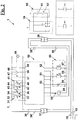
- a safety apparatus 1 is described to preserve the users' safety in a swimming pool 10 equipped with at least one withdrawal mouth 11 and at least one return mouth 19.
- the withdrawal mouths can be located at the bottom of pool 10, like depicted mouth 19, or substantially at the normal level 12 of water 13, in the latter case in order to remove material floating on water 13 (skimmer).
- only one withdrawal mouth 19 located on the bottom is shown, which can also serve as a drainage, i.e. it can be used to empty the pool.
- a purification circuit 20 is associated to swimming pool 10, including a conventional purification plant 27, through which water 13 of swimming pool 10 is caused to flow continuously at a predetermined flowrate.
- Purification circuit 20 comprises a circulation pump 25, a suction piping schematically represented as a suction duct or branch 21, a delivery duct 28 and a delivery piping 29 to supply purified water to the possible multiple return mouths 19 of swimming pool 10.
- Circulation pump 25 is powered through a power supply line 40, including a fuse 39, and a contactor 24 enabling a remote control of the pump.
- circulation pump 25 is a centrifugal pump, but in some exemplary embodiments it can be a positive displacement pump.
- safety apparatus 1 shown in a box of Fig. 1 , comprises at least two pressure switches 31,41 that are electrically connected to a power supply line 30 advantageously including a fuse 39', which is preferably a DC power supply line at a suitable voltage, e.g. 24V or 12V, said pressure switches in use hydraulically connected to suction duct 21 of purification circuit 20.
- DC power supply line 30 can be connected to main power supply line 40 via a transformer 37.
- Pressure switches 31,41 can be conventional pressure switches, for example provided by SMC company, and the parts of them that are in contact with water are advantageously selected so as to chemically resist to the oxidant agents normally used to treat the swimming pool water, such as chloride, oxygen, ozone, or various salts.
- Apparatus 1 also comprises a logic unit 50 electrically connected to pressure switches 31,41 and to warning devices that can be parts of apparatus 1 or external devices, as described more in detail hereinafter.
- Logic unit 50 preferably includes a microcontroller, for example it can include a Siemens "LOGO! PLC, or can be a microprocessor logic unit, but it can also be a fully electromechanical logic unit.
- two pressure switches 31 and 41 are connected to a same pressure-detection point 22, preferably through a same tube 26, which can be made of Rilsan or a similar material, comprising tubes 26' and 26" for two pressure switches 31 and 41.
- two pressure switches 31 and 41 can be connected to suction duct 21 trough distinct tubes, substantially in the same pressure-detection point 22 i.e. in points that are so close to each other that the pressure difference between these detection points is lower than an given amount, preferably lower than the resolution of pressure switches 31 and 41, so as to read substantially the same suction pressure P.
- Pressure switches 31,41 are configured to detect negative relative pressures, within a range including vacuum degree values that can be obtained as the suction pressure by pump 25 having a given characteristic curve, and that can be determined from the prefixed circulation flowrate in circuit 20, the features of duct 21 and the distance between the pressure-detection point 22 and the suction side of pump 25.
- Each pressure switch 31,41 at least comprises a respective first contact 33,43 and a respective second contact 34,44.
- Each pressure switch 31,41 is configured to be calibrated in such a way that first contacts 33,43 change their own state, by preferably opening, but possibly by closing, when pressure P at the pressure-detection point drops below an emergency stop pressure P a , predetermined responsive to an abnormal vacuum value that is expected if withdrawal mouth 11 is even partially blocked. This can occur when a user who is close to withdrawal mouth 11 is sucked by pump 25 and retained on withdrawal mouth 11, or trapped within it.
- first contacts 33,43 change their own status in the opposite way with respect to before.
- first contacts 33,43 of pressure switches 31,41 are normally-closed contacts.
- a suitable value of relative emergency stop pressure P a for the calibration can be set between -0.3 and -0.6 bar, in particular between -0.4 and -0.5 bar, typically this value can be set at about -0,45 bar.
- Emergency stop pressure P a can be selected taking into account that other withdrawal mouths are present that, like withdrawal mouth 11, are hydraulically connected to the suction branch or duct 21, and by performing suction tests when installing safety apparatus 1 in a specific circuit 20 of a specific pool 10.
- each pressure switch 31,41 is configured to be calibrated in such a way that seconds contacts 34,44 change their own state, opening or closing, when pressure P at the pressure-detection point drops below a maximum operation pressure P e , i.e. when the vacuum degree at the pressure-detection point 22 reaches an expected operation value. Even in this case, if pressure P becomes higher than maximum operation pressure P e again, seconds contacts 34,44 change their own status in in the opposite direction.
- seconds contacts 34,44 of pressure switches 31,41 are normally-open contacts.
- apparatus 1 also includes a warning device 65, which can comprise a device selected among an acoustic warning device 66-67, a visual warning device 68, or a combination of visual and acoustic devices.
- the acoustic warning device can include one or more units 66,67 like conventional hooters that are connected to respective outputs 51,52 of logic unit 50.
- visual warning device 68 can comprise a conventional blinker, and is connected to an output 53 of logic unit 50.
- a power supply line 30' which is preferably a DC supply line and advantageously incudes a fuse 39" can be derived from main power supply line 40 through a transformer 38 to power, inter alia, the components of warning device 65.
- warning device 65 includes both visual 68 and acoustic 66,67 warning devices.
- Logic unit 50 is preferably configured to operate warning device 65, preferably both acoustic devices 66,67 and visual devices 68, when at least one of first contacts 33,43 changes its own status into the status corresponding to the alarm emergency condition, in which P ⁇ P a .
- logic unit 50 is preferably configured to operate warning device 65, preferably both acoustic devices 66,67 and visual device 68, when the statuses of second contacts 34,44 indicate pressure P values different from each other and at opposite sides of maximum operation pressure P e , i.e. when one of these status indicates that suction pressure P ⁇ P e , while the other status indicates that suction pressure P>P e .
- Logic unit 50 is preferably configured to cause acoustic warning device 66-67 to emit different tones for the alarm emergency condition, in which P ⁇ P a , and for the instrument-inconsistency condition, in which [P ⁇ P e and P>P e ].
- the tone can be high and continuous, while in the latter case the tone can be lower and preferably intermittent.
- the tone can be high and continuous if the alarm emergency condition P ⁇ P a is generated by both pressure switches 31 and 41, and lower and preferably intermittent if the alarm emergency condition P ⁇ P a is generated by only one of pressure switches 31 and 41, and also if an instrument-inconsistency condition occurs.
- logic unit 50 is preferably configured to operate visual device 68 in a different ways according to whether an alarm emergency condition occurs, in which P ⁇ P a , or an instrument-inconsistency condition occurs, in which the statuses of first contacts 33,43 indicate pressure P values different from each other, and at opposite sides with respect to maximum operation pressure P e , i.e. when one of them indicates that suction pressure P ⁇ P e , while the other indicates that suction pressure P>P e , for instance blinkers or lights of different colours can be actuated, provided obviously that pump 25 is prevented from running in that condition.
- a further different tone can even be emitted if the expected operating conditions are nor reached within a predetermined time since when a pump-start command for pump 25 has been received, i.e., if the condition P>P e is still present after this predetermined time.
- a signalling corresponding to a pressure value P higher than maximum operation pressure P e during the operation of pump 25 provides an additional indication, unrelated with the users' safety function, of a possible hydraulic fault of circuit 20, typically of a possible fault of pump 25.
- a value of maximum operation pressure P e can be set between -0.1 and -0.3 bar, in particular between -0.15 and -0.25 bar, typically this value can be close to -0.19 bar.
- the selected value can be based on a hydraulic calculation and/or established when testing the plant at the design water flowrate of the purification plant 27.
- the flowrate of purification circuit 20 can be set by conventional control devices, not shown, such as a control valve or an orifice having a predetermined diameter arranged along purification circuit 20, or by an inverter device arranged to controlling the RPM of pump 25.
- control devices not shown, such as a control valve or an orifice having a predetermined diameter arranged along purification circuit 20, or by an inverter device arranged to controlling the RPM of pump 25.
- the characteristic curve of pump 25 can be selected such that the pump, in a specific operation mode, can quickly empty the pool.
- the pull 10 empty mode can be selected by acting on the above-mentioned control means or by bypassing them.
- Logic unit 50 has two inputs 32 and 42 electrically connected to the first contacts of pressure switch 31 and of pressure switch 41, respectively, so as to detect the open status, if contact 33,43 are normally closed, or the closed status, if they are normally open.
- the statuses of contacts 33,43 indicate with redundancy whether suction pressure P in suction branch 21 has exceeded or has dropped below emergency stop pressure P a .
- logic unit 50 has two other inputs 36 and 46 electrically connected to the seconds contacts of pressure switch 31 and of pressure switch 41, respectively, so as to detect the open or closed status, if contact 34,44 are normally closed or normally-open contacts, respectively.
- the statuses of contacts 34,44 indicate with redundancy whether the pressure in suction branch 21 has dropped below or has exceeded the maximum working pressure P e , corresponding to the minimum vacuum degree, i.e. they indicate whether the stationary conditions of purification circuit 20 have been reached.
- logic unit 50 is also electrically connected to contactor 24, arranged to power pump 25, so as to open or close the contactor according to a program provided in a microprocessor, of by a plurality of contacts of the logic unit.
- logic unit 50 is configured to generate and transfer a pump stop/block electric signal 55 to contactor 24 when it detects the open or closed status of at least one of first contacts 33,43, according to whether this is a normally-closed contact -which is preferable-, or a normally-open contact.
- Contactor 24 is configured to block the power supply to circulation pump 25 upon receiving pump stop/block electric signal 55.
- safety apparatus 1 In which the status of the pump depends on the status of first contacts 33,43 of pressure switches 31,41, have been described above.
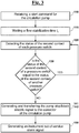
- logic unit 50 is typically configured to carry out a step 110 of receiving a pump-start command for circulation pump 25 and, according to the invention, it is also configured to carry out sequentially the subsequent steps indicated below, in order to control the apparatus, as described hereinafter.
- logic unit 50 carries out a step 130 of comparing the statuses of second contacts 34,44 of two pressure switches 31,41 with each other. If in one of detection and comparison cycles 120-130 an instrument-inconsistency condition is encountered, i.e.
- logic unit 50 performs steps of generating 141 and transferring 142 pump stop/block electric signal 55 to contactor 24 of pump 25, so that contactor 24 breaks or prevents any power supply to pump 25. Still in the instrument-inconsistency condition, logic unit 50 is also configured to carry out a step 150 of generating an instrument out-of-service alarm signal.
- logic unit 50 is typically configured to carry out a step 110 of receiving of a pump-start command for circulation pump 25 and, according to the invention, it is also configured to sequentially carry out the apparatus control steps described hereinafter.
- logic unit 50 carries out a step 131 of verifying the statuses of first contacts 33,43 of two pressure switches 31,41. If in one of detection and verification cycles 120-131 a condition is detected in which first contacts 33,43 are in a logic status according to which the pressure is higher than emergency stop pressure, in particular if first contacts 33,43 are normally closed -which is preferred -, when this logic status is 0 V, logic unit 50 performs steps of generating 141 and transferring 142 pump stop/block electric signal 55 to contactor 24 of pump 25, in such a way that contactor 24 breaks or prevents any power supply to pump 25.
- logic unit 50 is also configured to carry out a step 145 of generating an emergency alarm signal, so as to actuate emergency warning devices 66,68, as described hereinafter.
- a block condition can be withdrawn with a reset command, the logic unit being configured for a step 148 of receiving it. If no such a command is received, pump-block status and the emergency alarm continue, while, in the opposite case, the running of circulation pump 25 is enabled again, upon receiving 110 a command therefor.
- logic unit 50 carries out a step 135 of checking the presence of an instrument-inconsistency condition, wherein - in the preferred cases in which first contacts 33,43 are normally closed and seconds contacts 34,44 are normally open - only one of said contacts has the logic status 0 V, logic unit 50 is configured to carry out steps 141, 142 of generating and transferring pump stop/block electric signal 55, and step 150 of generating an instrument out-of-service alarm signal, as already described with reference to Fig. 3 .
- logic unit 50 after receiving the pump-start command for circulation pump 25 in the reception step 110, logic unit 50 is configured to carry out a step 115 of waiting a flow-stabilization time t s previously set inside it, before detecting and cyclically processing the statuses of contacts 33,43 and 34,44 of pressure switches 31,41 in the steps 120-130 and 120-135-136, in order to avoid a permanent block condition of pump 25.
- the vacuum degree in suction duct 21 can reach and exceed for a short time the vacuum degree corresponding to emergency stop pressure P a .
- the object of the step of waiting is to neglect this transitory condition.
- the step 115 of waiting is shown by a dashed line because it is an optional step.
- apparatus 1 can comprise an unblock key device 60, i.e. a device for manually removing the block condition generated by the instrument-inconsistency condition, in other words a key device can be provided to enable manually switching the pump on even if an instrument inconsistency or fault conditions is present.
- unlock device 60 comprises a switch or switch unit whose status can be modified preferably by introducing a confidential code into the logic unit, i.e. a code that is not shown on the device. This code can be confidentially entrusted to the swimming pool manager or to a delegated person.
- key device 60 is configured to generate a signal for enabling the pump to be operated if an instrument fault condition is present, and logic unit 50 is configured to receive this signal and to generate a condition for enabling a pump operation even in the presence of an instrument fault condition, in which the step of generating pump stop/block electric signal 55 is inhibited.
- key device 60 is a multiple key device, in which multiple switches 61,62 are provided, the status of which can be modified with respective keys that are different from one another.
- key device 60 is a mechanical key unit, in other words the apparatus comprises at least one switch 61,62 accessible and/or configured to be switched by means of a conventional mechanical key that is entrusted to the manager or to a person delegated by him/her.
- key device 60 can in any case comprise an alphanumerical key unit, in other words, apparatus 20 can comprise a keyboard or an equivalent means for introducing a confidential alphanumerical code.
- logic unit 50 is configured to carry out a step 160 of receiving a command of temporary inhibition of pump stop/block electric signal 55 and, upon receiving this command, to carry out also a step 170 of generating an emergency-stop temporary inhibition condition and a step 165 of starting a timer t that measures the duration of that condition until a predetermined inhibition time ti has elapsed.
- step 160 of receiving a command of temporary inhibition of pump stop/block electric signal 55 and, upon receiving this command, to carry out also a step 170 of generating an emergency-stop temporary inhibition condition and a step 165 of starting a timer t that measures the duration of that condition until a predetermined inhibition time ti has elapsed.
- inhibition time ti can be set by a conventional timer 49, which operates a contact 59 that is maintained closed during the predetermined inhibition time ti, and that is opened again upon elapsing of inhibition time ti.
- inhibition time ti can be set to 15 minutes, or in any case it can be as long as the time required for completely or partially emptying pool 10 and/or performing a maintenance operation that requires that pump 25 delivers its maximum flowrate, in order to empty the pool at an acceptable speed, even if a vacuum degree is created in duct 21 higher than the emergency alarm value, corresponding to emergency stop pressure P a .
- Elapsing of inhibition time ti triggers a step 190 of removing the emergency-stop temporary inhibition condition, and then apparatus 1 is enabled again to stop circulation pump 25 by pump stop/block electric signal 55, if the pressure in the suction duct drops below P a .
- logic unit 50 can be configured to perform a step 180 of generating an emergency-stop temporary inhibition alarm signal, which can be used for operating warning device 65, in order to notify the condition of high suction vacuum safety inhibition during inhibition time ti, which can be prolonged by an extension time t p , as described hereinafter.
- an emergency-stop temporary inhibition alarm signal which can be used for operating warning device 65, in order to notify the condition of high suction vacuum safety inhibition during inhibition time ti, which can be prolonged by an extension time t p , as described hereinafter.
- the same contact 47 can be used that is connected to an input 57 of logic unit 50.
- logic unit 50 can be configured to perform:
- logic unit 50 can be configured to carry out a step 189 of emitting a signal of forthcoming end of the emergency-stop temporary inhibition condition a forthcoming safety reactivation time tir before the inhibition time ti elapses.
- This signal can operate a second acoustic alarm or hooter through output 52 of logic unit 50, for example by emitting an intermittent tone.
- steps 180, 189 and the sequences of steps 181-182, 186-187 are shown with dashed lines, since they are distinct modifications, which can also be combined to one another, of an exemplary embodiment providing the sequence of steps 160-165-170-190, i.e. the condition of inhibition on demand of the emergency stop of the pump during a predetermined inhibition time.
- steps 160-165-170-190 i.e. the condition of inhibition on demand of the emergency stop of the pump during a predetermined inhibition time.
- pressure sensors/transmitters can be used that have switch thresholds corresponding to emergency alarm pressures P a and to maximum operation pressure P e , and that are arranged to detect pressure values in a continuous pressure range including the values P a and P e and, preferably, other values that are important to understand various operating conditions of pump 25 and of purification circuit 20.
- input peripheral devices pressure switches, pressure sensors/transmitters, push-buttons, timers etc.
- output peripheral devices visual and acoustic warning devices, etc.
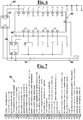
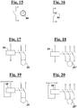
- Figs. 6-20 show detailed wiring diagrams of a safety apparatus according to a preferred exemplary embodiment of the invention.
- Fig. 6 shows the logic unit or drive control unit 50 providing 24V direct voltage inputs, indicated as +, -, I1, I2, I3, I4, I5, I6, I7, I8 and outputs, Q1, Q2, Q3, Q4.
- Fig. 7 shows a terminal board 70 that is preferably arranged in the same main electrical cabinet where logic unit 50 is housed, the terminal board providing a plurality of terminals 71-100 for connecting logic unit 50 with the inlet and output peripherals and, in some instances, for connecting the peripherals with each other.
- Fig. 7 also indicates the function of each terminal 71-100.
- FIG. 6 two voltage transformers, or power supply units 37, 38, are also shown arranged to be supplied at a 230V AC voltage by power supply line 40 and connected to terminals 71, 72 corresponding to the phase L and to the neutral N, and configured to change said voltage into a 24 V DC voltage.
- a first transformer 37 is arranged to supply logic unit 50 and the input peripherals (pressure switches, command push-buttons, the timer), while a second transformer 38 is arranged to supply the output peripherals (acoustic/visual warning devices, the relay of the circulation pump) of the apparatus, as described hereinafter.
- a terminal 73 allows the ground connection of control unit 50.
- pressure switches 31 and 41 and logic unit or control unit 50 are electrically supplied through terminals 74, 75.
- First contacts 33,43, in this case normally-closed contacts, of pressure switches 31 and 41 are connected between 24V terminal 74 and inputs 76 and 77, respectively.
- a lack of 24V voltage at terminals 76 and 77 indicates to control unit 50 that pressure switches 31 and 41 have detected a pressure that is the same value as or lower than emergency stop pressure P a , respectively.
- logic unit 50 acts on a relay R of circulation pump 25 through an own output Q1 ( Fig. 6 ), by a pump-stop/block signal, preventing the pump from running.
- logic unit 50 through output Q3 connected to a terminal 85, allows supplying the 24V voltage to acoustic and visual emergency warning devices 66 and 68, which are connected in parallel between terminals 85 and 86 (0 V), and are arranged to notify people who are in the neighbourhood of the swimming pool of a condition of excessive vacuum degree and probable entrapment of someone upstream of the circulation pump.
- acoustic warning device 66 can be a hooter
- emergency visual warning device 68 can be a red high-intensity blinker.
- logic unit 50 operates general acoustic and visual emergency warning devices 66 and 68 through output Q3 only if both pressure switches 31 and 41 indicate the condition P ⁇ P a , i.e. if the 24 V voltage is not present at any of contacts 76, 77, without prejudice of the block of the circulation pump even if one only of the pressure switch indicates the condition P ⁇ P a , i.e. if one only of contacts 76, 77 does not receive the 24 V voltage.
- second contacts 34,44 in this case normally-open contacts, of pressure switches 31 and 41, are connected between 24V terminal 74 and inputs 78 and 79, respectively.
- logic unit 50 through output Q2 connected to terminal 87, allows feeding the 24V voltage only to a visual fault warning device 69, connected between terminals 87 and 86 (0 V), and arranged at the electrical cabinet, in order to notify an instrument fault condition to an operator, which requires to be checked and possibly fixed.
- Visual fault warning device 69 can be a light of a different colour and lower intensity than above-mentioned blinker 68, for example, it can be a yellow light.
- logic unit 50 still through output Q1 ( Fig. 6 ), also acts even in this case on relay R of circulation pump 25, preventing the latter from running.
- logic unit 50 similarly acts on visual fault warning device 69 and on relay R of the pump, responsive not only to the voltage values at inputs I3 and 14, but also to the voltage values at inputs I1 and 12, which are connected to terminals 76 and 77, i.e. to the first contacts of two pressure switches 31 and 41, respectively.
- first contacts 33,43 are normally closed and seconds contacts 34,44 are normally open
- the 24 V voltage is expected to be present at all four inputs I1, I2, I3, I4.
- logic unit 50 also in this case acts on relay R of circulation pump 25, preventing the latter from running and, through output Q2, allows supplying the 24V voltage only to visual fault warning device 69, in order to notify the instrument fault condition to an operator, which requires to be checked and possibly fixed.
- This condition can be an instrument fault, such as a fault of the power supply coil of a pressure switch, or a cut wire, which prevents the 24 V signal from reaching logic unit 50.
- Fig. 9 shows a portion of the electrical cabinet that controls the condition of temporary inhibition of the pump-stop/block electric signal, in particular, during a maintenance operation.
- a terminal 80 carrying a 24V voltage generated by transformer 37, and terminals 82, 83 connected to inputs I5 and I6, respectively, of the control unit two normally closed push-buttons 47 are arranged to reactivate the apparatus after a temporary inhibition condition, as well as a push-button 48 for temporary inhibiting pump stop/block electric signal 55 i.e. for setting a maintenance time. Therefore, only in the presence of 24V voltage at terminal 81 and, therefore, at input 15, logic unit 50 enables the operation of the apparatus.
- input I6 receives the 24V voltage, and in this case logic unit 50 activates the temporary inhibition condition of the pump-stop/block electric signal, during a predetermined inhibition time, even if a pressure P ⁇ P a is detected.
- logic unit 50 when the end of the inhibition time approaches, logic unit 50, through output Q4 connected to terminal 83, can allow the 24V voltage to be supplied to maintenance acoustic warning device 67, connected between terminals 87 and 86 (0 V), and arranged to notify a maintenance operator of the condition of forthcoming end of the maintenance time.
- maintenance acoustic warning device 67 is caused to emit an intermittent signal with a frequency that gradually increases as the end of the inhibition time approaches.
- logic unit 50 can be configured also to activate visual fault warning device 69, as indicated above when describing Fig. 8 .
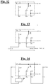
- FIGs. 17 and 18 show 24V contactor 24 for a circulation pump having a single-phase electric motor 25' (the phase and neutral are indicated by L and N) and for a circulation pump having a three-phase electric motor 25" (the three phases are indicated by L1, L2, L3), respectively, each motor connected between a terminal 92 (0 V) and a terminal 93 in turn connected to common contact C of relay R, which can be selectively supplied at 24V, as it can be seen in Figs. 12-14 .
- 2 terminals 99 and 100 are arranged that can be connected to respective terminals of an emergency button 54 that has a normally-closed contact and is shown in Fig. 16 , which button can be operated in any condition to prevent a 24V voltage from reaching terminal 93 and, therefore, to prevent the circulation pump from running.
- a terminal 96 carrying a 24V voltage generated by transformer 38 is connected through a terminal 95 to normally-open contact NO of relay R.
- the pump stop/block signal emitted by control unit 50 if a high vacuum degree is attained, P ⁇ Pa, or if one of two pressure switches 31 and 41 indicates that P>P e while the other indicates that P ⁇ P e , switches the relay bringing the common contact C from contact NO to contact NC thus preventing the 24V voltage from reaching terminal 93 and the contactor of pump 25, and preventing therefore the pump from running.
- a double-key device 60 can be arranged comprising two normally-open contacts in series which can be closed, for example, acting at the same time on first key 61 and on second key 62, thus bypassing the relay and bringing the 24V voltage to common contact, i.e. to terminal 93, in any condition, so as to enable pump 25 to run regardless of the status of relay R, i.e. regardless of whether pump stop/block signal 55 has been emitted by control unit 50 in the case P ⁇ P a .
- Double-key device 60 increases the surveillance on whether the apparatus is reactivated and on whether pump 25 is switched on again after a general alarm general, for instance, by confidentially consigning the first and the second key to two different subjects that shares this responsibility, while making it easier to silence acoustic/visive warning devices 66,68, so as to reduce the inconvenience they cause to the operators.
- terminals 97, 98 are also shown connected to input I8 of the control unit, and to 24V supply unit 37, respectively, in order to connect timer 49, for example a timer 49 previously in use, for measuring the time during which circulation pump 25 is running.
Landscapes
- Engineering & Computer Science (AREA)
- Architecture (AREA)
- Civil Engineering (AREA)
- Structural Engineering (AREA)
- Mechanical Engineering (AREA)
- General Engineering & Computer Science (AREA)
- Control Of Positive-Displacement Pumps (AREA)
- Fluid-Pressure Circuits (AREA)
- Percussion Or Vibration Massage (AREA)
- Control Of Non-Positive-Displacement Pumps (AREA)
Applications Claiming Priority (1)
| Application Number | Priority Date | Filing Date | Title |
|---|---|---|---|
| IT102018000021448A IT201800021448A1 (it) | 2018-12-28 | 2018-12-28 | Apparato e metodo per lesercizio sicuro di piscine |
Publications (2)
| Publication Number | Publication Date |
|---|---|
| EP3674500A1 EP3674500A1 (en) | 2020-07-01 |
| EP3674500B1 true EP3674500B1 (en) | 2021-11-03 |
Family
ID=66166321
Family Applications (1)
| Application Number | Title | Priority Date | Filing Date |
|---|---|---|---|
| EP19219945.3A Active EP3674500B1 (en) | 2018-12-28 | 2019-12-28 | A safety apparatus for a swimming pool |
Country Status (6)
| Country | Link |
|---|---|
| EP (1) | EP3674500B1 (da) |
| CY (1) | CY1124895T1 (da) |
| DK (1) | DK3674500T3 (da) |
| ES (1) | ES2904498T3 (da) |
| IT (1) | IT201800021448A1 (da) |
| PT (1) | PT3674500T (da) |
Families Citing this family (1)
| Publication number | Priority date | Publication date | Assignee | Title |
|---|---|---|---|---|
| CN118724113B (zh) * | 2024-08-06 | 2025-11-25 | 珠海格力电器股份有限公司 | 净水设备制水控制方法、装置、净水设备及存储介质 |
Family Cites Families (4)
| Publication number | Priority date | Publication date | Assignee | Title |
|---|---|---|---|---|
| US6059536A (en) | 1996-01-22 | 2000-05-09 | O.I.A. Llc | Emergency shutdown system for a water-circulating pump |
| US5690476A (en) * | 1996-10-25 | 1997-11-25 | Miller; Bernard J. | Safety device for avoiding entrapment at a water reservoir drain |
| US5865601A (en) * | 1998-02-06 | 1999-02-02 | Miller; Bernard J. | Safety device for avoiding entrapment at a water reservoir drain having a secondary blowing pump |
| JP2001073576A (ja) * | 1999-09-06 | 2001-03-21 | Nichigi Engineering Co Ltd | プールの排水口における危険防止システム |
-
2018
- 2018-12-28 IT IT102018000021448A patent/IT201800021448A1/it unknown
-
2019
- 2019-12-28 PT PT192199453T patent/PT3674500T/pt unknown
- 2019-12-28 ES ES19219945T patent/ES2904498T3/es active Active
- 2019-12-28 EP EP19219945.3A patent/EP3674500B1/en active Active
- 2019-12-28 DK DK19219945.3T patent/DK3674500T3/da active
-
2022
- 2022-01-05 CY CY20221100016T patent/CY1124895T1/el unknown
Also Published As
| Publication number | Publication date |
|---|---|
| IT201800021448A1 (it) | 2020-06-28 |
| ES2904498T3 (es) | 2022-04-05 |
| PT3674500T (pt) | 2022-01-11 |
| EP3674500A1 (en) | 2020-07-01 |
| CY1124895T1 (el) | 2023-01-05 |
| DK3674500T3 (da) | 2022-01-10 |
Similar Documents
| Publication | Publication Date | Title |
|---|---|---|
| US5947700A (en) | Fluid vacuum safety device for fluid transfer systems in swimming pools | |
| US6171073B1 (en) | Fluid vacuum safety device for fluid transfer and circulation systems | |
| US6059536A (en) | Emergency shutdown system for a water-circulating pump | |
| US4896144A (en) | Hand washing alert | |
| US20010002238A1 (en) | Vacuum relief device for fluid transfer and circulation systems | |
| JP2008525163A (ja) | 脱イオンおよび電気化学的浄化用の関連構成要素および装置および電極の再生方法 | |
| US7030767B2 (en) | Water leak mitigation system | |
| US12122638B2 (en) | Vertical platform lift and control system | |
| CN108439117B (zh) | 电梯松闸装置 | |
| EP3674500B1 (en) | A safety apparatus for a swimming pool | |
| US20210078824A1 (en) | Vertical platform lift and control system | |
| US6323777B1 (en) | Timer with resettable alarm and automatic turn-off | |
| CN203520597U (zh) | 一种电动阀门防漏水报警装置 | |
| JPH01178289A (ja) | 洗濯機の保護装置 | |
| CN112587702A (zh) | 一种电梯轿厢杀菌消毒控制系统及其控制方法 | |
| JPH09159714A (ja) | アース線接続確認装置 | |
| JPH0254991B2 (da) | ||
| GB1257729A (da) | ||
| CN218493768U (zh) | 砂滤器及其控制系统 | |
| JPS61239761A (ja) | 遠距離監視装置 | |
| CN112526863A (zh) | 智能公厕的厕位使用监管系统 | |
| KR102336595B1 (ko) | 자동 역세 기능 및 염소투입기 이상 알람 기능을 갖춘 스마트 잔류염소측정장치 | |
| CN212966499U (zh) | 一种安全监测系统 | |
| CN109597341B (zh) | 一种工程机械辅助功能安全启动控制装置及方法 | |
| KR101415938B1 (ko) | 수족관용 무정전 에어공급시스템 |
Legal Events
| Date | Code | Title | Description |
|---|---|---|---|
| PUAI | Public reference made under article 153(3) epc to a published international application that has entered the european phase |
Free format text: ORIGINAL CODE: 0009012 |
|
| STAA | Information on the status of an ep patent application or granted ep patent |
Free format text: STATUS: THE APPLICATION HAS BEEN PUBLISHED |
|
| AK | Designated contracting states |
Kind code of ref document: A1 Designated state(s): AL AT BE BG CH CY CZ DE DK EE ES FI FR GB GR HR HU IE IS IT LI LT LU LV MC MK MT NL NO PL PT RO RS SE SI SK SM TR |
|
| AX | Request for extension of the european patent |
Extension state: BA ME |
|
| STAA | Information on the status of an ep patent application or granted ep patent |
Free format text: STATUS: REQUEST FOR EXAMINATION WAS MADE |
|
| 17P | Request for examination filed |
Effective date: 20201229 |
|
| RBV | Designated contracting states (corrected) |
Designated state(s): AL AT BE BG CH CY CZ DE DK EE ES FI FR GB GR HR HU IE IS IT LI LT LU LV MC MK MT NL NO PL PT RO RS SE SI SK SM TR |
|
| GRAP | Despatch of communication of intention to grant a patent |
Free format text: ORIGINAL CODE: EPIDOSNIGR1 |
|
| STAA | Information on the status of an ep patent application or granted ep patent |
Free format text: STATUS: GRANT OF PATENT IS INTENDED |
|
| INTG | Intention to grant announced |
Effective date: 20210517 |
|
| RIC1 | Information provided on ipc code assigned before grant |
Ipc: E04H 4/06 20060101AFI20210430BHEP Ipc: A61H 33/00 20060101ALI20210430BHEP Ipc: F04B 49/10 20060101ALI20210430BHEP |
|
| RAP1 | Party data changed (applicant data changed or rights of an application transferred) |
Owner name: RONTANI, FLAVIO |
|
| RIN1 | Information on inventor provided before grant (corrected) |
Inventor name: LAZZARINI, MASSIMILIANO Inventor name: RONTANI, FLAVIO |
|
| GRAS | Grant fee paid |
Free format text: ORIGINAL CODE: EPIDOSNIGR3 |
|
| GRAA | (expected) grant |
Free format text: ORIGINAL CODE: 0009210 |
|
| STAA | Information on the status of an ep patent application or granted ep patent |
Free format text: STATUS: THE PATENT HAS BEEN GRANTED |
|
| RAP1 | Party data changed (applicant data changed or rights of an application transferred) |
Owner name: A.W.S. TECHNOLOGIES SRL |
|
| AK | Designated contracting states |
Kind code of ref document: B1 Designated state(s): AL AT BE BG CH CY CZ DE DK EE ES FI FR GB GR HR HU IE IS IT LI LT LU LV MC MK MT NL NO PL PT RO RS SE SI SK SM TR |
|
| REG | Reference to a national code |
Ref country code: GB Ref legal event code: FG4D |
|
| REG | Reference to a national code |
Ref country code: AT Ref legal event code: REF Ref document number: 1444082 Country of ref document: AT Kind code of ref document: T Effective date: 20211115 Ref country code: CH Ref legal event code: EP |
|
| REG | Reference to a national code |
Ref country code: IE Ref legal event code: FG4D |
|
| REG | Reference to a national code |
Ref country code: DE Ref legal event code: R096 Ref document number: 602019008957 Country of ref document: DE |
|
| REG | Reference to a national code |
Ref country code: DK Ref legal event code: T3 Effective date: 20220107 |
|
| REG | Reference to a national code |
Ref country code: PT Ref legal event code: SC4A Ref document number: 3674500 Country of ref document: PT Date of ref document: 20220111 Kind code of ref document: T Free format text: AVAILABILITY OF NATIONAL TRANSLATION Effective date: 20220104 |
|
| REG | Reference to a national code |
Ref country code: NL Ref legal event code: FP |
|
| REG | Reference to a national code |
Ref country code: LT Ref legal event code: MG9D |
|
| REG | Reference to a national code |
Ref country code: GR Ref legal event code: EP Ref document number: 20220400019 Country of ref document: GR Effective date: 20220211 |
|
| REG | Reference to a national code |
Ref country code: AT Ref legal event code: MK05 Ref document number: 1444082 Country of ref document: AT Kind code of ref document: T Effective date: 20211103 |
|
| REG | Reference to a national code |
Ref country code: ES Ref legal event code: FG2A Ref document number: 2904498 Country of ref document: ES Kind code of ref document: T3 Effective date: 20220405 |
|
| PG25 | Lapsed in a contracting state [announced via postgrant information from national office to epo] |
Ref country code: RS Free format text: LAPSE BECAUSE OF FAILURE TO SUBMIT A TRANSLATION OF THE DESCRIPTION OR TO PAY THE FEE WITHIN THE PRESCRIBED TIME-LIMIT Effective date: 20211103 Ref country code: LT Free format text: LAPSE BECAUSE OF FAILURE TO SUBMIT A TRANSLATION OF THE DESCRIPTION OR TO PAY THE FEE WITHIN THE PRESCRIBED TIME-LIMIT Effective date: 20211103 Ref country code: FI Free format text: LAPSE BECAUSE OF FAILURE TO SUBMIT A TRANSLATION OF THE DESCRIPTION OR TO PAY THE FEE WITHIN THE PRESCRIBED TIME-LIMIT Effective date: 20211103 Ref country code: BG Free format text: LAPSE BECAUSE OF FAILURE TO SUBMIT A TRANSLATION OF THE DESCRIPTION OR TO PAY THE FEE WITHIN THE PRESCRIBED TIME-LIMIT Effective date: 20220203 Ref country code: AT Free format text: LAPSE BECAUSE OF FAILURE TO SUBMIT A TRANSLATION OF THE DESCRIPTION OR TO PAY THE FEE WITHIN THE PRESCRIBED TIME-LIMIT Effective date: 20211103 |
|
| PG25 | Lapsed in a contracting state [announced via postgrant information from national office to epo] |
Ref country code: IS Free format text: LAPSE BECAUSE OF FAILURE TO SUBMIT A TRANSLATION OF THE DESCRIPTION OR TO PAY THE FEE WITHIN THE PRESCRIBED TIME-LIMIT Effective date: 20220303 Ref country code: SE Free format text: LAPSE BECAUSE OF FAILURE TO SUBMIT A TRANSLATION OF THE DESCRIPTION OR TO PAY THE FEE WITHIN THE PRESCRIBED TIME-LIMIT Effective date: 20211103 Ref country code: PL Free format text: LAPSE BECAUSE OF FAILURE TO SUBMIT A TRANSLATION OF THE DESCRIPTION OR TO PAY THE FEE WITHIN THE PRESCRIBED TIME-LIMIT Effective date: 20211103 Ref country code: NO Free format text: LAPSE BECAUSE OF FAILURE TO SUBMIT A TRANSLATION OF THE DESCRIPTION OR TO PAY THE FEE WITHIN THE PRESCRIBED TIME-LIMIT Effective date: 20220203 Ref country code: LV Free format text: LAPSE BECAUSE OF FAILURE TO SUBMIT A TRANSLATION OF THE DESCRIPTION OR TO PAY THE FEE WITHIN THE PRESCRIBED TIME-LIMIT Effective date: 20211103 Ref country code: HR Free format text: LAPSE BECAUSE OF FAILURE TO SUBMIT A TRANSLATION OF THE DESCRIPTION OR TO PAY THE FEE WITHIN THE PRESCRIBED TIME-LIMIT Effective date: 20211103 |
|
| PG25 | Lapsed in a contracting state [announced via postgrant information from national office to epo] |
Ref country code: SM Free format text: LAPSE BECAUSE OF FAILURE TO SUBMIT A TRANSLATION OF THE DESCRIPTION OR TO PAY THE FEE WITHIN THE PRESCRIBED TIME-LIMIT Effective date: 20211103 Ref country code: SK Free format text: LAPSE BECAUSE OF FAILURE TO SUBMIT A TRANSLATION OF THE DESCRIPTION OR TO PAY THE FEE WITHIN THE PRESCRIBED TIME-LIMIT Effective date: 20211103 Ref country code: RO Free format text: LAPSE BECAUSE OF FAILURE TO SUBMIT A TRANSLATION OF THE DESCRIPTION OR TO PAY THE FEE WITHIN THE PRESCRIBED TIME-LIMIT Effective date: 20211103 Ref country code: EE Free format text: LAPSE BECAUSE OF FAILURE TO SUBMIT A TRANSLATION OF THE DESCRIPTION OR TO PAY THE FEE WITHIN THE PRESCRIBED TIME-LIMIT Effective date: 20211103 Ref country code: CZ Free format text: LAPSE BECAUSE OF FAILURE TO SUBMIT A TRANSLATION OF THE DESCRIPTION OR TO PAY THE FEE WITHIN THE PRESCRIBED TIME-LIMIT Effective date: 20211103 |
|
| REG | Reference to a national code |
Ref country code: DE Ref legal event code: R097 Ref document number: 602019008957 Country of ref document: DE |
|
| PG25 | Lapsed in a contracting state [announced via postgrant information from national office to epo] |
Ref country code: MC Free format text: LAPSE BECAUSE OF FAILURE TO SUBMIT A TRANSLATION OF THE DESCRIPTION OR TO PAY THE FEE WITHIN THE PRESCRIBED TIME-LIMIT Effective date: 20211103 |
|
| PLBE | No opposition filed within time limit |
Free format text: ORIGINAL CODE: 0009261 |
|
| STAA | Information on the status of an ep patent application or granted ep patent |
Free format text: STATUS: NO OPPOSITION FILED WITHIN TIME LIMIT |
|
| REG | Reference to a national code |
Ref country code: BE Ref legal event code: MM Effective date: 20211231 |
|
| 26N | No opposition filed |
Effective date: 20220804 |
|
| PG25 | Lapsed in a contracting state [announced via postgrant information from national office to epo] |
Ref country code: AL Free format text: LAPSE BECAUSE OF FAILURE TO SUBMIT A TRANSLATION OF THE DESCRIPTION OR TO PAY THE FEE WITHIN THE PRESCRIBED TIME-LIMIT Effective date: 20211103 Ref country code: LU Free format text: LAPSE BECAUSE OF NON-PAYMENT OF DUE FEES Effective date: 20211228 |
|
| PG25 | Lapsed in a contracting state [announced via postgrant information from national office to epo] |
Ref country code: SI Free format text: LAPSE BECAUSE OF FAILURE TO SUBMIT A TRANSLATION OF THE DESCRIPTION OR TO PAY THE FEE WITHIN THE PRESCRIBED TIME-LIMIT Effective date: 20211103 Ref country code: BE Free format text: LAPSE BECAUSE OF NON-PAYMENT OF DUE FEES Effective date: 20211231 |
|
| PG25 | Lapsed in a contracting state [announced via postgrant information from national office to epo] |
Ref country code: HU Free format text: LAPSE BECAUSE OF FAILURE TO SUBMIT A TRANSLATION OF THE DESCRIPTION OR TO PAY THE FEE WITHIN THE PRESCRIBED TIME-LIMIT; INVALID AB INITIO Effective date: 20191228 |
|
| REG | Reference to a national code |
Ref country code: CH Ref legal event code: PL |
|
| PG25 | Lapsed in a contracting state [announced via postgrant information from national office to epo] |
Ref country code: LI Free format text: LAPSE BECAUSE OF NON-PAYMENT OF DUE FEES Effective date: 20221231 Ref country code: CH Free format text: LAPSE BECAUSE OF NON-PAYMENT OF DUE FEES Effective date: 20221231 |
|
| PG25 | Lapsed in a contracting state [announced via postgrant information from national office to epo] |
Ref country code: MK Free format text: LAPSE BECAUSE OF FAILURE TO SUBMIT A TRANSLATION OF THE DESCRIPTION OR TO PAY THE FEE WITHIN THE PRESCRIBED TIME-LIMIT Effective date: 20211103 |
|
| PG25 | Lapsed in a contracting state [announced via postgrant information from national office to epo] |
Ref country code: MT Free format text: LAPSE BECAUSE OF FAILURE TO SUBMIT A TRANSLATION OF THE DESCRIPTION OR TO PAY THE FEE WITHIN THE PRESCRIBED TIME-LIMIT Effective date: 20211103 |
|
| PG25 | Lapsed in a contracting state [announced via postgrant information from national office to epo] |
Ref country code: TR Free format text: LAPSE BECAUSE OF FAILURE TO SUBMIT A TRANSLATION OF THE DESCRIPTION OR TO PAY THE FEE WITHIN THE PRESCRIBED TIME-LIMIT Effective date: 20211103 |
|
| PGFP | Annual fee paid to national office [announced via postgrant information from national office to epo] |
Ref country code: GB Payment date: 20251223 Year of fee payment: 7 |
|
| PGFP | Annual fee paid to national office [announced via postgrant information from national office to epo] |
Ref country code: PT Payment date: 20251210 Year of fee payment: 7 |
|
| PGFP | Annual fee paid to national office [announced via postgrant information from national office to epo] |
Ref country code: IT Payment date: 20251216 Year of fee payment: 7 Ref country code: DK Payment date: 20251224 Year of fee payment: 7 |
|
| PGFP | Annual fee paid to national office [announced via postgrant information from national office to epo] |
Ref country code: FR Payment date: 20251223 Year of fee payment: 7 Ref country code: NL Payment date: 20251224 Year of fee payment: 7 |
|
| PGFP | Annual fee paid to national office [announced via postgrant information from national office to epo] |
Ref country code: GR Payment date: 20251211 Year of fee payment: 7 |
|
| PGFP | Annual fee paid to national office [announced via postgrant information from national office to epo] |
Ref country code: IE Payment date: 20251223 Year of fee payment: 7 |
|
| PGFP | Annual fee paid to national office [announced via postgrant information from national office to epo] |
Ref country code: ES Payment date: 20260105 Year of fee payment: 7 |
|
| PGFP | Annual fee paid to national office [announced via postgrant information from national office to epo] |
Ref country code: DE Payment date: 20251224 Year of fee payment: 7 |
|
| PGFP | Annual fee paid to national office [announced via postgrant information from national office to epo] |
Ref country code: CY Payment date: 20251222 Year of fee payment: 7 |