EP3674520B1 - Verdichterabschnitt eines gasturbinentriebwerks mit hybridummantelung mit gehäusebehandlung und abreibbarem abschnitt - Google Patents
Verdichterabschnitt eines gasturbinentriebwerks mit hybridummantelung mit gehäusebehandlung und abreibbarem abschnitt Download PDFInfo
- Publication number
- EP3674520B1 EP3674520B1 EP19219934.7A EP19219934A EP3674520B1 EP 3674520 B1 EP3674520 B1 EP 3674520B1 EP 19219934 A EP19219934 A EP 19219934A EP 3674520 B1 EP3674520 B1 EP 3674520B1
- Authority
- EP
- European Patent Office
- Prior art keywords
- blade tip
- shroud
- section
- abradable
- gas turbine
- Prior art date
- Legal status (The legal status is an assumption and is not a legal conclusion. Google has not performed a legal analysis and makes no representation as to the accuracy of the status listed.)
- Active
Links
Images


Classifications
-
- F—MECHANICAL ENGINEERING; LIGHTING; HEATING; WEAPONS; BLASTING
- F01—MACHINES OR ENGINES IN GENERAL; ENGINE PLANTS IN GENERAL; STEAM ENGINES
- F01D—NON-POSITIVE DISPLACEMENT MACHINES OR ENGINES, e.g. STEAM TURBINES
- F01D11/00—Preventing or minimising internal leakage of working-fluid, e.g. between stages
- F01D11/08—Preventing or minimising internal leakage of working-fluid, e.g. between stages for sealing space between rotor blade tips and stator
- F01D11/12—Preventing or minimising internal leakage of working-fluid, e.g. between stages for sealing space between rotor blade tips and stator using a rubstrip, e.g. erodible. deformable or resiliently-biased part
- F01D11/122—Preventing or minimising internal leakage of working-fluid, e.g. between stages for sealing space between rotor blade tips and stator using a rubstrip, e.g. erodible. deformable or resiliently-biased part with erodable or abradable material
-
- F—MECHANICAL ENGINEERING; LIGHTING; HEATING; WEAPONS; BLASTING
- F01—MACHINES OR ENGINES IN GENERAL; ENGINE PLANTS IN GENERAL; STEAM ENGINES
- F01D—NON-POSITIVE DISPLACEMENT MACHINES OR ENGINES, e.g. STEAM TURBINES
- F01D25/00—Component parts, details, or accessories, not provided for in, or of interest apart from, other groups
- F01D25/24—Casings; Casing parts, e.g. diaphragms, casing fastenings
-
- F—MECHANICAL ENGINEERING; LIGHTING; HEATING; WEAPONS; BLASTING
- F01—MACHINES OR ENGINES IN GENERAL; ENGINE PLANTS IN GENERAL; STEAM ENGINES
- F01D—NON-POSITIVE DISPLACEMENT MACHINES OR ENGINES, e.g. STEAM TURBINES
- F01D5/00—Blades; Blade-carrying members; Heating, heat-insulating, cooling or antivibration means on the blades or the members
- F01D5/12—Blades
- F01D5/14—Form or construction
- F01D5/141—Shape, i.e. outer, aerodynamic form
-
- F—MECHANICAL ENGINEERING; LIGHTING; HEATING; WEAPONS; BLASTING
- F04—POSITIVE - DISPLACEMENT MACHINES FOR LIQUIDS; PUMPS FOR LIQUIDS OR ELASTIC FLUIDS
- F04D—NON-POSITIVE-DISPLACEMENT PUMPS
- F04D29/00—Details, component parts, or accessories
- F04D29/26—Rotors specially for elastic fluids
- F04D29/32—Rotors specially for elastic fluids for axial flow pumps
- F04D29/38—Blades
- F04D29/384—Blades characterised by form
-
- F—MECHANICAL ENGINEERING; LIGHTING; HEATING; WEAPONS; BLASTING
- F04—POSITIVE - DISPLACEMENT MACHINES FOR LIQUIDS; PUMPS FOR LIQUIDS OR ELASTIC FLUIDS
- F04D—NON-POSITIVE-DISPLACEMENT PUMPS
- F04D29/00—Details, component parts, or accessories
- F04D29/40—Casings; Connections of working fluid
- F04D29/52—Casings; Connections of working fluid for axial pumps
- F04D29/522—Casings; Connections of working fluid for axial pumps especially adapted for elastic fluid pumps
- F04D29/526—Details of the casing section radially opposing blade tips
-
- F—MECHANICAL ENGINEERING; LIGHTING; HEATING; WEAPONS; BLASTING
- F04—POSITIVE - DISPLACEMENT MACHINES FOR LIQUIDS; PUMPS FOR LIQUIDS OR ELASTIC FLUIDS
- F04D—NON-POSITIVE-DISPLACEMENT PUMPS
- F04D29/00—Details, component parts, or accessories
- F04D29/66—Combating cavitation, whirls, noise, vibration or the like; Balancing
- F04D29/68—Combating cavitation, whirls, noise, vibration or the like; Balancing by influencing boundary layers
- F04D29/681—Combating cavitation, whirls, noise, vibration or the like; Balancing by influencing boundary layers especially adapted for elastic fluid pumps
- F04D29/685—Inducing localised fluid recirculation in the stator-rotor interface
-
- F—MECHANICAL ENGINEERING; LIGHTING; HEATING; WEAPONS; BLASTING
- F01—MACHINES OR ENGINES IN GENERAL; ENGINE PLANTS IN GENERAL; STEAM ENGINES
- F01D—NON-POSITIVE DISPLACEMENT MACHINES OR ENGINES, e.g. STEAM TURBINES
- F01D5/00—Blades; Blade-carrying members; Heating, heat-insulating, cooling or antivibration means on the blades or the members
- F01D5/12—Blades
- F01D5/14—Form or construction
- F01D5/20—Specially-shaped blade tips to seal space between tips and stator
-
- F—MECHANICAL ENGINEERING; LIGHTING; HEATING; WEAPONS; BLASTING
- F05—INDEXING SCHEMES RELATING TO ENGINES OR PUMPS IN VARIOUS SUBCLASSES OF CLASSES F01-F04
- F05D—INDEXING SCHEME FOR ASPECTS RELATING TO NON-POSITIVE-DISPLACEMENT MACHINES OR ENGINES, GAS-TURBINES OR JET-PROPULSION PLANTS
- F05D2220/00—Application
- F05D2220/30—Application in turbines
- F05D2220/32—Application in turbines in gas turbines
- F05D2220/323—Application in turbines in gas turbines for aircraft propulsion, e.g. jet engines
-
- F—MECHANICAL ENGINEERING; LIGHTING; HEATING; WEAPONS; BLASTING
- F05—INDEXING SCHEMES RELATING TO ENGINES OR PUMPS IN VARIOUS SUBCLASSES OF CLASSES F01-F04
- F05D—INDEXING SCHEME FOR ASPECTS RELATING TO NON-POSITIVE-DISPLACEMENT MACHINES OR ENGINES, GAS-TURBINES OR JET-PROPULSION PLANTS
- F05D2240/00—Components
- F05D2240/10—Stators
- F05D2240/11—Shroud seal segments
-
- F—MECHANICAL ENGINEERING; LIGHTING; HEATING; WEAPONS; BLASTING
- F05—INDEXING SCHEMES RELATING TO ENGINES OR PUMPS IN VARIOUS SUBCLASSES OF CLASSES F01-F04
- F05D—INDEXING SCHEME FOR ASPECTS RELATING TO NON-POSITIVE-DISPLACEMENT MACHINES OR ENGINES, GAS-TURBINES OR JET-PROPULSION PLANTS
- F05D2240/00—Components
- F05D2240/20—Rotors
- F05D2240/30—Characteristics of rotor blades, i.e. of any element transforming dynamic fluid energy to or from rotational energy and being attached to a rotor
- F05D2240/307—Characteristics of rotor blades, i.e. of any element transforming dynamic fluid energy to or from rotational energy and being attached to a rotor related to the tip of a rotor blade
-
- F—MECHANICAL ENGINEERING; LIGHTING; HEATING; WEAPONS; BLASTING
- F05—INDEXING SCHEMES RELATING TO ENGINES OR PUMPS IN VARIOUS SUBCLASSES OF CLASSES F01-F04
- F05D—INDEXING SCHEME FOR ASPECTS RELATING TO NON-POSITIVE-DISPLACEMENT MACHINES OR ENGINES, GAS-TURBINES OR JET-PROPULSION PLANTS
- F05D2250/00—Geometry
- F05D2250/10—Two-dimensional
- F05D2250/18—Two-dimensional patterned
- F05D2250/182—Two-dimensional patterned crenellated, notched
-
- F—MECHANICAL ENGINEERING; LIGHTING; HEATING; WEAPONS; BLASTING
- F05—INDEXING SCHEMES RELATING TO ENGINES OR PUMPS IN VARIOUS SUBCLASSES OF CLASSES F01-F04
- F05D—INDEXING SCHEME FOR ASPECTS RELATING TO NON-POSITIVE-DISPLACEMENT MACHINES OR ENGINES, GAS-TURBINES OR JET-PROPULSION PLANTS
- F05D2250/00—Geometry
- F05D2250/20—Three-dimensional
- F05D2250/24—Three-dimensional ellipsoidal
- F05D2250/241—Three-dimensional ellipsoidal spherical
-
- F—MECHANICAL ENGINEERING; LIGHTING; HEATING; WEAPONS; BLASTING
- F05—INDEXING SCHEMES RELATING TO ENGINES OR PUMPS IN VARIOUS SUBCLASSES OF CLASSES F01-F04
- F05D—INDEXING SCHEME FOR ASPECTS RELATING TO NON-POSITIVE-DISPLACEMENT MACHINES OR ENGINES, GAS-TURBINES OR JET-PROPULSION PLANTS
- F05D2250/00—Geometry
- F05D2250/20—Three-dimensional
- F05D2250/29—Three-dimensional machined; miscellaneous
- F05D2250/294—Three-dimensional machined; miscellaneous grooved
-
- F—MECHANICAL ENGINEERING; LIGHTING; HEATING; WEAPONS; BLASTING
- F05—INDEXING SCHEMES RELATING TO ENGINES OR PUMPS IN VARIOUS SUBCLASSES OF CLASSES F01-F04
- F05D—INDEXING SCHEME FOR ASPECTS RELATING TO NON-POSITIVE-DISPLACEMENT MACHINES OR ENGINES, GAS-TURBINES OR JET-PROPULSION PLANTS
- F05D2250/00—Geometry
- F05D2250/70—Shape
- F05D2250/71—Shape curved
- F05D2250/711—Shape curved convex
-
- F—MECHANICAL ENGINEERING; LIGHTING; HEATING; WEAPONS; BLASTING
- F05—INDEXING SCHEMES RELATING TO ENGINES OR PUMPS IN VARIOUS SUBCLASSES OF CLASSES F01-F04
- F05D—INDEXING SCHEME FOR ASPECTS RELATING TO NON-POSITIVE-DISPLACEMENT MACHINES OR ENGINES, GAS-TURBINES OR JET-PROPULSION PLANTS
- F05D2270/00—Control
- F05D2270/01—Purpose of the control system
- F05D2270/10—Purpose of the control system to cope with, or avoid, compressor flow instabilities
- F05D2270/101—Compressor surge or stall
- F05D2270/102—Compressor surge or stall caused by working fluid flow velocity profile distortion
Definitions
- the present disclosure generally relates to a compressor section of a gas turbine engine and, more particularly, to a compressor section including a hybrid shroud with a casing treatment and an abradable section.
- Gas turbine engines are often used in aircraft, among other applications.
- gas turbine engines used as aircraft main engines may provide propulsion for the aircraft but are also used to provide power generation.
- propulsion systems for aircraft must deliver high performance in a compact, lightweight configuration. This is particularly important in smaller jet propulsion systems typically used in regional and business aviation applications as well as in other turbofan, turboshaft, turboprop and rotorcraft applications.
- the compressor section may be configured for increasing cycle pressure ratios to improve engine performance. Aerodynamic loading or stage counts may be increased, but these changes may reduce the compressor stall margin, causing engine instability, increased specific fuel consumption, and/or increased turbine operating temperatures.
- a compressor with a contoured blade tip is known from EP 3 361 053 A1 .
- the opposing shroud section is abradable and comprises a casing treatment feature upstream of the minimum tip clearance.
- a straight compressor blade tip opposing an abradable and a non-abradable shroud section is known from US 2009/0252596 Al .
- a casing treatment feature for fluid injection is provided in the non-abradable shroud section.
- Further gas turbine engines are known from US 2015/003976 Al and GB 2 407 353 A .
- the present invention according to a first aspect suggests a gas turbine engine with the features of claim 1.
- the present disclosure provides a turbomachine, such as a compressor section for a gas turbine engine.
- the compressor section includes a rotor blade with an outer radial edge or blade tip that radially opposes a shroud.
- the rotor tip geometry and opposing shroud configuration are configured to provide a uniquely robust compressor section that provides high efficiency and operability throughout a wide range of operating conditions-including "near-stall” conditions and conditions involving "rubbing" between the rotor blade and the shroud surface.
- the rotor may rotate and generate an aft axial (i.e., downstream) fluid flow through a clearance region defined between the rotor blades and the opposing shroud surface.
- the geometry of the clearance region provided by the configuration of the shroud and blade tip may increase the stall margin, decrease a deficit in axial fluid flow, and resist reverse axial fluid flow (i.e., leakage or upstream flow) during near-stall conditions.
- the rotor of the compressor section may include a plurality of rotor blades.
- at least one blade includes an outer radial edge or blade tip that is contoured with respect to the axis of rotation of the rotor.
- the radius at the outer radial edge (measured radially from the axis of rotation to the outer radial edge) varies in the downstream direction along the blade tip.
- the outer radial edge is crowned.
- the outer radial edge exhibits convex curvature from the leading edge to the trailing edge.
- An area of the outer radial edge having the greatest radius i.e., a "crown area" is included in an intermediate axial position between the leading edge and the trailing edge.
- the gas turbine engine includes a hybrid shroud with a plurality of features that increase stall margin while maintaining high operating efficiency of the compressor section.
- the shroud may have a geometry that corresponds to that of the blade tip.
- the shroud and the blade tip cooperatively define a crowned clearance area therebetween.
- Leading edge radial clearance and trailing edge radial clearance between the blade tip and the shroud are greater than the radial clearance at an intermediate area (a crown area) of the blade tip.
- the radial clearance between the shroud and the blade tip may be relatively small axially across the clearance region to maintain high operating efficiency of the compressor section.
- This crowned-shape clearance area creates a more open clearance proximate the leading edge, a smaller clearance at the crown area of the blade tip, a more open clearance proximate the trailing edge.
- the shroud includes non-abradable section and an abradable section that define different axial portions of a shroud surface.
- a majority of the shroud, including the non-abradable section, may be defined by a base material such as solid metal.
- the abradable section may be formed from a second material and/or formed with a second constructions, such as a material with a lower density and/or lower wear resistance than the base material.
- Axial ends of the abradable section may be embedded within the base material of the shroud to ensure that the abradable section is robustly attached to the base material of the shroud.
- the blade tip opposes the non-abradable and the abradable section of the shroud.
- the rotor and shroud are arranged such that the crown area of the blade tip (i.e., the area with the least amount of clearance) opposes the abradable section of the shroud surface.
- the crown area i.e., the area with the least amount of clearance
- the abradable material of the abradable section may wear away without detrimentally affecting performance of the compressor section.
- the shroud includes at least one casing treatment that resists a reverse axial fluid flow during near-stall conditions of the compressor section.
- rotation of the rotor generates the af axial fluid flow while increasing the fluid's pressure.
- a deficit may exist in the aft axial fluid flow's velocity due to friction along the shroud or due to inlet distortion.
- a clearance region is formed between the blade tip and the shroud surface. Fluid flow that traverses this clearance region may contribute to the deficit in aft axial velocity.
- These debits to aft axial fluid flow may result in a reduction in compressor stability.
- the casing treatments included in the hybrid shroud of the present disclosure reduce these deficits.
- the casing treatments of the present disclosure increase the stall margin of the compressor section.
- the casing treatment may be one of a plurality of different types of features without departing from the scope of the present disclosure.
- the casing treatment may include at least one groove, channel, pocket, dimple or other aperture that is recessed into the shroud surface, a honeycomb structure that partly defines the shroud surface, a suction device, a blowing device, an active clearance control device, and a plasma flow control device.
- the casing treatment may be formed within, supported by, and/or otherwise provided in the non-abradable section. As such, the casing treatment may be robust and effective at resisting the reverse axial fluid flow.
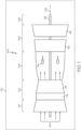
- FIG. 1 a functional block diagram of an exemplary gas turbine engine 100 is depicted.
- the engine 100 may be included on a vehicle 110 of any suitable type, such as an aircraft, rotorcraft, marine vessel, train, or other vehicle, and the engine 100 can propel or provide auxiliary power to the vehicle 110.
- the depicted engine 100 may be a single-spool turbo-shaft gas turbine propulsion engine.
- the engine 100 may generally include an intake section 101, a compressor section 102, a combustion section 104, a turbine section 106, and an exhaust section 108, which are arranged sequentially along a longitudinal axis 103.
- a downstream direction through the engine 100 may be defined generally along the axis 103 from the intake section 101 to the exhaust section 108.
- an upstream direction is defined from the exhaust section 108 to the intake section 101.
- the intake section 101 may receive an intake airstream indicated by arrows 107 in FIG. 1 .
- the compressor section 102 may include one or more compressor stages that draw air 107 downstream into the engine 100 and compress the air 107 to raise its pressure.
- the compressor section 102 includes two stages: a low pressure compressor stage 112 and a high pressure compressor stage 113.
- the compressor stages 112, 113 may be disposed sequentially along the axis 103 with the low pressure compressor stage 112 disposed upstream of the high pressure compressor stage 113. It will be appreciated that the engine 100 could be configured with more or less than this number of compressor stages.
- the compressed air from the compressor section 102 may be directed into the combustion section 104.
- the combustion section 104 which includes a combustor assembly 114, the compressed air is mixed with fuel supplied from a non-illustrated fuel source.
- the fuel- and-air mixture is combusted in the combustion section 104, and the high energy combusted air mixture is then directed into the turbine section 106.
- the turbine section 106 includes one or more turbines.
- the turbine section 106 includes two turbines: a high pressure turbine 116 and a low pressure turbine 118.
- the engine 100 could be configured with more or less than this number of turbines.
- the combusted air mixture from the combustion section 104 expands through each turbine 116, 118, causing it to rotate a power shaft 119.
- the combusted air mixture is then exhausted via the exhaust section 108.
- the power shaft 119 may be used to drive various devices within the engine 100 and/or within the vehicle 110.
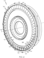
- the compressor section 102 will be discussed in greater detail according to example embodiments of the present disclosure.
- the low pressure compressor stage 112 is shown as an example; however, it will be appreciated that the features described may be included in the high pressure compressor stage 113.
- the compressor section 102 may include a case 120.
- the case 120 may be hollow and cylindrical in some embodiments.
- the case 120 includes a shroud 150 with a shroud surface 152 (e.g., an inner diameter surface of the shroud 150).
- the compressor section 102 inlcudes a rotor 122.
- the rotor 122 may include a wheel 124.
- the wheel 124 may be supported on the shaft 119 ( FIG. 1 ), which is hidden in FIGS. 2 and 3 for purposes of clarity.
- the wheel 124 may be centered on the axis 103.
- the rotor 122 may further include a plurality of blades 126, which extend radially from the wheel 124 and which may be spaced apart in a circumferential direction about the axis 103.
- the blades 126 of the rotor 122 may radially oppose the shroud surface 152.
- the rotor 122 may include a wheel 124.
- the wheel 124 may be supported on the shaft 119 ( FIG. 1 ), which is hidden in FIGS. 2 and 3 for purposes of clarity.
- the wheel 124 may be centered on the axis 103.
- the rotor 122 may further include a plurality of blades
- the wheel 124 and the plurality of blades 126 may rotate about the axis 103 relative to the case 120, the shroud 150, and the shroud surface 152 to generate an aft axial fluid flow through the compressor section 102 as will be discussed.
- the compressor section 102 may additionally include a stator 138.
- the stator 138 may include a plurality of stationary blades 140 and one or more support structures 142 that support the blades 140 in a fixed position on the case 120.
- the stator 138 may be disposed downstream of the wheel 124 and blades 126 of the rotor 122, and the stator 138 may direct air from the blades 126 further downstream through the engine 100.
- an inner radial end 130 is fixedly attached to the outer diameter of the wheel 124.
- the blade 126 also includes an outer radial edge or blade tip 132.
- the blade tip 132 is radially spaced apart from the inner radial end 130.
- the blade 126 further includes a leading edge 134, which extends radially between the inner radial end 130 and the blade tip 132.
- the blade 126 includes a trailing edge 136, which extends radially between the inner end and the blade tip 132, and which is spaced downstream of the leading edge 134 relative to the longitudinal axis 103.
- the blade tip 132 extends between the leading edge 134 and the trailing edge 136 extends generally along the longitudinal axis 103.
- the blades 126 may exhibit complex, three-dimensional curved surfaces and may be shaped so as to have a degree of helical twist about its respective radial axis and/or sweeping curvature in the downstream direction.
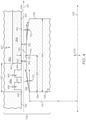
- the shroud 150 of the case 120 is shown in section view, and the blade 126 is shown with its outer profile (including the leading edge 134, the trailing edge 136, and the blade tip 132) projected onto a longitudinal plane (i.e., the plane of the paper).
- a radial axis 105 is also shown for reference purposes as well.
- the leading edge 134 and the trailing edge 136 may extend radially and may be substantially parallel to the radial axis 105 in some embodiments. Also, the blade tip 132 exhibits a certain contour that advantageously affects fluid flow through the compressor section 102. In other words, a radius 171 of the blade tip 132 (measured from the axis 103 to the blade tip 132 along the radial axis 105) may vary along the axis 103.
- the blade tip 132 is crowned as shown in FIG. 4 .
- the radius 171 of the blade tip 132 downstream axially from the leading edge 134 gradually increases
- the radius 171 may gradually change continuously in the axial direction between the leading edge 134 and the trailing edge 136.
- the profile of the blade tip 132 contours convexly continuously along the longitudinal axis 103 from the leading edge 134 to the trailing edge 136.
- the blade tip 132 defines a crown area 172.
- the crown area 172 represents an area or point on the blade tip 132 at which the radius 171 is at a maximum.
- the crown area 172 represents an apex of the crowned outer profile of the blade tip 132 with respect to the axis 103.
- the blade tip 132 decreases in radius 171 in the upstream and downstream directions from the crown area 172.
- the shroud 150 may be an annular component. In some embodiments represented in FIGS. 2-4 , the shroud 150 may have a radius (measured from the axis 103) that remains substantially constant along the axis 103. However, in other embodiments of the present disclosure (e.g., the embodiment of FIG. 5 ), the shroud may be tapered such that the radius varies longitudinally.
- the shroud 150 may define the shroud surface 152 on an inner diameter thereof.
- the shroud surface 152 may be centered about the axis 103. Additionally, the shroud surface 152 may be sub-divided relative to the blade 126 so as to include an upstream region 154, an opposing region 156, and a downstream region 158.
- the upstream region 154 of the shroud surface 152 may be disposed upstream of the blade 126.
- the opposing region 156 of the shroud surface 152 may directly oppose (in the radial direction) the blade tip 132.
- the downstream region 158 may be disposed downstream of the blade 126.
- a forward border 160 separates the upstream region 154 from the opposing region 156 in FIG. 2
- an aft border 162 separates the opposing region 156 from the downstream region 158.
- a clearance region 174 is defined between the blade tip 132 and the opposing region 156 of the shroud surface 152.
- a clearance dimension 176 (measured radially between the shroud surface 152 and the blade 126) varies along the longitudinal axis 103 from the leading edge 134 to the trailing edge 136.
- the clearance region 174 has a crowned or crown-like shape. In this case, the term "crowned" is used to define the difference between the minimum tip gap clearance 176 (at the crown area 172) and the maximum tip gap clearance 176 upstream of the crown area 172. Also, it will be appreciated that the clearance region 174 may be crowned when at the design operating condition of the compressor, which for an aircraft propulsion engine, would be a sea-level takeoff, cruise, or approach condition.
- the clearance dimension 176 proximate the crown area 172 (a crown clearance dimension) is smaller than the clearance dimension 176 proximate the leading edge 134 (a leading clearance dimension).
- the clearance dimension 176 proximate the crown area 172 is smaller than the clearance dimension 176 proximate the trailing edge 136.
- the clearance dimension 176 within the opposing region 156 may be smallest at the crown area 172.
- the clearance dimension 176 at the crown area 172 may be between approximately forty percent (40%) to sixty percent (60%) of the clearance dimension 176 at the leading edge 134.
- the rotor 122 is supported for rotation about the axis 103 to generate the aft axial fluid flow through the clearance region 174 (in a downstream direction) from the leading edge 134 to the trailing edge 136.
- the aft axial fluid flow, directed in the downstream direction, is represented by arrow 161 in FIG. 4 .
- the blade tip 132 may define a theta angle 170 between: 1) an imaginary axial line that is directed downstream and parallel to the axis 103; and 2) an intersecting imaginary tangential line that is directed generally downstream and tangent to the blade tip 132.
- a first theta angle (a leading edge theta angle at the leading edge 134) is indicated at 170 as an example.
- a second theta angle (an intermediate theta angle disposed longitudinally between the leading edge 134 and the trailing edge 136) is indicated in FIG. 4 at 170'.
- the theta angle 170 may be a positive angle at the leading edge 134, and the theta angle 170' may be a negative angle further downstream. More specifically, if the axial line defining the theta angle 170 represents zero degrees, then the tangential line defining the theta angle 170 is spaced at a positive angle therefrom; in contrast, if the axial line defining the theta angle 170' represents zero degrees, then the tangential line defining the theta angle 170' is spaced at a negative angle therefrom. Thus, those having ordinary skill in the art will understand that theta angle 170 may change along the blade tip 132 in the downstream direction relative to the axis 103.
- the theta angle 170 may gradually change along the blade tip 132. Also, in some embodiments, there may be a higher degree of change proximate the leading edge 134 than proximate the trailing edge 136. In some embodiments (e.g., the embodiment of FIG. 4 ), the theta angle 170 may change continuously along an entirety of the blade tip 13 in the downstream direction.
- the theta angle 170 either remains constant or decreases along the blade tip 132 in the downstream direction. Stated differently, the change in the theta angle 170 along the blade tip 132 in the downstream direction may be, at most, zero. In the embodiment of FIG. 4 , for example, the theta angle 170 does not increase in the downstream direction. Instead, the theta angle 170 continuously decreases along the blade tip 132 in the downstream direction.
- the theta angle 170 may be a positive angle at the leading edge 134. This may be the area at which the theta angle 170 of the blade tip 132 is greatest. Moving downstream along the blade tip 132 away from the leading edge 134, the theta angle 170 may gradually decrease. The theta angle 170 may be approximately zero degrees (0°) proximate the crown area 172. Moving even further downstream on the blade tip 132, the theta angle 170 may gradually decrease even further until reaching the trailing edge 136.
- FIG. 4 is merely an example and the blade tip 132 may be configured differently without departing from the scope of the present disclosure.
- the shroud 150 includes an abradable section 164 and a non-abradable section 166.
- the majority of the shroud 150 may be defined by a first material (i.e., a base material) of the non-abradable section 166, whereas the abradable section 164 may be constructed of a different material and/or construction that defines a minority of the shroud 150.
- the first material of the non-abradable section 166 may be formed of solid metal with high hardness, whereas the abradable section 164 may be constructed of a porous material with lower hardness.
- the abradable section 164 may be formed of a composite material with a matrix that wears away, for example, when contacted by the blade tip 132.
- the abradable section 164 may be embedded within the non-abradable section 166.
- the abradable section 164 may be an insert that is disposed within a recess, groove, or other aperture of the non-abradable section 166.
- the abradable section 164 may have a substantially rectangular cross section ( FIG. 4 ), and this cross section may extend in the circumferential direction about the axis 103.
- the abradable section 164 may include an upstream end 180 and an inner diameter surface 182.
- the abradable section 164 may also include a downstream end that is similar to the upstream end 180, but that is disposed downstream therefrom.
- the upstream end 180 may be recessed below the shroud surface 182 and embedded within the base material of the non-abradable section 166 such that the inner diameter surface 182 is exposed and flush with the abradable section 164 disposed immediately upstream. Accordingly, the abradable section 164 and the non-abradable section 166 cooperatively define the shroud surface 152 of the shroud 150.
- the non-abradable section 166 and the abradable section 164 define the opposing region 156 of the shroud surface 152 such that parts of the abradable section 164 and the non-abradable section 166 oppose the blade tip 132.
- the non-abradable section 166 may be disposed upstream of the abradable section 164 with respect to the axis 103. Specifically, the non-abradable section 166 may define the upstream region 154 and part of the opposing region 156 of the shroud surface 152.
- the abradable section 164 may define part of the opposing region 156 and the downstream region 158 of the shroud surface 152.
- the blade 126 is disposed relative to the shroud surface 152 such that the crown area 172 radially opposes the abradable section 164.
- the crown area 172 may be disposed axially downstream of the end 180 of the abradable section 164 (i.e., the crown area 172 may be disposed downstream of the non-abradable section 166). This ensures that, should the blade tip 132 contact the shroud 150, the blade tip 132 will contact abradable material that will wear away with little to no effect on operations of the compressor section 102.
- the upstream end 180 is embedded within the non-abradable portion 166, the upstream end 180 is protected from chipping away. Accordingly, the compressor section 102 may be very robust.
- the shroud 150 includes a casing treatment 186.
- the casing treatment 186 is configured to resist a reverse axial fluid flow (i.e., in a direction opposite the arrow 161) during near-stall operating conditions of the compressor section 102.
- the casing treatment 186 increases the stall margin of the compressor section 102 and/or reduces the deficit in the axial fluid flow, especially proximate the leading edge.
- the casing treatment 186 may include one or more grooves that are recessed radially into the shroud surface 152. As shown in the embodiment of FIG. 2 and 3 , grooves may be elongated, extending axially as well as circumferentially about the axis 103. However, as detailed above, the casing treatment 186 may be another feature without departing from the scope of the present disclosure (e.g., another aperture that is recessed into the shroud surface 152, a honeycomb structure that partly defines the shroud surface 152, a suction device, a blowing device, an active clearance control device, and a plasma flow control device).
- the casing treatment 186 may include a first groove 187 and a second groove 188 recessed radially into the shroud surface 152.
- the first and second grooves 187, 188 may have a rectangular (e.g., square) cross section, and this cross section of the grooves 187, 188 may extend circumferentially about the axis 103. Thus, these may be considered circumferential grooves. It will be appreciated, however, that at least one groove 187, 188 may have a triangular or wedge-shaped cross section.
- the major axis of the first and/or second grooves may extend generally parallel to the axis 103.
- at least one groove 187, 188 may extend helically about the axis 103 or in another direction with respect to the axis 103.
- the casing treatment 186 (i.e., the first and second grooves 187, 188) 2. in accordance with the present invention is provided in the non-abradable section 166 of the shroud 150 and partly within the opposing region 156 of the shroud surface 152 to radially oppose the blade tip 132 proximate the leading edge 134. Accordingly, the grooves 187, 188 may resist the reverse axial fluid flow during near-stall operating conditions. Also, because the grooves 187, 188 are provided in the non-abradable section 166, the grooves 187, 188 are unlikely to wear away, and the compressor section 102 may be very robust.
- electrodes may be disposed within and supported by the non-abradable section 166. These electrodes may be fixedly and robustly attached to the non-abradable section and may generate a voltage that ionizes the air, and the ionized air may be directed downstream via a selectively controlled electric field.
- MCF of the compressor section 102 may be a value between 0.33 and 0.62. This construction may provide ample space for one or more casing treatments 186 and the abradable section 164 and enhances manufacturability.
- CTL of the compressor section 102 may be a value between 0.60 to 0.90. This construction may provide ample space for one or more casing treatments 186 and the abradable section 164 and enhances manufacturability.
- the compressor section 102 may be manufactured in various ways.
- the case 120 may be formed initially.
- Portions of the non-abradable section 166 may be formed as a metallic cylinder.
- the grooves 187, 188 may be formed, for example, by cutting or otherwise removing material.
- the abradable section 164 may be inserted, embedded, attached, or otherwise provided to substantially complete the shroud 150.
- the blades 126 may be axially positioned as represented in FIG. 4 with the blade tips 132 opposing the hybrid shroud 150.
- parts of the shroud 150 may be additively manufactured (e.g., 3-D printing).
- the non-abradable section 166 may be additively manufactured to include the grooves 187, 188, and then the abradable section 164 may be attached and the rotor 122 positioned within the shroud 150.
- the shroud 150 may be additively manufactured to include the grooves 187, 188 (or other casing treatment 186) as well as the abradable section 164, and then the rotor 122 may be positioned within the shroud 150.
- the compressor section is illustrated according to additional embodiments of the present disclosure.
- the compressor section of FIG. 5 may represent the high-pressure compressor stage 113 of FIG. 1 .
- the compressor section of FIG. 5 may correspond to the embodiments of FIG. 4 except as noted. Components that correspond to those of FIG. 4 are indicated with corresponding reference numbers increased by 100.
- the shroud 250 may be tapered.
- the shroud 250 may taper such that the diameter gradually reduces in the downstream direction along the axis 103.
- the blade tip 232 is crowned.
- the theta angle 270 at the leading edge 234 may be a negative angle. The theta angle 270 may gradually reduce along the blade tip 232 in the downstream direction.
- the crown area 272 of the blade 226 opposes the abradable section 264.
- the casing treatment 286 e.g., grooves
- the non-abradable section 266 is included in the non-abradable section 266.
Landscapes
- Engineering & Computer Science (AREA)
- Mechanical Engineering (AREA)
- General Engineering & Computer Science (AREA)
- Physics & Mathematics (AREA)
- Fluid Mechanics (AREA)
- Structures Of Non-Positive Displacement Pumps (AREA)
Claims (14)
- Gasturbinentriebwerk (100), umfassend:eine Ummantelung (150, 250) mit einem abreibbaren Abschnitt (164, 264) und einem nicht abreibbaren Abschnitt (166, 266), die zusammenwirkend eine Ummantelungsfläche (152) definieren;einen Rotor (122), der zur Drehung innerhalb der Ummantelung gelagert ist, um eine hintere axiale Fluidströmung zu erzeugen, wobei der Rotor eine Schaufel (126, 226) mit einer Schaufelspitze (132, 232) einschließt, die so gewölbt ist, dass sie eine konvexe Krümmung zeigt und die dem abreibbaren Abschnitt und dem nicht abreibbaren Abschnitt der Ummantelungsfläche gegenüberliegt, wobei ein Wölbungsbereich (172) der Schaufelspitze dem abreibbaren Abschnitt gegenüberliegt;wobei sich die Schaufelspitze axial zwischen einer Vorderkante (134) und einer Hinterkante (136) der Schaufel erstreckt;wobei ein Freiraumbereich (174) zwischen der Schaufelspitze und der Ummantelungsfläche definiert ist; undwobei eine Wölbungsfreiraumabmessung (176, 276), die zwischen der Ummantelungsfläche (182) und der Schaufelspitze im Wölbungsbereich gemessen wird, kleiner ist als eine vordere Freiraumabmessung und eine hintere Freiraumabmessung, wobei die vordere Freiraumabmessung zwischen der Ummantelungsfläche und der Schaufelspitze in der Nähe der Vorderkante gemessen wird und die hintere Freiraumabmessung zwischen der Ummantelungsfläche und der Schaufelspitze in der Nähe der Hinterkante (136) gemessen wird,wobei das Gasturbinentriebwerk dadurch gekennzeichnet ist, dass ein Gehäusebehandlungsmerkmal (186, 286) in dem nicht abreibbaren Abschnitt (166, 266) der Ummantelung (150, 250) vorgesehen ist, um der Schaufelspitze (132, 232) des Rotors (122) gegenüber zu liegen.
- Gasturbinentriebwerk nach Anspruch 1, wobei die Wölbungsfreiraumabmessung zwischen vierzig Prozent (40 %) und sechzig Prozent (60 %) der vorderen Freiraumabmessung beträgt.
- Gasturbinentriebwerk nach Anspruch 1, wobei die Schaufelspitze einen Radius (171) aufweist, der sich von der Vorderkante zur Hinterkante kontinuierlich ändert.
- Gasturbinentriebwerk nach Anspruch 1, wobei der Rotor (122) zur Drehung um eine Längsachse gelagert ist; und
wobei die Ummantelung (250) einen Radius aufweist, der in einer nachgelagerten Richtung relativ zur Längsachse konstant bleibt. - Gasturbinentriebwerk nach Anspruch 1, wobei der Rotor (122) zur Drehung um eine Längsachse gelagert ist; und
wobei sich die Ummantelung (250) in einer nachgelagerten Richtung relativ zur Längsachse radial verjüngt. - Gasturbinentriebwerk nach Anspruch 1, wobei der Rotor (122) zur Drehung um eine Längsachse gelagert ist;wobei sich die Schaufelspitze axial zwischen einer Vorderkante und einer Hinterkante der Schaufel erstreckt;wobei in einer Projektion der Schaufelspitze auf eine Längsebene ein Thetawinkel zwischen einer imaginären axialen Linie und einer imaginären tangentialen Linie definiert ist, wobei die imaginäre axiale Linie parallel zur Längsachse verläuft und die imaginäre tangentiale Linie tangential zur Schaufelspitze verläuft; undwobei eine Änderung des Thetawinkels entlang der Schaufelspitze in einer nachgelagerten Richtung höchstens null ist.
- Gasturbinentriebwerk nach Anspruch 6, wobei der Thetawinkel nahe der Vorderkante ein positiver Winkel ist.
- Gasturbinentriebwerk nach Anspruch 6, wobei der Thetawinkel nahe der Vorderkante ein negativer Winkel ist.
- Gasturbinentriebwerk nach Anspruch 6, wobei sich der Thetawinkel entlang der Gesamtheit der Schaufelspitze in der nachgelagerten Richtung kontinuierlich ändert.
- Gasturbinentriebwerk nach Anspruch 1, wobei die Ummantelung (250) ein Basismaterial einschließt;wobei das Basismaterial den nicht abreibbaren Abschnitt der Ummantelung definiert;wobei der abreibbare Abschnitt ein vorgelagertes Ende und eine Innendurchmesserfläche einschließt, wobei das vorgelagerte Ende in das Basismaterial eingebettet ist und die Innendurchmesserfläche von dem Basismaterial freiliegt, um teilweise die Ummantelungsfläche zu definieren.
- Gasturbinentriebwerk nach Anspruch 1, wobei die Gehäusebehandlung mindestens eines von einer Öffnung, die in die Ummantelungsfläche eingelassen ist, einer Wabenstruktur, die teilweise die Ummantelungsfläche definiert, einer Ansaugvorrichtung, einer Gebläsevorrichtung, einer aktiven Freiraumsteuerungsvorrichtung und einer Plasmastromsteuerungsvorrichtung einschließt.
- Gasturbinentriebwerk nach Anspruch 1, wobei die Schaufelspitze der Ummantelungsfläche gegenüberliegt, um gemeinsam einen Freiraumbereich dazwischen zu definieren, wobei der Freiraumbereich eine Strömungsachse aufweist;wobei der abreibbare Abschnitt ein vorgelagertes Ende einschließt; undwobei der Wölbungsbereich dem vorgelagerten Ende relativ zur Strömungsachse nachgelagert angeordnet ist.
- Verfahren zur Herstellung eines Verdichterabschnitts eines Gasturbinentriebwerks, umfassend:Bereitstellen eines Gehäuses;Aufbringen eines abreibbaren Materials auf das Gehäuse, um einen abreibbaren Abschnitt einer Ummantelungsfläche zu definieren, wobei der abreibbare Abschnitt in einer axialen Richtung von einem nicht abreibbaren Abschnitt der Ummantelungsfläche beabstandet ist;Bereitstellen eines Gehäusebehandlungsmerkmals in dem nicht abreibbaren Abschnitt; undLagern eines Rotors zur Drehung innerhalb des Gehäuses, wobei der Rotor eine Schaufel mit einer Schaufelspitze einschließt, die so gewölbt ist, dass sie eine konvexe Krümmung aufweist und die dem abreibbaren Abschnitt und dem nicht abreibbaren Abschnitt der Ummantelungsfläche gegenüberliegt, wobei ein Wölbungsbereich der Schaufelspitze dem abreibbaren Abschnitt gegenüberliegt, wobei die Schaufelspitze so konfiguriert ist, dass sie sich axial zwischen einer Vorderkante und einer Hinterkante der Schaufel erstreckt;wobei ein Freiraumbereich zwischen der Schaufelspitze und der Ummantelungsfläche definiert ist; undwobei eine Wölbungsfreiraumabmessung, die zwischen der Ummantelungsfläche und der Schaufelspitze im Wölbungsbereich gemessen wird, kleiner ist als eine vordere Freiraumabmessung und eine hintere Freiraumabmessung, wobei die vordere Freiraumabmessung zwischen der Ummantelungsfläche und der Schaufelspitze in der Nähe der Vorderkante gemessen wird und die hintere Freiraumabmessung zwischen der Ummantelungsfläche und der Schaufelspitze in der Nähe der Hinterkante gemessen wird.
- Gasturbinentriebwerk nach Anspruch 1, wobei ein Verdichterabschnitt die Ummantelung (150, 250) mit dem abreibbaren Abschnitt (186, 286) und dem nicht abreibbaren Abschnitt (164, 264) definiert, die zusammenwirkend eine Ummantelungsfläche (152) definieren;wobei in einer Projektion der Schaufelspitze auf eine Längsebene ein Thetawinkel zwischen einer imaginären axialen Linie und einer imaginären tangentialen Linie definiert ist, wobei die imaginäre axiale Linie parallel zur Längsachse verläuft und die imaginäre tangentiale Linie tangential zur Schaufelspitze verläuft; undwobei eine Änderung des Thetawinkels entlang der Schaufelspitze in einer nachgelagerten Richtung höchstens null ist.
Priority Applications (1)
| Application Number | Priority Date | Filing Date | Title |
|---|---|---|---|
| EP22152127.1A EP4006313A1 (de) | 2018-12-28 | 2019-12-27 | Verdichterabschnitt eines gasturbinentriebwerks mit hybridummantelung mit gehäusebehandlung und abreibbarem abschnitt |
Applications Claiming Priority (1)
| Application Number | Priority Date | Filing Date | Title |
|---|---|---|---|
| US16/235,876 US10876423B2 (en) | 2018-12-28 | 2018-12-28 | Compressor section of gas turbine engine including hybrid shroud with casing treatment and abradable section |
Related Child Applications (2)
| Application Number | Title | Priority Date | Filing Date |
|---|---|---|---|
| EP22152127.1A Division-Into EP4006313A1 (de) | 2018-12-28 | 2019-12-27 | Verdichterabschnitt eines gasturbinentriebwerks mit hybridummantelung mit gehäusebehandlung und abreibbarem abschnitt |
| EP22152127.1A Division EP4006313A1 (de) | 2018-12-28 | 2019-12-27 | Verdichterabschnitt eines gasturbinentriebwerks mit hybridummantelung mit gehäusebehandlung und abreibbarem abschnitt |
Publications (2)
| Publication Number | Publication Date |
|---|---|
| EP3674520A1 EP3674520A1 (de) | 2020-07-01 |
| EP3674520B1 true EP3674520B1 (de) | 2022-02-23 |
Family
ID=69055799
Family Applications (2)
| Application Number | Title | Priority Date | Filing Date |
|---|---|---|---|
| EP19219934.7A Active EP3674520B1 (de) | 2018-12-28 | 2019-12-27 | Verdichterabschnitt eines gasturbinentriebwerks mit hybridummantelung mit gehäusebehandlung und abreibbarem abschnitt |
| EP22152127.1A Pending EP4006313A1 (de) | 2018-12-28 | 2019-12-27 | Verdichterabschnitt eines gasturbinentriebwerks mit hybridummantelung mit gehäusebehandlung und abreibbarem abschnitt |
Family Applications After (1)
| Application Number | Title | Priority Date | Filing Date |
|---|---|---|---|
| EP22152127.1A Pending EP4006313A1 (de) | 2018-12-28 | 2019-12-27 | Verdichterabschnitt eines gasturbinentriebwerks mit hybridummantelung mit gehäusebehandlung und abreibbarem abschnitt |
Country Status (2)
| Country | Link |
|---|---|
| US (2) | US10876423B2 (de) |
| EP (2) | EP3674520B1 (de) |
Families Citing this family (6)
| Publication number | Priority date | Publication date | Assignee | Title |
|---|---|---|---|---|
| US11215070B2 (en) * | 2019-12-13 | 2022-01-04 | Pratt & Whitney Canada Corp. | Dual density abradable panels |
| CN113389601B (zh) * | 2021-06-23 | 2022-08-23 | 江苏大学 | 一种叶顶带有孔腔的倾斜螺旋槽密封结构及叶轮机械 |
| US20230151825A1 (en) * | 2021-11-17 | 2023-05-18 | Pratt & Whitney Canada Corp. | Compressor shroud with swept grooves |
| US12270306B2 (en) | 2021-12-15 | 2025-04-08 | General Electric Company | Engine component with abradable material and treatment |
| CN118224120B (zh) * | 2024-01-15 | 2025-10-24 | 中水珠江规划勘测设计有限公司 | 一种抑制叶顶泄漏涡的圆弧型凹槽叶顶及具有其的叶片泵 |
| US12385408B1 (en) * | 2024-01-26 | 2025-08-12 | Rtx Corporation | Life and performance improvement trenches |
Family Cites Families (16)
| Publication number | Priority date | Publication date | Assignee | Title |
|---|---|---|---|---|
| US6527509B2 (en) * | 1999-04-26 | 2003-03-04 | Hitachi, Ltd. | Turbo machines |
| US6585479B2 (en) * | 2001-08-14 | 2003-07-01 | United Technologies Corporation | Casing treatment for compressors |
| GB0216952D0 (en) * | 2002-07-20 | 2002-08-28 | Rolls Royce Plc | Gas turbine engine casing and rotor blade arrangement |
| GB2407343B (en) | 2003-10-22 | 2006-04-19 | Rolls Royce Plc | An acoustic liner for a gas turbine engine casing |
| GB0526011D0 (en) * | 2005-12-22 | 2006-02-01 | Rolls Royce Plc | Fan or compressor casing |
| US20080063508A1 (en) | 2006-09-08 | 2008-03-13 | Barry Barnett | Fan case abradable |
| DE102008017844A1 (de) | 2008-04-08 | 2009-10-15 | Rolls-Royce Deutschland Ltd & Co Kg | Strömungsmaschine mit Fluid-Injektorbaugruppe |
| DE102008031982A1 (de) | 2008-07-07 | 2010-01-14 | Rolls-Royce Deutschland Ltd & Co Kg | Strömungsarbeitsmaschine mit Nut an einem Laufspalt eines Schaufelendes |
| DE102008052401A1 (de) * | 2008-10-21 | 2010-04-22 | Rolls-Royce Deutschland Ltd & Co Kg | Strömungsarbeitsmaschine mit Laufspalteinzug |
| US8337146B2 (en) * | 2009-06-03 | 2012-12-25 | Pratt & Whitney Canada Corp. | Rotor casing treatment with recessed baffles |
| JP4916560B2 (ja) * | 2010-03-26 | 2012-04-11 | 川崎重工業株式会社 | ガスタービンエンジンの圧縮機 |
| GB201017797D0 (en) * | 2010-10-21 | 2010-12-01 | Rolls Royce Plc | An aerofoil structure |
| US9115594B2 (en) * | 2010-12-28 | 2015-08-25 | Rolls-Royce Corporation | Compressor casing treatment for gas turbine engine |
| FR2995949B1 (fr) | 2012-09-25 | 2018-05-25 | Safran Aircraft Engines | Carter de turbomachine |
| EP2818724B1 (de) | 2013-06-27 | 2020-09-23 | MTU Aero Engines GmbH | Strömungsmaschine und Verfahren |
| US10648484B2 (en) | 2017-02-14 | 2020-05-12 | Honeywell International Inc. | Grooved shroud casing treatment for high pressure compressor in a turbine engine |
-
2018
- 2018-12-28 US US16/235,876 patent/US10876423B2/en active Active
-
2019
- 2019-12-27 EP EP19219934.7A patent/EP3674520B1/de active Active
- 2019-12-27 EP EP22152127.1A patent/EP4006313A1/de active Pending
-
2020
- 2020-11-05 US US17/090,039 patent/US11421544B2/en active Active
Also Published As
| Publication number | Publication date |
|---|---|
| EP3674520A1 (de) | 2020-07-01 |
| US11421544B2 (en) | 2022-08-23 |
| US10876423B2 (en) | 2020-12-29 |
| US20200208532A1 (en) | 2020-07-02 |
| US20210054761A1 (en) | 2021-02-25 |
| EP4006313A1 (de) | 2022-06-01 |
Similar Documents
| Publication | Publication Date | Title |
|---|---|---|
| EP3674520B1 (de) | Verdichterabschnitt eines gasturbinentriebwerks mit hybridummantelung mit gehäusebehandlung und abreibbarem abschnitt | |
| CN101131096B (zh) | 扩口形叶尖涡轮叶片 | |
| EP3361053B1 (de) | Behandlung eines gerillten mantelgehäuses für einen hochdruckverdichter in einem turbinentriebwerk | |
| US11378093B2 (en) | Throat distribution for a rotor and rotor blade having camber and location of local maximum thickness distribution | |
| JPH10502150A (ja) | 回転機械の圧縮領域のための流れ配向アッセンブリ | |
| US11280199B2 (en) | Throat distribution for a rotor and rotor blade having camber and location of local maximum thickness distribution | |
| US11015465B2 (en) | Compressor section of gas turbine engine including shroud with serrated casing treatment | |
| CN114562338A (zh) | 用于燃气涡轮发动机的可变导向叶片 | |
| EP3456919B1 (de) | Rotor, zugehöriges gasturbinentriebwerk und verfahren zum bilden eines rotors | |
| US20180128118A1 (en) | Turbine airfoil attachment with multi-radial serration profile | |
| CN108730034B (zh) | 涡轮发动机和用于涡轮发动机中的容纳组件 | |
| EP3919724B1 (de) | Charakteristische verteilung für das rotorblatt eines verstärkerrotors | |
| US11286779B2 (en) | Characteristic distribution for rotor blade of booster rotor | |
| EP3919723A1 (de) | Charakteristische verteilung für das rotorblatt eines verstärkerrotors | |
| US9976428B2 (en) | Turbine airfoil attachment with serration profile | |
| CN108730036B (zh) | 涡轮发动机和用于涡轮发动机中的容纳组件 | |
| EP4685339A1 (de) | Freitragende statorschaufel | |
| US12571320B2 (en) | Turbine blade tip geometry system and method for gas turbine engine | |
| US20260117654A1 (en) | Booster rotors and methods of operating gas turbine engines | |
| US20230382539A1 (en) | Aircraft engine with stator having varying geometry |
Legal Events
| Date | Code | Title | Description |
|---|---|---|---|
| PUAI | Public reference made under article 153(3) epc to a published international application that has entered the european phase |
Free format text: ORIGINAL CODE: 0009012 |
|
| STAA | Information on the status of an ep patent application or granted ep patent |
Free format text: STATUS: THE APPLICATION HAS BEEN PUBLISHED |
|
| AK | Designated contracting states |
Kind code of ref document: A1 Designated state(s): AL AT BE BG CH CY CZ DE DK EE ES FI FR GB GR HR HU IE IS IT LI LT LU LV MC MK MT NL NO PL PT RO RS SE SI SK SM TR |
|
| AX | Request for extension of the european patent |
Extension state: BA ME |
|
| STAA | Information on the status of an ep patent application or granted ep patent |
Free format text: STATUS: REQUEST FOR EXAMINATION WAS MADE |
|
| 17P | Request for examination filed |
Effective date: 20201221 |
|
| RBV | Designated contracting states (corrected) |
Designated state(s): AL AT BE BG CH CY CZ DE DK EE ES FI FR GB GR HR HU IE IS IT LI LT LU LV MC MK MT NL NO PL PT RO RS SE SI SK SM TR |
|
| RIC1 | Information provided on ipc code assigned before grant |
Ipc: F01D 11/12 20060101AFI20210715BHEP Ipc: F04D 29/52 20060101ALI20210715BHEP Ipc: F04D 29/68 20060101ALI20210715BHEP Ipc: F01D 5/20 20060101ALN20210715BHEP |
|
| RIC1 | Information provided on ipc code assigned before grant |
Ipc: F01D 5/20 20060101ALN20210730BHEP Ipc: F04D 29/68 20060101ALI20210730BHEP Ipc: F04D 29/52 20060101ALI20210730BHEP Ipc: F01D 11/12 20060101AFI20210730BHEP |
|
| GRAP | Despatch of communication of intention to grant a patent |
Free format text: ORIGINAL CODE: EPIDOSNIGR1 |
|
| STAA | Information on the status of an ep patent application or granted ep patent |
Free format text: STATUS: GRANT OF PATENT IS INTENDED |
|
| INTG | Intention to grant announced |
Effective date: 20210914 |
|
| GRAS | Grant fee paid |
Free format text: ORIGINAL CODE: EPIDOSNIGR3 |
|
| GRAA | (expected) grant |
Free format text: ORIGINAL CODE: 0009210 |
|
| STAA | Information on the status of an ep patent application or granted ep patent |
Free format text: STATUS: THE PATENT HAS BEEN GRANTED |
|
| AK | Designated contracting states |
Kind code of ref document: B1 Designated state(s): AL AT BE BG CH CY CZ DE DK EE ES FI FR GB GR HR HU IE IS IT LI LT LU LV MC MK MT NL NO PL PT RO RS SE SI SK SM TR |
|
| REG | Reference to a national code |
Ref country code: GB Ref legal event code: FG4D |
|
| REG | Reference to a national code |
Ref country code: CH Ref legal event code: EP |
|
| REG | Reference to a national code |
Ref country code: DE Ref legal event code: R096 Ref document number: 602019011856 Country of ref document: DE |
|
| REG | Reference to a national code |
Ref country code: AT Ref legal event code: REF Ref document number: 1470614 Country of ref document: AT Kind code of ref document: T Effective date: 20220315 |
|
| REG | Reference to a national code |
Ref country code: IE Ref legal event code: FG4D |
|
| REG | Reference to a national code |
Ref country code: LT Ref legal event code: MG9D |
|
| REG | Reference to a national code |
Ref country code: NL Ref legal event code: MP Effective date: 20220223 |
|
| REG | Reference to a national code |
Ref country code: AT Ref legal event code: MK05 Ref document number: 1470614 Country of ref document: AT Kind code of ref document: T Effective date: 20220223 |
|
| PG25 | Lapsed in a contracting state [announced via postgrant information from national office to epo] |
Ref country code: SE Free format text: LAPSE BECAUSE OF FAILURE TO SUBMIT A TRANSLATION OF THE DESCRIPTION OR TO PAY THE FEE WITHIN THE PRESCRIBED TIME-LIMIT Effective date: 20220223 Ref country code: RS Free format text: LAPSE BECAUSE OF FAILURE TO SUBMIT A TRANSLATION OF THE DESCRIPTION OR TO PAY THE FEE WITHIN THE PRESCRIBED TIME-LIMIT Effective date: 20220223 Ref country code: PT Free format text: LAPSE BECAUSE OF FAILURE TO SUBMIT A TRANSLATION OF THE DESCRIPTION OR TO PAY THE FEE WITHIN THE PRESCRIBED TIME-LIMIT Effective date: 20220623 Ref country code: NO Free format text: LAPSE BECAUSE OF FAILURE TO SUBMIT A TRANSLATION OF THE DESCRIPTION OR TO PAY THE FEE WITHIN THE PRESCRIBED TIME-LIMIT Effective date: 20220523 Ref country code: NL Free format text: LAPSE BECAUSE OF FAILURE TO SUBMIT A TRANSLATION OF THE DESCRIPTION OR TO PAY THE FEE WITHIN THE PRESCRIBED TIME-LIMIT Effective date: 20220223 Ref country code: LT Free format text: LAPSE BECAUSE OF FAILURE TO SUBMIT A TRANSLATION OF THE DESCRIPTION OR TO PAY THE FEE WITHIN THE PRESCRIBED TIME-LIMIT Effective date: 20220223 Ref country code: HR Free format text: LAPSE BECAUSE OF FAILURE TO SUBMIT A TRANSLATION OF THE DESCRIPTION OR TO PAY THE FEE WITHIN THE PRESCRIBED TIME-LIMIT Effective date: 20220223 Ref country code: ES Free format text: LAPSE BECAUSE OF FAILURE TO SUBMIT A TRANSLATION OF THE DESCRIPTION OR TO PAY THE FEE WITHIN THE PRESCRIBED TIME-LIMIT Effective date: 20220223 Ref country code: BG Free format text: LAPSE BECAUSE OF FAILURE TO SUBMIT A TRANSLATION OF THE DESCRIPTION OR TO PAY THE FEE WITHIN THE PRESCRIBED TIME-LIMIT Effective date: 20220523 |
|
| PG25 | Lapsed in a contracting state [announced via postgrant information from national office to epo] |
Ref country code: PL Free format text: LAPSE BECAUSE OF FAILURE TO SUBMIT A TRANSLATION OF THE DESCRIPTION OR TO PAY THE FEE WITHIN THE PRESCRIBED TIME-LIMIT Effective date: 20220223 Ref country code: LV Free format text: LAPSE BECAUSE OF FAILURE TO SUBMIT A TRANSLATION OF THE DESCRIPTION OR TO PAY THE FEE WITHIN THE PRESCRIBED TIME-LIMIT Effective date: 20220223 Ref country code: GR Free format text: LAPSE BECAUSE OF FAILURE TO SUBMIT A TRANSLATION OF THE DESCRIPTION OR TO PAY THE FEE WITHIN THE PRESCRIBED TIME-LIMIT Effective date: 20220524 Ref country code: FI Free format text: LAPSE BECAUSE OF FAILURE TO SUBMIT A TRANSLATION OF THE DESCRIPTION OR TO PAY THE FEE WITHIN THE PRESCRIBED TIME-LIMIT Effective date: 20220223 Ref country code: AT Free format text: LAPSE BECAUSE OF FAILURE TO SUBMIT A TRANSLATION OF THE DESCRIPTION OR TO PAY THE FEE WITHIN THE PRESCRIBED TIME-LIMIT Effective date: 20220223 |
|
| PG25 | Lapsed in a contracting state [announced via postgrant information from national office to epo] |
Ref country code: IS Free format text: LAPSE BECAUSE OF FAILURE TO SUBMIT A TRANSLATION OF THE DESCRIPTION OR TO PAY THE FEE WITHIN THE PRESCRIBED TIME-LIMIT Effective date: 20220623 |
|
| PG25 | Lapsed in a contracting state [announced via postgrant information from national office to epo] |
Ref country code: SM Free format text: LAPSE BECAUSE OF FAILURE TO SUBMIT A TRANSLATION OF THE DESCRIPTION OR TO PAY THE FEE WITHIN THE PRESCRIBED TIME-LIMIT Effective date: 20220223 Ref country code: SK Free format text: LAPSE BECAUSE OF FAILURE TO SUBMIT A TRANSLATION OF THE DESCRIPTION OR TO PAY THE FEE WITHIN THE PRESCRIBED TIME-LIMIT Effective date: 20220223 Ref country code: RO Free format text: LAPSE BECAUSE OF FAILURE TO SUBMIT A TRANSLATION OF THE DESCRIPTION OR TO PAY THE FEE WITHIN THE PRESCRIBED TIME-LIMIT Effective date: 20220223 Ref country code: EE Free format text: LAPSE BECAUSE OF FAILURE TO SUBMIT A TRANSLATION OF THE DESCRIPTION OR TO PAY THE FEE WITHIN THE PRESCRIBED TIME-LIMIT Effective date: 20220223 Ref country code: DK Free format text: LAPSE BECAUSE OF FAILURE TO SUBMIT A TRANSLATION OF THE DESCRIPTION OR TO PAY THE FEE WITHIN THE PRESCRIBED TIME-LIMIT Effective date: 20220223 Ref country code: CZ Free format text: LAPSE BECAUSE OF FAILURE TO SUBMIT A TRANSLATION OF THE DESCRIPTION OR TO PAY THE FEE WITHIN THE PRESCRIBED TIME-LIMIT Effective date: 20220223 |
|
| REG | Reference to a national code |
Ref country code: DE Ref legal event code: R097 Ref document number: 602019011856 Country of ref document: DE |
|
| PG25 | Lapsed in a contracting state [announced via postgrant information from national office to epo] |
Ref country code: AL Free format text: LAPSE BECAUSE OF FAILURE TO SUBMIT A TRANSLATION OF THE DESCRIPTION OR TO PAY THE FEE WITHIN THE PRESCRIBED TIME-LIMIT Effective date: 20220223 |
|
| PLBE | No opposition filed within time limit |
Free format text: ORIGINAL CODE: 0009261 |
|
| STAA | Information on the status of an ep patent application or granted ep patent |
Free format text: STATUS: NO OPPOSITION FILED WITHIN TIME LIMIT |
|
| 26N | No opposition filed |
Effective date: 20221124 |
|
| PG25 | Lapsed in a contracting state [announced via postgrant information from national office to epo] |
Ref country code: SI Free format text: LAPSE BECAUSE OF FAILURE TO SUBMIT A TRANSLATION OF THE DESCRIPTION OR TO PAY THE FEE WITHIN THE PRESCRIBED TIME-LIMIT Effective date: 20220223 |
|
| REG | Reference to a national code |
Ref country code: DE Ref legal event code: R119 Ref document number: 602019011856 Country of ref document: DE |
|
| P01 | Opt-out of the competence of the unified patent court (upc) registered |
Effective date: 20230525 |
|
| PG25 | Lapsed in a contracting state [announced via postgrant information from national office to epo] |
Ref country code: IT Free format text: LAPSE BECAUSE OF FAILURE TO SUBMIT A TRANSLATION OF THE DESCRIPTION OR TO PAY THE FEE WITHIN THE PRESCRIBED TIME-LIMIT Effective date: 20220223 |
|
| REG | Reference to a national code |
Ref country code: CH Ref legal event code: PL |
|
| REG | Reference to a national code |
Ref country code: BE Ref legal event code: MM Effective date: 20221231 |
|
| PG25 | Lapsed in a contracting state [announced via postgrant information from national office to epo] |
Ref country code: LU Free format text: LAPSE BECAUSE OF NON-PAYMENT OF DUE FEES Effective date: 20221227 |
|
| PG25 | Lapsed in a contracting state [announced via postgrant information from national office to epo] |
Ref country code: LI Free format text: LAPSE BECAUSE OF NON-PAYMENT OF DUE FEES Effective date: 20221231 Ref country code: IE Free format text: LAPSE BECAUSE OF NON-PAYMENT OF DUE FEES Effective date: 20221227 Ref country code: DE Free format text: LAPSE BECAUSE OF NON-PAYMENT OF DUE FEES Effective date: 20230701 Ref country code: CH Free format text: LAPSE BECAUSE OF NON-PAYMENT OF DUE FEES Effective date: 20221231 |
|
| PG25 | Lapsed in a contracting state [announced via postgrant information from national office to epo] |
Ref country code: BE Free format text: LAPSE BECAUSE OF NON-PAYMENT OF DUE FEES Effective date: 20221231 |
|
| PG25 | Lapsed in a contracting state [announced via postgrant information from national office to epo] |
Ref country code: HU Free format text: LAPSE BECAUSE OF FAILURE TO SUBMIT A TRANSLATION OF THE DESCRIPTION OR TO PAY THE FEE WITHIN THE PRESCRIBED TIME-LIMIT; INVALID AB INITIO Effective date: 20191227 |
|
| PG25 | Lapsed in a contracting state [announced via postgrant information from national office to epo] |
Ref country code: CY Free format text: LAPSE BECAUSE OF FAILURE TO SUBMIT A TRANSLATION OF THE DESCRIPTION OR TO PAY THE FEE WITHIN THE PRESCRIBED TIME-LIMIT Effective date: 20220223 |
|
| PG25 | Lapsed in a contracting state [announced via postgrant information from national office to epo] |
Ref country code: MK Free format text: LAPSE BECAUSE OF FAILURE TO SUBMIT A TRANSLATION OF THE DESCRIPTION OR TO PAY THE FEE WITHIN THE PRESCRIBED TIME-LIMIT Effective date: 20220223 |
|
| PG25 | Lapsed in a contracting state [announced via postgrant information from national office to epo] |
Ref country code: MC Free format text: LAPSE BECAUSE OF FAILURE TO SUBMIT A TRANSLATION OF THE DESCRIPTION OR TO PAY THE FEE WITHIN THE PRESCRIBED TIME-LIMIT Effective date: 20220223 |
|
| PG25 | Lapsed in a contracting state [announced via postgrant information from national office to epo] |
Ref country code: MC Free format text: LAPSE BECAUSE OF FAILURE TO SUBMIT A TRANSLATION OF THE DESCRIPTION OR TO PAY THE FEE WITHIN THE PRESCRIBED TIME-LIMIT Effective date: 20220223 |
|
| GBPC | Gb: european patent ceased through non-payment of renewal fee |
Effective date: 20231227 |
|
| PG25 | Lapsed in a contracting state [announced via postgrant information from national office to epo] |
Ref country code: MT Free format text: LAPSE BECAUSE OF FAILURE TO SUBMIT A TRANSLATION OF THE DESCRIPTION OR TO PAY THE FEE WITHIN THE PRESCRIBED TIME-LIMIT Effective date: 20220223 |
|
| PG25 | Lapsed in a contracting state [announced via postgrant information from national office to epo] |
Ref country code: GB Free format text: LAPSE BECAUSE OF NON-PAYMENT OF DUE FEES Effective date: 20231227 |
|
| PG25 | Lapsed in a contracting state [announced via postgrant information from national office to epo] |
Ref country code: GB Free format text: LAPSE BECAUSE OF NON-PAYMENT OF DUE FEES Effective date: 20231227 |
|
| PG25 | Lapsed in a contracting state [announced via postgrant information from national office to epo] |
Ref country code: TR Free format text: LAPSE BECAUSE OF FAILURE TO SUBMIT A TRANSLATION OF THE DESCRIPTION OR TO PAY THE FEE WITHIN THE PRESCRIBED TIME-LIMIT Effective date: 20220223 |
|
| PGFP | Annual fee paid to national office [announced via postgrant information from national office to epo] |
Ref country code: FR Payment date: 20251223 Year of fee payment: 7 |