EP3674521B1 - Passives schaufelspitzenspielkontrollsystem für ein gasturbinentriebwerk - Google Patents
Passives schaufelspitzenspielkontrollsystem für ein gasturbinentriebwerk Download PDFInfo
- Publication number
- EP3674521B1 EP3674521B1 EP19211684.6A EP19211684A EP3674521B1 EP 3674521 B1 EP3674521 B1 EP 3674521B1 EP 19211684 A EP19211684 A EP 19211684A EP 3674521 B1 EP3674521 B1 EP 3674521B1
- Authority
- EP
- European Patent Office
- Prior art keywords
- turbine
- cavity
- shroud
- tip clearance
- blade tip
- Prior art date
- Legal status (The legal status is an assumption and is not a legal conclusion. Google has not performed a legal analysis and makes no representation as to the accuracy of the status listed.)
- Active
Links
Images


Classifications
-
- F—MECHANICAL ENGINEERING; LIGHTING; HEATING; WEAPONS; BLASTING
- F01—MACHINES OR ENGINES IN GENERAL; ENGINE PLANTS IN GENERAL; STEAM ENGINES
- F01D—NON-POSITIVE DISPLACEMENT MACHINES OR ENGINES, e.g. STEAM TURBINES
- F01D11/00—Preventing or minimising internal leakage of working-fluid, e.g. between stages
- F01D11/08—Preventing or minimising internal leakage of working-fluid, e.g. between stages for sealing space between rotor blade tips and stator
- F01D11/14—Adjusting or regulating tip-clearance, i.e. distance between rotor-blade tips and stator casing
- F01D11/16—Adjusting or regulating tip-clearance, i.e. distance between rotor-blade tips and stator casing by self-adjusting means
- F01D11/18—Adjusting or regulating tip-clearance, i.e. distance between rotor-blade tips and stator casing by self-adjusting means using stator or rotor components with predetermined thermal response, e.g. selective insulation, thermal inertia, differential expansion
-
- F—MECHANICAL ENGINEERING; LIGHTING; HEATING; WEAPONS; BLASTING
- F01—MACHINES OR ENGINES IN GENERAL; ENGINE PLANTS IN GENERAL; STEAM ENGINES
- F01D—NON-POSITIVE DISPLACEMENT MACHINES OR ENGINES, e.g. STEAM TURBINES
- F01D25/00—Component parts, details, or accessories, not provided for in, or of interest apart from, other groups
- F01D25/08—Cooling; Heating; Heat-insulation
- F01D25/10—Heating, e.g. warming-up before starting
-
- F—MECHANICAL ENGINEERING; LIGHTING; HEATING; WEAPONS; BLASTING
- F01—MACHINES OR ENGINES IN GENERAL; ENGINE PLANTS IN GENERAL; STEAM ENGINES
- F01D—NON-POSITIVE DISPLACEMENT MACHINES OR ENGINES, e.g. STEAM TURBINES
- F01D25/00—Component parts, details, or accessories, not provided for in, or of interest apart from, other groups
- F01D25/08—Cooling; Heating; Heat-insulation
- F01D25/12—Cooling
-
- F—MECHANICAL ENGINEERING; LIGHTING; HEATING; WEAPONS; BLASTING
- F02—COMBUSTION ENGINES; HOT-GAS OR COMBUSTION-PRODUCT ENGINE PLANTS
- F02C—GAS-TURBINE PLANTS; AIR INTAKES FOR JET-PROPULSION PLANTS; CONTROLLING FUEL SUPPLY IN AIR-BREATHING JET-PROPULSION PLANTS
- F02C9/00—Controlling gas-turbine plants; Controlling fuel supply in air- breathing jet-propulsion plants
- F02C9/16—Control of working fluid flow
- F02C9/18—Control of working fluid flow by bleeding, bypassing or acting on variable working fluid interconnections between turbines or compressors or their stages
-
- F—MECHANICAL ENGINEERING; LIGHTING; HEATING; WEAPONS; BLASTING
- F02—COMBUSTION ENGINES; HOT-GAS OR COMBUSTION-PRODUCT ENGINE PLANTS
- F02K—JET-PROPULSION PLANTS
- F02K3/00—Plants including a gas turbine driving a compressor or a ducted fan
- F02K3/02—Plants including a gas turbine driving a compressor or a ducted fan in which part of the working fluid by-passes the turbine and combustion chamber
- F02K3/04—Plants including a gas turbine driving a compressor or a ducted fan in which part of the working fluid by-passes the turbine and combustion chamber the plant including ducted fans, i.e. fans with high volume, low pressure outputs, for augmenting the jet thrust, e.g. of double-flow type
- F02K3/06—Plants including a gas turbine driving a compressor or a ducted fan in which part of the working fluid by-passes the turbine and combustion chamber the plant including ducted fans, i.e. fans with high volume, low pressure outputs, for augmenting the jet thrust, e.g. of double-flow type with front fan
-
- F—MECHANICAL ENGINEERING; LIGHTING; HEATING; WEAPONS; BLASTING
- F01—MACHINES OR ENGINES IN GENERAL; ENGINE PLANTS IN GENERAL; STEAM ENGINES
- F01D—NON-POSITIVE DISPLACEMENT MACHINES OR ENGINES, e.g. STEAM TURBINES
- F01D19/00—Starting of machines or engines; Regulating, controlling, or safety means in connection therewith
- F01D19/02—Starting of machines or engines; Regulating, controlling, or safety means in connection therewith dependent on temperature of component parts, e.g. of turbine-casing
-
- F—MECHANICAL ENGINEERING; LIGHTING; HEATING; WEAPONS; BLASTING
- F05—INDEXING SCHEMES RELATING TO ENGINES OR PUMPS IN VARIOUS SUBCLASSES OF CLASSES F01-F04
- F05D—INDEXING SCHEME FOR ASPECTS RELATING TO NON-POSITIVE-DISPLACEMENT MACHINES OR ENGINES, GAS-TURBINES OR JET-PROPULSION PLANTS
- F05D2220/00—Application
- F05D2220/30—Application in turbines
- F05D2220/32—Application in turbines in gas turbines
- F05D2220/321—Application in turbines in gas turbines for a special turbine stage
- F05D2220/3212—Application in turbines in gas turbines for a special turbine stage the first stage of a turbine
-
- F—MECHANICAL ENGINEERING; LIGHTING; HEATING; WEAPONS; BLASTING
- F05—INDEXING SCHEMES RELATING TO ENGINES OR PUMPS IN VARIOUS SUBCLASSES OF CLASSES F01-F04
- F05D—INDEXING SCHEME FOR ASPECTS RELATING TO NON-POSITIVE-DISPLACEMENT MACHINES OR ENGINES, GAS-TURBINES OR JET-PROPULSION PLANTS
- F05D2220/00—Application
- F05D2220/30—Application in turbines
- F05D2220/32—Application in turbines in gas turbines
- F05D2220/323—Application in turbines in gas turbines for aircraft propulsion, e.g. jet engines
-
- F—MECHANICAL ENGINEERING; LIGHTING; HEATING; WEAPONS; BLASTING
- F05—INDEXING SCHEMES RELATING TO ENGINES OR PUMPS IN VARIOUS SUBCLASSES OF CLASSES F01-F04
- F05D—INDEXING SCHEME FOR ASPECTS RELATING TO NON-POSITIVE-DISPLACEMENT MACHINES OR ENGINES, GAS-TURBINES OR JET-PROPULSION PLANTS
- F05D2240/00—Components
- F05D2240/10—Stators
- F05D2240/11—Shroud seal segments
-
- F—MECHANICAL ENGINEERING; LIGHTING; HEATING; WEAPONS; BLASTING
- F05—INDEXING SCHEMES RELATING TO ENGINES OR PUMPS IN VARIOUS SUBCLASSES OF CLASSES F01-F04
- F05D—INDEXING SCHEME FOR ASPECTS RELATING TO NON-POSITIVE-DISPLACEMENT MACHINES OR ENGINES, GAS-TURBINES OR JET-PROPULSION PLANTS
- F05D2260/00—Function
- F05D2260/20—Heat transfer, e.g. cooling
- F05D2260/205—Cooling fluid recirculation, i.e. after cooling one or more components is the cooling fluid recovered and used elsewhere for other purposes
-
- F—MECHANICAL ENGINEERING; LIGHTING; HEATING; WEAPONS; BLASTING
- F05—INDEXING SCHEMES RELATING TO ENGINES OR PUMPS IN VARIOUS SUBCLASSES OF CLASSES F01-F04
- F05D—INDEXING SCHEME FOR ASPECTS RELATING TO NON-POSITIVE-DISPLACEMENT MACHINES OR ENGINES, GAS-TURBINES OR JET-PROPULSION PLANTS
- F05D2260/00—Function
- F05D2260/60—Fluid transfer
- F05D2260/606—Bypassing the fluid
-
- F—MECHANICAL ENGINEERING; LIGHTING; HEATING; WEAPONS; BLASTING
- F05—INDEXING SCHEMES RELATING TO ENGINES OR PUMPS IN VARIOUS SUBCLASSES OF CLASSES F01-F04
- F05D—INDEXING SCHEME FOR ASPECTS RELATING TO NON-POSITIVE-DISPLACEMENT MACHINES OR ENGINES, GAS-TURBINES OR JET-PROPULSION PLANTS
- F05D2270/00—Control
- F05D2270/40—Type of control system
- F05D2270/42—Type of control system passive or reactive, e.g. using large wind vanes
Definitions
- the present invention relates to a gas turbine engine including a passive blade tip clearance control system.
- Gas turbine engines are used to power aircraft, watercraft, power generators, and the like.
- Gas turbine engines typically include a compressor, a combustor, and a turbine.
- the compressor compresses air drawn into the engine and delivers high pressure air to the combustor.
- fuel is mixed with the high pressure air and is ignited.
- Products of the combustion reaction in the combustor are directed into the turbine where work is extracted to drive the compressor and, sometimes, an output shaft. Left-over products of the combustion are exhausted out of the turbine and may provide thrust in some applications.
- a blade track or other structure arranged radially outward of the rotating blades may block combustion products from passing over the blades without causing the blades to rotate, thereby contributing to lost performance within the gas turbine engine. Excessive contact between the rotating blades and the blade track during engine operation may cause degradation of the blades. Excessive clearance between the rotating blades and the blade track may cause unacceptable efficiencies of the gas turbine engine. In view of the above considerations, managing clearance between the blade track and the rotating blades remains an area of interest.
- Clearance control is known from e.g. US4023919 where a thermally actuated valve is used to expose a support structure to different temperature mediums; EP1630385 , US3742705 or EP1004759 where air is supplied through a heat exchanger of a cooling duct to cool an engine casing; US2011206502 where a thermal shield protects a thermal support.
- the present invention concerns a gas turbine engine as defined in independent claim 1 and may comprise one or more of the following additional features and combinations thereof.
- the passive blade tip clearance control system is configured to heat the inner case during start-up conditions of the gas turbine engine and is configured to cool the inner case during cruise conditions.
- the cavity formed between the outer case and the inner case is sealed off from a gas path of the high-pressure section of the turbine such that the temperature of gases within the cavity controls a blade tip clearance gap while allowing for pressure within the cavity to be less than pressure within the primary gas path of the high-pressure section.
- the outer case includes an annular duct that extends circumferentially around the central reference axis and defines a manifold and the inlet is fluidly coupled to the manifold.
- the passive blade tip clearance control system includes a plurality of inlet conduits fluidly coupled to the manifold and spaced apart circumferentially around the central reference axis and a plurality of outlets spaced apart circumferentially around the central reference axis that extend through the manifold and are offset from each inlet conduit.
- the inner case includes a plurality of turbulators coupled to an upper surface of the inner case within the cavity radially outward of the second turbine blade stage to increase heat transfer between the pressurized bleed air and the inner case directly outward of the second turbine blade stage.
- the inner case includes a panel that is coupled to the variable-diameter turbine shroud ring and a flange coupled to an axially forward end of the panel,
- the flange is coupled to the outer case and has a U-shape when viewed circumferentially so that the flange is configured to flex as the inner case moves radially inward and outward relative to the outer case.
- An illustrative aerospace gas turbine engine 10 includes a fan 12, a compressor 14, a combustor 16, and a turbine 18 as shown in Fig. 1 .
- the fan 12 is driven by the turbine 18 and provides thrust for propelling an air vehicle.
- the compressor 14 compresses and delivers air to the combustor 16.
- the combustor 16 mixes fuel with the compressed air received from the compressor 14 and ignites the fuel.
- the hot, high-pressure products of the combustion reaction in the combustor 16 are directed into the turbine 18 to cause the turbine 18 to rotate about a central reference axis 11 and drive the compressor 14 and the fan 12.
- the turbine 18 includes a high-pressure section 20 fluidly coupled to the combustor 16 to receive combustion gases generated by fuel burned in the combustor and a low-pressure section 22 fluidly coupled to receive the combustion gases exiting the high-pressure section 20.
- the turbine 18 may further include one or more intermediate sections between the high pressure section 20 and the low-pressure section 22.
- the high-pressure section 20 includes a turbine wheel 24 mounted for rotation about the central reference axis 11, a variable-diameter turbine shroud ring 26 that extends around the turbine wheel 24, and a plurality of blades 30 mounted to the turbine wheel 24 as shown in Figs. 1 and 2 .
- the blades 30 are configured to interact with the hot gases in the gas path to cause rotation of the turbine wheel 24.
- the turbine shroud ring 26 is coupled to a shroud-ring support 34 radially outward from the blades 30 to provide a radially outer boundary of the gas path.
- Each of the blades 30 is spaced apart from the turbine shroud ring 26 by a clearance gap 36 that is defined between a tip of each blade 30 and the turbine shroud ring 26.
- the hot gases may cause various components within the turbine 18 to expand in response to the higher temperatures caused by the combustion of the pressurized air.
- One such component that may undergo thermal expansion is the shroud-ring support 34.
- the shroud-ring support 34 may have a first diameter under start-up conditions and a second diameter under operating conditions that is greater than the first diameter due to the increased temperature of the engine after a period of time of operation.
- the turbine wheel 24 may have a first diameter under start-up conditions and a second diameter under operating conditions that is greater than the first diameter due to the increased temperature of the engine after a period of time of operation.
- the turbine wheel 24 changes from the first diameter to the second diameter in a shorter period of time than the shroud-ring support 34.
- the high pressure section 20 further includes a passive blade tip clearance control system 40 that defines a cavity 50 radially outward from the turbine wheel 24 of the high pressure section 20 as shown in Figs. 1 and 2 .
- the cavity 50 is sealed from the gas path of the turbine 18 such that the temperature of gases within the cavity 50 controls the gap 36 while allowing for pressure within the cavity 50 to be less than pressure within the primary gas path of the high pressure turbine section 20.
- the passive blade tip clearance control system 40 supplies pressurized air having a first temperature to the cavity 50.
- the temperature of the pressurized air is greater than the temperature of the shroud-ring support 34 to heat the shroud-ring support 34.
- Heating the shroud-ring support 34 during start-up opens the gap 36 to accommodate the faster change in diameter of the turbine wheel 24. In other words, heating the shroud-ring support 34 during start-up allows the thermal growth of the shroud-ring support 34 to more closely match the thermal growth of the turbine wheel 24.
- the passive blade tip clearance control system 40 supplies the same pressurized air to the cavity 50.
- the temperature of the shroud-ring support 34 becomes greater than the temperature of the pressurized air.
- the pressurized air cools the shroud-ring support 34 to close the gap 36 and improve efficiencies of the engine 10.
- the passive blade tip clearance control system 40 includes an inlet conduit 42, an outer case 44 and the shroud-ring support 34, or inner case 34.
- the outer case 44 and the inner case 34 define the cavity 50.
- the inlet conduit 42 defines a bleed-air passageway 46 that is fluidly coupled to the compressor 14 and the cavity 50 without interruption from a valve or any other active blade tip clearance control device.
- a cooling-air passageway 47 extends from the cavity 50 to the low pressure section 22 of the turbine 18.
- the blade tip clearance control system 40 conducts pressurized air from the compressor 14 into the cavity 50 to control blade tip clearance in the high pressure section 20 and then reuses the air downstream of the cavity 50 in the low pressure section 22.
- the temperature and motion of the shroud-ring support 34 is controlled based on the operating conditions of the engine without active control of the pressurized bleed air provided to the cavity.
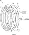
- the outer case 44 includes an outer panel 52, an inner panel 54 spaced apart radially from the outer panel 52, and an annular duct 56 as shown in Figs. 2 and 3 .
- the outer panel 52 defines a radially-outer boundary of the cavity 50.
- the inner panel 54 extends axially forward from the annular duct 56 within the cavity 50 such that the inner panel 54 is spaced apart radially between both the outer panel 52 and the shroud-ring support 34.
- the annular duct 56 defines a manifold 58 that extends circumferentially around the central reference axis 11 as shown in Fig. 3 .
- the bleed-air passageway 46 has an outlet 48 that opens into the manifold 58 to deliver the pressurized air into the manifold 58.
- the shroud-ring support 34 or inner case 34, includes a panel 60, a flange 62 on an axially forward end of the panel 60, and a plurality of mounts 63 that extends radially downward from the panel 60 as shown in Fig. 2 .
- the panel 60 defines a radially-inner boundary of the cavity 50.
- the flange 62 has a generally U-shape cross section when viewed circumferentially and extends radially outward into engagement with the outer case 44 to provide the cavity 50.
- the plurality of mounts 63 interface with corresponding mounts 65 coupled to the turbine shroud ring 26 to mount the turbine shroud ring 26 to the shroud-ring support 34.
- the mounts 63, 65 are generally L-shaped when viewed circumferentially, however, in other embodiments, the mounts may have any suitable shape. Additionally, one or more fasteners may be used to mount the turbine shroud ring 26 to the shroud-ring support 34.
- the annular duct 56 is a tubular member to define the manifold 58 as shown in Fig. 2 .
- the annular duct 56 is formed to include a gap 64 that extends circumferentially around the reference axis 11 with the annular duct 56.
- the gap 64 acts as an outlet to the manifold and opens into the cavity 50.
- the inner panel 54 is coupled to the annular duct and extends axially forward from the annular duct 56 into the cavity to provide the gap 64 along an axial length 66 of the inner panel 54 into the cavity 50.
- the inner panel 54 cooperates with the annular duct 56 to narrow the cavity 50 along the length 66. As the cavity 50 is narrowed, the pressurized air is accelerated in that area to encourage heat transfer between the pressurized air and a portion of the shroud-ring support 34 corresponding to the length 66 to control blade tip clearance in that area.
- the inner panel 54 is adjustable axially and may be extended or retracted axially to adjust the length 66 and, thus, the portion of the shroud-ring support 34 that is controlled. Additionally, the length 66 of the inner panel 54 may be increased or decreased based on the operating conditions of the particular engine in which the passive blade tip clearance control system 40 is included. In one embodiment, an amount of radial movement of the shroud-ring support 34 is related to the length 66 of the inner panel 54. For example, if more blade tip clearance is required in a particular engine, the length 66 of the inner panel 54 may be increased to provide greater heat transfer across a larger portion of the shroud-ring support 34 and, thus, a larger change in diameter of the shroud-ring support 34 relative to the reference axis 11. However, it should be noted that any suitable length 66 may be used depending on the particular application.
- the shroud-ring support 34 may further include a plurality of turbulators 90 formed on the shroud-ring support 34 as shown in Fig. 2 .
- the turbulators 90 are positioned in the gap 64 within the length 66 of the inner panel 54 to increase the surface area of the shroud-ring support 34 in that area.
- the turbulators 90 increase heat transfer from the pressurized air to the shroud-ring support 34 to help drive the shroud-ring support 34 radially inward and outward.
- the turbulators 90 may extend along the shroud-ring support 34 a greater or lesser distance than the length 66 of the inner panel 54.
- the flange 62 is configured to flex to allow the shroud-ring support 34 to move radially inward and outward as the pressurized air drives movement of the shroud-ring support 34.
- the flange 62 includes a radially inner flex-section 68, a radially outer flex-section 70, and a mount section 72 as shown in Fig. 2 .
- the inner-flex section 68 is coupled to the panel 60 and extends axially forward from the panel 60.
- the outer flex-section 70 is coupled to the inner flex-section 68 and extends axially aft from the inner flex-section 68.
- the inner and outer flex sections 68, 70 are arranged at an angle 74 relative to one another to provide the generally u-shape of the flange 62.
- the angle 74 between the inner flex-section 68 and the outer flex section 70 increases as the diameter of the shroud-ring support 34 decreases.
- the angle 74 between the inner flex-section 68 and the outer flex section 70 decreases as the diameter of the shroud-ring support 34 increases.
- the mount section 72 extends radially outward from the outer flex-section 70 and couples to the outer case 44 to mount the shroud-ring support 34 and the turbine shroud ring 26 to the outer case 44.
- the passive blade tip clearance control system 40 includes a plurality of inlet conduits 42 spaced circumferentially around the central reference axis 11 as shown in Fig. 3 .
- Each of the inlet conduits 42 is a tubular member and defines a bleed air passageway 46 that opens into the manifold 58.
- the pressurized bleed air is conducted into the manifold 58, through the gap 64 between the shroud-ring support 34 and the inner panel 54 of the outer case 44, and then through one or more outlets 76 where the pressurized air is then sent to the low pressure section 22 of the turbine 18.
- the outlet(s) 76 may be tubular members similar to the inlet conduits 42 or may be defined by the outer and/or the inner cases 44, 34 as will be described in greater detail below.
- the outlets 76 are spaced circumferentially around the reference axis 11.
- the outlets 76 are tubular members defining passageways that extend axially through the manifold 58 from the cavity 50 toward the low pressure section 22 of the turbine 18.
- Each of the outlets 76 is spaced apart circumferentially from neighboring inlet conduits 42 so that the pressurized air travels circumferentially from the inlet conduits 42 toward the outlets 76 to deliver the pressurized air over the entire circumferential area of the shroud-ring support 34.
- the outlets 76 are spaced radially outward from the inner panel 54 of the outer case 44 such that the pressurized air travels radially outward over the inner panel 54 and then through the outlets 76.
- the high pressure section 20 of the turbine 18 includes a first turbine blade stage 80, a second turbine blade stage 82 axially aft of the first turbine blade stage 80, and a vane stage 84 axially between the first and second turbine blade stages 80, 82.
- the passive blade tip clearance control system 40 is sized and located to control a blade tip clearance gap 36 radially between second turbine blade stage 82 and the turbine shroud ring 26.
- the second turbine blade stage 82 generally falls within the length 66 of the inner panel 54 of the outer case 44.
- Pressurized air traveling through the gap 64 along the length 66 drives motion of the shroud-ring support 34 to move the turbine shroud ring 26 radially inward or outward directly adjacent the second turbine blade stage 82.
- the length 66 of the inner panel 54 may be increased or decreased to target additional and/or other turbine blade stages, such as first turbine blade stage 80, and control the blade tip clearance of those turbine blade stages.
- the turbulators 90 facilitate heat transfer in the gap 64.
- FIG. 4 Another embodiment of a passive blade tip clearance control system 240 in accordance with the present disclosure is shown in Fig. 4 .
- the passive blade tip clearance control system 240 is substantially similar to the passive blade tip clearance control system 40 shown in Figs. 1-3 and described herein. Accordingly, similar reference numbers in the 200 series indicate features that are common between the passive blade tip clearance control system 40 and the passive blade tip clearance control system 240.
- the description of the passive blade tip clearance control system 40 is incorporated by reference to apply to the passive blade tip clearance control system 240, except in instances when it conflicts with the specific description and the drawings of the passive blade tip clearance control system 240.
- the passive blade tip clearance control system 240 includes an inlet conduit 242, an outer case 244 and a shroud-ring support 234, or inner case 234.
- the outer case 244 and the shroud-ring support 234 define a cavity 250 radially therebetween.
- the inlet conduit 242 defines a bleed-air passageway 246 that is fluidly coupled between the compressor 14 and the cavity 250 without interruption from a valve or any other active blade tip clearance control device.
- a cooling-air passageway extends from the cavity 250 to the low pressure section 22 of the turbine 18 and is also uninterrupted from a valve or active blade tip clearance device.
- the blade tip clearance control system 240 conducts pressurized air from the compressor 14 into the cavity 250 to control blade tip clearance in the high pressure section 20 and then reuses the air downstream of the cavity 250 in the low pressure section 22. Furthermore, the temperature and motion of the shroud-ring support 234 is controlled based on the operating conditions of the engine without active control of the pressurized bleed air provided to the cavity.
- the outer case 244 includes an outer panel 252, an inner panel 254 spaced apart radially from the outer panel 252, and a linking segment 256 connecting the outer panel 252 to the inner panel 254 as shown in Fig. 4 .
- the outer panel 252 and the inner panel 254 cooperate to define a radially-outer boundary of the cavity 250.
- the inner panel 254 is spaced apart radially between both the outer panel 252 and the shroud-ring support 234.
- the linking segment 256 extends from the outer panel 252 radially inward to the inner panel 254 at an angle to narrow the cavity 250 between the inner panel 254 and the turbine-shroud ring 234 to provide a gap 264 similarly to the passive blade tip clearance control system 40 described above.
- the shroud-ring support 234, or inner case 234, includes a panel 260, a flange 262 on an axially forward end of the panel 260, and a plurality of mounts 263 that extend radially downward from the panel 260 as shown in Fig. 4 .
- the panel 260 defines a radially-inner boundary of the cavity 250.
- the flange 262 has a generally U-shape cross section when viewed circumferentially and extends radially outward into engagement with the outer case 244 to provide the cavity 250.
- the flange 262 is configured to flex to allow the shroud-ring support 234 to move radially inward and outward as the pressurized air drives movement of the shroud-ring support 234.
- the plurality of mounts 263 interface with corresponding mounts 65 coupled to the turbine shroud ring 26 to mount the turbine shroud ring 26 to the shroud-ring support 234.
- the mounts 263, 65 are generally L-shaped when viewed circumferentially, however, in other embodiments, the mounts may have any suitable shape. Additionally, one or more fasteners may be used to mount the turbine shroud ring 26 to the shroud-ring support 234.
- the bleed-air passageway 246 of the inlet conduit 242 has an outlet 248 that opens into the cavity 250 through the outer panel 252 axially forward from the inner panel 254 and the linking segment 256 as shown in Fig. 4 .
- the pressurized air flows radially through the outlet 248 and axially aft through the cavity 250 where it is accelerated between the inner panel 254 and the shroud-ring support 234 along a length 266 of the inner panel 254.
- the length 266 of the inner panel 254 corresponds to a portion of the shroud-ring support 234 to encourage heat transfer between the pressurized air and the shroud-ring support 234 in that area.
- the inner panel 254 is adjustable axially and may be extended or retracted axially to adjust the length 266 and, thus, the portion of the shroud-ring support 234 that is controlled.
- the size of the outer panel 252 or the linking segment 256 may also be adjusted in view of the size of the inner panel 254.
- length 266 of the inner panel 254 may be increased or decreased based on the operating conditions of the particular engine in which the passive blade tip clearance control system is included. In one embodiment, an amount of radial movement of the shroud-ring support 234 is related to the length 266 of the inner panel 254.
- the length 266 of the inner panel 254 may be increased to provide greater heat transfer across a larger portion of the shroud-ring support 234 and, thus, a larger change in diameter of the shroud-ring support 234 relative to the reference axis 11.
- any suitable length 266 may be used depending on the particular application.
- the shroud-ring support 234 may further include a plurality of turbulators 290 formed on the shroud-ring support 234 as shown in Fig. 4 .
- the turbulators 290 are positioned in the gap 264 within the length 266 of the inner panel 254 to increase the surface area of the shroud-ring support 234 in that area.
- the turbulators 290 increase heat transfer from the pressurized air to the shroud-ring support 234 to help drive the shroud-ring support 234 radially inward and outward.
- the turbulators 290 may extend along the shroud-ring support 234 a greater or lesser distance than the length 266 of the inner panel 254.
- the passive blade tip clearance control system 240 includes at least one outlet 276 down steam of the gap 264 as shown in Fig. 4 .
- the pressurized bleed air is conducted through the gap 264 between the shroud-ring support 234 and the inner panel 254 of the outer case 244 and then through the one or more outlets 276 where the pressurized air is then sent to the low pressure section 22 of the turbine 18.
- the outlet(s) 276 are a void defined between aft ends of the outer case 244 the shroud-ring support 234.
- the passive blade tip clearance control system 240 is sized and located to control the blade tip clearance gap 36 radially between second turbine blade stage 82 and the turbine shroud ring 26.
- the second turbine blade stage 82 generally falls within the length 266 of the inner panel 254 of the outer case 244. Pressurized air traveling through the gap 264 along the length 266 drives motion of the shroud-ring support 234 to move the turbine shroud ring 26 radially inward or outward directly outboard of the second turbine blade stage 82.
- the length 266 of the inner panel 254 may be increased or decreased to target additional and/or other turbine blade stages, such as first turbine blade stage 80, and control the blade tip clearance of those turbine blade stages.
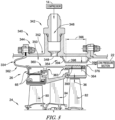
- FIG. 5 Another embodiment of a passive blade tip clearance control system 340 in accordance with the present disclosure is shown in Fig. 5 .
- the passive blade tip clearance control system 340 is substantially similar to the passive blade tip clearance control system 40 shown in Figs. 1-3 and described herein. Accordingly, similar reference numbers in the 300 series indicate features that are common between the passive blade tip clearance control system 40 and the passive blade tip clearance control system 340.
- the description of the passive blade tip clearance control system 40 is incorporated by reference to apply to the passive blade tip clearance control system 340, except in instances when it conflicts with the specific description and the drawings of the passive blade tip clearance control system 340.
- the passive blade tip clearance control system 340 includes an inlet conduit 342, an outer case 344 and a shroud-ring support 334, or inner case 334.
- the outer case 344 and the shroud-ring support 334 define a cavity 350 radially therebetween.
- the inlet conduit 342 defines a bleed-air passageway 346 that is fluidly coupled between the compressor 14 and the cavity 350 without interruption from a valve or any other active blade tip clearance control device.
- a cooling-air passageway extends from the cavity 350 to the low pressure section 22 of the turbine 18 and is also uninterrupted from a valve or active blade tip clearance device.
- the blade tip clearance control system 340 conducts pressurized air from the compressor 14 into the cavity 350 to control blade tip clearance in the high pressure section 20 and then reuses the air downstream of the cavity 350 in the low pressure section 22. Furthermore, the temperature and motion of the shroud-ring support 334 is controlled based on the operating conditions of the engine without active control of the pressurized bleed air provided to the cavity.
- the outer case 344 includes an outer panel 352 and an inner panel 354 as shown in Fig. 5 .
- the outer panel 352 and the inner panel 354 cooperate to define a radially-outer boundary of the cavity 350.
- the inner panel 354 is coupled to the outer panel 352 and is spaced apart radially outward of the shroud-ring support 334.
- the inner panel 354 is arranged to narrow the cavity 350 between the inner panel 354 and the turbine-shroud ring 334 to provide a gap 364 similarly to the passive blade tip clearance control system 40 described above.
- the shroud-ring support 334 or inner case 334, includes a panel 360, a flange 362 on an axially forward end of the panel 360, and a plurality of mounts 363 that extends radially downward from the panel 360 as shown in Fig. 5 .
- the panel 360 defines a radially-inner boundary of the cavity 350.
- the flange 362 has a generally U-shape cross section when viewed circumferentially and extends radially outward into engagement with the outer case 344 to provide the cavity 350.
- the flange 362 is configured to flex to allow the shroud-ring support 334 to move radially inward and outward as the pressurized air drives movement of the shroud-ring support 334.
- the plurality of mounts 363 interface with corresponding mounts 65 coupled to the turbine shroud ring 26 to mount the turbine shroud ring 26 to the shroud-ring support 334.
- the mounts 363, 65 are generally L-shaped when viewed circumferentially, however, in other embodiments, the mounts may have any suitable shape. Additionally, one or more fasteners may be used to mount the turbine shroud ring 26 to the shroud-ring support 334.
- the bleed-air passageway 346 of the inlet conduit 342 has an outlet 348 that opens into the cavity 350 through the outer panel 352 axially forward from the inner panel 354 as shown in Fig. 5 .
- the pressurized air flows radially through the outlet 348 and axially aft through the cavity 350 where it is accelerated between the inner panel 354 and the shroud-ring support 334 along a length 366 of the inner panel 354.
- the length 366 of the inner panel 354 corresponds to a portion of the shroud-ring support 334 to encourage heat transfer between the pressurized air and the shroud-ring support 334 in that area.
- the inner panel 354 is a separate component that is mounted to a radially-inner surface of the outer panel 352 as shown in Fig. 5 .
- the inner panel 354 includes an axially-forward segment 394, an axially-aft segment 396, and a middle segment 398 extending between the axially-forward segment 394 and the axially-aft segment 396.
- the axially-forward segment 394 extends radially inward at an angle relative to the reference axis 11 to the middle segment 398.
- the axially-aft segment 396 extends radially outward at an angle relative to the reference axis 11 from the middle segment 398 to the outer panel 352.
- the axially-forward segment 394 and the axially-aft segment 396 cooperate to locate the middle segment 398 in spaced-apart relation to the outer panel 352 and the shroud-ring support 334 and to narrow the cavity 350 along the length 366 of the inner panel 354.
- the middle segment 398 is generally parallel with the shroud-ring support 334 to provide a constant gap 364 between the middle segment 398 and the shroud-ring support 334.
- the segments 394, 396 may be coupled to the outer panel 352 by welding, brazing, mechanical fasteners or any other suitable means of mounting the inner panel 354 to the outer panel 352.
- the inner panel 354 is adjustable axially and may be extended or retracted axially to adjust the length 366 and, thus, the portion of the shroud-ring support 334 that is controlled. More particularly, the length of the middle segment 398 is increased or decreased in some embodiments. Additionally, length 366 of the inner panel 354 may be increased or decreased based on the operating conditions of the particular engine in which the passive blade tip clearance control system is included. In one embodiment, an amount of radial movement of the shroud-ring support 334 is related to the length 366 of the inner panel 354.
- the length 366 of the inner panel 354 may be increased to provide greater heat transfer across a larger portion of the shroud-ring support 334 and, thus, a larger change in diameter of the shroud-ring support 334 relative to the reference axis 11.
- any suitable length 366 may be used depending on the particular application.
- the shroud-ring support 334 may further include a plurality of turbulators 390 formed on the shroud-ring support 334 as shown in Fig. 5 .
- the turbulators 390 are positioned in the gap 364 and within the length 366 of the inner panel 354 to increase the surface area of the shroud-ring support 334 in that area.
- the turbulators 390 increase heat transfer from the pressurized air to the shroud-ring support 334 to help drive the shroud-ring support 334 radially inward and outward.
- the turbulators 390 may extend along the shroud-ring support 334 a greater or lesser distance than the length 366 of the inner panel 354.
- the passive blade tip clearance control system 340 includes at least one outlet 376 downstream of the gap 364 as shown in Fig. 5 .
- the pressurized bleed air is conducted through the gap 364 between the shroud-ring support 334 and the inner panel 354 of the outer case 344 and then through the one or more outlets 376 where the pressurized air is then sent to the low pressure section 22 of the turbine 18.
- the outlet(s) 376 are a void defined between aft ends of the outer case 344 the shroud-ring support 334.
- the passive blade tip clearance control system 340 is sized and located to control the blade tip clearance gap 36 radially between second turbine blade stage 82 and the turbine shroud ring 26.
- the second turbine blade stage 82 generally falls within the length 366 of the inner panel 354 of the outer case 344. Pressurized air traveling through the gap 364 along the length 366 drives motion of the shroud-ring support 334 to move the turbine shroud ring 26 radially inward or outward directly outboard of the second turbine blade stage 82.
- the length 366 of the inner panel 254 may be increased or decreased to target additional and/or other turbine blade stages, such as first turbine blade stage 80, and control the blade tip clearance of those turbine blade stages.
- the present disclosure relates to a passive tip clearance control system for either high or low pressure turbines.
- the passive blade tip clearance control system may heat the case during the initial part of the mission when the thermal and mechanical growth of the rotor (or turbine wheel 24) tends to outpace the thermal growth of the case, and then cool the case during the cruise portion of the mission when the case tends to thermally expand away from the rotor.
- This system may open the tip clearance 36 during the initial part of the mission to avoid contact between the blades and blade track (contact may result in a permanent increase in tip clearance), and tightens the tip clearance 36 during the cruise portion of the mission to improve efficiency.
- the passive blade tip clearance control system may provide these effects in a simple and robust way without the need of active valves, mechanical actuators, or complex control systems that use air impingement, valves, mechanical actuation, or some combination of these to control tip clearance.
Landscapes
- Engineering & Computer Science (AREA)
- Mechanical Engineering (AREA)
- General Engineering & Computer Science (AREA)
- Chemical & Material Sciences (AREA)
- Combustion & Propulsion (AREA)
- Physics & Mathematics (AREA)
- Fluid Mechanics (AREA)
- Turbine Rotor Nozzle Sealing (AREA)
Claims (8)
- Gasturbinentriebwerk (10), umfassend:einen Verdichter (14), der dazu konfiguriert ist, Luft unter Druck zu setzen, die sich entlang eines primären Gaspfads des Gasturbinentriebwerks (10) bewegt,eine Brennkammer (16), die fluidisch an den Verdichter (14) gekoppelt ist, um unter Druck gesetzte Luft aufzunehmen, die von dem Verdichter (14) abgegeben wird, und dazu konfiguriert ist, Kraftstoff zu zünden, der mit der unter Druck gesetzten Luft gemischt ist, undeine Turbine (18), die Folgendes beinhaltet: (i) einen Hochdruckabschnitt (20), der fluidisch an die Brennkammer (16) gekoppelt ist, um Verbrennungsgase aufzunehmen, die durch in der Brennkammer (16) verbrannten Kraftstoff erzeugt werden, und (ii) einen Niederdruckabschnitt (22), der fluidisch gekoppelt ist, um die aus dem Hochdruckabschnitt (20) austretenden Verbrennungsgase aufzunehmen,wobei der Hochdruckabschnitt (20) ein Turbinenrad (24), das zur Rotation um eine zentrale Referenzachse (11) montiert ist, einen Turbinenmantelring (26) mit variablem Durchmesser, der sich um das Turbinenrad (24) erstreckt, und ein passives Schaufelspitzenspielkontrollsystem (40) beinhaltet, das einen Mantelringträger (34) beinhaltet, der an den Turbinenmantelring (26) mit variablem Durchmesser gekoppelt ist, der dazu konfiguriert ist, eine Bewegung des Turbinenmantelrings (26) mit variablem Durchmesser auf Grundlage der Temperatur des Mantelringträgers (34) radial nach innen oder außen anzutreiben und mindestens teilweise einen Hohlraum (50) zu definieren, der sich radial außerhalb des Turbinenmantelrings (26) mit variablem Durchmesser befindet, undwobei der Hohlraum (50) fluidisch an einen Zapfluftdurchgang (46), der sich ohne Unterbrechung durch ein Ventil von dem Verdichter (14) zu dem Hohlraum (50) erstreckt, und einen Kühlluftdurchgang (47) gekoppelt ist, der sich derart von dem Hohlraum (50) zu dem Niederdruckabschnitt (22) erstreckt, dass unter Druck gesetzte Zapfluft von dem Verdichter (14) zu dem Hohlraum (50) des passiven Schaufelspitzenspielkontrollsystems (40) geleitet wird, sodass die Temperatur und Bewegung des Mantelringträgers (34) auf Grundlage der Betriebsbedingungen des Gasturbinentriebwerks (10) ohne aktive Kontrolle der dem Hohlraum (50) bereitgestellten unter Druck gesetzten Zapfluft kontrolliert wird;wobei das passive Schaufelspitzenspielkontrollsystem (40) ferner eine Einlassleitung (42), die an das Außengehäuse (44) gekoppelt ist und in den Hohlraum (50) mündet, und einen Auslass (76) beinhaltet, wobei die Einlassleitung (42) dazu konfiguriert ist, die unter Druck gesetzte Zapfluft von dem Verdichter (14) in den Hohlraum (50) und den Auslass (76) zu leiten, der dazu konfiguriert ist, die unter Druck gesetzte Zapfluft von dem Hohlraum (50) zu dem Niederdruckabschnitt (22) der Turbine (18) zu leiten;wobei das passive Schaufelspitzenspielkontrollsystem (40) ferner ein Außengehäuse (44) beinhaltet und der Mantelringträger (34) durch ein Innengehäuse (34) bereitgestellt wird, das radial innerhalb des Außengehäuses (44) montiert ist, um den Hohlraum (50) radial dazwischen zu definieren, und dadurch gekennzeichnet, dassder Hochdruckabschnitt (20) der Turbine (18) eine erste Turbinenschaufelstufe (80), eine zweite Turbinenschaufelstufe (82) axial hinter der ersten Turbinenschaufelstufe (80) und eine Leitschaufelstufe (84) axial zwischen der ersten und zweiten Turbinenschaufelstufe (80, 82) beinhaltet und das passive Schaufelspitzenspielkontrollsystem (40) dazu konfiguriert ist, einen Schaufelspitzenspielspalt (36) radial zwischen der zweiten Turbinenschaufelstufe (82) und dem Turbinenmantelring (26) mit variablem Durchmesser zu kontrollieren,das Außengehäuse (44) eine Außenverkleidung (52), die um einen ersten Abstand von der zentralen Referenzachse (11) beabstandet ist, und eine Innenverkleidung (54) beinhaltet, die um einen zweiten Abstand, der kleiner als der erste Abstand ist, von der zentralen Referenzachse (11) beabstandet ist;die Innenverkleidung (54) radial außerhalb der zweiten Turbinenschaufelstufe (82) positioniert ist, sodass der Hohlraum (50) außerhalb der zweiten Turbinenschaufelstufe (82) verengt ist;die Außenverkleidung (52) axial von der Innenverkleidung (54) beabstandet ist; unddie Innenverkleidung (54) axial einstellbar ist, um auf zusätzliche Turbinenschaufelstufen abzuzielen, die in dem Hochdruckabschnitt (20) der Turbine (18) beinhaltet sind.
- Gasturbinentriebwerk (10) nach Anspruch 1, wobei das Außengehäuse (44) einen ringförmigen Kanal (56) beinhaltet, der sich in Umfangsrichtung um die zentrale Referenzachse (11) erstreckt und einen Krümmer (58) definiert, und die Einlassleitung (42) fluidisch an den Krümmer (58) gekoppelt ist.
- Gasturbinentriebwerk (10) nach Anspruch 2, wobei das passive Schaufelspitzenspielkontrollsystem (40) eine Vielzahl von Einlassleitungen (42), die fluidisch an den Krümmer (58) gekoppelt und in Umfangsrichtung um die zentrale Referenzachse (11) beabstandet sind, und eine Vielzahl von Auslässen (76) beinhaltet, die in Umfangsrichtung um die zentrale Referenzachse (11) beabstandet sind, die sich durch den Krümmer (58) erstrecken und in Umfangsrichtung zu jeder Einlassleitung (42) versetzt sind.
- Gasturbinentriebwerk (10) nach einem der vorhergehenden Ansprüche, wobei das passive Schaufelspitzenspielkontrollsystem (40) dazu konfiguriert ist, das Innengehäuse (34) während Startbedingungen des Gasturbinentriebwerks (10) zu erwärmen, und dazu konfiguriert ist, das Innengehäuse (34) während Fahrtbedingungen zu kühlen.
- Gasturbinentriebwerk (10) nach einem der vorhergehenden Ansprüche, wobei der zwischen dem Außengehäuse (44) und dem Innengehäuse (34) gebildete Hohlraum (50) gegenüber einem Gaspfad des Hochdruckabschnitts (20) der Turbine (18) derart abgedichtet ist, dass die Temperatur von Gasen innerhalb des Hohlraums (50) einen Schaufelspitzenspielraumspalt (36) kontrolliert, während zugelassen wird, dass der Druck innerhalb des Hohlraums (50) geringer ist als der Druck innerhalb des primären Gaspfads des Hochdruckabschnitts (20).
- Gasturbinentriebwerk (10) nach Anspruch 1, wobei das Innengehäuse (34) eine Vielzahl von Turbulatoren (90) beinhaltet, die radial außerhalb der zweiten Turbinenschaufelstufe (82) an eine obere Fläche des Innengehäuses (34) innerhalb des Hohlraums (50) gekoppelt sind, um die Wärmeübertragung zwischen der unter Druck gesetzten Zapfluft und dem Innengehäuse (34) direkt außerhalb der zweiten Turbinenschaufelstufe (82) zu erhöhen.
- Gasturbinentriebwerk (10) nach einem der vorhergehenden Ansprüche, wobei das Innengehäuse (34) eine Verkleidung (60), die an den Turbinenmantelring (26) mit variablem Durchmesser gekoppelt ist, und einen Flansch (62) beinhaltet, der an ein axial vorderes Ende der Verkleidung (60) gekoppelt ist.
- Gasturbinentriebwerk (10) nach Anspruch 7, wobei der Flansch (62) an das Außengehäuse (44) gekoppelt ist und in Umfangsrichtung betrachtet eine U-Form aufweist, sodass der Flansch (62) dazu konfiguriert ist, sich zu biegen, wenn sich das Innengehäuse (34) bezogen auf das Außengehäuse (44) radial nach innen und außen bewegt.
Applications Claiming Priority (1)
| Application Number | Priority Date | Filing Date | Title |
|---|---|---|---|
| US16/233,964 US11015475B2 (en) | 2018-12-27 | 2018-12-27 | Passive blade tip clearance control system for gas turbine engine |
Publications (2)
| Publication Number | Publication Date |
|---|---|
| EP3674521A1 EP3674521A1 (de) | 2020-07-01 |
| EP3674521B1 true EP3674521B1 (de) | 2023-05-17 |
Family
ID=68699244
Family Applications (1)
| Application Number | Title | Priority Date | Filing Date |
|---|---|---|---|
| EP19211684.6A Active EP3674521B1 (de) | 2018-12-27 | 2019-11-27 | Passives schaufelspitzenspielkontrollsystem für ein gasturbinentriebwerk |
Country Status (3)
| Country | Link |
|---|---|
| US (1) | US11015475B2 (de) |
| EP (1) | EP3674521B1 (de) |
| CA (1) | CA3055948A1 (de) |
Families Citing this family (7)
| Publication number | Priority date | Publication date | Assignee | Title |
|---|---|---|---|---|
| US10941709B2 (en) * | 2018-09-28 | 2021-03-09 | Pratt & Whitney Canada Corp. | Gas turbine engine and cooling air configuration for turbine section thereof |
| US11156110B1 (en) * | 2020-08-04 | 2021-10-26 | General Electric Company | Rotor assembly for a turbine section of a gas turbine engine |
| US11492924B1 (en) * | 2021-04-26 | 2022-11-08 | General Electric Company Polska sp. z o.o | Embedded electric machine cooling |
| GB2614760A (en) * | 2022-01-13 | 2023-07-19 | Rolls Royce Plc | Turbine for gas turbine engine |
| US11702951B1 (en) * | 2022-06-10 | 2023-07-18 | Pratt & Whitney Canada Corp. | Passive cooling system for tip clearance optimization |
| US20230417150A1 (en) * | 2022-06-22 | 2023-12-28 | Pratt & Whitney Canada Corp. | Augmented cooling for tip clearance optimization |
| US12546261B1 (en) * | 2025-03-25 | 2026-02-10 | Rolls-Royce North American Technologies Inc. | Compressor bleed air collector and exhaust ducting for gas turbine engine systems |
Family Cites Families (37)
| Publication number | Priority date | Publication date | Assignee | Title |
|---|---|---|---|---|
| US3814313A (en) * | 1968-10-28 | 1974-06-04 | Gen Motors Corp | Turbine cooling control valve |
| US3742705A (en) | 1970-12-28 | 1973-07-03 | United Aircraft Corp | Thermal response shroud for rotating body |
| US4023919A (en) * | 1974-12-19 | 1977-05-17 | General Electric Company | Thermal actuated valve for clearance control |
| US4329114A (en) | 1979-07-25 | 1982-05-11 | The United States Of America As Represented By The Administrator Of The National Aeronautics And Space Administration | Active clearance control system for a turbomachine |
| GB2169962B (en) | 1985-01-22 | 1988-07-13 | Rolls Royce | Blade tip clearance control |
| GB2236147B (en) | 1989-08-24 | 1993-05-12 | Rolls Royce Plc | Gas turbine engine with turbine tip clearance control device and method of operation |
| US5018942A (en) | 1989-09-08 | 1991-05-28 | General Electric Company | Mechanical blade tip clearance control apparatus for a gas turbine engine |
| US5104287A (en) | 1989-09-08 | 1992-04-14 | General Electric Company | Blade tip clearance control apparatus for a gas turbine engine |
| US5116199A (en) | 1990-12-20 | 1992-05-26 | General Electric Company | Blade tip clearance control apparatus using shroud segment annular support ring thermal expansion |
| GB9103809D0 (en) | 1991-02-23 | 1991-04-10 | Rolls Royce Plc | Blade tip clearance control apparatus |
| GB2310255B (en) | 1996-02-13 | 1999-06-16 | Rolls Royce Plc | A turbomachine |
| FR2751694B1 (fr) * | 1996-07-25 | 1998-09-04 | Snecma | Agencement et procede de reglage de diametre d'anneau de stator |
| DE19756734A1 (de) | 1997-12-19 | 1999-06-24 | Bmw Rolls Royce Gmbh | Passives Spalthaltungssystem einer Gasturbine |
| US5993150A (en) | 1998-01-16 | 1999-11-30 | General Electric Company | Dual cooled shroud |
| US6227800B1 (en) | 1998-11-24 | 2001-05-08 | General Electric Company | Bay cooled turbine casing |
| FR2829176B1 (fr) * | 2001-08-30 | 2005-06-24 | Snecma Moteurs | Carter de stator de turbomachine |
| US6925814B2 (en) | 2003-04-30 | 2005-08-09 | Pratt & Whitney Canada Corp. | Hybrid turbine tip clearance control system |
| US20050109016A1 (en) | 2003-11-21 | 2005-05-26 | Richard Ullyott | Turbine tip clearance control system |
| US7269955B2 (en) | 2004-08-25 | 2007-09-18 | General Electric Company | Methods and apparatus for maintaining rotor assembly tip clearances |
| DE502005006421D1 (de) | 2005-04-14 | 2009-02-26 | Rolls Royce Deutschland | Anordnung zur inneren passiven Laufspalteinstellung bei einer Hochdruckturbine |
| US7708518B2 (en) | 2005-06-23 | 2010-05-04 | Siemens Energy, Inc. | Turbine blade tip clearance control |
| US7785063B2 (en) | 2006-12-15 | 2010-08-31 | Siemens Energy, Inc. | Tip clearance control |
| US8126628B2 (en) | 2007-08-03 | 2012-02-28 | General Electric Company | Aircraft gas turbine engine blade tip clearance control |
| US20110206502A1 (en) * | 2010-02-25 | 2011-08-25 | Samuel Ross Rulli | Turbine shroud support thermal shield |
| GB201004381D0 (en) | 2010-03-17 | 2010-04-28 | Rolls Royce Plc | Rotor blade tip clearance control |
| US8668431B2 (en) | 2010-03-29 | 2014-03-11 | United Technologies Corporation | Seal clearance control on non-cowled gas turbine engines |
| WO2011123106A1 (en) | 2010-03-31 | 2011-10-06 | United Technologies Corporation | Turbine blade tip clearance control |
| US9458855B2 (en) | 2010-12-30 | 2016-10-04 | Rolls-Royce North American Technologies Inc. | Compressor tip clearance control and gas turbine engine |
| US9316111B2 (en) | 2011-12-15 | 2016-04-19 | Pratt & Whitney Canada Corp. | Active turbine tip clearance control system |
| US9598975B2 (en) | 2013-03-14 | 2017-03-21 | Rolls-Royce Corporation | Blade track assembly with turbine tip clearance control |
| US20150167488A1 (en) | 2013-12-18 | 2015-06-18 | John A. Orosa | Adjustable clearance control system for airfoil tip in gas turbine engine |
| EP3040518B1 (de) | 2014-12-16 | 2017-04-26 | Rolls-Royce plc | Spitzenabstandssteuerung für turbinenschaufeln |
| EP3040519B1 (de) | 2014-12-16 | 2017-04-26 | Rolls-Royce plc | Spitzenabstandssteuerung für turbinenschaufeln |
| US9784117B2 (en) | 2015-06-04 | 2017-10-10 | United Technologies Corporation | Turbine engine tip clearance control system with rocker arms |
| US10316686B2 (en) | 2015-12-04 | 2019-06-11 | United Technologies Corporation | High response turbine tip clearance control system |
| GB201521937D0 (en) | 2015-12-14 | 2016-01-27 | Rolls Royce Plc | Gas turbine engine turbine cooling system |
| US10329941B2 (en) | 2016-05-06 | 2019-06-25 | United Technologies Corporation | Impingement manifold |
-
2018
- 2018-12-27 US US16/233,964 patent/US11015475B2/en active Active
-
2019
- 2019-09-19 CA CA3055948A patent/CA3055948A1/en active Pending
- 2019-11-27 EP EP19211684.6A patent/EP3674521B1/de active Active
Also Published As
| Publication number | Publication date |
|---|---|
| US20200208533A1 (en) | 2020-07-02 |
| EP3674521A1 (de) | 2020-07-01 |
| US11015475B2 (en) | 2021-05-25 |
| CA3055948A1 (en) | 2020-06-27 |
Similar Documents
| Publication | Publication Date | Title |
|---|---|---|
| EP3674521B1 (de) | Passives schaufelspitzenspielkontrollsystem für ein gasturbinentriebwerk | |
| US11021990B2 (en) | Shroud sealing for a gas turbine engine | |
| US11092013B2 (en) | Modulated turbine cooling system | |
| US11015613B2 (en) | Aero loading shroud sealing | |
| EP3181829B1 (de) | Gasturbinenmotorturbinenkühlsystem | |
| EP2075437B1 (de) | System zur Kühlung einer Gasturbine aus mehreren Quellen | |
| EP1398474B1 (de) | Zapfluft-Gehäuse für einen Verdichter | |
| EP1630385B1 (de) | Verfahren und Vorrichtung zur Aufrechterhaltung des Schaufelspitzenspiels einer Rotoranordnung | |
| JP6401581B2 (ja) | 表面冷却器の支持機構 | |
| CN114991963B (zh) | 具有热交换器的三流发动机 | |
| EP2942490A1 (de) | Turbinenabstandssteuerungssystem und verfahren für verbesserte kraftstoffverbrennung in einem gasturbinenmotor mit variablem zyklus | |
| EP1798381A2 (de) | Thermische Kontrolle von Turbinenringen zur aktiven Spaltregelung bei Gasturbinen | |
| US11060530B2 (en) | Compressor cooling in a gas turbine engine | |
| US10451084B2 (en) | Gas turbine engine with vane having a cooling inlet | |
| US10408080B2 (en) | Tailored thermal control system for gas turbine engine blade outer air seal array | |
| US11976562B2 (en) | System for controlling blade clearances within a gas turbine engine | |
| US20180298758A1 (en) | Method and system for cooling fluid distribution | |
| US10914187B2 (en) | Active clearance control system and manifold for gas turbine engine | |
| US20180291812A1 (en) | Turbine engine conduit interface | |
| GB2043794A (en) | Turbine shrouding | |
| US7246996B2 (en) | Methods and apparatus for maintaining rotor assembly tip clearances | |
| US20240352866A1 (en) | Active clearance control assembly | |
| CN115680791B (zh) | 间隙控制组件 | |
| EP3744957A1 (de) | Wärmeverwaltung einer welle | |
| CN118815592A (zh) | 主动间隙控制组件 |
Legal Events
| Date | Code | Title | Description |
|---|---|---|---|
| PUAI | Public reference made under article 153(3) epc to a published international application that has entered the european phase |
Free format text: ORIGINAL CODE: 0009012 |
|
| STAA | Information on the status of an ep patent application or granted ep patent |
Free format text: STATUS: THE APPLICATION HAS BEEN PUBLISHED |
|
| AK | Designated contracting states |
Kind code of ref document: A1 Designated state(s): AL AT BE BG CH CY CZ DE DK EE ES FI FR GB GR HR HU IE IS IT LI LT LU LV MC MK MT NL NO PL PT RO RS SE SI SK SM TR |
|
| AX | Request for extension of the european patent |
Extension state: BA ME |
|
| STAA | Information on the status of an ep patent application or granted ep patent |
Free format text: STATUS: REQUEST FOR EXAMINATION WAS MADE |
|
| 17P | Request for examination filed |
Effective date: 20201202 |
|
| RBV | Designated contracting states (corrected) |
Designated state(s): AL AT BE BG CH CY CZ DE DK EE ES FI FR GB GR HR HU IE IS IT LI LT LU LV MC MK MT NL NO PL PT RO RS SE SI SK SM TR |
|
| STAA | Information on the status of an ep patent application or granted ep patent |
Free format text: STATUS: EXAMINATION IS IN PROGRESS |
|
| 17Q | First examination report despatched |
Effective date: 20220803 |
|
| GRAP | Despatch of communication of intention to grant a patent |
Free format text: ORIGINAL CODE: EPIDOSNIGR1 |
|
| STAA | Information on the status of an ep patent application or granted ep patent |
Free format text: STATUS: GRANT OF PATENT IS INTENDED |
|
| INTG | Intention to grant announced |
Effective date: 20230208 |
|
| GRAS | Grant fee paid |
Free format text: ORIGINAL CODE: EPIDOSNIGR3 |
|
| GRAA | (expected) grant |
Free format text: ORIGINAL CODE: 0009210 |
|
| STAA | Information on the status of an ep patent application or granted ep patent |
Free format text: STATUS: THE PATENT HAS BEEN GRANTED |
|
| AK | Designated contracting states |
Kind code of ref document: B1 Designated state(s): AL AT BE BG CH CY CZ DE DK EE ES FI FR GB GR HR HU IE IS IT LI LT LU LV MC MK MT NL NO PL PT RO RS SE SI SK SM TR |
|
| REG | Reference to a national code |
Ref country code: GB Ref legal event code: FG4D |
|
| REG | Reference to a national code |
Ref country code: DE Ref legal event code: R096 Ref document number: 602019029040 Country of ref document: DE |
|
| REG | Reference to a national code |
Ref country code: CH Ref legal event code: EP |
|
| REG | Reference to a national code |
Ref country code: IE Ref legal event code: FG4D |
|
| REG | Reference to a national code |
Ref country code: AT Ref legal event code: REF Ref document number: 1568443 Country of ref document: AT Kind code of ref document: T Effective date: 20230615 |
|
| P01 | Opt-out of the competence of the unified patent court (upc) registered |
Effective date: 20230528 |
|
| REG | Reference to a national code |
Ref country code: LT Ref legal event code: MG9D |
|
| REG | Reference to a national code |
Ref country code: NL Ref legal event code: MP Effective date: 20230517 |
|
| REG | Reference to a national code |
Ref country code: AT Ref legal event code: MK05 Ref document number: 1568443 Country of ref document: AT Kind code of ref document: T Effective date: 20230517 |
|
| PG25 | Lapsed in a contracting state [announced via postgrant information from national office to epo] |
Ref country code: SE Free format text: LAPSE BECAUSE OF FAILURE TO SUBMIT A TRANSLATION OF THE DESCRIPTION OR TO PAY THE FEE WITHIN THE PRESCRIBED TIME-LIMIT Effective date: 20230517 Ref country code: PT Free format text: LAPSE BECAUSE OF FAILURE TO SUBMIT A TRANSLATION OF THE DESCRIPTION OR TO PAY THE FEE WITHIN THE PRESCRIBED TIME-LIMIT Effective date: 20230918 Ref country code: NO Free format text: LAPSE BECAUSE OF FAILURE TO SUBMIT A TRANSLATION OF THE DESCRIPTION OR TO PAY THE FEE WITHIN THE PRESCRIBED TIME-LIMIT Effective date: 20230817 Ref country code: NL Free format text: LAPSE BECAUSE OF FAILURE TO SUBMIT A TRANSLATION OF THE DESCRIPTION OR TO PAY THE FEE WITHIN THE PRESCRIBED TIME-LIMIT Effective date: 20230517 Ref country code: ES Free format text: LAPSE BECAUSE OF FAILURE TO SUBMIT A TRANSLATION OF THE DESCRIPTION OR TO PAY THE FEE WITHIN THE PRESCRIBED TIME-LIMIT Effective date: 20230517 Ref country code: AT Free format text: LAPSE BECAUSE OF FAILURE TO SUBMIT A TRANSLATION OF THE DESCRIPTION OR TO PAY THE FEE WITHIN THE PRESCRIBED TIME-LIMIT Effective date: 20230517 |
|
| PG25 | Lapsed in a contracting state [announced via postgrant information from national office to epo] |
Ref country code: RS Free format text: LAPSE BECAUSE OF FAILURE TO SUBMIT A TRANSLATION OF THE DESCRIPTION OR TO PAY THE FEE WITHIN THE PRESCRIBED TIME-LIMIT Effective date: 20230517 Ref country code: PL Free format text: LAPSE BECAUSE OF FAILURE TO SUBMIT A TRANSLATION OF THE DESCRIPTION OR TO PAY THE FEE WITHIN THE PRESCRIBED TIME-LIMIT Effective date: 20230517 Ref country code: LV Free format text: LAPSE BECAUSE OF FAILURE TO SUBMIT A TRANSLATION OF THE DESCRIPTION OR TO PAY THE FEE WITHIN THE PRESCRIBED TIME-LIMIT Effective date: 20230517 Ref country code: LT Free format text: LAPSE BECAUSE OF FAILURE TO SUBMIT A TRANSLATION OF THE DESCRIPTION OR TO PAY THE FEE WITHIN THE PRESCRIBED TIME-LIMIT Effective date: 20230517 Ref country code: IS Free format text: LAPSE BECAUSE OF FAILURE TO SUBMIT A TRANSLATION OF THE DESCRIPTION OR TO PAY THE FEE WITHIN THE PRESCRIBED TIME-LIMIT Effective date: 20230917 Ref country code: HR Free format text: LAPSE BECAUSE OF FAILURE TO SUBMIT A TRANSLATION OF THE DESCRIPTION OR TO PAY THE FEE WITHIN THE PRESCRIBED TIME-LIMIT Effective date: 20230517 Ref country code: GR Free format text: LAPSE BECAUSE OF FAILURE TO SUBMIT A TRANSLATION OF THE DESCRIPTION OR TO PAY THE FEE WITHIN THE PRESCRIBED TIME-LIMIT Effective date: 20230818 |
|
| PG25 | Lapsed in a contracting state [announced via postgrant information from national office to epo] |
Ref country code: FI Free format text: LAPSE BECAUSE OF FAILURE TO SUBMIT A TRANSLATION OF THE DESCRIPTION OR TO PAY THE FEE WITHIN THE PRESCRIBED TIME-LIMIT Effective date: 20230517 |
|
| PG25 | Lapsed in a contracting state [announced via postgrant information from national office to epo] |
Ref country code: SK Free format text: LAPSE BECAUSE OF FAILURE TO SUBMIT A TRANSLATION OF THE DESCRIPTION OR TO PAY THE FEE WITHIN THE PRESCRIBED TIME-LIMIT Effective date: 20230517 |
|
| PG25 | Lapsed in a contracting state [announced via postgrant information from national office to epo] |
Ref country code: SM Free format text: LAPSE BECAUSE OF FAILURE TO SUBMIT A TRANSLATION OF THE DESCRIPTION OR TO PAY THE FEE WITHIN THE PRESCRIBED TIME-LIMIT Effective date: 20230517 Ref country code: SK Free format text: LAPSE BECAUSE OF FAILURE TO SUBMIT A TRANSLATION OF THE DESCRIPTION OR TO PAY THE FEE WITHIN THE PRESCRIBED TIME-LIMIT Effective date: 20230517 Ref country code: RO Free format text: LAPSE BECAUSE OF FAILURE TO SUBMIT A TRANSLATION OF THE DESCRIPTION OR TO PAY THE FEE WITHIN THE PRESCRIBED TIME-LIMIT Effective date: 20230517 Ref country code: EE Free format text: LAPSE BECAUSE OF FAILURE TO SUBMIT A TRANSLATION OF THE DESCRIPTION OR TO PAY THE FEE WITHIN THE PRESCRIBED TIME-LIMIT Effective date: 20230517 Ref country code: DK Free format text: LAPSE BECAUSE OF FAILURE TO SUBMIT A TRANSLATION OF THE DESCRIPTION OR TO PAY THE FEE WITHIN THE PRESCRIBED TIME-LIMIT Effective date: 20230517 Ref country code: CZ Free format text: LAPSE BECAUSE OF FAILURE TO SUBMIT A TRANSLATION OF THE DESCRIPTION OR TO PAY THE FEE WITHIN THE PRESCRIBED TIME-LIMIT Effective date: 20230517 |
|
| REG | Reference to a national code |
Ref country code: DE Ref legal event code: R097 Ref document number: 602019029040 Country of ref document: DE |
|
| PLBE | No opposition filed within time limit |
Free format text: ORIGINAL CODE: 0009261 |
|
| STAA | Information on the status of an ep patent application or granted ep patent |
Free format text: STATUS: NO OPPOSITION FILED WITHIN TIME LIMIT |
|
| 26N | No opposition filed |
Effective date: 20240220 |
|
| PG25 | Lapsed in a contracting state [announced via postgrant information from national office to epo] |
Ref country code: SI Free format text: LAPSE BECAUSE OF FAILURE TO SUBMIT A TRANSLATION OF THE DESCRIPTION OR TO PAY THE FEE WITHIN THE PRESCRIBED TIME-LIMIT Effective date: 20230517 |
|
| PG25 | Lapsed in a contracting state [announced via postgrant information from national office to epo] |
Ref country code: SI Free format text: LAPSE BECAUSE OF FAILURE TO SUBMIT A TRANSLATION OF THE DESCRIPTION OR TO PAY THE FEE WITHIN THE PRESCRIBED TIME-LIMIT Effective date: 20230517 Ref country code: IT Free format text: LAPSE BECAUSE OF FAILURE TO SUBMIT A TRANSLATION OF THE DESCRIPTION OR TO PAY THE FEE WITHIN THE PRESCRIBED TIME-LIMIT Effective date: 20230517 |
|
| REG | Reference to a national code |
Ref country code: DE Ref legal event code: R119 Ref document number: 602019029040 Country of ref document: DE |
|
| REG | Reference to a national code |
Ref country code: CH Ref legal event code: PL |
|
| PG25 | Lapsed in a contracting state [announced via postgrant information from national office to epo] |
Ref country code: MC Free format text: LAPSE BECAUSE OF FAILURE TO SUBMIT A TRANSLATION OF THE DESCRIPTION OR TO PAY THE FEE WITHIN THE PRESCRIBED TIME-LIMIT Effective date: 20230517 |
|
| PG25 | Lapsed in a contracting state [announced via postgrant information from national office to epo] |
Ref country code: LU Free format text: LAPSE BECAUSE OF NON-PAYMENT OF DUE FEES Effective date: 20231127 |
|
| PG25 | Lapsed in a contracting state [announced via postgrant information from national office to epo] |
Ref country code: CH Free format text: LAPSE BECAUSE OF NON-PAYMENT OF DUE FEES Effective date: 20231130 |
|
| GBPC | Gb: european patent ceased through non-payment of renewal fee |
Effective date: 20231127 |
|
| PG25 | Lapsed in a contracting state [announced via postgrant information from national office to epo] |
Ref country code: MC Free format text: LAPSE BECAUSE OF FAILURE TO SUBMIT A TRANSLATION OF THE DESCRIPTION OR TO PAY THE FEE WITHIN THE PRESCRIBED TIME-LIMIT Effective date: 20230517 Ref country code: LU Free format text: LAPSE BECAUSE OF NON-PAYMENT OF DUE FEES Effective date: 20231127 Ref country code: CH Free format text: LAPSE BECAUSE OF NON-PAYMENT OF DUE FEES Effective date: 20231130 |
|
| REG | Reference to a national code |
Ref country code: BE Ref legal event code: MM Effective date: 20231130 |
|
| REG | Reference to a national code |
Ref country code: IE Ref legal event code: MM4A |
|
| PG25 | Lapsed in a contracting state [announced via postgrant information from national office to epo] |
Ref country code: DE Free format text: LAPSE BECAUSE OF NON-PAYMENT OF DUE FEES Effective date: 20240601 Ref country code: IE Free format text: LAPSE BECAUSE OF NON-PAYMENT OF DUE FEES Effective date: 20231127 |
|
| PG25 | Lapsed in a contracting state [announced via postgrant information from national office to epo] |
Ref country code: GB Free format text: LAPSE BECAUSE OF NON-PAYMENT OF DUE FEES Effective date: 20231127 |
|
| PG25 | Lapsed in a contracting state [announced via postgrant information from national office to epo] |
Ref country code: BE Free format text: LAPSE BECAUSE OF NON-PAYMENT OF DUE FEES Effective date: 20231130 |
|
| PG25 | Lapsed in a contracting state [announced via postgrant information from national office to epo] |
Ref country code: IE Free format text: LAPSE BECAUSE OF NON-PAYMENT OF DUE FEES Effective date: 20231127 Ref country code: GB Free format text: LAPSE BECAUSE OF NON-PAYMENT OF DUE FEES Effective date: 20231127 Ref country code: DE Free format text: LAPSE BECAUSE OF NON-PAYMENT OF DUE FEES Effective date: 20240601 Ref country code: BE Free format text: LAPSE BECAUSE OF NON-PAYMENT OF DUE FEES Effective date: 20231130 |
|
| PG25 | Lapsed in a contracting state [announced via postgrant information from national office to epo] |
Ref country code: BG Free format text: LAPSE BECAUSE OF FAILURE TO SUBMIT A TRANSLATION OF THE DESCRIPTION OR TO PAY THE FEE WITHIN THE PRESCRIBED TIME-LIMIT Effective date: 20230517 |
|
| PG25 | Lapsed in a contracting state [announced via postgrant information from national office to epo] |
Ref country code: BG Free format text: LAPSE BECAUSE OF FAILURE TO SUBMIT A TRANSLATION OF THE DESCRIPTION OR TO PAY THE FEE WITHIN THE PRESCRIBED TIME-LIMIT Effective date: 20230517 |
|
| PG25 | Lapsed in a contracting state [announced via postgrant information from national office to epo] |
Ref country code: CY Free format text: LAPSE BECAUSE OF FAILURE TO SUBMIT A TRANSLATION OF THE DESCRIPTION OR TO PAY THE FEE WITHIN THE PRESCRIBED TIME-LIMIT; INVALID AB INITIO Effective date: 20191127 |
|
| PG25 | Lapsed in a contracting state [announced via postgrant information from national office to epo] |
Ref country code: HU Free format text: LAPSE BECAUSE OF FAILURE TO SUBMIT A TRANSLATION OF THE DESCRIPTION OR TO PAY THE FEE WITHIN THE PRESCRIBED TIME-LIMIT; INVALID AB INITIO Effective date: 20191127 |
|
| PG25 | Lapsed in a contracting state [announced via postgrant information from national office to epo] |
Ref country code: TR Free format text: LAPSE BECAUSE OF FAILURE TO SUBMIT A TRANSLATION OF THE DESCRIPTION OR TO PAY THE FEE WITHIN THE PRESCRIBED TIME-LIMIT Effective date: 20230517 |
|
| PGFP | Annual fee paid to national office [announced via postgrant information from national office to epo] |
Ref country code: FR Payment date: 20251124 Year of fee payment: 7 |