EP3674549A1 - Aufspannplatte, kartusche und rolleneinheit für eine schlauchpumpe - Google Patents
Aufspannplatte, kartusche und rolleneinheit für eine schlauchpumpe Download PDFInfo
- Publication number
- EP3674549A1 EP3674549A1 EP19211689.5A EP19211689A EP3674549A1 EP 3674549 A1 EP3674549 A1 EP 3674549A1 EP 19211689 A EP19211689 A EP 19211689A EP 3674549 A1 EP3674549 A1 EP 3674549A1
- Authority
- EP
- European Patent Office
- Prior art keywords
- hose
- elastomeric
- compressing
- inner sidewall
- roller assembly
- Prior art date
- Legal status (The legal status is an assumption and is not a legal conclusion. Google has not performed a legal analysis and makes no representation as to the accuracy of the status listed.)
- Granted
Links
Images




Classifications
-
- F—MECHANICAL ENGINEERING; LIGHTING; HEATING; WEAPONS; BLASTING
- F04—POSITIVE - DISPLACEMENT MACHINES FOR LIQUIDS; PUMPS FOR LIQUIDS OR ELASTIC FLUIDS
- F04B—POSITIVE-DISPLACEMENT MACHINES FOR LIQUIDS; PUMPS
- F04B43/00—Machines, pumps, or pumping installations having flexible working members
- F04B43/12—Machines, pumps, or pumping installations having flexible working members having peristaltic action
- F04B43/1253—Machines, pumps, or pumping installations having flexible working members having peristaltic action by using two or more rollers as squeezing elements, the rollers moving on an arc of a circle during squeezing
-
- F—MECHANICAL ENGINEERING; LIGHTING; HEATING; WEAPONS; BLASTING
- F04—POSITIVE - DISPLACEMENT MACHINES FOR LIQUIDS; PUMPS FOR LIQUIDS OR ELASTIC FLUIDS
- F04B—POSITIVE-DISPLACEMENT MACHINES FOR LIQUIDS; PUMPS
- F04B43/00—Machines, pumps, or pumping installations having flexible working members
- F04B43/12—Machines, pumps, or pumping installations having flexible working members having peristaltic action
- F04B43/1253—Machines, pumps, or pumping installations having flexible working members having peristaltic action by using two or more rollers as squeezing elements, the rollers moving on an arc of a circle during squeezing
- F04B43/1284—Means for pushing the backing-plate against the tubular flexible member
Definitions
- the present disclosure relates to peristaltic pumps, and more particularly relates to an elastomeric-hose-compressing part, a cartridge, and a roller assembly for a pump head of a peristaltic pump.
- a peristaltic pump generally comprises a drive (not shown), a pump head 101 and an elastomeric hose 102, as shown in Fig. 1 . Due to its advantages such as good sealing property, contamination-free, high precision, and ease for maintenance, such a structural configuration is widely applied to an array of industries including chemical engineering, metallurgy, paper making, food, petroleum, and pharmacy.
- the peristaltic pump When the peristaltic pump is operating, the elastomeric hose 102 is full of liquid 103, and the drive actuates, via an axle 108, the roller assembly 104 in the pump head 101 to rotate.
- a plurality of rollers 105 provided on the circumference of the roller assembly 104 alternately compress and relax the elastomeric hose 102 towards and off a hose-compressing block 106, thereby forming a negative pressure inside the elastomeric hose 102 to pump the liquid 103.
- the elastomeric hose should have certain elasticity, such that the hose may quickly restore shape from a radial stress; further, the elastomeric hose should further have a certain abrasion resistance property and a pressure bearing capacity.
- Elastomeric hoses adapted to different peristaltic pumps all have corresponding service lives, such that when a peristaltic pump works for a corresponding period, the elastomeric hose needs to be replaced; otherwise, the elastomeric hose can be potentially cracked, and then liquid would leak out and flow into the roller assembly of the pump head, causing faults and damages to the equipment.
- the hose-compressing block 106 is generally a plane compressing surface, while the rollers 105 on the roller assembly 104 are column-shaped rolls, as shown in Fig. 2 .
- the elastomeric hose 102 compressed between the hose-compressing block 106 and the plurality of rollers 105 might have a positional offset, a potential consequence of which is that the elastomeric hose 102 cannot be compressed tightly, affecting pumping of the liquid; further, if the elastomeric hose 102 is compressed into a space outside the hose-compressing block 106 and the plurality of rollers 105, it will contact with exterior structures of the pump head, causing damages to the hose.
- the present disclosure provides an elastomeric-hose-compressing part, a cartridge, and a roller assembly for a pump head of a peristaltic pump, and a pump head for a peristaltic pump.
- an elastomeric-hose-compressing part for a pump head of a peristaltic pump.
- the elastomeric-hose-compressing part comprises a surface for compressing the elastomeric hose which has an arcuate shape along its length direction, wherein the surface for compressing the elastomeric hose is provided with flanges oppositely arranged on two side portions of the elastomeric-hose-compressing part in the width direction, the width direction of the elastomeric-hose-compressing part is perpendicular to the length direction, and the surface for compressing the elastomeric hose is formed by a continuous surface or by a plurality of surfaces sequentially arranged along the length direction.
- the height h of the flange is not less than elastomeric hose wall thickness, and/or the width of the surface for compressing the elastomeric hose in the width direction of the elastomeric-hose-compressing part is larger than or equal to half of outer perimeter of cross section of the elastic hose.
- a ratio of the height h of the flange to the width d of the flange in the width direction of the elastomeric-hose-compressing part is in a range of 2 ⁇ d/h ⁇ 1/3.
- the flange has an inner sidewall, a top wall, and an outer sidewall, the top wall being formed substantially obliquely between the outer sidewall and the inner sidewall, the top wall having an arc shape that is convex relative to the surface for compressing the elastomeric hose, and a top wall portion adjacent to the outer sidewall being higher than a top wall portion adjacent to the inner sidewall.
- the width of the top wall is larger than the elastomeric hose wall thickness.
- a joining surface with smooth transition between the inner sidewall and the surface for compressing the elastomeric hose is provided a joining surface with smooth transition; between the inner sidewall and the top wall is provided a joining surface with smooth transition; and/or, a section of the inner sidewall has a recessed arc shape, the curvature radius of the inner sidewall on the arc section being not less than 1 times the elastomeric hose wall thickness.
- the flange has an inner sidewall, a top wall, and an outer sidewall, the top wall being formed substantially obliquely between the outer sidewall and the inner sidewall, the top wall having an arc shape which is convex relative to the surface for compressing the elastomeric hose, and a top wall portion adjacent to the outer sidewall being higher than a top wall portion adjacent to the inner sidewall;
- the inner sidewall has a recessed arc shape of not more than 1/4 circumference, the radius of the arc being 1-2.5 times the elastomeric hose wall thickness, the inner sidewall being tangent with the surface for compressing the elastomeric hose.
- the flange has an inner sidewall and an outer sidewall, the inner sidewall being obliquely provided between the top end of the outer sidewall and the surface for compressing the elastomeric hose, the inner sidewall being of a plane shape, or a section of the inner sidewall being of a recessed arc shape, the curvature radius of the inner sidewall on the arc section being not less than 1 times the elastomeric hose wall thickness.
- the inner sidewall has an arc shape of not more than 1/4 circumference, the radius of the arc being 1 ⁇ 2.5 times the elastomeric hose wall thickness, the inner sidewall being tangent with the surface for compressing the elastomeric hose.
- a ratio of the height h of the flange to the width d of the flange in the width direction of the elastomeric-hose-compressing part is in a range of 2 ⁇ d/h ⁇ 1/2.
- a cartridge for a pump head of a peristaltic pump comprises: a cartridge body and a snap-fitting part, wherein the cartridge body is of a shape; at a lower side of a transverse beam of the cartridge body is provided the elastomeric-hose-compressing part according to the first aspect of the present disclosure; and the snap-fitting part is suitable for detachably mounting the cartridge to the pump head of the peristaltic pump.
- a roller assembly for a pump head of a peristaltic pump.
- the roller assembly comprises: three or more rollers arranged at even intervals on the circumference of the roller assembly, the rollers being arranged on the roller assembly via a rotary shaft, the axial direction of the rollers being parallel to the axial direction of the roller assembly; the rollers rotate independently relative to the roller assembly; annular flanges which are convex along the radial direction of the rollers are oppositely arranged on two axial end portions of the rollers, such that surfaces of the rollers between the annular flanges oppositely arranged on the two axial end portions of the rollers form a surface for compressing the elastomeric hose.
- the height h of the flange is not less than elastomeric hose wall thickness, and/or the width of the surface for compressing the elastomeric hose along the axial direction of the roller assembly is larger than or equal to half of the outer perimeter of cross section of the elastic hose.
- a ratio of the height h of the flange to the width d of the flange along the axial direction of the roller assembly is in a range of 2 ⁇ d/h ⁇ 1/3.
- the flange has an inner sidewall, a top wall, and an outer sidewall, the top wall being formed substantially obliquely between the outer sidewall and the inner sidewall, the top wall having an arc shape which is convex relative to the surface for compressing the elastomeric hose, and a top wall portion adjacent to the outer sidewall being higher than a top wall portion adjacent to the inner sidewall.
- the width of the top wall along the axial direction of the roller assembly is larger than the elastomeric hose wall thickness.
- a joining surface with smooth transition between the inner sidewall and the surface for compressing the elastomeric hose is provided a joining surface with smooth transition; between the inner sidewall and the top wall is provided a joining surface with smooth transition; and/or, a section of the inner sidewall has a recessed arc shape, the curvature radius of the inner sidewall on the arc section being not less than 1 times the elastomeric hose wall thickness.
- the flange has an inner sidewall, a top wall, and an outer sidewall, the top wall being formed substantially obliquely between the outer sidewall and the inner sidewall, the top wall having an arc shape which is convex relative to the surface for compressing the elastomeric hose, and a top wall portion adjacent to the outer sidewall being higher than a top wall portion adjacent to the inner sidewall;
- the inner sidewall has a recessed arc shape of not more than 1/4 circumference, the radius of the arc being 1 ⁇ 2.5 times the elastomeric hose wall thickness, the inner sidewall being tangent with the surface for compressing the elastomeric hose.
- the flange has an inner sidewall and an outer sidewall, the inner sidewall being obliquely provided between the top end of the outer sidewall and the surface for compressing the elastomeric hose, the inner sidewall being of a plane shape, or a section of the inner sidewall being of a recessed arc shape, the curvature radius of the inner sidewall on the arc section being not less than 1 times the elastomeric hose wall thickness.
- the inner sidewall has an arc shape of not more than 1/4 circumference, the radius of the arc being 1 ⁇ 2.5 times the elastomeric hose wall thickness, the inner sidewall being tangent with the surface for compressing the elastomeric hose.
- a ratio of the height h of the flange to the width d of the flange along the axial direction of the roller assembly is in a range of 2 ⁇ d/h ⁇ 1/2.
- a pump head for a peristaltic pump comprising the elastomeric-hose-compressing part according to the first aspect of the present disclosure and/or the roller assembly according to the third aspect of the present disclosure, wherein the surface for compressing the elastomeric hose of the elastomeric-hose-compressing part may be fitted with the roller assembly so as to limit an elastomeric hose between the surface for compressing the elastomeric hose and the rollers of the roller assembly.
- the present disclosure offers the following advantageous effects: by providing flanges at two sides of the surface for compressing the elastomeric hose fitted with the pump head, the elastomeric-hose-compressing part according to the embodiments of the present disclosure may always reliably limit the elastomeric hose between the surface for compressing the elastomeric hose and the roller assembly during operating of the peristaltic pump irrespective of whether the elastomeric hose per se is offset or whether offset of the elastomeric hose is caused by malalignment of the compressing part, which thus reduces abnormal abrasion of the elastomeric hose to thereby guarantee service life of the elastomeric hose, and reduces the frequency of replacing the elastomeric hose to thereby enhance working efficiency and reduce costs.
- orientation terms such as “upper, lower” are generally used with respect to the drawings.
- the orientations “upper, lower” are termed with respect to the vertical, perpendicular, or gravitational direction; meanwhile, to ease the understanding and description, the orientations “left, right” refer to the left and the right shown in the drawings; the orientations “inner, outer” refer to inside and outside the outline of respective component per se; however, the above orientation expressions are not used for limiting the present disclosure.
- An embodiment of the present disclosure provides an elastomeric-hose-compressing part for a power head of a peristaltic pump.
- the orientations “upper, lower” refer to the directions as shown in Fig. 3 or are termed with respect to the vertical, perpendicular, or gravitational direction; meanwhile, to ease the understanding and description, the orientations “left, right” refer to the left and the right shown in the drawings; the orientations “inner, outer” refer to inside and outside the outline of respective component per se; however, the above orientation expressions are not used for limiting the present disclosure.
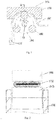
- An elastomeric-hose-compressing part G for a power head of a peristaltic pump comprises a surface 1 for compressing the elastomeric hose having an arcuate shape along its length direction (the left-right direction in Fig. 3 ), and the surface 1 for compressing the elastomeric hose may be fit with a roller assembly 2 of the pump head to compress the elastomeric hose 3 to thereby pump liquid.
- the surface 1 for compressing the elastomeric hose may be a continuous surface, or formed by a plurality of surfaces sequentially arranged along the length direction.
- the arcuate surface 1 for compressing the elastomeric hose may be a smooth surface or an approximately smooth surface formed by continuous straight-line segments.
- flanges 4 are oppositely provided on two side edges of the surface 1 for compressing the elastomeric hose in the width direction (the left-right direction in Fig. 4 ) of the elastomeric-hose-compressing part G, wherein the width direction of the elastomeric-hose-compressing part G is vertical to the length direction; the height f of the flange 4 is preferably not less than the elastomeric hose wall thickness 3; a ratio of the height h of the flange 4 to the width d of the flange 4 in the width direction of the elastomeric-hose-compressing part G is preferably in a range of 2 ⁇ d/h ⁇ 1/3.
- the width of the surface 1 for compressing the elastomeric hose in the width direction of the elastomeric-hose-compressing part G is larger than or equal to half of outer perimeter of cross section of the elastic hose.
- the surface 1 for compressing the elastomeric hose may be fitted with the roller assembly 2 to limit an elastomeric hose between the surface 1 for compressing the elastomeric hose and the rollers 5 of the roller assembly 2.
- the flange 4 comprises an inner sidewall 41, a top wall 42, and an outer sidewall 43, wherein the inner sidewall 41 and the surface 1 for compressing the elastomeric hose are intersected at a first edge D of the flange 4, the inner sidewall 41 and the top wall 42 are intersected at a second edge C of the flange 4, and the outer sidewall 43 and the top wall 42 are intersected at a third edge B of the flange 4.
- the top wall 42 is formed substantially obliquely between the outer sidewall 43 and the inner sidewall 42, the top wall 42 having an arc shape which is convex relative to the surface 1 for compressing the elastomeric hose, and the portion of the top wall 42 adjacent to the outer sidewall 43 is higher than the portion of the top wall adjacent to the inner sidewall, i.e., the third edge B of the flange 4 has the highest height (which is also the height h of the flange 4).
- a ratio of the height h of the flange 4 to the width d of the flange 4 in the width direction of the elastomeric-hose-compressing part G is in a range of 2 ⁇ d/h ⁇ 1/3.
- the width of the top wall 42 (i.e., the distance from the second edge C of the flange 4 to the outer sidewall 43 in Fig. 4 ) is larger than the elastomeric hose wall thickness.
- a joining surface with smooth transition between the inner sidewall 41 and the surface 1 for compressing the elastomeric hose is provided a joining surface with smooth transition, and between the inner sidewall 41 and the top wall 42 is provided a joining surface with smooth transition; a section of the inner sidewall 41 has a recessed arc shape.
- the curvature radius of the inner sidewall 41 on the arc section is not less than 1 times the elastomeric hose wall thickness.
- the section of the inner sidewall 41 is of an arc shape of not more than 1/4 circumference; the radius of the arc is 1.2-2.5 times the elastomeric hose wall thickness; the inner sidewall 41 is tangent with the surface 51 for compressing the elastomeric hose; therefore, during operation of the peristaltic pump, if the elastomeric hose offsets towards one side, the arc-shape inner sidewall 41 can envelop the elastomeric hose better so as to block offset of the elastomeric hose, thereby reducing abrasion to the elastomeric hose.
- the flange 4 has an inner sidewall 44 and an outer sidewall 45, the inner sidewall 44 being obliquely disposed between the top end of the outer sidewall 45 and the surface 1 for compressing the elastomeric hose.
- the inner sidewall 44 is of a plane shape; alternatively, the section of the inner sidewall 44 is of a recessed arc shape.
- the curvature radius of the inner sidewall 44 on the arc section is not less than 1 times the elastomeric hose wall thickness.
- a ratio of the height h of the flange 4 to the width d of the flange 4 in the width direction of the elastomeric-hose-compressing part G is in a range of 2 ⁇ d/h ⁇ 1/2.
- the section of the inner sidewall 44 is of an arc shape of not more than 1/4 circumference, wherein the radius of the arc being 1.2-2.5 times the elastomeric hose wall thickness, and the inner sidewall 44 is tangent with the surface 1 for compressing the elastomeric hose.
- the arc-shape inner sidewall 44 can envelop the elastomeric hose better so as to block offset of the elastomeric hose, thereby reducing abrasion to the elastomeric hose.
- an embodiment of the present disclosure further provides a cartridge for a pump head of a peristaltic pump.
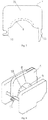
- the cartridge comprises: a cartridge body 7, wherein the cartridge body 7 has a shape, two sides of which are each provided with a snap-fitting part 71, 72; at a lower side of a transverse beam 73 of the cartridge body 7 is provided the elastomeric-hose-compressing part G as described above; and the cartridge body 7 is detachably mounted to the pump head via the snap-fitting parts 71, 72 disposed at the two sides.
- the detachable cartridge further comprises a tubing-compressing arcuate plate 8 that is mounted at the lower side of the transverse beam 73 of the cartridge body 7; the tubing-compressing arcuate plate 8 is provided with the elastomeric-hose-compressing part as described above, wherein the surface 1 for compressing the elastomeric hose may be fit with the roller assembly 9 so as to limit the elastomeric hose between the surface for compressing the elastomeric hose and the rollers 10 of the roller assembly of the peristaltic pump.
- An embodiment of the present disclosure further provides a roller assembly 2 for a pump head of a peristaltic pump.
- a roller assembly 2 for a pump head of a peristaltic pump.
- the rollers 5 are arranged on the roller assembly 2 via a rotary shaft; the axial direction of the rollers 5 is parallel to the axial direction of the roller assembly 2; the rollers 5 rotate independently relative to the roller assembly 2; annular flanges 4 which are convex radially along the rollers 5 are oppositely provided on two axial ends of the rollers 5, and surfaces of the rollers 5 between the annular flanges 4 oppositely provided on the two axial ends of the rollers 5 form a surface 51 for compressing the elastomeric hose.
- the height h of the flange 4 is preferably not less than the wall thickness of an elastomeric hose 3, and/or the width of the surface 51 for compressing the elastomeric hose along the axial direction of the roller assembly is larger than or equal to half of the outer wall perimeter of the elastomeric hose.
- the flange 4 comprises an inner sidewall 41, a top wall 42, and an outer sidewall 43, wherein the inner sidewall 41 and the surface 51 for compressing the elastomeric hose are intersected at a first edge D of the flange 4, the inner sidewall 41 and the top wall 42 are intersected at a second edge C of the flange 4, and the outer sidewall 43 and the top wall 42 are intersected at a third edge B of the flange 4.
- the top wall 42 is formed substantially obliquely between the outer sidewall 43 and the inner sidewall 41, the top wall 42 having an arc shape which is convex relative to the surface 51 for compressing the elastomeric hose, and the portion of the top wall 42 adjacent to the outer sidewall 43 being higher than the portion of the top wall 42 adjacent to the inner sidewall 41.
- the width of the top wall 42 along the axial direction of the roller assembly is preferably larger than the elastomeric hose wall thickness.
- a joining surface with smooth transition between the inner sidewall 41 and the top wall 42 is provided a joining surface with a smooth transition, and/or, a section of the inner sidewall 41 has a recessed arc shape.
- the curvature radius of the inner sidewall 41 on the arc section is not less than 1 times the elastomeric hose wall thickness.
- the section of the inner sidewall 41 is of an arc shape of not more than 1/4 circumference, the radius of the arc is 1.2-2.5 times the elastomeric hose wall thickness, and the inner sidewall 41 is tangent with the surface 51 for compressing the elastomeric hose.
- a ratio of the height h of the flange 4 to the width d of the flange 4 along the axial direction of the roller assembly is in a range of 2 ⁇ d/h ⁇ 1/3.
- the flange 4 has an inner sidewall 44 and an outer sidewall 45, the inner sidewall 44 being obliquely provided between the top end of the outer sidewall 45 and the surface 51 for compressing the elastomeric hose, the inner sidewall 44 being of a plane shape, or a section of the inner sidewall 44 being of a recessed arc shape.
- the curvature radius of the inner sidewall 44 on the arc section is not less than 1 times the elastomeric hose wall thickness.
- the section of the inner sidewall 44 is of an arc shape of not more than 1/4 circumference, the radius of the arc is 1.2-2.5 times the elastomeric hose wall thickness, and the inner sidewall 44 is tangent with the surface 51 for compressing the elastomeric hose. And/or, a ratio of the height h of the flange 4 to the width d of the flange 4 along the axial direction of the roller assembly is in a range of 2 ⁇ d/h ⁇ 1/2.
- An embodiment of the present disclosure further provides a pump head for a peristaltic pump, comprising the elastomeric-hose-compressing part as described above and/or the roller assembly as described above.
- a peristaltic pump using the elastomeric-hose-compressing part as disclosed in the embodiments the present disclosure a peristaltic pump using roller assembly as disclosed in the embodiments of the present disclosure, and a prior peristaltic pump
- #1 represents the prior peristaltic pump comprising a hose-compressing block 106 with a planar compressing surface and rollers 105 with column-shaped rolls as shown in Fig. 2
- #2 represents a peristaltic pump with the roller assembly shown in Figs. 10 and 11 according to the embodiments of the present disclosure
- #3 represents a peristaltic pump with the elastomeric-hose-compressing part G shown in Figs.
- the compressing surfaces of the #1, #2, and #3 peristaltic pumps have a same width; the liquid as conveyed is water, and the elastomeric hose is a silica gel tube with a 6.4mm inner diameter and a 9.6mm outer diameter.
- the peristaltic pumps under testing have three rollers; under the operating condition of 600 revolutions /minute, the average normal operating durations of respective peristaltic pumps are shown in the table below.
- S/N Average Normal Operating Duration (Hour) #1 20 hours #2 80 hours #3 100 hours
Landscapes
- Engineering & Computer Science (AREA)
- Mechanical Engineering (AREA)
- General Engineering & Computer Science (AREA)
- Reciprocating Pumps (AREA)
Applications Claiming Priority (2)
| Application Number | Priority Date | Filing Date | Title |
|---|---|---|---|
| CN201822203295.9U CN209370024U (zh) | 2018-12-26 | 2018-12-26 | 蠕动泵泵头弹性软管挤压部件、卡片、滚轮及蠕动泵泵头 |
| CN201811605118.1A CN110360086B (zh) | 2018-12-26 | 2018-12-26 | 蠕动泵泵头弹性软管挤压部件、卡片、滚轮及蠕动泵泵头 |
Publications (2)
| Publication Number | Publication Date |
|---|---|
| EP3674549A1 true EP3674549A1 (de) | 2020-07-01 |
| EP3674549B1 EP3674549B1 (de) | 2021-09-08 |
Family
ID=68699249
Family Applications (1)
| Application Number | Title | Priority Date | Filing Date |
|---|---|---|---|
| EP19211689.5A Active EP3674549B1 (de) | 2018-12-26 | 2019-11-27 | Aufspannplatte, kartusche und rolleneinheit für eine schlauchpumpe |
Country Status (2)
| Country | Link |
|---|---|
| US (2) | US11319945B2 (de) |
| EP (1) | EP3674549B1 (de) |
Families Citing this family (4)
| Publication number | Priority date | Publication date | Assignee | Title |
|---|---|---|---|---|
| CN112303281B (zh) * | 2020-09-14 | 2022-11-18 | 湖南明康中锦医疗科技发展有限公司 | 一种多并控制阀机构及医疗设备 |
| CN115628206B (zh) * | 2022-09-27 | 2023-07-25 | 深圳华星恒泰泵阀有限公司 | 一种便于管道限位的多组连接型蠕动泵 |
| CN115573947A (zh) * | 2022-09-30 | 2023-01-06 | 南京拓攻自动驾驶技术研究院有限公司 | 一种水泵、喷洒系统及植保无人机 |
| CN116066335A (zh) * | 2023-02-10 | 2023-05-05 | 厦门坤锦电子科技有限公司 | 一种流量控制的长寿命蠕动泵及其泵腔壳体制作工艺 |
Citations (6)
| Publication number | Priority date | Publication date | Assignee | Title |
|---|---|---|---|---|
| CH562402A5 (de) * | 1974-07-03 | 1975-05-30 | Asf Gmbh | |
| US5533878A (en) * | 1994-05-11 | 1996-07-09 | Daiichi Techno Co., Ltd. | Squeeze type pump |
| US5915932A (en) * | 1990-02-02 | 1999-06-29 | Isco, Inc. | Peristaltic pump having a roller support |
| WO2014105755A1 (en) * | 2012-12-24 | 2014-07-03 | Fresenius Medical Care Holdings, Inc. | Portable dialysis machine with improved reservoir heating system |
| WO2017129193A1 (en) * | 2016-01-25 | 2017-08-03 | Fluisense Aps | Micro dosage peristaltic pump for micro dosage of fluid |
| US20180230988A1 (en) * | 2017-02-16 | 2018-08-16 | Biosense Webster (Israel) Ltd. | Peristaltic pump with reduced triboelectric effects |
Family Cites Families (6)
| Publication number | Priority date | Publication date | Assignee | Title |
|---|---|---|---|---|
| US2982225A (en) * | 1959-01-23 | 1961-05-02 | Ronald E Thompson | Rotary pump of tube-compression type |
| US3335670A (en) * | 1965-01-25 | 1967-08-15 | Milton Roy Co | Steady flow metering pump |
| US3567345A (en) * | 1969-02-10 | 1971-03-02 | Shamban & Co W S | Peristaltic pump |
| US4518327A (en) * | 1981-11-25 | 1985-05-21 | Hackman Charles Henry | Rotary peristaltic pump |
| US4586882A (en) * | 1984-12-06 | 1986-05-06 | Baxter Travenol Laboratories, Inc. | Tubing occluder pump |
| DE3840259A1 (de) * | 1988-11-30 | 1990-05-31 | Amazonen Werke Dreyer H | Schlauchpumpe |
-
2019
- 2019-11-27 EP EP19211689.5A patent/EP3674549B1/de active Active
- 2019-12-06 US US16/706,240 patent/US11319945B2/en active Active
-
2022
- 2022-04-01 US US17/657,684 patent/US11585338B2/en active Active
Patent Citations (6)
| Publication number | Priority date | Publication date | Assignee | Title |
|---|---|---|---|---|
| CH562402A5 (de) * | 1974-07-03 | 1975-05-30 | Asf Gmbh | |
| US5915932A (en) * | 1990-02-02 | 1999-06-29 | Isco, Inc. | Peristaltic pump having a roller support |
| US5533878A (en) * | 1994-05-11 | 1996-07-09 | Daiichi Techno Co., Ltd. | Squeeze type pump |
| WO2014105755A1 (en) * | 2012-12-24 | 2014-07-03 | Fresenius Medical Care Holdings, Inc. | Portable dialysis machine with improved reservoir heating system |
| WO2017129193A1 (en) * | 2016-01-25 | 2017-08-03 | Fluisense Aps | Micro dosage peristaltic pump for micro dosage of fluid |
| US20180230988A1 (en) * | 2017-02-16 | 2018-08-16 | Biosense Webster (Israel) Ltd. | Peristaltic pump with reduced triboelectric effects |
Also Published As
| Publication number | Publication date |
|---|---|
| EP3674549B1 (de) | 2021-09-08 |
| US11585338B2 (en) | 2023-02-21 |
| US20200208625A1 (en) | 2020-07-02 |
| US11319945B2 (en) | 2022-05-03 |
| US20220220956A1 (en) | 2022-07-14 |
Similar Documents
| Publication | Publication Date | Title |
|---|---|---|
| US11585338B2 (en) | Elastomeric-hose-compressing part, cartridge, and roller assembly for pump head of a peristaltic pump | |
| EP3655654B1 (de) | Verdrängungspumpe mit rotierender membran | |
| CN100590041C (zh) | 一种螺旋叶片支承装置 | |
| KR20140066732A (ko) | 압연 스탠드 롤 네크 시일 | |
| CN110360086B (zh) | 蠕动泵泵头弹性软管挤压部件、卡片、滚轮及蠕动泵泵头 | |
| CN209370024U (zh) | 蠕动泵泵头弹性软管挤压部件、卡片、滚轮及蠕动泵泵头 | |
| US20090295096A1 (en) | Cartridge and related methods | |
| WO2024022295A1 (zh) | 涡旋式压缩机及制冷设备 | |
| CN110486473A (zh) | 一种新型旋转轴唇形密封圈 | |
| GB2430012A (en) | Pump Rotor And Shaft Connection | |
| US4709629A (en) | Roll with pressure chamber for detection control | |
| EP3655655B1 (de) | Verdrängungspumpe mit rotierender membran | |
| CN209743574U (zh) | 一种波齿复合垫片 | |
| CN218625421U (zh) | 一种旋转密封圈 | |
| CN210050299U (zh) | 带抛污槽的密封装置 | |
| CN107191377A (zh) | 旋转式压缩机 | |
| CN212645314U (zh) | 一种防漏油回转窑托轮密封机构 | |
| CN217328456U (zh) | 剖分式机械密封 | |
| CN223019408U (zh) | 双侧密封油封 | |
| CN109751278B (zh) | 火电厂纯凝湿冷机组低压水泵机械密封的方法及装置 | |
| CN107461332B (zh) | 一种油气混输泵 | |
| CN223024220U (zh) | 一种水泵电机静密封结构 | |
| CN214734785U (zh) | 立体旋转式网状接触体连接盘 | |
| CN222185760U (zh) | 一种新型密封圈 | |
| CN218717473U (zh) | 涡旋压缩机动静盘涡旋垫片浮动装置 |
Legal Events
| Date | Code | Title | Description |
|---|---|---|---|
| PUAI | Public reference made under article 153(3) epc to a published international application that has entered the european phase |
Free format text: ORIGINAL CODE: 0009012 |
|
| STAA | Information on the status of an ep patent application or granted ep patent |
Free format text: STATUS: THE APPLICATION HAS BEEN PUBLISHED |
|
| AK | Designated contracting states |
Kind code of ref document: A1 Designated state(s): AL AT BE BG CH CY CZ DE DK EE ES FI FR GB GR HR HU IE IS IT LI LT LU LV MC MK MT NL NO PL PT RO RS SE SI SK SM TR |
|
| AX | Request for extension of the european patent |
Extension state: BA ME |
|
| STAA | Information on the status of an ep patent application or granted ep patent |
Free format text: STATUS: REQUEST FOR EXAMINATION WAS MADE |
|
| 17P | Request for examination filed |
Effective date: 20201231 |
|
| RBV | Designated contracting states (corrected) |
Designated state(s): AL AT BE BG CH CY CZ DE DK EE ES FI FR GB GR HR HU IE IS IT LI LT LU LV MC MK MT NL NO PL PT RO RS SE SI SK SM TR |
|
| GRAP | Despatch of communication of intention to grant a patent |
Free format text: ORIGINAL CODE: EPIDOSNIGR1 |
|
| STAA | Information on the status of an ep patent application or granted ep patent |
Free format text: STATUS: GRANT OF PATENT IS INTENDED |
|
| INTG | Intention to grant announced |
Effective date: 20210616 |
|
| GRAS | Grant fee paid |
Free format text: ORIGINAL CODE: EPIDOSNIGR3 |
|
| GRAA | (expected) grant |
Free format text: ORIGINAL CODE: 0009210 |
|
| STAA | Information on the status of an ep patent application or granted ep patent |
Free format text: STATUS: THE PATENT HAS BEEN GRANTED |
|
| AK | Designated contracting states |
Kind code of ref document: B1 Designated state(s): AL AT BE BG CH CY CZ DE DK EE ES FI FR GB GR HR HU IE IS IT LI LT LU LV MC MK MT NL NO PL PT RO RS SE SI SK SM TR |
|
| REG | Reference to a national code |
Ref country code: GB Ref legal event code: FG4D |
|
| REG | Reference to a national code |
Ref country code: CH Ref legal event code: EP Ref country code: AT Ref legal event code: REF Ref document number: 1428822 Country of ref document: AT Kind code of ref document: T Effective date: 20210915 |
|
| REG | Reference to a national code |
Ref country code: IE Ref legal event code: FG4D |
|
| REG | Reference to a national code |
Ref country code: DE Ref legal event code: R096 Ref document number: 602019007542 Country of ref document: DE |
|
| REG | Reference to a national code |
Ref country code: LT Ref legal event code: MG9D |
|
| REG | Reference to a national code |
Ref country code: NL Ref legal event code: MP Effective date: 20210908 |
|
| PG25 | Lapsed in a contracting state [announced via postgrant information from national office to epo] |
Ref country code: SE Free format text: LAPSE BECAUSE OF FAILURE TO SUBMIT A TRANSLATION OF THE DESCRIPTION OR TO PAY THE FEE WITHIN THE PRESCRIBED TIME-LIMIT Effective date: 20210908 Ref country code: RS Free format text: LAPSE BECAUSE OF FAILURE TO SUBMIT A TRANSLATION OF THE DESCRIPTION OR TO PAY THE FEE WITHIN THE PRESCRIBED TIME-LIMIT Effective date: 20210908 Ref country code: ES Free format text: LAPSE BECAUSE OF FAILURE TO SUBMIT A TRANSLATION OF THE DESCRIPTION OR TO PAY THE FEE WITHIN THE PRESCRIBED TIME-LIMIT Effective date: 20210908 Ref country code: BG Free format text: LAPSE BECAUSE OF FAILURE TO SUBMIT A TRANSLATION OF THE DESCRIPTION OR TO PAY THE FEE WITHIN THE PRESCRIBED TIME-LIMIT Effective date: 20211208 Ref country code: LT Free format text: LAPSE BECAUSE OF FAILURE TO SUBMIT A TRANSLATION OF THE DESCRIPTION OR TO PAY THE FEE WITHIN THE PRESCRIBED TIME-LIMIT Effective date: 20210908 Ref country code: NO Free format text: LAPSE BECAUSE OF FAILURE TO SUBMIT A TRANSLATION OF THE DESCRIPTION OR TO PAY THE FEE WITHIN THE PRESCRIBED TIME-LIMIT Effective date: 20211208 Ref country code: HR Free format text: LAPSE BECAUSE OF FAILURE TO SUBMIT A TRANSLATION OF THE DESCRIPTION OR TO PAY THE FEE WITHIN THE PRESCRIBED TIME-LIMIT Effective date: 20210908 Ref country code: FI Free format text: LAPSE BECAUSE OF FAILURE TO SUBMIT A TRANSLATION OF THE DESCRIPTION OR TO PAY THE FEE WITHIN THE PRESCRIBED TIME-LIMIT Effective date: 20210908 |
|
| REG | Reference to a national code |
Ref country code: AT Ref legal event code: MK05 Ref document number: 1428822 Country of ref document: AT Kind code of ref document: T Effective date: 20210908 |
|
| PG25 | Lapsed in a contracting state [announced via postgrant information from national office to epo] |
Ref country code: LV Free format text: LAPSE BECAUSE OF FAILURE TO SUBMIT A TRANSLATION OF THE DESCRIPTION OR TO PAY THE FEE WITHIN THE PRESCRIBED TIME-LIMIT Effective date: 20210908 Ref country code: GR Free format text: LAPSE BECAUSE OF FAILURE TO SUBMIT A TRANSLATION OF THE DESCRIPTION OR TO PAY THE FEE WITHIN THE PRESCRIBED TIME-LIMIT Effective date: 20211209 |
|
| PG25 | Lapsed in a contracting state [announced via postgrant information from national office to epo] |
Ref country code: AT Free format text: LAPSE BECAUSE OF FAILURE TO SUBMIT A TRANSLATION OF THE DESCRIPTION OR TO PAY THE FEE WITHIN THE PRESCRIBED TIME-LIMIT Effective date: 20210908 |
|
| PG25 | Lapsed in a contracting state [announced via postgrant information from national office to epo] |
Ref country code: IS Free format text: LAPSE BECAUSE OF FAILURE TO SUBMIT A TRANSLATION OF THE DESCRIPTION OR TO PAY THE FEE WITHIN THE PRESCRIBED TIME-LIMIT Effective date: 20220108 Ref country code: SM Free format text: LAPSE BECAUSE OF FAILURE TO SUBMIT A TRANSLATION OF THE DESCRIPTION OR TO PAY THE FEE WITHIN THE PRESCRIBED TIME-LIMIT Effective date: 20210908 Ref country code: SK Free format text: LAPSE BECAUSE OF FAILURE TO SUBMIT A TRANSLATION OF THE DESCRIPTION OR TO PAY THE FEE WITHIN THE PRESCRIBED TIME-LIMIT Effective date: 20210908 Ref country code: RO Free format text: LAPSE BECAUSE OF FAILURE TO SUBMIT A TRANSLATION OF THE DESCRIPTION OR TO PAY THE FEE WITHIN THE PRESCRIBED TIME-LIMIT Effective date: 20210908 Ref country code: PT Free format text: LAPSE BECAUSE OF FAILURE TO SUBMIT A TRANSLATION OF THE DESCRIPTION OR TO PAY THE FEE WITHIN THE PRESCRIBED TIME-LIMIT Effective date: 20220110 Ref country code: PL Free format text: LAPSE BECAUSE OF FAILURE TO SUBMIT A TRANSLATION OF THE DESCRIPTION OR TO PAY THE FEE WITHIN THE PRESCRIBED TIME-LIMIT Effective date: 20210908 Ref country code: NL Free format text: LAPSE BECAUSE OF FAILURE TO SUBMIT A TRANSLATION OF THE DESCRIPTION OR TO PAY THE FEE WITHIN THE PRESCRIBED TIME-LIMIT Effective date: 20210908 Ref country code: EE Free format text: LAPSE BECAUSE OF FAILURE TO SUBMIT A TRANSLATION OF THE DESCRIPTION OR TO PAY THE FEE WITHIN THE PRESCRIBED TIME-LIMIT Effective date: 20210908 Ref country code: CZ Free format text: LAPSE BECAUSE OF FAILURE TO SUBMIT A TRANSLATION OF THE DESCRIPTION OR TO PAY THE FEE WITHIN THE PRESCRIBED TIME-LIMIT Effective date: 20210908 Ref country code: AL Free format text: LAPSE BECAUSE OF FAILURE TO SUBMIT A TRANSLATION OF THE DESCRIPTION OR TO PAY THE FEE WITHIN THE PRESCRIBED TIME-LIMIT Effective date: 20210908 |
|
| REG | Reference to a national code |
Ref country code: DE Ref legal event code: R097 Ref document number: 602019007542 Country of ref document: DE |
|
| PG25 | Lapsed in a contracting state [announced via postgrant information from national office to epo] |
Ref country code: MC Free format text: LAPSE BECAUSE OF FAILURE TO SUBMIT A TRANSLATION OF THE DESCRIPTION OR TO PAY THE FEE WITHIN THE PRESCRIBED TIME-LIMIT Effective date: 20210908 |
|
| PLBE | No opposition filed within time limit |
Free format text: ORIGINAL CODE: 0009261 |
|
| STAA | Information on the status of an ep patent application or granted ep patent |
Free format text: STATUS: NO OPPOSITION FILED WITHIN TIME LIMIT |
|
| PG25 | Lapsed in a contracting state [announced via postgrant information from national office to epo] |
Ref country code: LU Free format text: LAPSE BECAUSE OF NON-PAYMENT OF DUE FEES Effective date: 20211127 Ref country code: DK Free format text: LAPSE BECAUSE OF FAILURE TO SUBMIT A TRANSLATION OF THE DESCRIPTION OR TO PAY THE FEE WITHIN THE PRESCRIBED TIME-LIMIT Effective date: 20210908 Ref country code: BE Free format text: LAPSE BECAUSE OF NON-PAYMENT OF DUE FEES Effective date: 20211130 |
|
| REG | Reference to a national code |
Ref country code: BE Ref legal event code: MM Effective date: 20211130 |
|
| 26N | No opposition filed |
Effective date: 20220609 |
|
| PG25 | Lapsed in a contracting state [announced via postgrant information from national office to epo] |
Ref country code: SI Free format text: LAPSE BECAUSE OF FAILURE TO SUBMIT A TRANSLATION OF THE DESCRIPTION OR TO PAY THE FEE WITHIN THE PRESCRIBED TIME-LIMIT Effective date: 20210908 |
|
| PG25 | Lapsed in a contracting state [announced via postgrant information from national office to epo] |
Ref country code: IE Free format text: LAPSE BECAUSE OF NON-PAYMENT OF DUE FEES Effective date: 20211127 |
|
| PG25 | Lapsed in a contracting state [announced via postgrant information from national office to epo] |
Ref country code: IT Free format text: LAPSE BECAUSE OF FAILURE TO SUBMIT A TRANSLATION OF THE DESCRIPTION OR TO PAY THE FEE WITHIN THE PRESCRIBED TIME-LIMIT Effective date: 20210908 |
|
| PG25 | Lapsed in a contracting state [announced via postgrant information from national office to epo] |
Ref country code: CY Free format text: LAPSE BECAUSE OF FAILURE TO SUBMIT A TRANSLATION OF THE DESCRIPTION OR TO PAY THE FEE WITHIN THE PRESCRIBED TIME-LIMIT Effective date: 20210908 |
|
| REG | Reference to a national code |
Ref country code: CH Ref legal event code: PL |
|
| PG25 | Lapsed in a contracting state [announced via postgrant information from national office to epo] |
Ref country code: LI Free format text: LAPSE BECAUSE OF NON-PAYMENT OF DUE FEES Effective date: 20221130 Ref country code: HU Free format text: LAPSE BECAUSE OF FAILURE TO SUBMIT A TRANSLATION OF THE DESCRIPTION OR TO PAY THE FEE WITHIN THE PRESCRIBED TIME-LIMIT; INVALID AB INITIO Effective date: 20191127 Ref country code: CH Free format text: LAPSE BECAUSE OF NON-PAYMENT OF DUE FEES Effective date: 20221130 |
|
| PG25 | Lapsed in a contracting state [announced via postgrant information from national office to epo] |
Ref country code: MK Free format text: LAPSE BECAUSE OF FAILURE TO SUBMIT A TRANSLATION OF THE DESCRIPTION OR TO PAY THE FEE WITHIN THE PRESCRIBED TIME-LIMIT Effective date: 20210908 |
|
| PG25 | Lapsed in a contracting state [announced via postgrant information from national office to epo] |
Ref country code: TR Free format text: LAPSE BECAUSE OF FAILURE TO SUBMIT A TRANSLATION OF THE DESCRIPTION OR TO PAY THE FEE WITHIN THE PRESCRIBED TIME-LIMIT Effective date: 20210908 |
|
| PG25 | Lapsed in a contracting state [announced via postgrant information from national office to epo] |
Ref country code: MT Free format text: LAPSE BECAUSE OF FAILURE TO SUBMIT A TRANSLATION OF THE DESCRIPTION OR TO PAY THE FEE WITHIN THE PRESCRIBED TIME-LIMIT Effective date: 20210908 |
|
| REG | Reference to a national code |
Ref country code: DE Ref legal event code: R081 Ref document number: 602019007542 Country of ref document: DE Owner name: LEAD FLUID (BAODING) INTELLIGENT EQUIPMENT MAN, CN Free format text: FORMER OWNER: BAODING LEAD FLUID TECHNOLOGY CO., LTD., BAODING, HEBEI, CN |
|
| REG | Reference to a national code |
Ref country code: GB Ref legal event code: 732E Free format text: REGISTERED BETWEEN 20250424 AND 20250430 |
|
| PGFP | Annual fee paid to national office [announced via postgrant information from national office to epo] |
Ref country code: DE Payment date: 20251117 Year of fee payment: 7 |
|
| PGFP | Annual fee paid to national office [announced via postgrant information from national office to epo] |
Ref country code: GB Payment date: 20251126 Year of fee payment: 7 |
|
| PGFP | Annual fee paid to national office [announced via postgrant information from national office to epo] |
Ref country code: FR Payment date: 20251127 Year of fee payment: 7 |