EP3674577A1 - Stellglied für elektromechanische trommelbremse mit erhöhter widerstandsfähigkeit - Google Patents
Stellglied für elektromechanische trommelbremse mit erhöhter widerstandsfähigkeit Download PDFInfo
- Publication number
- EP3674577A1 EP3674577A1 EP19217648.5A EP19217648A EP3674577A1 EP 3674577 A1 EP3674577 A1 EP 3674577A1 EP 19217648 A EP19217648 A EP 19217648A EP 3674577 A1 EP3674577 A1 EP 3674577A1
- Authority
- EP
- European Patent Office
- Prior art keywords
- actuator
- elastically deformable
- drive system
- housing
- longitudinal
- Prior art date
- Legal status (The legal status is an assumption and is not a legal conclusion. Google has not performed a legal analysis and makes no representation as to the accuracy of the status listed.)
- Granted
Links
Images


Classifications
-
- F—MECHANICAL ENGINEERING; LIGHTING; HEATING; WEAPONS; BLASTING
- F16—ENGINEERING ELEMENTS AND UNITS; GENERAL MEASURES FOR PRODUCING AND MAINTAINING EFFECTIVE FUNCTIONING OF MACHINES OR INSTALLATIONS; THERMAL INSULATION IN GENERAL
- F16D—COUPLINGS FOR TRANSMITTING ROTATION; CLUTCHES; BRAKES
- F16D51/00—Brakes with outwardly-movable braking members co-operating with the inner surface of a drum or the like
- F16D51/16—Brakes with outwardly-movable braking members co-operating with the inner surface of a drum or the like shaped as brake-shoes pivoted on a fixed or nearly-fixed axis
- F16D51/18—Brakes with outwardly-movable braking members co-operating with the inner surface of a drum or the like shaped as brake-shoes pivoted on a fixed or nearly-fixed axis with two brake-shoes
- F16D51/20—Brakes with outwardly-movable braking members co-operating with the inner surface of a drum or the like shaped as brake-shoes pivoted on a fixed or nearly-fixed axis with two brake-shoes extending in opposite directions from their pivots
- F16D51/22—Brakes with outwardly-movable braking members co-operating with the inner surface of a drum or the like shaped as brake-shoes pivoted on a fixed or nearly-fixed axis with two brake-shoes extending in opposite directions from their pivots mechanically actuated
-
- F—MECHANICAL ENGINEERING; LIGHTING; HEATING; WEAPONS; BLASTING
- F16—ENGINEERING ELEMENTS AND UNITS; GENERAL MEASURES FOR PRODUCING AND MAINTAINING EFFECTIVE FUNCTIONING OF MACHINES OR INSTALLATIONS; THERMAL INSULATION IN GENERAL
- F16D—COUPLINGS FOR TRANSMITTING ROTATION; CLUTCHES; BRAKES
- F16D51/00—Brakes with outwardly-movable braking members co-operating with the inner surface of a drum or the like
- F16D51/46—Self-tightening brakes with pivoted brake shoes, i.e. the braked member increases the braking action
- F16D51/48—Self-tightening brakes with pivoted brake shoes, i.e. the braked member increases the braking action with two linked or directly-interacting brake shoes
- F16D51/50—Self-tightening brakes with pivoted brake shoes, i.e. the braked member increases the braking action with two linked or directly-interacting brake shoes mechanically actuated
-
- F—MECHANICAL ENGINEERING; LIGHTING; HEATING; WEAPONS; BLASTING
- F16—ENGINEERING ELEMENTS AND UNITS; GENERAL MEASURES FOR PRODUCING AND MAINTAINING EFFECTIVE FUNCTIONING OF MACHINES OR INSTALLATIONS; THERMAL INSULATION IN GENERAL
- F16D—COUPLINGS FOR TRANSMITTING ROTATION; CLUTCHES; BRAKES
- F16D65/00—Parts or details
- F16D65/14—Actuating mechanisms for brakes; Means for initiating operation at a predetermined position
- F16D65/16—Actuating mechanisms for brakes; Means for initiating operation at a predetermined position arranged in or on the brake
- F16D65/22—Actuating mechanisms for brakes; Means for initiating operation at a predetermined position arranged in or on the brake adapted for pressing members apart, e.g. for drum brakes
Definitions
- the present invention relates to an actuator for an electromechanical drum brake having increased robustness.
- the service brake is provided by disc brakes and / or drum brakes.
- the parking or parking brake function intended to immobilize a stationary vehicle and the emergency brake function are generally obtained with the system providing the parking brake.
- the application of the parking brake can be obtained by pulling a lever arranged in the passenger compartment which is connected to a mechanism located in a drum brake or a disc brake, via a brake cable.
- the mechanism tends to spread the braking segments of the drum brakes to apply them against the drums.
- the pads are tightened on the brake disc.
- an actuator provided with an electric motor is arranged at least on each rear brake, and causes the brakes to be applied.
- the driver presses, for example, a button on the dashboard to activate the electric parking brake.
- Electric parking brake systems include direct current electric motors, the implementation of such motors being recommended for example by the German association of the automobile industry in its "VDA Recommendation”.
- the piston which is moved by the actuator and which comes to apply the brake pads against the brake disc.
- the actuator is for example disposed between the brake shoes and serves as a fixed point during the application of service braking via a wheel cylinder.
- the actuator is for example of the screw-nut type and spreads the segments.
- the actuator has two pistons which bear against the brake shoes. The displacement of the pistons away from each other causes the application of the segments against the drum.
- the pistons are configured to be mobile in translation and fixed in rotation.
- one of the pistons is formed by the screw which is blocked in rotation and the other piston is carried by the nut and is free to rotate relative to the latter.
- the nut is rotated by the electric motor, it moves in translation, causing the two pistons to separate from one another.
- Measuring the current and / or voltage at the terminals of the electric motor makes it possible to know the state of the brake applied. Indeed, when the brake is applied, since the nut is integral in translation with the second piston, a force is opposed to the displacement of the nut, which generates an increase in current and / or voltage across the terminals of the motor. activating the actuator. This consumption peak corresponds to a tight state of the parking brake.
- the contact information between the nut and the housing provides this information without requiring a specific additional sensor. We want to keep this information while avoiding brutal contact.
- an actuator for an electromechanical drum brake comprising a housing, two pistons each intended to apply a friction element against the drum secured to a wheel, the pistons being configured to move at least in translation .
- the actuator comprises a drive system arranged in an actuator housing, the drive system is activated by an electric motor, and sets in motion the pistons.
- the drive system includes elastic stop means configured to be interposed between the drive system and the actuator housing at the end of the brake release phase, when the brake is actually released.
- the control unit Since the force opposing the drive system gradually increases due to the elastic deformation of the stopper, this results in a progressive increase in the electric current, the control unit then has time to detect this variation in consumption of current and generate an order to stop the electric motor before contact between the enclosure and the housing.
- the brake release information is always available while creating a more robust actuator with an increased service life
- the elastic stop applies a force oriented transversely to the longitudinal axis.
- it is a longitudinal end of the preloaded elastic element which bears against the housing of the actuator.
- the number of parts of the actuator is unchanged.
- an additional elastic element is added, which makes it possible to have a stiffness at the level of contact with the housing, adjustable relative to the stiffness of the preloaded elastic element.
- the elastic stop comprises a piston mounted to slide, for example in the nut and comprising a longitudinal end in contact with a preloaded elastic element and another end intended to come into contact with the housing during brake release.
- the elastic element opposes the displacement of the piston, which ensures an increasing force opposing the displacement of the nut and a progressive increase in the consumption of current by the electric motor detectable by the control unit.
- an active elastic stop is introduced into the actuator beyond a certain brake release stroke, thus avoiding a sudden shock and allowing a progressive increase in the current consumed and offering a time lapse of a duration. sufficient for the control unit to stop the engine and avoid damage to the actuator.
- the present invention therefore relates to an electromechanical actuator for a drum brake, said drum brake comprising at least two friction members intended to come into contact with a drum integral in rotation with the wheel, said actuator being intended to apply said organs of friction against said drum, said actuator comprising a housing extending in a longitudinal direction, at least two pistons, each piston being intended to exert a force on a friction member to apply it against the drum, said pistons being slidably mounted in through passages of the housing along the longitudinal direction, the actuator also comprising a drive system mounted in the housing and intended to separate the pistons from one another during a braking phase and to bring them closer each other during a brake release phase, said drive system comprising a screw-nut assembly and at least one elastically deformable element only mounted preloaded between two moving parts in translation with respect to each other along the longitudinal direction, said system comprising first and second longitudinal end faces opposite each of a first and second longitudinal bottom of the housing.
- the drive system also includes interposition means arranged so as to be interposed between the drive system and the first longitudinal bottom of the housing, said interposition means being configured so that at the end of the brake release phase, they come into contact with the first longitudinal bottom of the housing and form an elastic stop with the first longitudinal bottom of the housing.
- the interposing means are arranged so as to be interposed between at least the first end face of the drive system and the first longitudinal bottom of the housing.
- the drive system comprises a nut, a screw and a third element, a sleeve integral in rotation and in translation with the nut and the third element, the elastically deformable element being mounted in reaction between the nut and the third element, and one of the pistons is carried by the nut and the other piston is carried by the third element.
- interposing means exert a force opposing the displacement of the drive system, said force being oriented substantially transversely to the longitudinal direction.
- the interposing means comprise a longitudinal end of an elastically deformable member projecting from the first end face of the drive system, and the first longitudinal bottom comprises a face parallel to the longitudinal direction against which the protruding longitudinal end of the elastically deformable member is intended to come into contact at the end of the braking phase.
- the first end face of the drive system may comprise a window extending angularly, said window being crossed by the longitudinal end of the elastically deformable member, and the window is delimited angularly by a first edge and a second edge , the elastically deformable member being oriented so that at the end of the braking phase, when the longitudinal end of the elastically deformable member is in contact with the face of the first longitudinal bottom, the longitudinal end of the deformable member elastically moves from the first edge to the second edge increasing the load of the elastically deformable member.
- the elastically deformable element is advantageously a helical spring and forms the elastically deformable member, distinct from the deformable element.
- the elastically deformable member is a second helical spring separate from the elastically deformable element and is mounted in a housing formed in the nut.
- the second helical spring is preferably immobilized in rotation in the nut.
- the interposing means (exert a force opposing the movement of the drive system, said force being oriented substantially in the longitudinal direction.
- the interposing means may comprise at least one pin projecting from the first end face of the drive system and mounted capable of sliding in said first face, said pin being mounted in reaction against a second elastically deformable member so that '' a restoring force is exerted against the pin towards the outside of the drive system.
- the second elastically deformable member is for example formed by the elastically deformable element.
- the present invention also relates to a drum brake comprising a drum, a plate, two segments, an actuator according to the invention, the actuator being fixed on the plate.
- the drum brake advantageously comprises a control unit comprising means for controlling the supply of the electric motor and means for measuring the electric consumption of the electric motor, said control means being configured to stop supplying the electric motor, when the power consumption exceeds a given value at least when the brake is released.
- the control unit is advantageously configured to stop the electric motor if a given value of current consumption is exceeded, at least when the brake is released.
- the actuator can be configured to apply at least one parking brake, and the brake can include another actuator to apply service braking.
- a "dual mode" drum brake 2 can be seen in an exemplary embodiment of the invention.
- the drum brake 1 comprises a drum (not shown) integral in movement with the wheel (not shown), a plate 2 of revolution of axis X equipped with a first and a second segment in an arc of circles 3 and 4 radially movable so that they can be pressed against the internal cylindrical face of a drum, not shown.
- the segments 3 and 4 each comprise a core 3a, 4a of flat sheet metal in the form of a portion of circular crown which carries a brake lining 3b, 4b, and are mounted diametrically opposite with their ends bearing both on a wheel cylinder 6 hydraulic and on a mechanical actuator 10 carried by the plate 2.
- These segments 3 and 4 are also biased towards each other by two return springs 8 and 9, and pressed against the plate 2 each by a spring called lateral.
- a wear take-up link 7 extends along the wheel cylinder 6 having a first end bearing on the core 3a of the first segment 3 and a second end bearing on the core 4a of the second segment 4 when the brake is at rest.
- the wheel cylinder 6 is intended to be actuated during use of the drum brake 1 according to a first operating mode called "simplex", which provides progressive braking particularly suitable for braking the vehicle in service. It includes a hydraulic chamber closed at its ends by two pistons which move away from each other when the hydraulic pressure increases and pushes the associated ends of segments 3 and 4.
- the mechanical actuator 10 ensures, for its part, the parking or parking and emergency braking by spreading the associated ends of the segments to ensure rapid and powerful locking of the vehicle wheels according to a so-called "duo-servo" operating mode, in particular when the wheel cylinder 6 is inactive.
- This actuator is driven by an electric motor 14.
- the wheel cylinder comprises two opposite pistons, which each actuate one of the segments 3, 4 by moving their two ends 3.1 apart, 4.1 opposite, that is to say those located on the same side of the axis of rotation X, here called “movable ends” and located at the top of the figure 3 .
- each segment is supported on the plate 2 by an anchoring element secured to the plate, and thus forming a stop for this segment.
- the anchoring element at least partially transmits the braking torque between segments and plate.
- the anchoring element of the two segments is produced by the actuator 10.
- the actuator 10 extends along an axis Y perpendicular to the axis X of the plate and parallel to the plate. It comprises a housing 12 fixed on plate 2 on the side of the first face.
- the housing 12 comprises a housing extending along the axis Y and opening at the two longitudinal ends of the housing 12.
- a drive assembly is housed in the housing 12.
- the drum brake also includes a drive device 14 for the actuator, fixed on the face of the plate opposite the face on the side of which the actuator 10 is mounted.
- the drive device is an electric motor which may or may not be associated with a reduction gear.
- a passage (not visible) is made through the plate 4 to allow the transmission of the drive from the drive device to the drive assembly of the actuator 10.
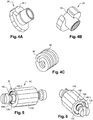
- the actuator comprises two pistons 28, 30 each intended to come into contact with a brake shoe.
- the actuator drive assembly is of the screw-nut type and forms a cartridge mounted in the actuator housing. It comprises a first element 24 provided with a thread and forming a screw, and the head of which forms one of the pistons 28, a second element 26 provided with a thread forming a nut and a third element 27 carrying the other piston 30 .
- the third element 27 is intended to move in rotation and in translation under the action of the electric motor.
- the other piston 30 is mounted integral in translation with the third element 27 on a rod-shaped longitudinal end of the third element 27 and free to rotate relative to the third element 27 about the longitudinal axis Y.
- the pistons 28, 30 are guided in translation directly by the walls of passages 32, 34 respectively formed in first and second longitudinal bottoms of the actuator housing.
- a sleeve 35 intended to transmit the rotation of the motor to the nut 26.
- the sleeve 35 is tubular in shape and is mounted around the nut 26 and the third element 27 forming a pusher.
- the third element is integral in rotation and in translation with the sleeve 35 and the nut 26 is integral in rotation with the sleeve 35.
- the sleeve has a polygonal cross section cooperating with an interior passage of cheese corresponding to externally toothed wheel 36 and driven by the electric motor.
- the sleeve 35 is crimped by a longitudinal end on an outer edge of a radial projection 38 of the third element and comprises at its other longitudinal end a flange 39 folded radially inwards, delimiting a passage for the piston 28 and forming a longitudinal stop for the nut 26.
- the outer contours of the cross section of the radial projection 38 of the third element 27 and the cross section of the nut 26 are polygonal, for example dodecagonal and cooperate with the sleeve 35 ensuring a rotational attachment between the sleeve 35, the third element 27 and the nut.
- the drive assembly also comprises an elastically deformable means 40 along the axis of the actuating movement, called elastic element, also called “spring pack” in English to provide the function of stabilizing the forces in the support chain.
- this elastic element 40 is a helical spring mounted preloaded between a bearing face 26.1 of the nut 26 and a face 38.1 of the radial projection 38 of the third element 27 opposite the bearing face of the nut 26
- the sleeve ensures the preload of the spring 40 by fixing the maximum longitudinal distance between the bearing face of the nut and the opposite face of the radial projection 38.
- this elastic element has a determined stiffness to provide a stroke making it possible to maintain or restore sufficient support of the segments against the drum in different circumstances or changes in situations.
- this elastic element is thus capable of storing, by compression in the actuation assembly during activation of the actuator while the device is in the first braking position, a sufficient amount of mechanical energy. to maintain or bring the device into the second braking position if the pressing of the brake cylinder 6 is interrupted after activation of the actuator 10 without needing to activate the actuator again.
- the actuator also comprises interposition means I1 intended to come to be interposed, at least temporarily, between a first longitudinal end face 42 of the drive system and a first longitudinal bottom 44 of the facing box and ensuring a damped contact between the drive system and the first longitudinal bottom 44.
- the interposition means I1 comprise a longitudinal end 46 of the spring 40 which projects from the longitudinal end face 42 of the drive system, and the first longitudinal bottom 44 comprises a portion 48 parallel to the longitudinal axis Y, against which abuts the protruding longitudinal end 46 of the spring at the end of the braking phase.
- the longitudinal end face 42 has an angular window 50 crossed by the longitudinal end 46 of the spring 40.
- the window is formed by two cutouts 52, 54 each formed in the flange 39 of the sleeve and in the nut 26, the two cutouts being at least partially aligned.
- the window 50 is delimited angularly by two edges 50.1, 50.2. In the absence of contact with the portion 48, the longitudinal end bears against an edge 50.1 of the window.
- the two edges 50.1, 50.2 form an angle sufficient to allow the control unit to detect the increase in current, and stop the motor before the longitudinal end of the spring comes to bear against the edge 50.2.
- the angle is between 10 ° and 30 °.
- the control unit sends an order to the motor to activate the actuator to apply the brake linings against the drum.
- the motor rotates in a first direction the sleeve 35 via the ring gear and possibly a reduction gear.
- the sleeve rotates the nut in a direction of unscrewing the screw, causing the displacement of the first and second pistons towards the outside of the housing, moving the brake linings towards the outside and applying them against the drum.
- the electric motor rotates the sleeve in a second direction, which rotates the nut in a screwing direction of the screw, which moves towards the inside of the case, the two pistons approach each other. Due to the return means, the linings are spaced from the drum.
- the longitudinal end face of the drive system approaches the first longitudinal bottom 44 of the housing.
- the spring 40 rotates with the sleeve 35, the nut 26 and the third part 27. Its longitudinal projecting end bears against the flange 50.1 of the window 50.
- the protruding longitudinal end of the spring comes into contact with the face 48 of the first bottom 44.
- the other edge 50.2 of the window is oriented so that, when the protruding longitudinal end of the spring is in contact with the face 48 and the sleeve and the nut are still driven in rotation, the longitudinal end of the spring approaches the edge 50.2.
- the direction of winding of the spring is such that, during this approximation, the turns come closer generating an elastic force opposing this approximation. This results in a damped contact between the drive system and the housing and not a sudden contact which takes place in the actuators of the prior art.
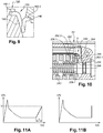
- this effort results in an increase in the current i consumed by the motor as shown in graph 11A.
- the elastic force opposing the approximation increases progressively, the current consumption therefore also increases progressively.
- the control unit detects this increase in current consumption, translates it as corresponding to a loose state of the drum brake and generates an order to stop the electric motor. For example, when the value of the current consumed exceeds a threshold value V, the control unit considers that the brake is released and that the motor can be stopped.
- the control unit has a certain time T to detect this increase and stop the motor.
- T For comparison on the figure 11B you can see the current variation in a prior art actuator when the drive system comes on directly in contact by one side with the housing. The contact is brutal and the increase in consumption is instantaneous, the control unit does not have time to stop the engine. The actuator can be damaged after several cycles.
- the actuator is very robust and has an extended service life.
- the inventors have determined that it can operate for approximately 250,000 cycles for a force moment of maximum value 2 N.m.
- the protruding longitudinal end of the spring is not mounted in a window but is folded back so that it is it which deforms when the portion 48 is pressed.
- the actuator A2 differs from the actuator A1 in that the interposition means I2 are not formed by a longitudinal end of the spring of the spring package, but by an end of a second elastically deformable element 156 which is received in a housing 158 of the nut 126 opening towards the first bottom 142 of the housing ( figure 8A ).
- the second elastic deformable element 156 is shown alone on the figure 8B . It comprises for example a single turn 160 and two ends 160.1, 160.2 folded relative to the direction of the turn. One end 160.1 is anchored in the bottom of the housing 158 of the nut preventing the turn from turning in the housing, and the other end 60.2 projects from the longitudinal end face 142 through a window 150 passing through the flange 139 of sleeve 135.
- This embodiment has the advantage of being able to choose the stiffness of the elastic stop independently of that of the spring package. It therefore offers greater freedom in the design of the actuator.
- the interposition means I3 comprise at least one pin 262 slidably mounted in a passage passing through the nut 226 extending in the longitudinal direction.
- the pin 262 has a first longitudinal end 262.1 projecting from the end face 242 of the drive system and facing the first bottom 244 of the housing, and a second longitudinal end 262.2 projecting from the bearing face 228.1 of the 'nut against which the spring 240 is supported.
- the second longitudinal end 262.2 is in abutment against the spring, more particularly against an end turn of the spring in abutment against the nut.
- the pin 262 comprises a head 264 intended to come into contact with the first bottom 244 of the housing.
- the head 264 has an annular projection 266 intended to bear against the face of the nut.
- the operation of the actuator is as follows.
- the parking brake application phase takes place in a similar way to that with actuator A1.
- the rim 240 of the sleeve has a window for the passage of the head 264. In the braking position, the flange 266 is detached from the nut under the action of the spring.
- the sliding of the pin 262 in the passage is sealed.
- a seal for example an O-ring 268, is mounted between the pin and the passage.
- pins are distributed in the nut ensuring uniform support between the drive system and the internal longitudinal end, for example three pins are arranged at 120 ° from each other are provided.
- the pin is mounted transversely and bears against a portion parallel to the longitudinal axis similar to the portion 48.
- an elastic return element can be implemented.
- the drive system comprises a second elastically deformable element mounted for example in the nut and only serving for the elastic stop, similarly to the actuator of the Figures 5 to 9 .
- a second elastically deformable element mounted for example in the nut and only serving for the elastic stop, similarly to the actuator of the Figures 5 to 9 .
- an assembly in the form of a cartridge comprising the pin and the spring is mounted in the nut.
- the pin (s) is or are mounted in the radial projection of the third element.
Landscapes
- Engineering & Computer Science (AREA)
- General Engineering & Computer Science (AREA)
- Mechanical Engineering (AREA)
- Braking Arrangements (AREA)
- Braking Systems And Boosters (AREA)
Applications Claiming Priority (1)
| Application Number | Priority Date | Filing Date | Title |
|---|---|---|---|
| FR1874241A FR3091323B1 (fr) | 2018-12-27 | 2018-12-27 | Actionneur pour frein a tambour electromecanique presentant une robustesse augmentee |
Publications (2)
| Publication Number | Publication Date |
|---|---|
| EP3674577A1 true EP3674577A1 (de) | 2020-07-01 |
| EP3674577B1 EP3674577B1 (de) | 2021-11-17 |
Family
ID=66776504
Family Applications (1)
| Application Number | Title | Priority Date | Filing Date |
|---|---|---|---|
| EP19217648.5A Active EP3674577B1 (de) | 2018-12-27 | 2019-12-18 | Stellglied für elektromechanische trommelbremse mit erhöhter widerstandsfähigkeit |
Country Status (2)
| Country | Link |
|---|---|
| EP (1) | EP3674577B1 (de) |
| FR (1) | FR3091323B1 (de) |
Citations (5)
| Publication number | Priority date | Publication date | Assignee | Title |
|---|---|---|---|---|
| DE19858642A1 (de) * | 1998-12-18 | 2000-06-21 | Volkswagen Ag | Getriebeähnlich ausgebildete Vorrichtung zur Betätigung der Bremsbacken |
| WO2005070736A2 (de) * | 2004-01-21 | 2005-08-04 | Continental Teves Ag & Co. Ohg | Elektromechanisch betätigbare feststellbremse |
| WO2015082205A2 (de) * | 2013-12-04 | 2015-06-11 | Continental Teves Ag & Co. Ohg | Elektromechanisch betätigbare trommelbremse |
| WO2015101611A2 (fr) * | 2013-12-30 | 2015-07-09 | Chassis Brakes International B.V. | Actionneur entraine par pignon a glissiere axiale, et frein a tambour et dispositif de freinage ainsi equipes |
| EP3089901A2 (de) * | 2013-12-30 | 2016-11-09 | Chassis Brakes International B.V. | Motorreduzierer mit planetengetriebe, trommel und scheibenbremse und bremsvorrichtung damit |
-
2018
- 2018-12-27 FR FR1874241A patent/FR3091323B1/fr not_active Expired - Fee Related
-
2019
- 2019-12-18 EP EP19217648.5A patent/EP3674577B1/de active Active
Patent Citations (5)
| Publication number | Priority date | Publication date | Assignee | Title |
|---|---|---|---|---|
| DE19858642A1 (de) * | 1998-12-18 | 2000-06-21 | Volkswagen Ag | Getriebeähnlich ausgebildete Vorrichtung zur Betätigung der Bremsbacken |
| WO2005070736A2 (de) * | 2004-01-21 | 2005-08-04 | Continental Teves Ag & Co. Ohg | Elektromechanisch betätigbare feststellbremse |
| WO2015082205A2 (de) * | 2013-12-04 | 2015-06-11 | Continental Teves Ag & Co. Ohg | Elektromechanisch betätigbare trommelbremse |
| WO2015101611A2 (fr) * | 2013-12-30 | 2015-07-09 | Chassis Brakes International B.V. | Actionneur entraine par pignon a glissiere axiale, et frein a tambour et dispositif de freinage ainsi equipes |
| EP3089901A2 (de) * | 2013-12-30 | 2016-11-09 | Chassis Brakes International B.V. | Motorreduzierer mit planetengetriebe, trommel und scheibenbremse und bremsvorrichtung damit |
Also Published As
| Publication number | Publication date |
|---|---|
| FR3091323B1 (fr) | 2020-12-11 |
| EP3674577B1 (de) | 2021-11-17 |
| FR3091323A1 (fr) | 2020-07-03 |
Similar Documents
| Publication | Publication Date | Title |
|---|---|---|
| EP3963228B1 (de) | Kompakte elektromechanische bremse | |
| FR2923567A1 (fr) | Dispositif d'immobilisation electromecanique pour un piston de frein. | |
| WO2015101564A2 (fr) | Actionneur avec systeme vis-ecrou irreversible, frein a tambour et dispositif de freinage ainsi equipes | |
| FR2850926A1 (fr) | Frein electromecanique a dispositif de parc | |
| FR2753660A1 (fr) | Embrayage a friction a actionneur electromecanique, notamment pour vehicule automobile | |
| EP2649341A1 (de) | Scheibenbremse mit verriegelungselement zur verriegelung des umsetzungseinsatzes mit einer verriegelung | |
| FR2554194A1 (fr) | Moteur de frein a reglage automatique | |
| FR2901000A1 (fr) | Frein de service et d'immobilisation. | |
| EP1352181A1 (de) | Elektromechanische betätigungseinrichtung einer mehrscheibenbremse für transportmittel, insbesondere für flugzeuge | |
| FR3016013A1 (fr) | Actionneur de frein a tambour avec motorisation par emboitement a jeu angulaire | |
| EP1941176B1 (de) | Automatische feststellbremse | |
| EP3619443B1 (de) | Aktuator für eine trommelbremse mit zumindest teilweise elektrischer betätigung und integrierte lüftspielnachstellfunktion | |
| EP3908766A1 (de) | Elektromechanische trommelbremse mit einem aktuator, der eine elastische reserve mit geringer steifigkeit aufweist | |
| EP3674577B1 (de) | Stellglied für elektromechanische trommelbremse mit erhöhter widerstandsfähigkeit | |
| EP3080475B1 (de) | Trommelbremse mit bremsbackenhalter | |
| EP1522756B1 (de) | Bremsvorrichtung für Kraftfahrzeuge mit elastischen Mitteln zur Speicherung von Zuspannenergie | |
| FR2898652A1 (fr) | Frein de stationnement de vehicule | |
| EP1003982A1 (de) | Reibungskupplung mit einer verschleissnachstellung, insbesondere für kraftfahrzeuge | |
| FR3091324A1 (fr) | Actionneur pour frein electromecanique a detecteur d’etat integre | |
| EP0128081A1 (de) | Automatisch regulierter Bremsmotor | |
| FR3029875A1 (fr) | Element elastique de compensation pour frein de vehicule, etrier de frein a disque, et procede d'assemblage | |
| FR3105326A1 (fr) | Actionneur pour frein a tambour electromecanique | |
| FR3079191A1 (fr) | Dispositif d'appplication de deux forces de sens opposes et systeme de frein de parking comportant un tel dispositif | |
| FR2480689A1 (fr) | Perfectionnements a des mecanismes d'actionnement pour freins de vehicule | |
| FR3097021A1 (fr) | Reducteur et motoreducteur pour frein a débrayage intégré |
Legal Events
| Date | Code | Title | Description |
|---|---|---|---|
| PUAI | Public reference made under article 153(3) epc to a published international application that has entered the european phase |
Free format text: ORIGINAL CODE: 0009012 |
|
| STAA | Information on the status of an ep patent application or granted ep patent |
Free format text: STATUS: THE APPLICATION HAS BEEN PUBLISHED |
|
| AK | Designated contracting states |
Kind code of ref document: A1 Designated state(s): AL AT BE BG CH CY CZ DE DK EE ES FI FR GB GR HR HU IE IS IT LI LT LU LV MC MK MT NL NO PL PT RO RS SE SI SK SM TR |
|
| AX | Request for extension of the european patent |
Extension state: BA ME |
|
| STAA | Information on the status of an ep patent application or granted ep patent |
Free format text: STATUS: REQUEST FOR EXAMINATION WAS MADE |
|
| 17P | Request for examination filed |
Effective date: 20201230 |
|
| RBV | Designated contracting states (corrected) |
Designated state(s): AL AT BE BG CH CY CZ DE DK EE ES FI FR GB GR HR HU IE IS IT LI LT LU LV MC MK MT NL NO PL PT RO RS SE SI SK SM TR |
|
| GRAP | Despatch of communication of intention to grant a patent |
Free format text: ORIGINAL CODE: EPIDOSNIGR1 |
|
| STAA | Information on the status of an ep patent application or granted ep patent |
Free format text: STATUS: GRANT OF PATENT IS INTENDED |
|
| INTG | Intention to grant announced |
Effective date: 20210607 |
|
| GRAS | Grant fee paid |
Free format text: ORIGINAL CODE: EPIDOSNIGR3 |
|
| GRAA | (expected) grant |
Free format text: ORIGINAL CODE: 0009210 |
|
| STAA | Information on the status of an ep patent application or granted ep patent |
Free format text: STATUS: THE PATENT HAS BEEN GRANTED |
|
| RAP3 | Party data changed (applicant data changed or rights of an application transferred) |
Owner name: HITACHI ASTEMO FRANCE |
|
| AK | Designated contracting states |
Kind code of ref document: B1 Designated state(s): AL AT BE BG CH CY CZ DE DK EE ES FI FR GB GR HR HU IE IS IT LI LT LU LV MC MK MT NL NO PL PT RO RS SE SI SK SM TR |
|
| REG | Reference to a national code |
Ref country code: GB Ref legal event code: FG4D Free format text: NOT ENGLISH |
|
| REG | Reference to a national code |
Ref country code: DE Ref legal event code: R096 Ref document number: 602019009362 Country of ref document: DE |
|
| REG | Reference to a national code |
Ref country code: IE Ref legal event code: FG4D Free format text: LANGUAGE OF EP DOCUMENT: FRENCH |
|
| REG | Reference to a national code |
Ref country code: AT Ref legal event code: REF Ref document number: 1448302 Country of ref document: AT Kind code of ref document: T Effective date: 20211215 |
|
| REG | Reference to a national code |
Ref country code: LT Ref legal event code: MG9D |
|
| REG | Reference to a national code |
Ref country code: NL Ref legal event code: MP Effective date: 20211117 |
|
| REG | Reference to a national code |
Ref country code: AT Ref legal event code: MK05 Ref document number: 1448302 Country of ref document: AT Kind code of ref document: T Effective date: 20211117 |
|
| PG25 | Lapsed in a contracting state [announced via postgrant information from national office to epo] |
Ref country code: RS Free format text: LAPSE BECAUSE OF FAILURE TO SUBMIT A TRANSLATION OF THE DESCRIPTION OR TO PAY THE FEE WITHIN THE PRESCRIBED TIME-LIMIT Effective date: 20211117 Ref country code: LT Free format text: LAPSE BECAUSE OF FAILURE TO SUBMIT A TRANSLATION OF THE DESCRIPTION OR TO PAY THE FEE WITHIN THE PRESCRIBED TIME-LIMIT Effective date: 20211117 Ref country code: FI Free format text: LAPSE BECAUSE OF FAILURE TO SUBMIT A TRANSLATION OF THE DESCRIPTION OR TO PAY THE FEE WITHIN THE PRESCRIBED TIME-LIMIT Effective date: 20211117 Ref country code: BG Free format text: LAPSE BECAUSE OF FAILURE TO SUBMIT A TRANSLATION OF THE DESCRIPTION OR TO PAY THE FEE WITHIN THE PRESCRIBED TIME-LIMIT Effective date: 20220217 Ref country code: AT Free format text: LAPSE BECAUSE OF FAILURE TO SUBMIT A TRANSLATION OF THE DESCRIPTION OR TO PAY THE FEE WITHIN THE PRESCRIBED TIME-LIMIT Effective date: 20211117 |
|
| PG25 | Lapsed in a contracting state [announced via postgrant information from national office to epo] |
Ref country code: IS Free format text: LAPSE BECAUSE OF FAILURE TO SUBMIT A TRANSLATION OF THE DESCRIPTION OR TO PAY THE FEE WITHIN THE PRESCRIBED TIME-LIMIT Effective date: 20220317 Ref country code: SE Free format text: LAPSE BECAUSE OF FAILURE TO SUBMIT A TRANSLATION OF THE DESCRIPTION OR TO PAY THE FEE WITHIN THE PRESCRIBED TIME-LIMIT Effective date: 20211117 Ref country code: PT Free format text: LAPSE BECAUSE OF FAILURE TO SUBMIT A TRANSLATION OF THE DESCRIPTION OR TO PAY THE FEE WITHIN THE PRESCRIBED TIME-LIMIT Effective date: 20220317 Ref country code: PL Free format text: LAPSE BECAUSE OF FAILURE TO SUBMIT A TRANSLATION OF THE DESCRIPTION OR TO PAY THE FEE WITHIN THE PRESCRIBED TIME-LIMIT Effective date: 20211117 Ref country code: NO Free format text: LAPSE BECAUSE OF FAILURE TO SUBMIT A TRANSLATION OF THE DESCRIPTION OR TO PAY THE FEE WITHIN THE PRESCRIBED TIME-LIMIT Effective date: 20220217 Ref country code: NL Free format text: LAPSE BECAUSE OF FAILURE TO SUBMIT A TRANSLATION OF THE DESCRIPTION OR TO PAY THE FEE WITHIN THE PRESCRIBED TIME-LIMIT Effective date: 20211117 Ref country code: LV Free format text: LAPSE BECAUSE OF FAILURE TO SUBMIT A TRANSLATION OF THE DESCRIPTION OR TO PAY THE FEE WITHIN THE PRESCRIBED TIME-LIMIT Effective date: 20211117 Ref country code: HR Free format text: LAPSE BECAUSE OF FAILURE TO SUBMIT A TRANSLATION OF THE DESCRIPTION OR TO PAY THE FEE WITHIN THE PRESCRIBED TIME-LIMIT Effective date: 20211117 Ref country code: GR Free format text: LAPSE BECAUSE OF FAILURE TO SUBMIT A TRANSLATION OF THE DESCRIPTION OR TO PAY THE FEE WITHIN THE PRESCRIBED TIME-LIMIT Effective date: 20220218 Ref country code: ES Free format text: LAPSE BECAUSE OF FAILURE TO SUBMIT A TRANSLATION OF THE DESCRIPTION OR TO PAY THE FEE WITHIN THE PRESCRIBED TIME-LIMIT Effective date: 20211117 |
|
| REG | Reference to a national code |
Ref country code: DE Ref legal event code: R119 Ref document number: 602019009362 Country of ref document: DE |
|
| PG25 | Lapsed in a contracting state [announced via postgrant information from national office to epo] |
Ref country code: SM Free format text: LAPSE BECAUSE OF FAILURE TO SUBMIT A TRANSLATION OF THE DESCRIPTION OR TO PAY THE FEE WITHIN THE PRESCRIBED TIME-LIMIT Effective date: 20211117 Ref country code: SK Free format text: LAPSE BECAUSE OF FAILURE TO SUBMIT A TRANSLATION OF THE DESCRIPTION OR TO PAY THE FEE WITHIN THE PRESCRIBED TIME-LIMIT Effective date: 20211117 Ref country code: RO Free format text: LAPSE BECAUSE OF FAILURE TO SUBMIT A TRANSLATION OF THE DESCRIPTION OR TO PAY THE FEE WITHIN THE PRESCRIBED TIME-LIMIT Effective date: 20211117 Ref country code: EE Free format text: LAPSE BECAUSE OF FAILURE TO SUBMIT A TRANSLATION OF THE DESCRIPTION OR TO PAY THE FEE WITHIN THE PRESCRIBED TIME-LIMIT Effective date: 20211117 Ref country code: DK Free format text: LAPSE BECAUSE OF FAILURE TO SUBMIT A TRANSLATION OF THE DESCRIPTION OR TO PAY THE FEE WITHIN THE PRESCRIBED TIME-LIMIT Effective date: 20211117 Ref country code: CZ Free format text: LAPSE BECAUSE OF FAILURE TO SUBMIT A TRANSLATION OF THE DESCRIPTION OR TO PAY THE FEE WITHIN THE PRESCRIBED TIME-LIMIT Effective date: 20211117 |
|
| PG25 | Lapsed in a contracting state [announced via postgrant information from national office to epo] |
Ref country code: MC Free format text: LAPSE BECAUSE OF FAILURE TO SUBMIT A TRANSLATION OF THE DESCRIPTION OR TO PAY THE FEE WITHIN THE PRESCRIBED TIME-LIMIT Effective date: 20211117 |
|
| PLBE | No opposition filed within time limit |
Free format text: ORIGINAL CODE: 0009261 |
|
| STAA | Information on the status of an ep patent application or granted ep patent |
Free format text: STATUS: NO OPPOSITION FILED WITHIN TIME LIMIT |
|
| REG | Reference to a national code |
Ref country code: BE Ref legal event code: MM Effective date: 20211231 |
|
| 26N | No opposition filed |
Effective date: 20220818 |
|
| PG25 | Lapsed in a contracting state [announced via postgrant information from national office to epo] |
Ref country code: LU Free format text: LAPSE BECAUSE OF NON-PAYMENT OF DUE FEES Effective date: 20211218 Ref country code: IE Free format text: LAPSE BECAUSE OF NON-PAYMENT OF DUE FEES Effective date: 20211218 Ref country code: DE Free format text: LAPSE BECAUSE OF NON-PAYMENT OF DUE FEES Effective date: 20220701 Ref country code: AL Free format text: LAPSE BECAUSE OF FAILURE TO SUBMIT A TRANSLATION OF THE DESCRIPTION OR TO PAY THE FEE WITHIN THE PRESCRIBED TIME-LIMIT Effective date: 20211117 |
|
| PG25 | Lapsed in a contracting state [announced via postgrant information from national office to epo] |
Ref country code: SI Free format text: LAPSE BECAUSE OF FAILURE TO SUBMIT A TRANSLATION OF THE DESCRIPTION OR TO PAY THE FEE WITHIN THE PRESCRIBED TIME-LIMIT Effective date: 20211117 Ref country code: BE Free format text: LAPSE BECAUSE OF NON-PAYMENT OF DUE FEES Effective date: 20211231 |
|
| PG25 | Lapsed in a contracting state [announced via postgrant information from national office to epo] |
Ref country code: IT Free format text: LAPSE BECAUSE OF FAILURE TO SUBMIT A TRANSLATION OF THE DESCRIPTION OR TO PAY THE FEE WITHIN THE PRESCRIBED TIME-LIMIT Effective date: 20211117 |
|
| PG25 | Lapsed in a contracting state [announced via postgrant information from national office to epo] |
Ref country code: CY Free format text: LAPSE BECAUSE OF FAILURE TO SUBMIT A TRANSLATION OF THE DESCRIPTION OR TO PAY THE FEE WITHIN THE PRESCRIBED TIME-LIMIT Effective date: 20211117 |
|
| PG25 | Lapsed in a contracting state [announced via postgrant information from national office to epo] |
Ref country code: HU Free format text: LAPSE BECAUSE OF FAILURE TO SUBMIT A TRANSLATION OF THE DESCRIPTION OR TO PAY THE FEE WITHIN THE PRESCRIBED TIME-LIMIT; INVALID AB INITIO Effective date: 20191218 |
|
| REG | Reference to a national code |
Ref country code: CH Ref legal event code: PL |
|
| PG25 | Lapsed in a contracting state [announced via postgrant information from national office to epo] |
Ref country code: LI Free format text: LAPSE BECAUSE OF NON-PAYMENT OF DUE FEES Effective date: 20221231 Ref country code: CH Free format text: LAPSE BECAUSE OF NON-PAYMENT OF DUE FEES Effective date: 20221231 |
|
| PG25 | Lapsed in a contracting state [announced via postgrant information from national office to epo] |
Ref country code: MK Free format text: LAPSE BECAUSE OF FAILURE TO SUBMIT A TRANSLATION OF THE DESCRIPTION OR TO PAY THE FEE WITHIN THE PRESCRIBED TIME-LIMIT Effective date: 20211117 |
|
| PG25 | Lapsed in a contracting state [announced via postgrant information from national office to epo] |
Ref country code: TR Free format text: LAPSE BECAUSE OF FAILURE TO SUBMIT A TRANSLATION OF THE DESCRIPTION OR TO PAY THE FEE WITHIN THE PRESCRIBED TIME-LIMIT Effective date: 20211117 |
|
| GBPC | Gb: european patent ceased through non-payment of renewal fee |
Effective date: 20231218 |
|
| PG25 | Lapsed in a contracting state [announced via postgrant information from national office to epo] |
Ref country code: MT Free format text: LAPSE BECAUSE OF FAILURE TO SUBMIT A TRANSLATION OF THE DESCRIPTION OR TO PAY THE FEE WITHIN THE PRESCRIBED TIME-LIMIT Effective date: 20211117 |
|
| PG25 | Lapsed in a contracting state [announced via postgrant information from national office to epo] |
Ref country code: GB Free format text: LAPSE BECAUSE OF NON-PAYMENT OF DUE FEES Effective date: 20231218 |
|
| PG25 | Lapsed in a contracting state [announced via postgrant information from national office to epo] |
Ref country code: GB Free format text: LAPSE BECAUSE OF NON-PAYMENT OF DUE FEES Effective date: 20231218 |
|
| PGFP | Annual fee paid to national office [announced via postgrant information from national office to epo] |
Ref country code: FR Payment date: 20251119 Year of fee payment: 7 |