EP3674587B1 - Druckablassventilanordnung - Google Patents
Druckablassventilanordnung Download PDFInfo
- Publication number
- EP3674587B1 EP3674587B1 EP18275271.7A EP18275271A EP3674587B1 EP 3674587 B1 EP3674587 B1 EP 3674587B1 EP 18275271 A EP18275271 A EP 18275271A EP 3674587 B1 EP3674587 B1 EP 3674587B1
- Authority
- EP
- European Patent Office
- Prior art keywords
- valve
- spring
- fluid
- hydraulic actuator
- set point
- Prior art date
- Legal status (The legal status is an assumption and is not a legal conclusion. Google has not performed a legal analysis and makes no representation as to the accuracy of the status listed.)
- Active
Links
Images


Classifications
-
- F—MECHANICAL ENGINEERING; LIGHTING; HEATING; WEAPONS; BLASTING
- F16—ENGINEERING ELEMENTS AND UNITS; GENERAL MEASURES FOR PRODUCING AND MAINTAINING EFFECTIVE FUNCTIONING OF MACHINES OR INSTALLATIONS; THERMAL INSULATION IN GENERAL
- F16K—VALVES; TAPS; COCKS; ACTUATING-FLOATS; DEVICES FOR VENTING OR AERATING
- F16K17/00—Safety valves; Equalising valves, e.g. pressure relief valves
- F16K17/02—Safety valves; Equalising valves, e.g. pressure relief valves opening on surplus pressure on one side; closing on insufficient pressure on one side
- F16K17/04—Safety valves; Equalising valves, e.g. pressure relief valves opening on surplus pressure on one side; closing on insufficient pressure on one side spring-loaded
- F16K17/0406—Safety valves; Equalising valves, e.g. pressure relief valves opening on surplus pressure on one side; closing on insufficient pressure on one side spring-loaded in the form of balls
-
- B—PERFORMING OPERATIONS; TRANSPORTING
- B64—AIRCRAFT; AVIATION; COSMONAUTICS
- B64D—EQUIPMENT FOR FITTING IN OR TO AIRCRAFT; FLIGHT SUITS; PARACHUTES; ARRANGEMENT OR MOUNTING OF POWER PLANTS OR PROPULSION TRANSMISSIONS IN AIRCRAFT
- B64D29/00—Power-plant nacelles, fairings or cowlings
- B64D29/06—Attaching of nacelles, fairings or cowlings
-
- F—MECHANICAL ENGINEERING; LIGHTING; HEATING; WEAPONS; BLASTING
- F16—ENGINEERING ELEMENTS AND UNITS; GENERAL MEASURES FOR PRODUCING AND MAINTAINING EFFECTIVE FUNCTIONING OF MACHINES OR INSTALLATIONS; THERMAL INSULATION IN GENERAL
- F16K—VALVES; TAPS; COCKS; ACTUATING-FLOATS; DEVICES FOR VENTING OR AERATING
- F16K15/00—Check valves
- F16K15/14—Check valves with flexible valve members
- F16K15/144—Check valves with flexible valve members the closure elements being fixed along all or a part of their periphery
- F16K15/145—Check valves with flexible valve members the closure elements being fixed along all or a part of their periphery the closure elements being shaped as a solids of revolution, e.g. cylindrical or conical
-
- F—MECHANICAL ENGINEERING; LIGHTING; HEATING; WEAPONS; BLASTING
- F16—ENGINEERING ELEMENTS AND UNITS; GENERAL MEASURES FOR PRODUCING AND MAINTAINING EFFECTIVE FUNCTIONING OF MACHINES OR INSTALLATIONS; THERMAL INSULATION IN GENERAL
- F16K—VALVES; TAPS; COCKS; ACTUATING-FLOATS; DEVICES FOR VENTING OR AERATING
- F16K15/00—Check valves
- F16K15/14—Check valves with flexible valve members
- F16K15/144—Check valves with flexible valve members the closure elements being fixed along all or a part of their periphery
- F16K15/147—Check valves with flexible valve members the closure elements being fixed along all or a part of their periphery the closure elements having specially formed slits or being of an elongated easily collapsible form
-
- F—MECHANICAL ENGINEERING; LIGHTING; HEATING; WEAPONS; BLASTING
- F16—ENGINEERING ELEMENTS AND UNITS; GENERAL MEASURES FOR PRODUCING AND MAINTAINING EFFECTIVE FUNCTIONING OF MACHINES OR INSTALLATIONS; THERMAL INSULATION IN GENERAL
- F16K—VALVES; TAPS; COCKS; ACTUATING-FLOATS; DEVICES FOR VENTING OR AERATING
- F16K17/00—Safety valves; Equalising valves, e.g. pressure relief valves
- F16K17/02—Safety valves; Equalising valves, e.g. pressure relief valves opening on surplus pressure on one side; closing on insufficient pressure on one side
- F16K17/04—Safety valves; Equalising valves, e.g. pressure relief valves opening on surplus pressure on one side; closing on insufficient pressure on one side spring-loaded
- F16K17/048—Safety valves; Equalising valves, e.g. pressure relief valves opening on surplus pressure on one side; closing on insufficient pressure on one side spring-loaded combined with other safety valves, or with pressure control devices
-
- Y—GENERAL TAGGING OF NEW TECHNOLOGICAL DEVELOPMENTS; GENERAL TAGGING OF CROSS-SECTIONAL TECHNOLOGIES SPANNING OVER SEVERAL SECTIONS OF THE IPC; TECHNICAL SUBJECTS COVERED BY FORMER USPC CROSS-REFERENCE ART COLLECTIONS [XRACs] AND DIGESTS
- Y10—TECHNICAL SUBJECTS COVERED BY FORMER USPC
- Y10T—TECHNICAL SUBJECTS COVERED BY FORMER US CLASSIFICATION
- Y10T137/00—Fluid handling
- Y10T137/7722—Line condition change responsive valves
- Y10T137/7837—Direct response valves [i.e., check valve type]
- Y10T137/7838—Plural
- Y10T137/7842—Diverse types
-
- Y—GENERAL TAGGING OF NEW TECHNOLOGICAL DEVELOPMENTS; GENERAL TAGGING OF CROSS-SECTIONAL TECHNOLOGIES SPANNING OVER SEVERAL SECTIONS OF THE IPC; TECHNICAL SUBJECTS COVERED BY FORMER USPC CROSS-REFERENCE ART COLLECTIONS [XRACs] AND DIGESTS
- Y10—TECHNICAL SUBJECTS COVERED BY FORMER USPC
- Y10T—TECHNICAL SUBJECTS COVERED BY FORMER US CLASSIFICATION
- Y10T137/00—Fluid handling
- Y10T137/8593—Systems
- Y10T137/87917—Flow path with serial valves and/or closures
- Y10T137/88054—Direct response normally closed valve limits direction of flow
Definitions
- the present apparatus relates to a pressure relief valve assembly for use in opening engine cowl section during ground maintenance.
- a more reliable device is a hydraulic actuator which is operated by a separate hand pump which is brought to the aircraft by the ground maintenance personnel.
- a suitable hand pump can also be stowed in the aircraft so that it is quickly available for use when the aircraft is on the ground in the event that a suitable pump is not available at the ground station.
- the pump is attached to the door opening actuator and hydraulic fluid contained within the pump is pumped into the actuator.
- a pressure relief valve is provided in case the door is blocked. This valve is opened once the pumping pressure from the ground maintenance pump has exceeded a set point so as to limit the force that the hydraulic actuator can apply to the door structure if the door is blocked.
- a conventional pressure relief valve comprises a simple ball and spring assembly where, while the valve is closed, during normal operation, the ball is seated, under the bias of the spring, in a valve seat. If the pressure from the pumped fluid acting on the ball against the spring force exceeds a set point, it pushes the ball out of the seat thus enabling the fluid to flow out of the pressure line to the door actuator thus releasing the pressure on the actuator and thus on the door.
- the set point is generally set to a very small range i.e. the range of pressures that will open the pressure relief valve is small. Anything that interferes with that setting, therefore, such as ice or condensation, can adversely affect the reliability of the pressure relief valve.
- US2016/0040663 A1 discloses an arrangement with two ball pressure relief valves in series to provide an internal liquid trap that prevents the back flow of gas and debris from degrading the valve.
- the present disclosure provides a hydraulic actuator system for opening a door structure of a commercial jet aircraft to access the engine for repair or maintenance as defined by claim 1.
- the secondary valve can be realised in many different ways, provided that below the set point, it acts to retain fluid in the valve housing and beyond the set point, when the primary valve opens, the secondary valve also opens to allow passage of the fluid from the fluid line through the valve housing.
- the pressure relief valve comprises a valve ball 1 supported by a valve spring 2 mounted in a valve housing 3.
- An opening 4 is provided in the housing 3 on the side where the pressurised fluid flows from the pump to the actuator (not shown).
- the spring force pushes the ball 1 into the valve seat defined by the opening 4 so as to close the opening against the ingress of pressurised fluid from the fluid line.
- the conventional pressure relief valve may also have a shim 5 for setting the valve, and a mesh or filter 6 to catch any debris or floating objects that might otherwise damage the valve or adversely affect its operation.
- the other end 7 of the housing 3 is open to atmosphere.
- valve assemblies As discussed above, a problem with such valve assemblies, is that the humid atmosphere after the cold temperatures during flight results in water condensing and ice can form between the spring coils and the spring and the housing which can affect the set point of the valve.
- the assembly of the present disclosure avoids the spring being open to atmosphere and thus prevents the formation of ice.
- the assembly includes, in addition to the spring and ball valve described above (the primary valve, hereinafter) a secondary valve 8 as described now with reference to Fig. 2 .
- the secondary valve is a low pressure valve that closes the primary valve off from contact with the atmosphere and that retains hydraulic fluid within the housing 3 of the primary valve to ensure that the valve spring 2 of the primary valve is submersed in hydraulic fluid e.g. oil, while the primary valve is closed. This fluid fills the gaps between the coil springs and the spring and the housing so that ice cannot form there.
- the secondary valve also prevents the ingress of debris, or FOD, into the primary valve thus avoiding the need for a filter.
- the secondary valve functions as a lower pressure valve than the primary valve and ensures that the spring of the primary valve is immersed in hydraulic fluid and not exposed to the atmosphere, many variations are possible.
- the secondary valve comprises a rod 8 and a spring 10.
- the rod is held under the force of the spring to prevent flow of fluid out of the secondary valve until the fluid pressure exceeds a secondary set point, lower than the set point of the primary valve.
- the valve housing 3 is filled with oil or other fluid 100 and this is retained in the housing 3 around the spring 2 of the primary valve by the secondary valve acting as a closure for the housing, rather than the housing being open to atmosphere.
- the primary valve ball 1 moves out of the valve seat opening 4.
- the force of the secondary spring 10 is also overcome, allowing the rod 8 to move against the spring force to open a secondary valve opening 200 and to allow fluid to flow out through the secondary valve via the spring 2 of the primary valve, as shown by the arrows in Fig. 2 .
- the set point of the primary valve is thus maintained.
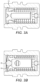
- Fig. 3A uses an elastomeric lip seal 11 to close the valve off to atmosphere.
- Fig. 3B is formed using a ball 12 retained by a disk spring 13.
- Fig. 3C is a simplified variation of Fig. 3A using an elastomeric seal whereby movement of the primary valve ruptures the elastomeric element 14.
- Fig. 3D uses an elastomeric reed seal 15.
- Fig. 3E uses an elastomeric button or flap seal 16.
- the arrangement of this disclosure finds specific application for opening engine nacelle cowls for ground maintenance to ensure that the pressure relief valve operates within the small tolerance ranges required around the set point to avoid damage to the cowl opening system.
- the valve assembly is mounted on or in the hydraulic actuator for opening the cowl.
Landscapes
- Engineering & Computer Science (AREA)
- General Engineering & Computer Science (AREA)
- Mechanical Engineering (AREA)
- Aviation & Aerospace Engineering (AREA)
- Safety Valves (AREA)
- Check Valves (AREA)
Claims (5)
- Hydraulisches Aktuatorsystem zum Öffnen einer Türkonstruktion eines Verkehrsflugzeugs, um für Reparatur oder Wartung Zugang zum Triebwerk zu erhalten, wobei das hydraulische Aktuatorsystem umfasst: einen hydraulischen Türöffnungsaktuator; eine Handpumpe, die an dem hydraulischen Türöffnungsaktuator angebracht ist, um Hydraulikfluid, Öl, zu dem hydraulischen Aktuator zu pumpen; und eine Druckablassventilanordnung, die ein primäres Druckablassventil umfasst, das geöffnet wird, sobald der Pumpdruck von der Pumpe einen Sollwert überschreitet, um die Kraft zu begrenzen, die der hydraulische Aktuator auf die Türkonstruktion ausüben kann, wenn die Tür blockiert ist, wobei die Druckablassventilanordnung umfasst: ein Ventilgehäuse (3), in dem das primäre Druckablassventil, das eine Ventilkugel (1) und eine Ventilfeder (2) aufweist, vorgesehen ist, wobei die Ventilfeder die Ventilkugel in einer ersten, geschlossenen Richtung in einen Ventilsitz (4) vorspannt, um den Durchgang von Fluid aus der Fluidleitung durch das Ventil zu verhindern, und wobei die Federkraft derart gewählt ist, dass eine Fluidkraft über einem vorbestimmten Sollwert, die in einer zweiten Richtung entgegengesetzt der ersten Richtung gegen die Kugel wirkt, veranlasst, dass sich die Kugel gegen die Federkraft aus dem Ventilsitz bewegt, um zu ermöglichen, dass Fluid aus der Fluidleitung durch den Ventilsitz und durch das Ventil fließt; wobei Öl im Inneren des Gehäuses um die Ventilfeder herum bereitgestellt wird; wobei das hydraulische Aktuatorsystem dadurch gekennzeichnet ist, dass die Druckablassventilanordnung ferner umfasst: ein sekundäres Ventil (200), das relativ zu dem primären Ventil im Gehäuse positioniert ist, um das Öl um die Ventilfeder des primären Druckablassventils auf einer Fluidkraft unter dem vorbestimmten Sollwert zu halten, wobei das sekundäre Ventil ein Niederdruckventil ist, das als Ventil mit niedrigerem Druck als das primäre Ventil fungiert und den Kontakt des primären Ventils mit der Atmosphäre sperrt und das Öl in dem primären Ventilgehäuse (3) und um die Ventilfeder (2) hält, sodass die Ventilfeder (2), wenn das primäre Druckablassventil geschlossen und nicht der Atmosphäre ausgesetzt ist, in Öl eingetaucht ist.
- Hydraulisches Aktuatorsystem nach Anspruch 1, wobei das sekundäre Ventil (200) ein Tellerventil ist, das eine Ventilfeder und eine Ventilöffnung umfasst, wobei die Ventilöffnung geschlossen bleibt, um das Fluid um die primäre Ventilfeder bis zum Erreichen des vorbestimmten Sollwerts zu halten, und wobei sich die Ventilöffnung am vorbestimmten Sollwert gegen die Kraft der Feder öffnet, um zu ermöglichen, dass das Fluid durch das Ventilgehäuse abfließt.
- Hydraulisches Aktuatorsystem nach Anspruch 1, wobei das sekundäre Ventil eine Dichtung (11) umfasst, die freigegeben wird, wenn der Sollwert erreicht ist, um zu ermöglichen, dass Fluid durch das Ventilgehäuse abfließt.
- Hydraulisches Aktuatorsystem nach Anspruch 1, wobei das sekundäre Ventil eine Kugel (12) umfasst, die von einer Tellerfeder (13) gehalten wird, wodurch die Tellerfeder freigegeben wird, um die Kugel weg von einer Öffnung zu bewegen, wenn der Sollwert erreicht ist, um zu ermöglichen, dass Fluid durch das Ventilgehäuse abfließt.
- Hydraulisches Aktuatorsystem nach Anspruch 1, wobei das sekundäre Ventil eine Membran (14) umfasst, die zerrissen wird, wenn der Sollwert erreicht ist, um zu ermöglichen, dass Fluid durch das Ventilgehäuse abfließt.
Priority Applications (4)
| Application Number | Priority Date | Filing Date | Title |
|---|---|---|---|
| EP18275271.7A EP3674587B1 (de) | 2018-12-31 | 2018-12-31 | Druckablassventilanordnung |
| CA3057024A CA3057024A1 (en) | 2018-12-31 | 2019-09-26 | Pressure relief valve assembly |
| BR102019020963-1A BR102019020963B1 (pt) | 2018-12-31 | 2019-10-04 | Sistema de atuador hidráulico |
| US16/668,081 US11466788B2 (en) | 2018-12-31 | 2019-10-30 | Pressure relief valve assembly |
Applications Claiming Priority (1)
| Application Number | Priority Date | Filing Date | Title |
|---|---|---|---|
| EP18275271.7A EP3674587B1 (de) | 2018-12-31 | 2018-12-31 | Druckablassventilanordnung |
Publications (2)
| Publication Number | Publication Date |
|---|---|
| EP3674587A1 EP3674587A1 (de) | 2020-07-01 |
| EP3674587B1 true EP3674587B1 (de) | 2023-07-19 |
Family
ID=64901923
Family Applications (1)
| Application Number | Title | Priority Date | Filing Date |
|---|---|---|---|
| EP18275271.7A Active EP3674587B1 (de) | 2018-12-31 | 2018-12-31 | Druckablassventilanordnung |
Country Status (3)
| Country | Link |
|---|---|
| US (1) | US11466788B2 (de) |
| EP (1) | EP3674587B1 (de) |
| CA (1) | CA3057024A1 (de) |
Families Citing this family (2)
| Publication number | Priority date | Publication date | Assignee | Title |
|---|---|---|---|---|
| US11858673B2 (en) * | 2021-09-03 | 2024-01-02 | Altria Client Services Llc | Doser mechanisms |
| US20250377047A1 (en) * | 2024-06-07 | 2025-12-11 | Hamilton Sundstrand Corporation | Aircraft pressure relief valves |
Citations (2)
| Publication number | Priority date | Publication date | Assignee | Title |
|---|---|---|---|---|
| EP1604136B1 (de) * | 2003-03-15 | 2008-02-20 | Neoperl GmbH | Einbauteil zum einsetzen in eine gas- oder flüssigkeitsleitung |
| EP3394487B1 (de) * | 2015-12-21 | 2019-11-20 | Technip France | Differentialventil für flexibles unterwasserrohr |
Family Cites Families (35)
| Publication number | Priority date | Publication date | Assignee | Title |
|---|---|---|---|---|
| US485740A (en) * | 1892-11-08 | Check-valve | ||
| GB191212062A (en) * | 1911-05-23 | 1912-08-08 | Armaturen Und Maschinenfabrik | An Improvement in Air Relief Valves for Diving Apparatus or Equipments. |
| FR472206A (fr) | 1914-05-15 | 1914-11-26 | Isak Eklund | Parapluie à manche télescopique |
| US1889122A (en) * | 1930-11-24 | 1932-11-29 | Westinghouse Air Brake Co | Check valve device |
| US2306012A (en) * | 1941-06-11 | 1942-12-22 | John Eley Jr | Check valve |
| US2500156A (en) * | 1945-06-08 | 1950-03-14 | Frederick H Dechant | Valve and meter apparatus |
| US3426779A (en) * | 1967-02-08 | 1969-02-11 | Kerotest Mfg Corp | Pressure actuated relief valve |
| US3542063A (en) * | 1968-06-06 | 1970-11-24 | Fisher Governor Co | Filler valve |
| US3589397A (en) * | 1970-01-19 | 1971-06-29 | William Wagner | Antirefill valve |
| CH565337A5 (en) * | 1973-02-21 | 1975-08-15 | Straumann Carabbia Sa | Double non-return valve for pressurised lubrication systems - all main valve components are located in constant diameter bore and may be extracted by removal of single plug |
| US4340084A (en) * | 1980-08-28 | 1982-07-20 | Houdaille Industries, Inc. | Check valve |
| US4392507A (en) * | 1981-05-15 | 1983-07-12 | Stant Inc. | Two-stage pressure relief valve |
| FR2597186B1 (fr) * | 1986-04-14 | 1990-01-12 | Europ Propulsion | Soupape ou vanne fonctionnant sans frottement |
| US4953588A (en) * | 1989-08-16 | 1990-09-04 | Mueller Co. | Dual check valve |
| US5168895A (en) * | 1989-09-01 | 1992-12-08 | Richard Voss Grubenausbau Gmbh | Pressure-relief valve with teflon seal |
| DE4021469A1 (de) * | 1990-07-05 | 1992-01-09 | Bosch Gmbh Robert | Rueckschlagventil |
| US5673563A (en) * | 1996-07-08 | 1997-10-07 | Albertson; Luther D. | Pressure relief apparatus and method of use particularly for a refrigeration system |
| US6361458B1 (en) * | 1998-04-20 | 2002-03-26 | Borgwarner Inc. | Hydraulic tensioner with pressure relief valve |
| FR2777966B1 (fr) * | 1998-04-27 | 2000-05-19 | Coflexip | Soupape differentielle pour conduite flexible sous-marine |
| US6206032B1 (en) * | 2000-07-11 | 2001-03-27 | James H. Hill | High pressure check valve fittings |
| US20040079417A1 (en) * | 2001-04-23 | 2004-04-29 | Auad Rogerio Batista | Fluid mixing device and fluid injection valve for use therewith |
| DE10157815A1 (de) * | 2001-11-27 | 2003-06-26 | Knorr Bremse Systeme | Rückschlagventil |
| US6769446B1 (en) * | 2003-08-14 | 2004-08-03 | Wcm Industries, Inc. | Freeze protection device for wall hydrants/faucets |
| US8720648B1 (en) * | 2005-04-27 | 2014-05-13 | Coltec Industrial Products, LLC | Check valve and method and apparatus for extending life of check valves |
| CA2540499A1 (en) * | 2006-03-17 | 2007-09-17 | Gerald Leeb | Dual check valve |
| KR100703762B1 (ko) * | 2006-08-11 | 2007-04-09 | 이상득 | 밸브용 실란트 피팅 |
| US8397749B2 (en) * | 2007-09-07 | 2013-03-19 | Metaldyne Company Llc | Piston cooling jet with tracking ball orifice |
| US8267666B2 (en) * | 2009-08-06 | 2012-09-18 | Campbell Hausfeld/Scott Fetzer Company | Air flow control apparatus |
| DE102014106831A1 (de) | 2014-05-14 | 2015-11-19 | Airbus Operations Gmbh | Passagierflugzeug mit einer Notausstiegstür |
| CN204299361U (zh) | 2014-09-22 | 2015-04-29 | 梁炳饶 | 一种可任意定位的气弹簧闭门器 |
| US9611980B2 (en) * | 2014-10-01 | 2017-04-04 | Curtis Roys | Check valve |
| US9353742B2 (en) * | 2014-10-01 | 2016-05-31 | Curtis Roys | Check valve |
| CN204512560U (zh) * | 2014-12-29 | 2015-07-29 | 张仁本 | 防爆容器及其防爆透气装置 |
| JP6681728B2 (ja) * | 2016-02-03 | 2020-04-15 | キャタピラー エス エー アール エル | 非圧縮性流体注入装置 |
| CN208237154U (zh) * | 2018-02-07 | 2018-12-14 | 佛山市汇莱德电器有限公司 | 一种改进耦合器的进水单向阀 |
-
2018
- 2018-12-31 EP EP18275271.7A patent/EP3674587B1/de active Active
-
2019
- 2019-09-26 CA CA3057024A patent/CA3057024A1/en active Pending
- 2019-10-30 US US16/668,081 patent/US11466788B2/en active Active
Patent Citations (2)
| Publication number | Priority date | Publication date | Assignee | Title |
|---|---|---|---|---|
| EP1604136B1 (de) * | 2003-03-15 | 2008-02-20 | Neoperl GmbH | Einbauteil zum einsetzen in eine gas- oder flüssigkeitsleitung |
| EP3394487B1 (de) * | 2015-12-21 | 2019-11-20 | Technip France | Differentialventil für flexibles unterwasserrohr |
Also Published As
| Publication number | Publication date |
|---|---|
| BR102019020963A2 (pt) | 2020-07-14 |
| US11466788B2 (en) | 2022-10-11 |
| CA3057024A1 (en) | 2020-06-30 |
| US20200208749A1 (en) | 2020-07-02 |
| EP3674587A1 (de) | 2020-07-01 |
Similar Documents
| Publication | Publication Date | Title |
|---|---|---|
| US4508132A (en) | Temperature controlled valve mechanism and method | |
| EP1472446B1 (de) | Aktuator für das ventil eines luftturbinenstarters | |
| US9488291B2 (en) | Method of draining an enclosure using a smart valve | |
| US11466788B2 (en) | Pressure relief valve assembly | |
| EP1963183B1 (de) | Flugzeugwasserablassventil und Verfahren zum Wasserablauf | |
| EP3421847B1 (de) | Sicherheitsbypassventil | |
| US4356833A (en) | Temperature controlled valve mechanism and method | |
| US10458280B2 (en) | Gas turbine engine hydraulically operated nacelle latch | |
| AU2018220011B2 (en) | Spill-resistant vacuum breaker valve | |
| US20100078081A1 (en) | Temperature control valve | |
| JPS63270983A (ja) | 抽出弁 | |
| US20170022906A1 (en) | Method for isolating a combustible fluid tank from a downstream portion of a turbomachine supply system in case of a fire, and such a supply system | |
| US3533390A (en) | Protective device for engine shutdown | |
| US11879394B2 (en) | Shut off valves and components thereof for ecology fuel return systems | |
| EA031610B1 (ru) | Система повышенной надежности для защиты от превышения давления (hipps) для линии подачи текучей среды | |
| US4561468A (en) | Valve for use in jet engine systems and the like | |
| EP0344048A1 (de) | Selbständig öffnendes Ventil und Luftfahrzeug, mit einem derartigen Ventil | |
| US7252068B2 (en) | System and method to reduce fuel system pumping heat input | |
| RU2660745C1 (ru) | Клапан обратный | |
| US2960082A (en) | Engine starting and protective shutdown system | |
| CN114352415A (zh) | 一种适用于预防弹用航空发动机滑油系统气塞的结构 | |
| US11035392B2 (en) | Hydraulic actuator end stroke stop pressure/load control | |
| BR102019020963B1 (pt) | Sistema de atuador hidráulico | |
| CN112814962B (zh) | 小型航空电磁温流阀 | |
| US3752177A (en) | Self venting valve |
Legal Events
| Date | Code | Title | Description |
|---|---|---|---|
| PUAI | Public reference made under article 153(3) epc to a published international application that has entered the european phase |
Free format text: ORIGINAL CODE: 0009012 |
|
| STAA | Information on the status of an ep patent application or granted ep patent |
Free format text: STATUS: THE APPLICATION HAS BEEN PUBLISHED |
|
| AK | Designated contracting states |
Kind code of ref document: A1 Designated state(s): AL AT BE BG CH CY CZ DE DK EE ES FI FR GB GR HR HU IE IS IT LI LT LU LV MC MK MT NL NO PL PT RO RS SE SI SK SM TR |
|
| AX | Request for extension of the european patent |
Extension state: BA ME |
|
| STAA | Information on the status of an ep patent application or granted ep patent |
Free format text: STATUS: REQUEST FOR EXAMINATION WAS MADE |
|
| 17P | Request for examination filed |
Effective date: 20210111 |
|
| RBV | Designated contracting states (corrected) |
Designated state(s): AL AT BE BG CH CY CZ DE DK EE ES FI FR GB GR HR HU IE IS IT LI LT LU LV MC MK MT NL NO PL PT RO RS SE SI SK SM TR |
|
| STAA | Information on the status of an ep patent application or granted ep patent |
Free format text: STATUS: EXAMINATION IS IN PROGRESS |
|
| 17Q | First examination report despatched |
Effective date: 20210217 |
|
| REG | Reference to a national code |
Ref country code: DE Ref legal event code: R079 Free format text: PREVIOUS MAIN CLASS: F16K0017040000 Ipc: B64D0029060000 Ref country code: DE Ref legal event code: R079 Ref document number: 602018053544 Country of ref document: DE Free format text: PREVIOUS MAIN CLASS: F16K0017040000 Ipc: B64D0029060000 |
|
| GRAP | Despatch of communication of intention to grant a patent |
Free format text: ORIGINAL CODE: EPIDOSNIGR1 |
|
| STAA | Information on the status of an ep patent application or granted ep patent |
Free format text: STATUS: GRANT OF PATENT IS INTENDED |
|
| RIC1 | Information provided on ipc code assigned before grant |
Ipc: F16K 15/14 20060101ALI20230117BHEP Ipc: F16K 17/04 20060101ALI20230117BHEP Ipc: B64D 29/06 20060101AFI20230117BHEP |
|
| INTG | Intention to grant announced |
Effective date: 20230203 |
|
| GRAS | Grant fee paid |
Free format text: ORIGINAL CODE: EPIDOSNIGR3 |
|
| GRAA | (expected) grant |
Free format text: ORIGINAL CODE: 0009210 |
|
| STAA | Information on the status of an ep patent application or granted ep patent |
Free format text: STATUS: THE PATENT HAS BEEN GRANTED |
|
| AK | Designated contracting states |
Kind code of ref document: B1 Designated state(s): AL AT BE BG CH CY CZ DE DK EE ES FI FR GB GR HR HU IE IS IT LI LT LU LV MC MK MT NL NO PL PT RO RS SE SI SK SM TR |
|
| REG | Reference to a national code |
Ref country code: GB Ref legal event code: FG4D |
|
| REG | Reference to a national code |
Ref country code: CH Ref legal event code: EP |
|
| REG | Reference to a national code |
Ref country code: DE Ref legal event code: R096 Ref document number: 602018053544 Country of ref document: DE |
|
| REG | Reference to a national code |
Ref country code: IE Ref legal event code: FG4D |
|
| REG | Reference to a national code |
Ref country code: LT Ref legal event code: MG9D |
|
| REG | Reference to a national code |
Ref country code: NL Ref legal event code: MP Effective date: 20230719 |
|
| REG | Reference to a national code |
Ref country code: AT Ref legal event code: MK05 Ref document number: 1589233 Country of ref document: AT Kind code of ref document: T Effective date: 20230719 |
|
| PG25 | Lapsed in a contracting state [announced via postgrant information from national office to epo] |
Ref country code: NL Free format text: LAPSE BECAUSE OF FAILURE TO SUBMIT A TRANSLATION OF THE DESCRIPTION OR TO PAY THE FEE WITHIN THE PRESCRIBED TIME-LIMIT Effective date: 20230719 |
|
| PG25 | Lapsed in a contracting state [announced via postgrant information from national office to epo] |
Ref country code: GR Free format text: LAPSE BECAUSE OF FAILURE TO SUBMIT A TRANSLATION OF THE DESCRIPTION OR TO PAY THE FEE WITHIN THE PRESCRIBED TIME-LIMIT Effective date: 20231020 |
|
| PG25 | Lapsed in a contracting state [announced via postgrant information from national office to epo] |
Ref country code: IS Free format text: LAPSE BECAUSE OF FAILURE TO SUBMIT A TRANSLATION OF THE DESCRIPTION OR TO PAY THE FEE WITHIN THE PRESCRIBED TIME-LIMIT Effective date: 20231119 |
|
| PG25 | Lapsed in a contracting state [announced via postgrant information from national office to epo] |
Ref country code: SE Free format text: LAPSE BECAUSE OF FAILURE TO SUBMIT A TRANSLATION OF THE DESCRIPTION OR TO PAY THE FEE WITHIN THE PRESCRIBED TIME-LIMIT Effective date: 20230719 Ref country code: RS Free format text: LAPSE BECAUSE OF FAILURE TO SUBMIT A TRANSLATION OF THE DESCRIPTION OR TO PAY THE FEE WITHIN THE PRESCRIBED TIME-LIMIT Effective date: 20230719 Ref country code: PT Free format text: LAPSE BECAUSE OF FAILURE TO SUBMIT A TRANSLATION OF THE DESCRIPTION OR TO PAY THE FEE WITHIN THE PRESCRIBED TIME-LIMIT Effective date: 20231120 Ref country code: NO Free format text: LAPSE BECAUSE OF FAILURE TO SUBMIT A TRANSLATION OF THE DESCRIPTION OR TO PAY THE FEE WITHIN THE PRESCRIBED TIME-LIMIT Effective date: 20231019 Ref country code: LV Free format text: LAPSE BECAUSE OF FAILURE TO SUBMIT A TRANSLATION OF THE DESCRIPTION OR TO PAY THE FEE WITHIN THE PRESCRIBED TIME-LIMIT Effective date: 20230719 Ref country code: LT Free format text: LAPSE BECAUSE OF FAILURE TO SUBMIT A TRANSLATION OF THE DESCRIPTION OR TO PAY THE FEE WITHIN THE PRESCRIBED TIME-LIMIT Effective date: 20230719 Ref country code: IS Free format text: LAPSE BECAUSE OF FAILURE TO SUBMIT A TRANSLATION OF THE DESCRIPTION OR TO PAY THE FEE WITHIN THE PRESCRIBED TIME-LIMIT Effective date: 20231119 Ref country code: HR Free format text: LAPSE BECAUSE OF FAILURE TO SUBMIT A TRANSLATION OF THE DESCRIPTION OR TO PAY THE FEE WITHIN THE PRESCRIBED TIME-LIMIT Effective date: 20230719 Ref country code: GR Free format text: LAPSE BECAUSE OF FAILURE TO SUBMIT A TRANSLATION OF THE DESCRIPTION OR TO PAY THE FEE WITHIN THE PRESCRIBED TIME-LIMIT Effective date: 20231020 Ref country code: FI Free format text: LAPSE BECAUSE OF FAILURE TO SUBMIT A TRANSLATION OF THE DESCRIPTION OR TO PAY THE FEE WITHIN THE PRESCRIBED TIME-LIMIT Effective date: 20230719 Ref country code: AT Free format text: LAPSE BECAUSE OF FAILURE TO SUBMIT A TRANSLATION OF THE DESCRIPTION OR TO PAY THE FEE WITHIN THE PRESCRIBED TIME-LIMIT Effective date: 20230719 |
|
| PG25 | Lapsed in a contracting state [announced via postgrant information from national office to epo] |
Ref country code: PL Free format text: LAPSE BECAUSE OF FAILURE TO SUBMIT A TRANSLATION OF THE DESCRIPTION OR TO PAY THE FEE WITHIN THE PRESCRIBED TIME-LIMIT Effective date: 20230719 |
|
| REG | Reference to a national code |
Ref country code: DE Ref legal event code: R097 Ref document number: 602018053544 Country of ref document: DE |
|
| PG25 | Lapsed in a contracting state [announced via postgrant information from national office to epo] |
Ref country code: ES Free format text: LAPSE BECAUSE OF FAILURE TO SUBMIT A TRANSLATION OF THE DESCRIPTION OR TO PAY THE FEE WITHIN THE PRESCRIBED TIME-LIMIT Effective date: 20230719 |
|
| PG25 | Lapsed in a contracting state [announced via postgrant information from national office to epo] |
Ref country code: SM Free format text: LAPSE BECAUSE OF FAILURE TO SUBMIT A TRANSLATION OF THE DESCRIPTION OR TO PAY THE FEE WITHIN THE PRESCRIBED TIME-LIMIT Effective date: 20230719 Ref country code: RO Free format text: LAPSE BECAUSE OF FAILURE TO SUBMIT A TRANSLATION OF THE DESCRIPTION OR TO PAY THE FEE WITHIN THE PRESCRIBED TIME-LIMIT Effective date: 20230719 Ref country code: ES Free format text: LAPSE BECAUSE OF FAILURE TO SUBMIT A TRANSLATION OF THE DESCRIPTION OR TO PAY THE FEE WITHIN THE PRESCRIBED TIME-LIMIT Effective date: 20230719 Ref country code: EE Free format text: LAPSE BECAUSE OF FAILURE TO SUBMIT A TRANSLATION OF THE DESCRIPTION OR TO PAY THE FEE WITHIN THE PRESCRIBED TIME-LIMIT Effective date: 20230719 Ref country code: DK Free format text: LAPSE BECAUSE OF FAILURE TO SUBMIT A TRANSLATION OF THE DESCRIPTION OR TO PAY THE FEE WITHIN THE PRESCRIBED TIME-LIMIT Effective date: 20230719 Ref country code: CZ Free format text: LAPSE BECAUSE OF FAILURE TO SUBMIT A TRANSLATION OF THE DESCRIPTION OR TO PAY THE FEE WITHIN THE PRESCRIBED TIME-LIMIT Effective date: 20230719 Ref country code: SK Free format text: LAPSE BECAUSE OF FAILURE TO SUBMIT A TRANSLATION OF THE DESCRIPTION OR TO PAY THE FEE WITHIN THE PRESCRIBED TIME-LIMIT Effective date: 20230719 |
|
| PLBE | No opposition filed within time limit |
Free format text: ORIGINAL CODE: 0009261 |
|
| STAA | Information on the status of an ep patent application or granted ep patent |
Free format text: STATUS: NO OPPOSITION FILED WITHIN TIME LIMIT |
|
| 26N | No opposition filed |
Effective date: 20240422 |
|
| PG25 | Lapsed in a contracting state [announced via postgrant information from national office to epo] |
Ref country code: SI Free format text: LAPSE BECAUSE OF FAILURE TO SUBMIT A TRANSLATION OF THE DESCRIPTION OR TO PAY THE FEE WITHIN THE PRESCRIBED TIME-LIMIT Effective date: 20230719 |
|
| REG | Reference to a national code |
Ref country code: CH Ref legal event code: PL |
|
| PG25 | Lapsed in a contracting state [announced via postgrant information from national office to epo] |
Ref country code: LU Free format text: LAPSE BECAUSE OF NON-PAYMENT OF DUE FEES Effective date: 20231231 |
|
| PG25 | Lapsed in a contracting state [announced via postgrant information from national office to epo] |
Ref country code: MC Free format text: LAPSE BECAUSE OF FAILURE TO SUBMIT A TRANSLATION OF THE DESCRIPTION OR TO PAY THE FEE WITHIN THE PRESCRIBED TIME-LIMIT Effective date: 20230719 |
|
| REG | Reference to a national code |
Ref country code: BE Ref legal event code: MM Effective date: 20231231 |
|
| PG25 | Lapsed in a contracting state [announced via postgrant information from national office to epo] |
Ref country code: MC Free format text: LAPSE BECAUSE OF FAILURE TO SUBMIT A TRANSLATION OF THE DESCRIPTION OR TO PAY THE FEE WITHIN THE PRESCRIBED TIME-LIMIT Effective date: 20230719 Ref country code: LU Free format text: LAPSE BECAUSE OF NON-PAYMENT OF DUE FEES Effective date: 20231231 |
|
| REG | Reference to a national code |
Ref country code: IE Ref legal event code: MM4A |
|
| PG25 | Lapsed in a contracting state [announced via postgrant information from national office to epo] |
Ref country code: IE Free format text: LAPSE BECAUSE OF NON-PAYMENT OF DUE FEES Effective date: 20231231 |
|
| PG25 | Lapsed in a contracting state [announced via postgrant information from national office to epo] |
Ref country code: BE Free format text: LAPSE BECAUSE OF NON-PAYMENT OF DUE FEES Effective date: 20231231 |
|
| PG25 | Lapsed in a contracting state [announced via postgrant information from national office to epo] |
Ref country code: CH Free format text: LAPSE BECAUSE OF NON-PAYMENT OF DUE FEES Effective date: 20231231 |
|
| PG25 | Lapsed in a contracting state [announced via postgrant information from national office to epo] |
Ref country code: IE Free format text: LAPSE BECAUSE OF NON-PAYMENT OF DUE FEES Effective date: 20231231 Ref country code: CH Free format text: LAPSE BECAUSE OF NON-PAYMENT OF DUE FEES Effective date: 20231231 Ref country code: BE Free format text: LAPSE BECAUSE OF NON-PAYMENT OF DUE FEES Effective date: 20231231 |
|
| PG25 | Lapsed in a contracting state [announced via postgrant information from national office to epo] |
Ref country code: BG Free format text: LAPSE BECAUSE OF FAILURE TO SUBMIT A TRANSLATION OF THE DESCRIPTION OR TO PAY THE FEE WITHIN THE PRESCRIBED TIME-LIMIT Effective date: 20230719 |
|
| PG25 | Lapsed in a contracting state [announced via postgrant information from national office to epo] |
Ref country code: BG Free format text: LAPSE BECAUSE OF FAILURE TO SUBMIT A TRANSLATION OF THE DESCRIPTION OR TO PAY THE FEE WITHIN THE PRESCRIBED TIME-LIMIT Effective date: 20230719 |
|
| PG25 | Lapsed in a contracting state [announced via postgrant information from national office to epo] |
Ref country code: CY Free format text: LAPSE BECAUSE OF FAILURE TO SUBMIT A TRANSLATION OF THE DESCRIPTION OR TO PAY THE FEE WITHIN THE PRESCRIBED TIME-LIMIT; INVALID AB INITIO Effective date: 20181231 |
|
| PG25 | Lapsed in a contracting state [announced via postgrant information from national office to epo] |
Ref country code: HU Free format text: LAPSE BECAUSE OF FAILURE TO SUBMIT A TRANSLATION OF THE DESCRIPTION OR TO PAY THE FEE WITHIN THE PRESCRIBED TIME-LIMIT; INVALID AB INITIO Effective date: 20181231 |
|
| PG25 | Lapsed in a contracting state [announced via postgrant information from national office to epo] |
Ref country code: TR Free format text: LAPSE BECAUSE OF FAILURE TO SUBMIT A TRANSLATION OF THE DESCRIPTION OR TO PAY THE FEE WITHIN THE PRESCRIBED TIME-LIMIT Effective date: 20230719 |
|
| PGFP | Annual fee paid to national office [announced via postgrant information from national office to epo] |
Ref country code: GB Payment date: 20251229 Year of fee payment: 8 |
|
| PGFP | Annual fee paid to national office [announced via postgrant information from national office to epo] |
Ref country code: IT Payment date: 20251210 Year of fee payment: 8 |
|
| PGFP | Annual fee paid to national office [announced via postgrant information from national office to epo] |
Ref country code: FR Payment date: 20251230 Year of fee payment: 8 |
|
| PGFP | Annual fee paid to national office [announced via postgrant information from national office to epo] |
Ref country code: DE Payment date: 20251231 Year of fee payment: 8 |