EP3674611A1 - Système de mise en température des surfaces - Google Patents
Système de mise en température des surfaces Download PDFInfo
- Publication number
- EP3674611A1 EP3674611A1 EP19217877.0A EP19217877A EP3674611A1 EP 3674611 A1 EP3674611 A1 EP 3674611A1 EP 19217877 A EP19217877 A EP 19217877A EP 3674611 A1 EP3674611 A1 EP 3674611A1
- Authority
- EP
- European Patent Office
- Prior art keywords
- temperature control
- heating cable
- surface temperature
- control system
- carrier
- Prior art date
- Legal status (The legal status is an assumption and is not a legal conclusion. Google has not performed a legal analysis and makes no representation as to the accuracy of the status listed.)
- Withdrawn
Links
- 238000005496 tempering Methods 0.000 title 1
- 238000010438 heat treatment Methods 0.000 claims abstract description 92
- 229920003023 plastic Polymers 0.000 claims description 7
- 239000004033 plastic Substances 0.000 claims description 7
- 239000006260 foam Substances 0.000 claims description 6
- 238000009413 insulation Methods 0.000 claims description 6
- 229920000642 polymer Polymers 0.000 claims description 6
- 239000010408 film Substances 0.000 description 25
- 239000010410 layer Substances 0.000 description 18
- 239000004744 fabric Substances 0.000 description 13
- 239000004698 Polyethylene Substances 0.000 description 9
- -1 polyethylene Polymers 0.000 description 9
- 229920000573 polyethylene Polymers 0.000 description 9
- 239000013039 cover film Substances 0.000 description 7
- 238000009434 installation Methods 0.000 description 7
- 239000000463 material Substances 0.000 description 7
- 239000004743 Polypropylene Substances 0.000 description 6
- 229920001155 polypropylene Polymers 0.000 description 6
- 229910052751 metal Inorganic materials 0.000 description 5
- 239000002184 metal Substances 0.000 description 5
- 239000000835 fiber Substances 0.000 description 4
- 229920005830 Polyurethane Foam Polymers 0.000 description 3
- 229910052782 aluminium Inorganic materials 0.000 description 3
- XAGFODPZIPBFFR-UHFFFAOYSA-N aluminium Chemical compound [Al] XAGFODPZIPBFFR-UHFFFAOYSA-N 0.000 description 3
- 238000010276 construction Methods 0.000 description 3
- 239000004800 polyvinyl chloride Substances 0.000 description 3
- 239000011241 protective layer Substances 0.000 description 3
- 239000004753 textile Substances 0.000 description 3
- XLYOFNOQVPJJNP-UHFFFAOYSA-N water Substances O XLYOFNOQVPJJNP-UHFFFAOYSA-N 0.000 description 3
- 239000002131 composite material Substances 0.000 description 2
- 239000004794 expanded polystyrene Substances 0.000 description 2
- 230000002349 favourable effect Effects 0.000 description 2
- 229920001903 high density polyethylene Polymers 0.000 description 2
- 239000004700 high-density polyethylene Substances 0.000 description 2
- 239000002861 polymer material Substances 0.000 description 2
- 239000011496 polyurethane foam Substances 0.000 description 2
- 238000009418 renovation Methods 0.000 description 2
- 239000005871 repellent Substances 0.000 description 2
- 238000010146 3D printing Methods 0.000 description 1
- RYGMFSIKBFXOCR-UHFFFAOYSA-N Copper Chemical compound [Cu] RYGMFSIKBFXOCR-UHFFFAOYSA-N 0.000 description 1
- 239000000853 adhesive Substances 0.000 description 1
- 230000001070 adhesive effect Effects 0.000 description 1
- 239000002390 adhesive tape Substances 0.000 description 1
- 238000005452 bending Methods 0.000 description 1
- 239000000969 carrier Substances 0.000 description 1
- 230000009194 climbing Effects 0.000 description 1
- 239000004020 conductor Substances 0.000 description 1
- 238000001816 cooling Methods 0.000 description 1
- 229910052802 copper Inorganic materials 0.000 description 1
- 239000010949 copper Substances 0.000 description 1
- 230000001419 dependent effect Effects 0.000 description 1
- 229920002457 flexible plastic Polymers 0.000 description 1
- 238000007667 floating Methods 0.000 description 1
- 238000004519 manufacturing process Methods 0.000 description 1
- 229920000915 polyvinyl chloride Polymers 0.000 description 1
- 230000002441 reversible effect Effects 0.000 description 1
- 239000000758 substrate Substances 0.000 description 1
Images
Classifications
-
- F—MECHANICAL ENGINEERING; LIGHTING; HEATING; WEAPONS; BLASTING
- F24—HEATING; RANGES; VENTILATING
- F24D—DOMESTIC- OR SPACE-HEATING SYSTEMS, e.g. CENTRAL HEATING SYSTEMS; DOMESTIC HOT-WATER SUPPLY SYSTEMS; ELEMENTS OR COMPONENTS THEREFOR
- F24D3/00—Hot-water central heating systems
- F24D3/12—Tube and panel arrangements for ceiling, wall, or underfloor heating
- F24D3/14—Tube and panel arrangements for ceiling, wall, or underfloor heating incorporated in a ceiling, wall or floor
- F24D3/141—Tube mountings specially adapted therefor
- F24D3/144—Clips for fastening heating tubes on a reinforcement net or mesh, e.g. mesh for concrete reinforcement
-
- F—MECHANICAL ENGINEERING; LIGHTING; HEATING; WEAPONS; BLASTING
- F24—HEATING; RANGES; VENTILATING
- F24D—DOMESTIC- OR SPACE-HEATING SYSTEMS, e.g. CENTRAL HEATING SYSTEMS; DOMESTIC HOT-WATER SUPPLY SYSTEMS; ELEMENTS OR COMPONENTS THEREFOR
- F24D13/00—Electric heating systems
- F24D13/02—Electric heating systems solely using resistance heating, e.g. underfloor heating
- F24D13/022—Electric heating systems solely using resistance heating, e.g. underfloor heating resistances incorporated in construction elements
- F24D13/024—Electric heating systems solely using resistance heating, e.g. underfloor heating resistances incorporated in construction elements in walls, floors, ceilings
-
- Y—GENERAL TAGGING OF NEW TECHNOLOGICAL DEVELOPMENTS; GENERAL TAGGING OF CROSS-SECTIONAL TECHNOLOGIES SPANNING OVER SEVERAL SECTIONS OF THE IPC; TECHNICAL SUBJECTS COVERED BY FORMER USPC CROSS-REFERENCE ART COLLECTIONS [XRACs] AND DIGESTS
- Y02—TECHNOLOGIES OR APPLICATIONS FOR MITIGATION OR ADAPTATION AGAINST CLIMATE CHANGE
- Y02B—CLIMATE CHANGE MITIGATION TECHNOLOGIES RELATED TO BUILDINGS, e.g. HOUSING, HOUSE APPLIANCES OR RELATED END-USER APPLICATIONS
- Y02B30/00—Energy efficient heating, ventilation or air conditioning [HVAC]
Definitions
- the present invention relates to a surface temperature control system that has at least one flexible heating element, the outside of which is at least partially encased by a first element of a Velcro connection; and a support element, a second element of the Velcro connection being arranged on one side of the support element, so that the flexible heating element (s) can be detachably fixed to the support element while forming the Velcro connection.
- Such surface temperature control systems and flexible heating elements that can be used therein are known from the prior art.
- Surface temperature control systems of this type are used for heating and cooling rooms, pipes which are laid in floors, walls or ceilings and through which a heat transfer medium flows are cast in a screed layer in floors, walls or ceilings.
- the pipelines are usually held on supports by suitable rails or holders.
- it is, for example, from the DE 20 2010 009 133 U1 known to fix the pipes by means of a Velcro connection on the supports.
- a disadvantage of such surface heating systems based on pipelines is seen in the fact that hot water must be generated and stored in the warm season in order to operate the surface heating system.
- the object of the present invention is to provide a surface temperature control system which overcomes at least one of the disadvantages of the prior art.
- the invention should be easy and quick to install in rooms with any floor plan.
- the heating conductor (s) is / are designed as a flexible heating cable with a Velcro jacket.
- the flexible heating cable can be laid anywhere on a support element installed in the room without a specified direction of installation. To correct the installation, the Velcro connection can be released and the flexible heating cable can be installed in the desired changed arrangement. This allows flexible pipe laying that can be adapted to different room geometries. It is not necessary to heat and maintain a heat transfer medium.
- the present invention is to provide a surface temperature control system that has at least one flexible heating element, the outside of which is at least partially encased by a first element of a Velcro connection; and a support element, a second element of the Velcro connection being arranged on one side of the support element, so that the flexible heating element (s) can be detachably fixed to the support element while forming the Velcro connection, the surface temperature system according to the invention being thereby distinguishes that the flexible heating element (s) is / are designed as flexible heating cable (s).
- heating cable means a resistance heating line.
- flexible is used here such that the flexible heating cable used according to the invention enables bending radii which are required for laying a heating element for a surface temperature control system.
- the surface temperature control system it can be preferred if a plurality of heating wires are guided in the heating cable. As a result, the heating of a room can be accelerated by the surface temperature control system according to the invention.
- At least one heating wire is guided in the heating cable, which is guided in one direction in the heating cable in the longitudinal direction of the heating cable, deflected at one end of the heating cable and returned in the opposite direction in the heating cable.
- the heating cable only has to be inserted into and laid in the installation surface. It is not necessary to lead the heating cable out of the installation area. So the heating cable can be laid with even greater variability.
- the first element of the Velcro connection is arranged in a spiral or double spiral shape on the outside of the flexible heating cable. With a low cost of materials, this ensures a high frequency of contact points between the flexible heating cable and the carrier element.
- the carrier element comprises a dimensionally stable, flat carrier, on one side of which a carrier film carrying the second element of the Velcro connection is arranged. This is to ensure a sufficiently strong Velcro connection between a flexible heating cable and the carrier element. It has proven to be particularly favorable if the dimensionally stable, flat support is designed as a polymer foam insulation layer or as a plastic hollow chamber panel. Such a configuration of the dimensionally stable, flat carrier offers a sufficiently strong Velcro connection with inexpensive and easily available carriers.
- Twin-wall sheets made of a plastic material such as preferably polyethylene (PE), polypropylene (PP) and / or polyvinyl chloride (PVC), have sufficient elasticity to be able to lay the flexible heating cable on the plastic twin-wall sheet provided with the carrier film when exposed to external pressure (For example, if the craftsman steps on the corresponding place with one foot or presses or strokes it with his hand) on the twin-wall sheet accordingly.
- PE polyethylene
- PP polypropylene
- PVC polyvinyl chloride
- This increases the contact area between the flexible heating cable and the carrier film, which leads to a stronger Velcro connection.
- such a hollow chamber plate is rigid enough to be able to be laid out on a substrate even at a low height of preferably approximately 2.0 mm to 4.0 mm.
- plastic twin-wall sheets for use in the surface temperature control system according to the invention are in the DE 20 2014 105 1263 U1 describe, which is explicitly referred to herein with respect to the material and structure of a plastic hollow chamber panel as a dimensionally stable, flat carrier.
- polymer foam insulation layers as dimensionally stable, flat supports
- polymer foam insulation layers with a thickness in the range of 1 cm to 20 cm made of materials such as polyurethane foam (PU foam) or expanded polystyrene (EPS) are particularly preferred.
- PU foam polyurethane foam
- EPS expanded polystyrene
- the carrier element is designed as a carrier film in which the second element of the Velcro connection is arranged on at least one side.
- the carrier film itself is the dimensionally stable, flat element, so that a particularly simple surface temperature control system according to the invention with a very low installation height results. This makes it particularly suitable for laying the surface temperature control system according to the invention as underfloor heating for building renovation.
- the carrier element is designed to be foldable and / or rollable. This enables the carrier of the surface temperature control system according to the invention to be easily transported to the place of use.
- the dimensionally stable, flat support or the dimensionally stable, flat element is connected on its side facing away from the second element of the Velcro connection with a cover film, which can preferably be water-repellent. This can effectively prevent leakage water or moisture from getting into the floor of the room.
- the cover film is attached to the dimensionally stable flat carrier, preferably by means of an adhesive or connected in another manner, preferably in a non-detachable manner.
- the cover film is designed as a composite film, the side of which facing the dimensionally stable, flat carrier is designed as a metal layer, preferably as an aluminum layer. With such a structure the insulating properties of the dimensionally stable, flat support can be further increased.
- the cover film comprises a carrier layer, preferably made of paper, and a protective layer, preferably made of polymer material, in particular polyethylene, in addition to the metal layer.
- the carrier film is designed as a composite film, the side of which facing the dimensionally stable, flat carrier is designed as a metal layer, preferably as an aluminum layer. It is particularly preferred that the carrier film comprises, in addition to the metal layer, a carrier layer, preferably made of paper, and a protective layer, preferably made of polymer material, in particular polyethylene.
- the carrier film is preferably provided with the second element of the Velcro connection over the entire surface, preferably the entire surface of the carrier film is provided with the second element of the Velcro connection.
- the flat Velcro connection thus formed enables heating cable to be laid on the entire surface of the carrier film in almost any laying pattern.
- an element of the Velcro connection is formed by hooks, loops and / or fibers which can releasably engage in a knitted fabric, a fleece, a velor fabric or the like of the other element of the Velcro connection.
- the Velcro connection thus ensures a detachable connection between the carrier film and the flexible heating cable, whereby the flexible heating cable is reversibly fixed on the carrier film. It is preferred if the first element of the Velcro connection has the hooks, loops and / or fibers, while the second element of the Velcro connection is formed by the knitted fabric, the fleece, the velor fabric or a plush, terry or other textile fabric.
- the first element of the Velcro connection may be formed by the knitted fabric, the fleece, the velor fabric, the plush, terry cloth or other textile fabric, while the second element of the Velcro connection has the hooks, loops and / or fibers.
- the dimensionally stable flat support or the dimensionally stable, flat element is preferably made so stable that it is suitable for laying the flexible heating cable as part of an underfloor heating system.
- the flexible heating cable comprises a flexible, elastic sheathing between the first element of the Velcro connection of a sheathing of the heating cable.
- the flexible, elastic sheath adapts to the surface of the carrier element due to its elasticity when pressure is exerted on the flexible heating cable from the outside, for example by the installer climbing with the foot on the flexible heating cable or with hand presses or strokes it.
- This increases the contact area between the flexible heating cable and the carrier elements, which leads to a stronger Velcro connection.
- the flexible plastic pipe can be laid as desired on the dimensionally stable flat support provided with the carrier film without a fixed laying direction. Floating the flexible heating cable in a freshly laid screed is largely impossible.
- the surface temperature control system according to the invention and individual parts thereof can also be produced line by line or layer by layer using a line construction or layer construction manufacturing process (e.g. 3D printing).
- a line construction or layer construction manufacturing process e.g. 3D printing
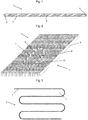
- Fig. 1 shows a section of a flexible heating cable 1 for use in a surface temperature control system 2 according to an embodiment of the present invention.
- the flexible heating cable 1 comprises a sheath 3 made of a polymeric material, in which a heating wire 4, in particular a resistance heating line made of copper, for example, is guided.
- the heating wire 4 is guided in the heating cable 1 in its longitudinal direction, is deflected at one end 5 of the heating cable 1 and is returned in the heating cable 1 in the opposite direction.
- the outside of the flexible heating cable 1 is formed in the form of a spiral by a first element 6 of a Velcro connection.
- the embodiment shown is the casing 3 made of polyethylene (PE).
- the outside of the flexible heating cable 1 forms the first element 6 of the Velcro connection, which is designed as a band, which is arranged in the form of a spiral around the sheathing 3.
- the first element 6 of the Velcro connection comprises hooks, fibers or the like.
- FIG. 2 A section of an embodiment of a surface temperature control system 2 according to the present invention is shown in a perspective view.
- the surface temperature control system 2 according to the invention comprises a flexible heating cable 1 and a carrier element 7, which itself comprises a carrier film 8 and a dimensionally stable, flat carrier 9.
- the flexible heating cable 1 is applied in the surface temperature control system 2 according to the invention to the carrier film 8, which in turn is applied flat to the dimensionally stable flat carrier 9.
- the carrier film 8 On its side facing the flexible heating cable 1, the carrier film 8 comprises a second element 10 of the Velcro connection, which is designed as a knitted fabric, alternatively it can also be designed as a fleece, velor fabric, plush, terry cloth or other textile fabrics.
- the flexible heating cable 1, on the outside of which the first element 6 of the Velcro connection is located, is releasably secured to the carrier element 7 via the second element 10, forming the Velcro connection.
- the dimensionally stable, flat carrier 9 is arranged on the side of the carrier film 8 facing away from the flexible heating cable 1.
- the dimensionally stable, flat carrier 9 is a hollow-chamber plate made of a plastic material, which in the in Fig. 2 embodiment shown is made of polyethylene (PE), in particular high density polyethylene (HDPE).
- PE polyethylene
- HDPE high density polyethylene
- PP polypropylene
- PVC polyvinyl chloride
- PVC-U rigid PVC
- the hollow chamber plate of the Surface temperature control system 2 according to the invention is preferably designed to be foldable and / or rollable.
- the webs of some hollow chambers of the hollow chamber plate on the side of the hollow chamber plate opposite the carrier film 8 may not be present or severed, wherein a severance preferably extends over the entire width of the hollow chamber plate 4.
- a severance preferably extends over the entire width of the hollow chamber plate 4.
- other dimensionally stable, flat supports 9 for example polymer foam insulation layer with a thickness in the range from 1 cm to 20 cm made of materials such as polyurethane foam or expanded polystyrene, can also be used.
- a cover film can be applied, which is preferably made up of a metal layer which is preferably in the form of an aluminum film, a paper carrier and a protective layer which is preferably in the form of a polyethylene film, through which the cover film is water-repellent. This can effectively prevent leakage water or moisture from getting into the floor of the room.
- the dimensionally stable, flat support 9 provided with the carrier film 8 and possibly the cover film is initially laid out over the entire surface of the floor, possibly after being cut to size.
- the flexible heating cable 1 is then placed in a desired laying pattern, for example in a serpentine shape as in FIG Fig. 3 shown, placed on the carrier film 8 and pressed so that a Velcro connection is formed.
- the reversible Velcro connection can be released from the support element 7 by lifting the flexible heating cable 1, after which this can be relocated. Finally, the arrangement is poured with screed.
- the flexible heating cable 1 in the surface temperature control system 2 permits laying flexibility for individual room cross sections, because the flexible heating cable can be laid anywhere on a support element laid in the room. This allows flexible pipe laying that can be adapted to different room geometries. It is not necessary to heat and maintain a heat transfer medium.
Landscapes
- Engineering & Computer Science (AREA)
- Physics & Mathematics (AREA)
- Thermal Sciences (AREA)
- Chemical & Material Sciences (AREA)
- Combustion & Propulsion (AREA)
- Mechanical Engineering (AREA)
- General Engineering & Computer Science (AREA)
- Central Heating Systems (AREA)
Applications Claiming Priority (1)
| Application Number | Priority Date | Filing Date | Title |
|---|---|---|---|
| DE202018107262.5U DE202018107262U1 (de) | 2018-12-19 | 2018-12-19 | Flächentemperierungssystem |
Publications (1)
| Publication Number | Publication Date |
|---|---|
| EP3674611A1 true EP3674611A1 (fr) | 2020-07-01 |
Family
ID=68965812
Family Applications (1)
| Application Number | Title | Priority Date | Filing Date |
|---|---|---|---|
| EP19217877.0A Withdrawn EP3674611A1 (fr) | 2018-12-19 | 2019-12-19 | Système de mise en température des surfaces |
Country Status (2)
| Country | Link |
|---|---|
| EP (1) | EP3674611A1 (fr) |
| DE (1) | DE202018107262U1 (fr) |
Cited By (1)
| Publication number | Priority date | Publication date | Assignee | Title |
|---|---|---|---|---|
| US20230053050A1 (en) * | 2021-08-11 | 2023-02-16 | Infinex Holding Gmbh | Electric surface temperature control system and a laying device for a heating cable of the electric surface temperature control system |
Citations (14)
| Publication number | Priority date | Publication date | Assignee | Title |
|---|---|---|---|---|
| DE2949511A1 (de) | 1979-12-08 | 1981-06-11 | Ferdinand 4600 Dortmund Timmermann | Aufrollbare matte fuer elektrische widerstands-fussbodenheizungen |
| DE29812219U1 (de) | 1998-07-09 | 2000-01-13 | Elektro Bau GmbH, 79112 Freiburg | Wärmeboden mit doppelseitigem Klebeband |
| US20110047907A1 (en) * | 2009-08-28 | 2011-03-03 | DZT Industries, LLC | Method and apparatus for positioning heating elements |
| DE202010009133U1 (de) | 2010-03-25 | 2011-08-18 | Uponor Innovation Ab | Klett-Faserplatte |
| DE102011008442A1 (de) * | 2011-01-12 | 2012-07-12 | Peter bugert | Verlegung und Befestigung von Wärmeübertragungsrohren oder Heizkabeln (z.B.: für Fußbodenheizung) oder Elektrokabel, mit Heiß-/Kaltkleber, im Boden-/,Wand-/und Deckenbereich. |
| EP2530389A2 (fr) * | 2011-05-31 | 2012-12-05 | Hemstedt GmbH | Dispositif de chauffage de surface électrique |
| EP2767765A1 (fr) * | 2013-02-19 | 2014-08-20 | Roth Werke GmbH | Élément de support de tube plat, agrégat de refroidissement et/ou de chauffage et procédé de création d'un agrégat de refroidissement et/ou de chauffage |
| DE202014105163U1 (de) | 2014-10-28 | 2015-08-04 | Rehau Ag + Co | Flächentemperierungssystem |
| DE202015101160U1 (de) * | 2015-03-09 | 2016-03-10 | Rehau Ag + Co | Rohrbund eines Kunststoffrohres sowie mindestens einen von einem derartigen Rohrbund abgewickelten Abschnitt eines Kunststoffrohres umfassendes Flächen-temperierungselement |
| EP2995870A1 (fr) | 2014-09-12 | 2016-03-16 | REHAU AG + Co | Système de régulation de température de surface et méthode de fabrication d'un tel système |
| US9726383B1 (en) * | 2016-06-17 | 2017-08-08 | Progress Profiles S.P.A. | Support for radiant covering and floor heating elements |
| US20180051892A1 (en) * | 2016-04-01 | 2018-02-22 | Progress Profiles S.P.A. | Support for radiant covering and floor heating elements |
| EP3323402A1 (fr) * | 2016-11-16 | 2018-05-23 | RUKU-Sauna Manufaktur GmbH & Co.KG | Dispositif de chauffage de surfaces de parois |
| DE202018106975U1 (de) * | 2017-12-07 | 2018-12-18 | herotec GmbH Flächenheizung | Dämmungsvorrichtung für eine Flächentemperierungsvorrichtung und Flächentemperierungsvorrichtung mit einer Dämmungsvorrichtung |
-
2018
- 2018-12-19 DE DE202018107262.5U patent/DE202018107262U1/de active Active
-
2019
- 2019-12-19 EP EP19217877.0A patent/EP3674611A1/fr not_active Withdrawn
Patent Citations (14)
| Publication number | Priority date | Publication date | Assignee | Title |
|---|---|---|---|---|
| DE2949511A1 (de) | 1979-12-08 | 1981-06-11 | Ferdinand 4600 Dortmund Timmermann | Aufrollbare matte fuer elektrische widerstands-fussbodenheizungen |
| DE29812219U1 (de) | 1998-07-09 | 2000-01-13 | Elektro Bau GmbH, 79112 Freiburg | Wärmeboden mit doppelseitigem Klebeband |
| US20110047907A1 (en) * | 2009-08-28 | 2011-03-03 | DZT Industries, LLC | Method and apparatus for positioning heating elements |
| DE202010009133U1 (de) | 2010-03-25 | 2011-08-18 | Uponor Innovation Ab | Klett-Faserplatte |
| DE102011008442A1 (de) * | 2011-01-12 | 2012-07-12 | Peter bugert | Verlegung und Befestigung von Wärmeübertragungsrohren oder Heizkabeln (z.B.: für Fußbodenheizung) oder Elektrokabel, mit Heiß-/Kaltkleber, im Boden-/,Wand-/und Deckenbereich. |
| EP2530389A2 (fr) * | 2011-05-31 | 2012-12-05 | Hemstedt GmbH | Dispositif de chauffage de surface électrique |
| EP2767765A1 (fr) * | 2013-02-19 | 2014-08-20 | Roth Werke GmbH | Élément de support de tube plat, agrégat de refroidissement et/ou de chauffage et procédé de création d'un agrégat de refroidissement et/ou de chauffage |
| EP2995870A1 (fr) | 2014-09-12 | 2016-03-16 | REHAU AG + Co | Système de régulation de température de surface et méthode de fabrication d'un tel système |
| DE202014105163U1 (de) | 2014-10-28 | 2015-08-04 | Rehau Ag + Co | Flächentemperierungssystem |
| DE202015101160U1 (de) * | 2015-03-09 | 2016-03-10 | Rehau Ag + Co | Rohrbund eines Kunststoffrohres sowie mindestens einen von einem derartigen Rohrbund abgewickelten Abschnitt eines Kunststoffrohres umfassendes Flächen-temperierungselement |
| US20180051892A1 (en) * | 2016-04-01 | 2018-02-22 | Progress Profiles S.P.A. | Support for radiant covering and floor heating elements |
| US9726383B1 (en) * | 2016-06-17 | 2017-08-08 | Progress Profiles S.P.A. | Support for radiant covering and floor heating elements |
| EP3323402A1 (fr) * | 2016-11-16 | 2018-05-23 | RUKU-Sauna Manufaktur GmbH & Co.KG | Dispositif de chauffage de surfaces de parois |
| DE202018106975U1 (de) * | 2017-12-07 | 2018-12-18 | herotec GmbH Flächenheizung | Dämmungsvorrichtung für eine Flächentemperierungsvorrichtung und Flächentemperierungsvorrichtung mit einer Dämmungsvorrichtung |
Cited By (1)
| Publication number | Priority date | Publication date | Assignee | Title |
|---|---|---|---|---|
| US20230053050A1 (en) * | 2021-08-11 | 2023-02-16 | Infinex Holding Gmbh | Electric surface temperature control system and a laying device for a heating cable of the electric surface temperature control system |
Also Published As
| Publication number | Publication date |
|---|---|
| DE202018107262U1 (de) | 2020-03-20 |
Similar Documents
| Publication | Publication Date | Title |
|---|---|---|
| EP3212858B1 (fr) | Système de chauffage au sol | |
| EP1054217B1 (fr) | Procédé de pose d'un chauffage par le sol et plaque de support d' élement de chauffage pour mettre en oeuvre ce procédé | |
| DE202010009133U1 (de) | Klett-Faserplatte | |
| EP2995870B1 (fr) | Système de régulation de température de surface et méthode de fabrication d'un tel système | |
| EP3268671B1 (fr) | Collet tubulaire d'un tuyau en plastique et élément de régulation de température de surfaces comprenant un tronçon, déroulé d'un collet tubulaire de ce type, d'un tuyau en plastique | |
| EP3191756B1 (fr) | Tuyau en matière plastique souple et élément d'équilibrage de température en surface comportant celui-ci | |
| EP3343082B1 (fr) | Système de régulation de température des surfaces | |
| EP3144136B1 (fr) | Feuille de support pour un système de bande velcro d'un système de climatisation de surfaces, ledit système de climatisation de surfaces et procédé destiné a la fabrication d'un système de climatisation de surfaces | |
| EP3674611A1 (fr) | Système de mise en température des surfaces | |
| EP3141821A1 (fr) | Élement d'isolation de sous-sol | |
| EP3144138A1 (fr) | couche velcro de support pour système de montage pour système de régulation de température de surface, système de régulation de température de surface comprenant d'une telle couche et procédé mis en oeuvre dans un tel système | |
| EP4134594B1 (fr) | Système électrique de mise en température de surface | |
| DE3509264C1 (de) | Verfahren zur Installierung von Kunststoffrohren in einer Estrichschicht | |
| DE202019107126U1 (de) | Flächentemperierungselement | |
| EP3674612A1 (fr) | Système de mise en température de surfaces | |
| EP3967936B1 (fr) | Surface de maintien pour un élément de thermorégulation de surface, ainsi que système de thermorégulation de surface comprenant une telle surface | |
| EP3159615A1 (fr) | Haltefläche für ein flächentemperierungselement sowie dieses umfassendes flächentemperierungselement | |
| EP3425287B1 (fr) | Système de mise en température des surfaces | |
| DE102016124572A1 (de) | Flächentemperierungssystem | |
| DE202018101246U1 (de) | Anordnung zur Flächentemperierung in Bereichen mit durchlaufenden Zuleitungen bzw. Anbindeleitungen für Heizkreisverteiler von Flächentemperierungen | |
| DE202017101420U1 (de) | Dämmstreifen für ein Rohr sowie diesen umfassende Rohranordnung | |
| DE102016114024B4 (de) | Thermoelement | |
| DE102018116675A1 (de) | Entkopplungsmatte für Bodenbeläge | |
| DE202021102921U1 (de) | Klimaplatte, Flächenheizung und/oder -kühlung, sowie Wand- oder Fußbodenaufbau | |
| DE202013001168U1 (de) | Verlegeplatte |
Legal Events
| Date | Code | Title | Description |
|---|---|---|---|
| PUAI | Public reference made under article 153(3) epc to a published international application that has entered the european phase |
Free format text: ORIGINAL CODE: 0009012 |
|
| STAA | Information on the status of an ep patent application or granted ep patent |
Free format text: STATUS: THE APPLICATION HAS BEEN PUBLISHED |
|
| AK | Designated contracting states |
Kind code of ref document: A1 Designated state(s): AL AT BE BG CH CY CZ DE DK EE ES FI FR GB GR HR HU IE IS IT LI LT LU LV MC MK MT NL NO PL PT RO RS SE SI SK SM TR |
|
| AX | Request for extension of the european patent |
Extension state: BA ME |
|
| RAP1 | Party data changed (applicant data changed or rights of an application transferred) |
Owner name: REHAU AG + CO |
|
| STAA | Information on the status of an ep patent application or granted ep patent |
Free format text: STATUS: THE APPLICATION IS DEEMED TO BE WITHDRAWN |
|
| 18D | Application deemed to be withdrawn |
Effective date: 20210112 |