EP3674622B1 - Contrôle de fluide pour un circuit de fluide à débit variable d'une unité dans un système hvacr - Google Patents
Contrôle de fluide pour un circuit de fluide à débit variable d'une unité dans un système hvacr Download PDFInfo
- Publication number
- EP3674622B1 EP3674622B1 EP19216639.5A EP19216639A EP3674622B1 EP 3674622 B1 EP3674622 B1 EP 3674622B1 EP 19216639 A EP19216639 A EP 19216639A EP 3674622 B1 EP3674622 B1 EP 3674622B1
- Authority
- EP
- European Patent Office
- Prior art keywords
- flowrate
- bypass line
- flow
- hvacr
- fluid
- Prior art date
- Legal status (The legal status is an assumption and is not a legal conclusion. Google has not performed a legal analysis and makes no representation as to the accuracy of the status listed.)
- Active
Links
Images


Classifications
-
- F—MECHANICAL ENGINEERING; LIGHTING; HEATING; WEAPONS; BLASTING
- F24—HEATING; RANGES; VENTILATING
- F24F—AIR-CONDITIONING; AIR-HUMIDIFICATION; VENTILATION; USE OF AIR CURRENTS FOR SCREENING
- F24F11/00—Control or safety arrangements
- F24F11/62—Control or safety arrangements characterised by the type of control or by internal processing, e.g. using fuzzy logic, adaptive control or estimation of values
- F24F11/63—Electronic processing
- F24F11/64—Electronic processing using pre-stored data
-
- F—MECHANICAL ENGINEERING; LIGHTING; HEATING; WEAPONS; BLASTING
- F28—HEAT EXCHANGE IN GENERAL
- F28F—DETAILS OF HEAT-EXCHANGE AND HEAT-TRANSFER APPARATUS, OF GENERAL APPLICATION
- F28F27/00—Control arrangements or safety devices specially adapted for heat-exchange or heat-transfer apparatus
- F28F27/02—Control arrangements or safety devices specially adapted for heat-exchange or heat-transfer apparatus for controlling the distribution of heat-exchange media between different channels
-
- F—MECHANICAL ENGINEERING; LIGHTING; HEATING; WEAPONS; BLASTING
- F24—HEATING; RANGES; VENTILATING
- F24F—AIR-CONDITIONING; AIR-HUMIDIFICATION; VENTILATION; USE OF AIR CURRENTS FOR SCREENING
- F24F11/00—Control or safety arrangements
- F24F11/89—Arrangement or mounting of control or safety devices
-
- F—MECHANICAL ENGINEERING; LIGHTING; HEATING; WEAPONS; BLASTING
- F25—REFRIGERATION OR COOLING; COMBINED HEATING AND REFRIGERATION SYSTEMS; HEAT PUMP SYSTEMS; MANUFACTURE OR STORAGE OF ICE; LIQUEFACTION SOLIDIFICATION OF GASES
- F25B—REFRIGERATION MACHINES, PLANTS OR SYSTEMS; COMBINED HEATING AND REFRIGERATION SYSTEMS; HEAT PUMP SYSTEMS
- F25B1/00—Compression machines, plants or systems with non-reversible cycle
-
- F—MECHANICAL ENGINEERING; LIGHTING; HEATING; WEAPONS; BLASTING
- F25—REFRIGERATION OR COOLING; COMBINED HEATING AND REFRIGERATION SYSTEMS; HEAT PUMP SYSTEMS; MANUFACTURE OR STORAGE OF ICE; LIQUEFACTION SOLIDIFICATION OF GASES
- F25B—REFRIGERATION MACHINES, PLANTS OR SYSTEMS; COMBINED HEATING AND REFRIGERATION SYSTEMS; HEAT PUMP SYSTEMS
- F25B25/00—Machines, plants or systems, using a combination of modes of operation covered by two or more of the groups F25B1/00 - F25B23/00
- F25B25/005—Machines, plants or systems, using a combination of modes of operation covered by two or more of the groups F25B1/00 - F25B23/00 using primary and secondary systems
-
- F—MECHANICAL ENGINEERING; LIGHTING; HEATING; WEAPONS; BLASTING
- F25—REFRIGERATION OR COOLING; COMBINED HEATING AND REFRIGERATION SYSTEMS; HEAT PUMP SYSTEMS; MANUFACTURE OR STORAGE OF ICE; LIQUEFACTION SOLIDIFICATION OF GASES
- F25B—REFRIGERATION MACHINES, PLANTS OR SYSTEMS; COMBINED HEATING AND REFRIGERATION SYSTEMS; HEAT PUMP SYSTEMS
- F25B41/00—Fluid-circulation arrangements
- F25B41/30—Expansion means; Dispositions thereof
- F25B41/31—Expansion valves
-
- F—MECHANICAL ENGINEERING; LIGHTING; HEATING; WEAPONS; BLASTING
- F25—REFRIGERATION OR COOLING; COMBINED HEATING AND REFRIGERATION SYSTEMS; HEAT PUMP SYSTEMS; MANUFACTURE OR STORAGE OF ICE; LIQUEFACTION SOLIDIFICATION OF GASES
- F25B—REFRIGERATION MACHINES, PLANTS OR SYSTEMS; COMBINED HEATING AND REFRIGERATION SYSTEMS; HEAT PUMP SYSTEMS
- F25B49/00—Arrangement or mounting of control or safety devices
- F25B49/02—Arrangement or mounting of control or safety devices for compression type machines, plants or systems
-
- F—MECHANICAL ENGINEERING; LIGHTING; HEATING; WEAPONS; BLASTING
- F24—HEATING; RANGES; VENTILATING
- F24F—AIR-CONDITIONING; AIR-HUMIDIFICATION; VENTILATION; USE OF AIR CURRENTS FOR SCREENING
- F24F2140/00—Control inputs relating to system states
- F24F2140/50—Load
-
- F—MECHANICAL ENGINEERING; LIGHTING; HEATING; WEAPONS; BLASTING
- F28—HEAT EXCHANGE IN GENERAL
- F28F—DETAILS OF HEAT-EXCHANGE AND HEAT-TRANSFER APPARATUS, OF GENERAL APPLICATION
- F28F2250/00—Arrangements for modifying the flow of the heat exchange media, e.g. flow guiding means; Particular flow patterns
- F28F2250/06—Derivation channels, e.g. bypass
Definitions
- HVAC heating, ventilation, air conditioning, and refrigeration
- a heating, ventilation, air conditioning, and refrigeration (HVACR) system can include a refrigerant circuit having a compressor, a condenser, an expansion valve, and an evaporator fluidly connected.
- a fluid circuit having a temperature controlled fluid can be included in the HVACR system.
- the HVACR system can include a chiller, a boiler, or the like.
- the fluid circuit can include a process fluid (e.g., water, glycol, air, or the like) circulated in a heat exchange relationship with the refrigerant circuit.
- the chiller, boiler, or the like can remove heat from the process fluid via a refrigeration cycle (e.g., a vapor compression cycle).
- the chiller, boiler, or the like can be configured to cool or heat the process fluid to a specific temperature set point(s) based on, for example, a primary function of the process fluid.
- U.S. Publication No. 2006/0010893 is directed to a chiller system including an air handler that can be operated below a minimum capacity by directing at least some fluid used to provide cooling to the air handler through a bypass line in parallel with the air handler.
- U.S. Publication No. 2013/0048114 is directed to a hydronic distribution system including a number of coils and a bypass in parallel with all of the coils that can operate at desired speeds for the pump while providing correct amounts of process fluid flow.
- HVAC heating, ventilation, air conditioning, and refrigeration
- a fluid circuit for an HVACR unit is disclosed.
- the HVACR unit is a chiller.
- the HVACR unit is a boiler.
- the HVACR unit includes a fluid circuit circulating a process fluid.
- HVACR unit in a heating, ventilation, air conditioning, and refrigeration (HVACR) system that includes an HVACR unit through which a process fluid can be pumped to meet a temperature control demand is defined in claim 1.
- HVACCR heating, ventilation, air conditioning, and refrigeration
- a fluid circuit for circulating a process fluid in an HVACR system is defined in claim 10.
- a fluid circuit for circulating a process fluid in a HVACR system is defined in claim 14.
- HVAC heating, ventilation, air conditioning, and refrigeration
- An HVACR unit such as, but not limited to a chiller or a boiler, can generally be used in an HVACR system to remove heat from a process fluid (e.g., water, glycol, air, suitable combinations thereof, or the like) via a refrigeration cycle (e.g., a vapor compression cycle) or to add heat to the process fluid.
- the HVACR unit can be configured to cool or heat the process fluid to a specific temperature set point(s) based on, for example, a primary function of the process fluid.
- the HVACR system can include a single HVACR unit. In some HVACR systems, a plurality of HVACR units can be included. When multiple HVACR units are included in the HVACR system, the HVACR units may have different rated capacities. That is, in an HVACR system with multiple HVACR units, the HVACR units can be sized differently. The particular configuration may be based on, for example, a building size, heating or cooling requirements, or the like.
- An HVACR unit may include a refrigerant circuit (see Figure 2 and its corresponding description below).
- a chiller includes a refrigerant circuit.
- a plurality of chillers can be connected for example in parallel.
- a boiler(s) can heat the process fluid via a heat exchange relationship, e.g., with a gas or other combustible fluid heating the process fluid when combusted.
- the process fluid can have a variable flowrate through the fluid circuit of the HVACR system.
- the process fluid may be circulated at a lower fluid flowrate due to a decreased demand.
- a low cooling load may occur, for example, when the ambient temperature is relatively cooler so that less cooling is required in various conditioned spaces of a building.
- a low heating load may occur, for example, when the ambient temperature is relatively warmer so that less heating is required in various conditioned spaces of a building.
- the fluid flowrate of the process fluid through the HVACR unit may decrease below a minimum acceptable flowrate for the HVACR unit.
- the minimum acceptable flowrate can be based on, for example, requirements established by the manufacturer of the HVACR unit or the like.
- a building operator can establish a minimum acceptable flowrate.
- the building operator may provide a minimum acceptable flowrate that is aimed at, for example, reducing possibility of sediment accumulating in the fluid circuit.
- Embodiments of this disclosure include a valve (e.g., three-way valve) and bypass line installed within the fluid circuit that can be controlled to manage the flowrate of the process fluid and maintain the flowrate above the minimum acceptable flowrate.
- FIG 1 is a perspective view of a chiller 10 of an HVACR system.
- the chiller 10 is an example system in which embodiments and methods described in this Specification can be practiced. It will be appreciated that aspects of the chiller 10 may be modified within the scope of embodiments described in this Specification.
- the chiller 10 includes, among other features, a compressor 12 fluidly connected to a condenser 14, which is fluidly connected to an economizer 16, and an evaporator 18.
- the economizer 16 can be optional.
- the fluidly connected components may form a refrigerant circuit (e.g., refrigerant circuit 50 shown and described in additional detail in accordance with Figure 2 below).
- the chiller 10 is a water-cooled chiller.
- the chiller 10 can alternatively be an air-cooled chiller or the like.
- a fluid used in the refrigerant circuit can be a heat transfer fluid or medium such as a refrigerant or the like which is in a heat exchange relationship with one or more heat transfer fluids or media (e.g., a process fluid) such as, but not limited to, water, glycol, air, suitable combinations thereof, or the like, to cool or chill the process fluid for other use or applications such as, but not limited to, a comfort cooling application, an industrial cooling process application, a commercial cooling process application, or the like.
- a heat transfer fluid or medium such as a refrigerant or the like which is in a heat exchange relationship with one or more heat transfer fluids or media (e.g., a process fluid) such as, but not limited to, water, glycol, air, suitable combinations thereof, or the like, to cool or chill the process fluid for other use or applications such as, but not limited to, a comfort cooling application, an industrial cooling process application, a commercial cooling process application, or the like.
- a process fluid such as, but not limited to
- a control system 20 may control an operation of the chiller 10. It will be appreciated that the chiller 10 and/or the refrigerant circuit for the chiller 10 can include one or more additional features.
- FIG 2 is a schematic diagram of a refrigerant circuit 50.
- the refrigerant circuit 50 is generally representative of a refrigerant circuit that can be used in the chiller 10 in Figure 1 .
- the refrigerant circuit 50 generally includes the compressor 12, the condenser 14, an expansion device 56 (e.g. valve, orifice, expander, or the like), and an evaporator 22.
- the refrigerant circuit 50 is an example and can be modified to include additional components.
- the refrigerant circuit 50 can include other components such as, but not limited to, an economizer heat exchanger (e.g., the economizer 16 in Figure 1 ), one or more flow control devices (e.g., a valve or the like), a receiver tank, a dryer, a suction-liquid heat exchanger, or the like.
- the refrigerant circuit 50 can generally be applied in a variety of systems used to control an environmental condition (e.g., temperature, humidity, air quality, or the like) in a space (generally referred to as a conditioned space).
- an environmental condition e.g., temperature, humidity, air quality, or the like
- the refrigerant circuit 50 can be applied to control the environmental condition to cool an industrial or commercial process load. Examples of such systems include, but are not limited to, HVACR systems or the like.
- the compressor 12, condenser 14, expansion device 56, and evaporator 22 are fluidly connected.
- the refrigerant circuit 50 can operate according to generally known principles.
- the refrigerant circuit 50 can be configured to heat or cool a liquid process fluid (e.g., a heat transfer fluid or medium such as, but not limited to, water, glycol, combinations thereof, or the like), in which case the refrigerant circuit 50 may be generally representative of a liquid chiller system.
- a liquid process fluid e.g., a heat transfer fluid or medium such as, but not limited to, water, glycol, combinations thereof, or the like
- the refrigerant circuit 50 may be generally representative of a liquid chiller system.
- the refrigerant circuit 50 may be implemented in the chiller 10 shown and described above in accordance with Figure 1 above.
- the refrigerant circuit 50 and corresponding chiller e.g., chiller 10) can be connected in parallel to condition the process fluid.
- the compressor 12 compresses a working fluid (e.g., a heat transfer fluid such as a refrigerant or the like) from a relatively lower pressure gas to a relatively higher-pressure gas.
- a working fluid e.g., a heat transfer fluid such as a refrigerant or the like
- the relatively higher-pressure gas is also at a relatively higher temperature, which is discharged from the compressor 12 and flows through the condenser 14.
- the working fluid flows through the condenser 50 and rejects heat to a process fluid (e.g., water, glycol, combinations thereof, or the like), thereby cooling the working fluid.
- a process fluid e.g., water, glycol, combinations thereof, or the like
- the cooled working fluid which is now in a liquid form, flows to the expansion device 56.
- the expansion device 56 reduces the pressure of the working fluid.
- a portion of the working fluid is converted to a gaseous form.
- the working fluid which is now in a mixed liquid and gaseous form flows to the evaporator 22.
- the working fluid flows through the evaporator 22 and absorbs heat from a process fluid (e.g., water, glycol, combinations thereof, or the like), heating the working fluid, and converting it to a gaseous form.
- the gaseous working fluid then returns to the compressor 12.
- a process fluid e.g., water, glycol, combinations thereof, or the like
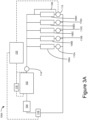
- Figure 3A is a schematic diagram of a fluid circuit 100A, according to an embodiment of the invention.
- the fluid circuit 100A can alternatively be referred to as the process fluid circuit 100A.
- the fluid circuit 100A can alternatively be referred to as the conditioned water circuit 100A, the chilled water circuit 100A, the heated water circuit 100A, or the like.
- the fluid circuit 100A is representative of a process fluid circuit in an HVACR system for controlling a climate in one or more conditioned spaces in a building, for heating or cooling a commercial or industrial process load, suitable combinations thereof, or the like. During operation, there may be minimum flowrates required for the fluid circuit 100A.
- the fluid circuit 100A generally includes an HVACR unit 102; a pump 104; a plurality of terminals 106A - 106N; a bypass line 108; a plurality of valves 110A - 110D; a valve 112; a valve 114; a flowmeter 116; a differential pressure sensor 118; and a controller 120.
- the HVACR unit 102 can be a chiller such as, but not limited to, the chiller 10 in Figure 1 .
- the HVACR unit 102 can be a boiler utilizing a combustible fluid (e.g., natural gas or the like) as a working fluid for heating a process fluid when the working fluid is combusted.
- a combustible fluid e.g., natural gas or the like
- the HVACR unit 102 can include a refrigerant circuit (not shown in Figure 3A ; e.g., the refrigerant circuit 50 discussed in accordance with Figure 2 above). It is to be appreciated that more than one HVACR unit 102 (e.g., see fluid circuit 100B in Figure 3B ) can be present in the fluid circuit 100A.
- the HVACR unit 102 is not intended to be limited to a particular design.
- the HVACR unit 102 can include a refrigerant circuit (not shown) configured to exchange heat with the process fluid (e.g., water, glycol, suitable combinations thereof, or the like).
- the process fluid e.g., water, glycol, suitable combinations thereof, or the like.
- the number of HVACR units 102 in the fluid circuit 100A can be based on, for example, design requirements for a building in which the fluid circuit 100A is implemented.
- the HVACR unit 102 may have minimum flowrate.
- the minimum flowrate can be, for example, a manufacturer's recommended minimum flowrate of the process fluid, a building operator preference, or the like.
- the minimum flowrate can be representative of a flowrate of the process fluid through an evaporator or a condenser of the HVACR unit 102 that ensures effective heat transfer and that a fluid temperature leaving the HVACR unit 102 can be maintained, and can also prevent problems in the heat exchanger (e.g., fouling of the tubes or the like).
- Pump 104 can be used to circulate the process fluid throughout the fluid circuit 100A.
- Pump 104 is representative of a variable flowrate pump. As such, the pump 104 can be operated to provide a variable flowrate to the process fluid circulating throughout the fluid circuit 100A. It is to be appreciated that there can be more than one pump 104 included in the fluid circuit 100A.
- terminals 106A - 106N are shown.
- a terminal as used in this Specification can include any heat transfer device and control valve combination and is not intended to be limited to a particular structure. It will be appreciated that the number of terminals 106A - 106N is illustrative and can vary based on, for example, a building in which the HVACR system is implemented. According to the invention, there is a plurality of terminals.
- the terminals 106A - 106N can include radiant cooling (e.g., panels or tubing which can be embedded into a building structure); chilled beams (e.g., active or passive); fan-powered terminals (e.g., fan-coils, fan-powered variable air volume (VAV) terminals with sensible cooling coils, or the like); air handlers; process cooling load terminals; heat exchange coils in an airstream; dedicated outdoor HVACR units; as well as suitable combinations thereof.
- radiant cooling e.g., panels or tubing which can be embedded into a building structure
- chilled beams e.g., active or passive
- fan-powered terminals e.g., fan-coils, fan-powered variable air volume (VAV) terminals with sensible cooling coils, or the like
- air handlers process cooling load terminals; heat exchange coils in an airstream; dedicated outdoor HVACR units; as well as suitable combinations thereof.
- the terminals 106A - 106D include a valve 110A - 110D. At least one of the terminals 106A - 106N includes a bypass line 108. In the illustrated embodiment, the bypass line 108 is illustrated at the terminal 106N. The bypass line 108 enables a portion of the process fluid to bypass the terminal 106N when the bypass flow is enabled. Accordingly, fluid connections of the bypass line 108 are both upstream of the terminal 106N and downstream of the terminal 106N. For example, an inlet of the bypass line 108 is upstream of the terminal 106N and an outlet of the bypass line 108 is downstream of the terminal 106N.
- a plurality of the terminals 106A - 106N can include bypass line 108. That is, more than one bypass line 108 can be included in the fluid circuit 100A. Any terminal such as the terminal 106N which has the bypass line 108 includes the valve 112 instead of the valve 110A - 110D.
- the particular terminal 106A - 106N that is selected to include the bypass line 108 can be selected so that temperature controlled fluid is provided to a majority of the terminals 106A - 106N even when the bypass line 108 is in a flow enabled state.
- the location of the bypass line 108 can be selected based on, for example, an ease of installing the bypass line 108 or the like.
- the terminals 106A - 106D and the corresponding valves 110A - 110D are selectively actuatable to control a flow of process fluid through the corresponding terminal 106A - 106D.
- the valves 110A - 110D can have two states, a flow enabled state and a flow disabled state.
- the corresponding valves 110A - 110D can be in the flow enabled state so that the temperature controlled process fluid flows through a heat exchange relationship with the corresponding terminals 106A - 106D.
- the corresponding valves 110A - 110D can be in the flow disabled state so that the temperature controlled process fluid does not flow in a heat exchange relationship with the corresponding terminals 106A - 106D.
- the terminals 106A - 106D and the corresponding valves 110A - 110D are separately controllable.
- the valves 110A - 110D can be modulating valves having a flow enabled state, a flow disabled state, and at least one partial flow state.
- the valve 112 is included at the location of the bypass line 108.
- the valve 112 is a three-way valve. In an embodiment, two separate valves may be used in place of the valve 112, though that may increase a complexity of the system.
- the valve 112 includes fluid connections for the bypass line 108 and the primary fluid flow through the terminal 106N. In an embodiment, a default state of the valve 112 is such that flow through the bypass line 108 is disabled. That is, the valve 112 can be set so that it is generally fluidly closed to bypass line 108.
- a portion of the fluid may still flow through the terminal 106N, depending upon a state of the valve 112 with respect to the terminal 106N. That is, the flow through the terminal 106N may be controllable by the valve 112 even when the flow through the bypass line 108 is enabled. In this manner, even when flow of the process fluid through the bypass line 108 is enabled, cooling demands in the conditioned space may still be met via the terminal 106N.
- the valve 112 is selectively modifiable based on an operating condition (e.g., a flowrate of the process fluid, a cooling requirement, combinations thereof, or the like).
- an operating condition e.g., a flowrate of the process fluid, a cooling requirement, combinations thereof, or the like.
- the valve 112 can be selectively enabled or disabled so that process fluid is selectively provided to the terminal 106N according to a cooling requirement.
- the valve 112 can also be selectively enabled or disabled so that the process fluid selectively bypasses the terminal 106N via the bypass line 108.
- the valve 112 enables flow through the bypass line 108, the flow can be enabled through the terminal 106N as well as through the bypass line 108.
- valve 112 and bypass line 108 can be included on one or more of the remaining terminals 106A - 106D.
- the corresponding valve 110A - 110D would be replaced with the valve 112.
- the valves 110A - 110D and the valve 112 are disposed on a downstream side of the terminals 106A - 106N. It is to be appreciated that the valves 110A - 110D and the valve 112 can alternatively be placed on an upstream side of the terminals 106A - 106N, according to an embodiment.
- the bypass line 108 may need to be added to the fluid circuit 100A. That is, the bypass line 108 can be retrofit into an existing fluid circuit to provide the capability of maintaining the flowrate of the process fluid above the minimum flowrate threshold.
- the bypass line 108 and a valve may be present in the fluid circuit 100A when completing the retrofitting of the fluid circuit 100A. However, in such embodiments, the valve may need to be replaced with the valve 112 as described in this Specification.
- the HVACR unit 102 includes valve 114.
- the valve 114 can be selectively controlled to enable or disable fluid flow from the HVACR unit 102. In an embodiment, this control can be based on a cooling load requirement, an operating state of the HVACR unit 102, or the like.
- the fluid circuit 100A can optionally include a sensor 116 for monitoring a flowrate of the fluid in the fluid circuit 100A.
- the sensor 116 is a flowmeter.
- the senor 116 is optional and may not be included in the fluid circuit 100A.
- an alternative way to determine a flowrate of the process fluid can use differential pressure sensor 118.
- the senor 116 and/or the differential pressure sensor 118 can be included to determine the flowrate of the process fluid. Accordingly, when the sensor 116 is present, the differential pressure sensor 118 may not be present in an embodiment. Alternatively, when the differential pressure sensor 118 is present, the sensor 116 may not be present in an embodiment.
- the sensor 116 and/or the differential pressure sensor 118 is electrically connected to the controller 120.
- the valve 112 is also electrically connected to the controller 120.
- the controller 120 can receive values from the sensor 116 and/or the differential pressure sensor 118.
- the controller 120 can selectively control a state (e.g., flow enabled, flow disabled, partial flow, or the like) of the valve 112 based on the values received.
- the differential pressure sensor 118 can be integral to the HVACR unit 102. In an embodiment, the differential pressure sensor 118 may be separate from the HVACR unit 102.
- the controller 120 can determine whether the flowrate as received from the sensor 116 is below a minimum flowrate threshold and take action by enabling the bypass flow through bypass line 108 when the flowrate is below the minimum flowrate threshold.
- the controller 120 can utilize the differential pressure received from the differential pressure sensor 118 to calculate a corresponding flowrate. Then, if the flowrate determined is below the minimum flowrate threshold, the controller 120 can take action by enabling the bypass flow through bypass line 108 when the flowrate is below the minimum flowrate threshold. That is, if the flowrate of the HVACR unit 102 is below the minimum flowrate threshold, then flow through the bypass line 108 can be enabled.
- the controller 120 can be representative of the controller 20 for the chiller unit 10 ( Figure 1 ).
- the controller 120 can be any controller within the HVACR system such as, but not limited to, the chiller controller 20, a controller for a building automation system for the HVACR system, a unit controller corresponding to the terminals 106A - 106N, or the like.
- the controller 120 can be any controller within the HVACR system that is electrically connected to the HVACR unit 102; is electrically connected to the sensor 116 and/or the differential pressure sensor 118; and that is electrically connected to the valve 112.
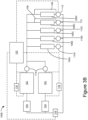
- Figure 3B is a schematic diagram of a fluid circuit 100B, according to a preferred embodiment.
- the fluid circuit 100B can alternatively be referred to as the process fluid circuit 100B.
- the fluid circuit 100B can alternatively be referred to as the conditioned water circuit 100B, the chilled water circuit 100B, the heated water circuit 100B, or the like.
- the fluid circuit 100B is representative of a process fluid circuit in an HVACR system for controlling a climate in one or more conditioned spaces in a building, for heating or cooling a commercial or industrial process load, suitable combinations thereof, or the like. During operation, there may be minimum flowrates required for the fluid circuit 100B.
- the fluid circuit 100B generally differs from the fluid circuit 100A ( Figure 3A ) in that there are a plurality of HVACR units 102 included in the fluid circuit 100B. Further, the terminal 106D includes a second bypass line 108 and valve 112. It is to be noted that a number of bypass lines 108 does not necessarily correspond to a number of HVACR units 102. For example, depending upon the minimum flowrate threshold for a fluid circuit, the number of bypass lines 108 may be selected. Accordingly, in the illustrated embodiment, less than two bypass lines 108 may be sufficient, or more than two bypass lines 108 may be included to meet a minimum flow requirement.
- the fluid circuit 100B generally includes two HVACR units 102; two pumps 104; a plurality of terminals 106A - 106N; bypass lines 108; a plurality of valves 110A - 110D; valves 112; a plurality of valves 114; a flowmeter 116; a plurality of differential pressure sensors 118; and a controller 120.
- Each HVACR unit 102 can include a refrigerant circuit (not shown in Figure 3B ; e.g., the refrigerant circuit 50 discussed in accordance with Figure 2 above). In the illustrated embodiment, two HVACR units 102 are shown. It is to be appreciated that the number of HVACR units 102 is representative and can vary beyond two.
- the HVACR units 102 are not intended to be limited to a particular design.
- the HVACR unit 102 can include a refrigerant circuit (not shown) configured to output the process fluid (e.g., water, glycol, suitable combinations thereof, or the like).
- the process fluid e.g., water, glycol, suitable combinations thereof, or the like.
- the number of HVACR units 102 can be based on, for example, design requirements for a building in which the fluid circuit 100B is implemented.
- the HVACR units 102 can be the same (e.g., same design capacity or the like).
- the HVACR units 102 can be different.
- one of the HVACR units 102 can have a relatively higher rated capacity than the other of the HVACR units 102.
- the HVACR units 102 may have a minimum flowrate.
- the minimum flowrate can be, for example, a manufacturer's recommended minimum flowrate of the process fluid a building operator preference, or the like.
- the minimum flowrate can be representative of a flowrate of the process fluid through an evaporator or a condenser of the HVACR unit 102 that ensures effective heat transfer and that a fluid temperature leaving the HVACR unit 102 can be maintained, and can also prevent problems in the heat exchanger (e.g., fouling of the tubes or the like).
- Pumps 104 can be used to circulate the process fluid throughout the fluid circuit 100B.
- Pumps 104 are representative of variable flowrate pumps. As such, the pumps 104 can be operated to provide a variable flowrate to the process fluid throughout the fluid circuit 100B. In an embodiment, more than two pumps 104 can be included in the fluid circuit 100B.
- terminals 106A - 106N are shown.
- a terminal as used in this Specification can include any heat transfer device and control valve combination and is not intended to be limited to a particular structure. It will be appreciated that the number of terminals 106A - 106N is illustrative and can vary based on, for example, a building in which the HVACR system is implemented.
- the terminals 106A - 106N can include radiant cooling (e.g., panels or tubing which can be embedded into a building structure); chilled beams (e.g., active or passive); fan-powered terminals (e.g., fan-coils, fan-powered variable air volume (VAV) terminals with sensible cooling coils, or the like); air handlers; process cooling load terminals; heat exchange coils in an airstream; dedicated outdoor HVACR units; as well as suitable combinations thereof.
- radiant cooling e.g., panels or tubing which can be embedded into a building structure
- chilled beams e.g., active or passive
- fan-powered terminals e.g., fan-coils, fan-powered variable air volume (VAV) terminals with sensible cooling coils, or the like
- air handlers process cooling load terminals; heat exchange coils in an airstream; dedicated outdoor HVACR units; as well as suitable combinations thereof.
- the terminals 106A - 106C include a valve 110A - 11 0C. At least one of the terminals 106A - 106N includes a bypass line 108. In the illustrated embodiment, the bypass line 108 is illustrated at the terminal 106N. It is to be appreciated that a plurality of the terminals 106A - 106N can include bypass line 108. That is, more than one bypass line 108 can be included in the fluid circuit 100. Any terminal such as the terminal 106N which has the bypass line 108 includes the valve 112 instead of the valve 110A - 110D.
- the bypass line 108 enables at least a portion of the process fluid to bypass the terminal 106N when the bypass flow is enabled. In the embodiment shown in Fig. 3B , terminal 106D has a bypass line 108 and valve 112.
- the terminals 106A - 106C and the corresponding valves 110A - 110C are selectively actuatable to control a flow of process fluid through the corresponding terminal 106A - 106C.
- the valves 110A - 110C can have two states, a flow enabled state and a flow disabled state. In operation, when the terminals 106A - 106C require cooling, the corresponding valves 110A - 110C can be in the flow enabled state so that the temperature controlled process fluid flows through a heat exchange relationship with the corresponding terminals 106A - 106C.
- the corresponding valves 110A - 110C can be in the flow disabled state so that the temperature controlled process fluid does not flow in a heat exchange relationship with the corresponding terminals 106A - 106C. It is to be appreciated that the terminals 106A - 106C and the corresponding valves 110A - 110C are separately controllable. In an embodiment, the valves 110A - 110C can be modulating valves having a flow enabled state, a flow disabled state, and at least one partial flow state.
- the valve 112 is included at the location of the bypass line 108.
- the valve 112 is a three-way valve. In an embodiment, two separate valves may be used in place of the valve 112, though that may increase a complexity of the system.
- the valve 112 includes fluid connections for the bypass line 108 and the primary fluid flow through the terminal 106N and terminal 106D.
- a default state of the valve 112 is such that flow through the bypass line 108 is disabled. That is, the valve 112 can be set so that it is generally fluidly closed to bypass line 108.
- the flow through the terminal 106N (and terminal 106D) and the flow through the bypass line 108 can be independently controlled. That is, flow through the terminal 106N and/or 106D can be modulated to meet a cooling demand regardless of the state of the flow through the bypass line 108. Similarly, flow through the bypass line 108 can be controlled to meet a minimum flowrate threshold regardless of the state of flow through the terminal 106N and/or 106D.
- the valve 112 is selectively modifiable based on an operating condition (e.g., a flowrate of the process fluid, a cooling requirement, combinations thereof, or the like).
- an operating condition e.g., a flowrate of the process fluid, a cooling requirement, combinations thereof, or the like.
- the valve 112 can be selectively enabled or disabled so that process fluid is selectively provided to the terminal 106N (and terminal 106D) according to a cooling requirement.
- the valve 112 can also be selectively enabled or disabled so that the process fluid selectively bypasses the terminal 106N and/or 106D via the bypass line 108.
- the valve 112 enables flow through the bypass line 108
- the flow can be enabled through the terminal 106N and/or 106D as well as through the bypass line 108.
- valve 112 and bypass line 108 can be included on one or more of the remaining terminals 106A - 106C.
- the corresponding valve 110A - 110C would be replaced with the valve 112.
- the valves 110A - 110C and the valve 112 are disposed on a downstream side of the terminals 106A - 106N. It is to be appreciated that the valves 110A - 110C and the valve 112 can alternatively be placed on an upstream side of the terminals 106A - 106N, according to an embodiment.
- the bypass line 108 may need to be added to the fluid circuit 100B. That is, the bypass line 108 can be retrofit into an existing fluid circuit to provide the capability of maintaining the flowrate of the process fluid above the minimum flowrate threshold.
- the bypass line 108 and a valve may be present in the fluid circuit 100B when completing the retrofitting of the fluid circuit 100B. However, in such embodiments, the valve may need to be replaced with the valve 112 as described in this Specification.
- the HVACR units 102 include valves 114.
- the valves 114 can be selectively controlled to enable or disable fluid flow from the corresponding HVACR unit 102. In an embodiment, this control can be based on a cooling load requirement, an operating state of the HVACR units 102, or the like.
- the fluid circuit 100B can include a sensor 116 for monitoring a flowrate of the fluid in the fluid circuit 100B.
- the sensor 116 is a flowmeter.
- the senor 116 is optional and may not be included in the fluid circuit 100B.
- an alternative way to determine a flowrate of the process fluid can use differential pressure sensors 118.
- the senor 116 and/or the differential pressure sensors 118 can be included to determine the flowrate of the process fluid. Accordingly, when the sensor 116 is present, the differential pressure sensors 118 may not be present in an embodiment. Alternatively, when the differential pressure sensors 118 are present, the sensor 116 may not be present in an embodiment.
- the sensor 116 and/or the differential pressure sensors 118 are electrically connected to the controller 120.
- the valve 112 is also electrically connected to the controller 120.
- the controller 120 can receive values from the sensor 116 and/or the differential pressure sensors 118.
- the controller 120 can selectively control a state (e.g., flow enabled, flow disabled, partial flow, or the like) of the valve 112 based on the values received.
- the differential pressure sensor 118 can be integral to the HVACR unit 102. In an embodiment, the differential pressure sensor 118 may be separate from the HVACR unit 102.
- the controller 120 can determine whether the flowrate as received from the sensor 116 is below a minimum flowrate threshold and take action accordingly.
- the controller 120 can utilize the differential pressures received from the differential pressure sensors 118 to calculate a corresponding flowrate. Then, if at least one of the flowrates determined is below a minimum flowrate threshold, the controller 120 can take action accordingly. That is, if the flowrate of either HVACR unit 102 is below the minimum flowrate threshold, then flow through the bypass line 108 can be enabled.
- the controller 120 can be representative of the controller 20 for the HVACR unit 102 ( Figure 1 ).
- the controller 120 can be any controller within the HVACR system such as, but not limited to, the chiller controller 20, a controller for a building automation system for the HVACR system, a unit controller corresponding to the terminals 106A - 106N, or the like.
- the controller 120 can be any controller within the HVACR system that is electrically connected to the chillers 102; is electrically connected to the sensor 116 and/or the differential pressure sensors 118A, 118B; and that is electrically connected to the valve 112.
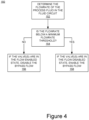
- FIG 4 is a flowchart of a method 150 for controlling a flowrate of a process fluid in a fluid circuit (e.g., the fluid circuit 100A of Figure 3A or the fluid circuit 100B of Figure 3B ) of an HVACR system, according to an embodiment.
- the method 150 can be performed by the controller 120 (e.g., Figure 3 ) to selectively control a state (e.g., flow enabled, flow disabled, or the like) of a valve (e.g., the valve 112 in Figure 3 ) fluidly connected to a bypass line (e.g., bypass line 108 in Figure 3 ) to maintain a flowrate of the process fluid in the fluid circuit (e.g., the fluid circuit 100) that is greater than a minimum flowrate.
- a state e.g., flow enabled, flow disabled, or the like
- a valve e.g., the valve 112 in Figure 3
- bypass line e.g., bypass line 108 in Figure 3
- the controller 120 determines a flowrate of the process fluid in the fluid circuit 100.
- the flowrate can be determined by the controller 120 via a flowrate sensor (e.g., the sensor 116 in Figure 3 ) such as a flowmeter in an embodiment.
- the flowrate can be determined by the controller 120 via a differential pressure sensor (e.g., the differential pressure sensor 118A or 118B).
- the controller 120 compares the flowrate as determined at 152 to a minimum flowrate threshold.
- the minimum flowrate threshold can be, for example, a minimum flowrate that is recommended by a manufacturer of the HVACR unit 102.
- the flowrate may be compared to a minimum flowrate threshold corresponding to each chiller. It will be appreciated that the minimum flowrate threshold for each chiller can be the same, according to an embodiment.
- the controller 120 determines a state of one or more valves 112 to determine whether the valves 112 are in a flow enabled or a flow disabled state at 156. If the valves 112 are in the flow enabled state, the controller 120 switches at least one of the one or more valves 112 to the flow disabled state. After changing the state of the one or more valves 112, the controller 120 continues to determine the flowrate of the process fluid.
- the controller 120 enables a flow of the process fluid through the bypass line at 158.
- the controller 120 may switch all of the one or more valves 112 to the flow enabled state. After changing the state of the one or more valves 112, the controller 120 continues to determine the flowrate of the process fluid.
- the controller 120 can either place all of the valves 112 in the flow enabled state in response to the flowrate falling below the minimum flowrate threshold, or the controller 120 can enable one of the plurality of valves 112 at a time, checking the minimum flowrate after each modulation, to increase the flowrate of the process fluid.
- the method 150 can additionally include a timer.
- the timer may be initiated when the valve 112 changes state and may need to be completed before the valve 112 changes state again. This can, for example, prevent the valve 112 from changing states too quickly.
Landscapes
- Engineering & Computer Science (AREA)
- Mechanical Engineering (AREA)
- General Engineering & Computer Science (AREA)
- Physics & Mathematics (AREA)
- Thermal Sciences (AREA)
- Chemical & Material Sciences (AREA)
- Combustion & Propulsion (AREA)
- Signal Processing (AREA)
- Fuzzy Systems (AREA)
- Mathematical Physics (AREA)
- Air Conditioning Control Device (AREA)
Claims (18)
- Procédé de commande d'une unité HVACR dans un système de chauffage, de ventilation, de climatisation et de réfrigération (HVACR) qui comprend une unité HVACR (102) à travers laquelle un fluide de traitement peut être pompé pour répondre à une demande de commande de température, comprenant :la surveillance, par un dispositif de commande (120), d'un débit du fluide de traitement à travers l'unité HVACR ;caractérisé en ce qu'en réponse à la surveillance :lorsque le débit du fluide de traitement est supérieur à un seuil de débit minimal, fournir le fluide de traitement à une pluralité de terminaux (106A-106N) dans le système HVACR par l'intermédiaire de l'unité HVACR en fonction de la demande de commande de la température, et désactiver un écoulement de dérivation du fluide de traitement à travers une conduite de dérivation (108) configurée pour contourner un terminal sélectionné (106N) de la pluralité de terminaux, en changeant l'état d'une vanne (112) raccordée fluidiquement à la conduite de dérivation et au terminal sélectionné à un état d'écoulement désactivé ;lorsque le débit du fluide de traitement est inférieur au seuil de débit minimal, le dispositif de commande active l'écoulement de dérivation du fluide de traitement à travers la conduite de dérivation en changeant l'état de la vanne raccordée fluidiquement à la conduite de dérivation et au terminal sélectionné à un état d'écoulement activé.
- Procédé selon la revendication 1, la surveillance du débit du fluide de traitement à travers l'unité HVACR comprenant la surveillance d'au moins un capteur parmi un capteur d'écoulement (116) et un capteur de pression différentielle (118).
- Procédé selon l'une quelconque des revendications 1 et 2, le système HVACR comprenant une deuxième unité HVACR à travers laquelle le fluide de traitement peut être pompé pour répondre à la demande de commande de la température, le procédé comprenant en outre la surveillance d'un deuxième débit du fluide de traitement à travers la deuxième unité HVACR.
- Procédé selon la revendication 3, la surveillance du deuxième débit du fluide de traitement comprenant la surveillance d'au moins un capteur parmi un capteur d'écoulement (116) et une pluralité de capteurs de pression différentielle (118), chacun de la pluralité de capteurs de pression différentielle correspondant à la première et à la deuxième unité HVACR.
- Procédé selon l'une quelconque des revendications 3 et 4, le débit et le deuxième débit étant identiques.
- Procédé selon l'une quelconque des revendications 3 à 5, l'activation, par le dispositif de commande, de l'écoulement de dérivation du fluide de traitement à travers la conduite de dérivation (108) en changeant l'état de la vanne (112), raccordée fluidiquement à la conduite de dérivation et au terminal sélectionné, à un état d'écoulement activé, se produisant en réponse au débit étant inférieur au seuil de débit minimal ou en réponse au deuxième débit étant inférieur au seuil de débit minimal.
- Procédé selon la revendication 6, le seuil de débit minimal comprenant un premier seuil de débit minimal pour l'unité HVACR et un deuxième seuil de débit minimal pour la deuxième unité HVACR qui est différent du premier seuil de débit minimal, par l'activation, par le dispositif de commande, de l'écoulement de dérivation du fluide de traitement à travers la conduite de dérivation (108) en changeant l'état de la vanne (112), raccordée fluidiquement à la conduite de dérivation et au terminal sélectionné, à un état d'écoulement activé, se produisant en réponse au débit étant inférieur au premier seuil de débit minimal ou au deuxième seuil de débit minimal, ou par l'activation, par le dispositif de commande, de l'écoulement de dérivation du fluide de traitement à travers la conduite de dérivation en changeant l'état de la vanne raccordée fluidiquement à la conduite de dérivation et au terminal sélectionné pour un état d'écoulement activé en réponse au deuxième débit étant inférieur au premier seuil de débit minimal ou au deuxième seuil de débit minimal.
- Procédé selon l'une quelconque des revendications 1 à 7, le changement d'état de la vanne (112) raccordée fluidiquement à la conduite de dérivation (108) et au terminal sélectionné à un état d'écoulement activé comprenant le changement d'état d'une pluralité de vannes raccordées fluidiquement à la pluralité de terminaux et à une pluralité de conduites de dérivation.
- Procédé selon l'une quelconque des revendications 1 à 8, la vanne (112) étant une vanne à trois voies.
- Circuit de fluide pour faire circuler un fluide de traitement dans un système de chauffage, de ventilation, de climatisation et de réfrigération (HVACR), comprenant :une unité HVACR (102) ;une pompe à débit variable (104) ;une pluralité de terminaux (106A-106N) ;caractérisé en ce qu'un terminal sélectionné (106N) de la pluralité de terminaux comprend une conduite de dérivation (108) configurée de manière à ce qu'une partie d'un fluide dans le circuit de fluide s'écoulant à travers la conduite de dérivation contourne le terminal sélectionné ;le terminal sélectionné comprenant la conduite de dérivation ayant une vanne (112) raccordée fluidiquement au terminal sélectionné et raccordée fluidiquement à la conduite de dérivation, un état de commande d'écoulement du fluide à travers la conduite de dérivation étant sélectivement commandé pour maintenir un débit minimal du fluide de traitement à travers l'unité HVACR ; etun dispositif de commande (120) configuré pour surveiller un débit du fluide de traitement dans le circuit de fluide et pour commander l'état de commande d'écoulement de la conduite de dérivation.
- Circuit de fluide selon la revendication 10, une pluralité de terminaux comprenant chacun une conduite de dérivation respective (108), chaque conduite de dérivation ayant une vanne respective (112) raccordée fluidiquement au terminal respectif.
- Circuit de fluide selon l'une quelconque des revendications 10 et 11, la ou chaque vanne (112) étant une vanne à trois voies comprenant une entrée en aval du terminal respectif, une entrée de la conduite de dérivation (108), et une sortie, et un écoulement à travers le terminal respectif étant commandable séparément d'un écoulement à travers la conduite de dérivation.
- Circuit de fluide selon l'une quelconque des revendications 10 à 12, un écoulement à travers la ou chaque conduite de dérivation (108) étant indépendamment actionnable par rapport à un écoulement à travers le terminal respectif.
- Circuit de fluide pour faire circuler un fluide de traitement dans un système de chauffage, de ventilation, de climatisation et de réfrigération (HVACR), comprenant :une pluralité d'unités HVACR (102), comprenant :une première unité HVACR ayant un premier seuil de débit minimal ; etune deuxième unité HVACR ayant un deuxième seuil de débit minimal ;une première pompe à débit variable (104) associée à la première unité HVACR ;une deuxième pompe à débit variable (104) associée à la deuxième unité HVACR ;une pluralité de terminaux (106A-106N) pour fournir une commande de la température à un espace climatisé dans le système HVACR,caractérisé en ce qu'un terminal sélectionné de la pluralité de terminaux comprend une conduite de dérivation (108) configurée de manière à ce qu'une partie du fluide de traitement dans le circuit de fluide s'écoulant à travers la conduite de dérivation contourne le terminal sélectionné ;le terminal sélectionné comprenant la conduite de dérivation ayant une vanne (112) raccordée fluidiquement au terminal sélectionné de la pluralité de terminaux et raccordée fluidiquement à la conduite de dérivation, un état de commande d'écoulement du fluide à travers la conduite de dérivation étant sélectivement commandé pour maintenir un débit minimal du fluide de traitement à travers la première unité HVACR et la deuxième unité HVACR ; etun dispositif de commande (120) configuré pour surveiller un débit du fluide de traitement dans le circuit de fluide et pour commander l'état de commande d'écoulement de la conduite de dérivation.
- Circuit de fluide selon la revendication 14, un deuxième de la pluralité de terminaux comprenant une deuxième conduite de dérivation (108).
- Circuit de fluide selon l'une quelconque des revendications 14 ou 15, la vanne (112) étant mise par défaut dans un état dans lequel l'écoulement à travers la conduite de dérivation est désactivé.
- Circuit de fluide selon l'une quelconque des revendications 14 à 16, le dispositif de commande (120) étant configuré pour activer sélectivement l'écoulement à travers la conduite de dérivation (108) en changeant la vanne (112) à un état d'écoulement activé dans lequel l'écoulement à travers la conduite de dérivation est activé en réponse au débit tel que surveillé étant inférieur à un seuil de débit minimal.
- Circuit de fluide selon la revendication 17, le seuil de débit minimal étant relativement inférieur au premier seuil de débit minimal et au deuxième seuil de débit minimal.
Applications Claiming Priority (1)
| Application Number | Priority Date | Filing Date | Title |
|---|---|---|---|
| US16/233,949 US20200208927A1 (en) | 2018-12-27 | 2018-12-27 | Fluid control for a variable flow fluid circuit in an hvacr system |
Publications (2)
| Publication Number | Publication Date |
|---|---|
| EP3674622A1 EP3674622A1 (fr) | 2020-07-01 |
| EP3674622B1 true EP3674622B1 (fr) | 2023-05-17 |
Family
ID=68917674
Family Applications (1)
| Application Number | Title | Priority Date | Filing Date |
|---|---|---|---|
| EP19216639.5A Active EP3674622B1 (fr) | 2018-12-27 | 2019-12-16 | Contrôle de fluide pour un circuit de fluide à débit variable d'une unité dans un système hvacr |
Country Status (3)
| Country | Link |
|---|---|
| US (2) | US20200208927A1 (fr) |
| EP (1) | EP3674622B1 (fr) |
| CN (1) | CN111380169B (fr) |
Families Citing this family (2)
| Publication number | Priority date | Publication date | Assignee | Title |
|---|---|---|---|---|
| CA3083899A1 (fr) * | 2020-06-18 | 2021-12-18 | John Faiczak | Methode, appareil et systeme pour equilibrer la pression de fluide de systemes de distribution de fluide |
| CN115047922B (zh) * | 2022-06-01 | 2025-07-15 | 中国科学院微小卫星创新研究院 | 强电环境下大电流设备流体回路控温系统及其控温方法 |
Family Cites Families (31)
| Publication number | Priority date | Publication date | Assignee | Title |
|---|---|---|---|---|
| US5743102A (en) | 1996-04-15 | 1998-04-28 | Hussmann Corporation | Strategic modular secondary refrigeration |
| US6102113A (en) * | 1997-09-16 | 2000-08-15 | B/E Aerospace | Temperature control of individual tools in a cluster tool system |
| US5946926A (en) * | 1998-04-07 | 1999-09-07 | Hartman; Thomas B. | Variable flow chilled fluid cooling system |
| US6651451B2 (en) * | 2002-04-23 | 2003-11-25 | Vai Holdings, Llc | Variable capacity refrigeration system with a single-frequency compressor |
| KR100437805B1 (ko) * | 2002-06-12 | 2004-06-30 | 엘지전자 주식회사 | 냉난방 동시형 멀티공기조화기 및 그 제어방법 |
| US6666042B1 (en) | 2002-07-01 | 2003-12-23 | American Standard International Inc. | Sequencing of variable primary flow chiller system |
| US6792765B2 (en) | 2002-08-23 | 2004-09-21 | Frank L. Domnick | Chilling system and method |
| US7028768B2 (en) | 2003-08-20 | 2006-04-18 | Itt Manufacturing Enterprises, Inc. | Fluid heat exchange control system |
| US20060010893A1 (en) * | 2004-07-13 | 2006-01-19 | Daniel Dominguez | Chiller system with low capacity controller and method of operating same |
| JP4975168B2 (ja) | 2009-02-13 | 2012-07-11 | 東芝キヤリア株式会社 | 二次ポンプ方式熱源システム及び二次ポンプ方式熱源制御方法 |
| WO2010113296A1 (fr) | 2009-04-01 | 2010-10-07 | 三菱電機株式会社 | Dispositif de climatisation |
| US8275483B2 (en) | 2009-07-23 | 2012-09-25 | Siemens Industry, Inc. | Demand flow pumping |
| IT1400806B1 (it) | 2010-07-05 | 2013-07-02 | Emerson Network Power Srl | Dispositivo economizzatore di consumi per macchine refrigeratrici di tipo chiller |
| JP5602243B2 (ja) | 2010-11-19 | 2014-10-08 | 三菱電機株式会社 | 空気調和機 |
| WO2012077166A1 (fr) | 2010-12-09 | 2012-06-14 | 三菱電機株式会社 | Climatiseur |
| GB201104867D0 (en) | 2011-03-23 | 2011-05-04 | Isentropic Ltd | Improved thermal storage system |
| DE102012205200B4 (de) | 2011-04-04 | 2020-06-18 | Denso Corporation | Kältemittelkreislaufvorrichtung |
| US20130048114A1 (en) * | 2011-08-26 | 2013-02-28 | Optimum Energy, Llc | Controlled hydronic distribution system |
| ES2632004T3 (es) * | 2011-10-25 | 2017-09-07 | Lg Electronics Inc. | Aire acondicionado y procedimiento de operación del mismo |
| JP5920178B2 (ja) | 2011-12-05 | 2016-05-18 | 株式会社デンソー | ヒートポンプサイクル |
| CN102705956B (zh) * | 2012-06-01 | 2014-07-30 | 武汉裕生智能节能设备有限公司 | 一种一次泵变流量系统的优化控制装置及方法 |
| US9534795B2 (en) | 2012-10-05 | 2017-01-03 | Schneider Electric Buildings, Llc | Advanced valve actuator with remote location flow reset |
| US9759457B1 (en) | 2012-10-16 | 2017-09-12 | Amazon Technologies, Inc. | Controls solution for primary-secondary chiller plant |
| DE102013111053A1 (de) | 2013-01-18 | 2014-07-24 | Rittal Gmbh & Co. Kg | Verfahren zum Klimatisieren einer IT-Umgebung bzw. einer Umgebung, die Wärmeerzeuger enthält |
| JP2015186989A (ja) | 2014-03-12 | 2015-10-29 | カルソニックカンセイ株式会社 | 車載温調装置、車両用空調装置及びバッテリ温調装置 |
| WO2015171196A1 (fr) | 2014-05-05 | 2015-11-12 | Carrier Corporation | Système de mesure de débit virtuel |
| JP6375893B2 (ja) | 2014-11-19 | 2018-08-22 | 株式会社デンソー | 熱管理装置 |
| WO2016128016A1 (fr) | 2015-02-09 | 2016-08-18 | Carrier Corporation | Système de réfrigération et de chauffage |
| US10655504B2 (en) | 2016-05-27 | 2020-05-19 | Denso International America, Inc. | Heat pump for warming engine coolant |
| DE102016214797A1 (de) | 2016-08-09 | 2018-02-15 | Bayerische Motoren Werke Aktiengesellschaft | Berücksichtigung des Öl-Einflusses in einem Klima-Kälte-Kreislauf |
| US10551078B2 (en) | 2017-06-12 | 2020-02-04 | Kenneth L. Eiermann | Methods and apparatus for latent heat extraction |
-
2018
- 2018-12-27 US US16/233,949 patent/US20200208927A1/en not_active Abandoned
-
2019
- 2019-12-16 EP EP19216639.5A patent/EP3674622B1/fr active Active
- 2019-12-26 CN CN201911368497.1A patent/CN111380169B/zh active Active
-
2023
- 2023-06-20 US US18/338,063 patent/US12135175B2/en active Active
Also Published As
| Publication number | Publication date |
|---|---|
| US12135175B2 (en) | 2024-11-05 |
| US20230332850A1 (en) | 2023-10-19 |
| EP3674622A1 (fr) | 2020-07-01 |
| CN111380169B (zh) | 2023-04-14 |
| CN111380169A (zh) | 2020-07-07 |
| US20200208927A1 (en) | 2020-07-02 |
Similar Documents
| Publication | Publication Date | Title |
|---|---|---|
| US11774154B2 (en) | Systems and methods for controlling a refrigeration system | |
| US12173940B2 (en) | Air conditioning system with capacity control and controlled hot water generation | |
| US12578124B2 (en) | Integrated demand water heating using a capacity modulated heat pump with desuperheater | |
| US10215427B2 (en) | Air conditioning system and method for controlling air conditioning system | |
| EP3587933B1 (fr) | Commande de transfert de réfrigérant dans un climatiseur multimode avec générateur d'eau chaude | |
| WO2016201172A1 (fr) | Système de refroidissement à détente directe et refroidissement à économie de réfrigérant pompé | |
| US12135175B2 (en) | Fluid control for a variable flow fluid circuit in an HVACR system | |
| US10760828B2 (en) | Chiller plant with ice storage | |
| US10539343B2 (en) | Heat source side unit and air-conditioning apparatus | |
| EP4118384B1 (fr) | Unité de refroidissement libre pour système de gestion de température | |
| JP7306582B2 (ja) | 冷凍サイクル装置 | |
| GB2578533A (en) | Refrigeration cycle device | |
| KR20100024157A (ko) | 히트펌프 시스템 및 그 제어방법 | |
| WO2008114952A1 (fr) | Système de conditionnement d'air à plusieurs unités et procédé de régulation correspondant | |
| US20250216127A1 (en) | Cooling-heating units with prioritized loading, system thereof, and method thereof | |
| JP2007051795A (ja) | 空気調和装置 |
Legal Events
| Date | Code | Title | Description |
|---|---|---|---|
| PUAI | Public reference made under article 153(3) epc to a published international application that has entered the european phase |
Free format text: ORIGINAL CODE: 0009012 |
|
| STAA | Information on the status of an ep patent application or granted ep patent |
Free format text: STATUS: THE APPLICATION HAS BEEN PUBLISHED |
|
| AK | Designated contracting states |
Kind code of ref document: A1 Designated state(s): AL AT BE BG CH CY CZ DE DK EE ES FI FR GB GR HR HU IE IS IT LI LT LU LV MC MK MT NL NO PL PT RO RS SE SI SK SM TR |
|
| AX | Request for extension of the european patent |
Extension state: BA ME |
|
| STAA | Information on the status of an ep patent application or granted ep patent |
Free format text: STATUS: REQUEST FOR EXAMINATION WAS MADE |
|
| 17P | Request for examination filed |
Effective date: 20201221 |
|
| RBV | Designated contracting states (corrected) |
Designated state(s): AL AT BE BG CH CY CZ DE DK EE ES FI FR GB GR HR HU IE IS IT LI LT LU LV MC MK MT NL NO PL PT RO RS SE SI SK SM TR |
|
| RIC1 | Information provided on ipc code assigned before grant |
Ipc: F25B 49/02 20060101ALI20220311BHEP Ipc: F25B 25/00 20060101ALI20220311BHEP Ipc: F24F 11/89 20180101AFI20220311BHEP |
|
| GRAP | Despatch of communication of intention to grant a patent |
Free format text: ORIGINAL CODE: EPIDOSNIGR1 |
|
| STAA | Information on the status of an ep patent application or granted ep patent |
Free format text: STATUS: GRANT OF PATENT IS INTENDED |
|
| INTG | Intention to grant announced |
Effective date: 20220506 |
|
| GRAJ | Information related to disapproval of communication of intention to grant by the applicant or resumption of examination proceedings by the epo deleted |
Free format text: ORIGINAL CODE: EPIDOSDIGR1 |
|
| STAA | Information on the status of an ep patent application or granted ep patent |
Free format text: STATUS: REQUEST FOR EXAMINATION WAS MADE |
|
| INTC | Intention to grant announced (deleted) | ||
| GRAP | Despatch of communication of intention to grant a patent |
Free format text: ORIGINAL CODE: EPIDOSNIGR1 |
|
| STAA | Information on the status of an ep patent application or granted ep patent |
Free format text: STATUS: GRANT OF PATENT IS INTENDED |
|
| INTG | Intention to grant announced |
Effective date: 20221124 |
|
| GRAS | Grant fee paid |
Free format text: ORIGINAL CODE: EPIDOSNIGR3 |
|
| GRAA | (expected) grant |
Free format text: ORIGINAL CODE: 0009210 |
|
| STAA | Information on the status of an ep patent application or granted ep patent |
Free format text: STATUS: THE PATENT HAS BEEN GRANTED |
|
| AK | Designated contracting states |
Kind code of ref document: B1 Designated state(s): AL AT BE BG CH CY CZ DE DK EE ES FI FR GB GR HR HU IE IS IT LI LT LU LV MC MK MT NL NO PL PT RO RS SE SI SK SM TR |
|
| REG | Reference to a national code |
Ref country code: GB Ref legal event code: FG4D |
|
| REG | Reference to a national code |
Ref country code: DE Ref legal event code: R096 Ref document number: 602019029047 Country of ref document: DE |
|
| REG | Reference to a national code |
Ref country code: CH Ref legal event code: EP |
|
| REG | Reference to a national code |
Ref country code: IE Ref legal event code: FG4D |
|
| P01 | Opt-out of the competence of the unified patent court (upc) registered |
Effective date: 20230505 |
|
| REG | Reference to a national code |
Ref country code: AT Ref legal event code: REF Ref document number: 1568524 Country of ref document: AT Kind code of ref document: T Effective date: 20230615 |
|
| REG | Reference to a national code |
Ref country code: LT Ref legal event code: MG9D |
|
| REG | Reference to a national code |
Ref country code: NL Ref legal event code: MP Effective date: 20230517 |
|
| REG | Reference to a national code |
Ref country code: AT Ref legal event code: MK05 Ref document number: 1568524 Country of ref document: AT Kind code of ref document: T Effective date: 20230517 |
|
| PG25 | Lapsed in a contracting state [announced via postgrant information from national office to epo] |
Ref country code: SE Free format text: LAPSE BECAUSE OF FAILURE TO SUBMIT A TRANSLATION OF THE DESCRIPTION OR TO PAY THE FEE WITHIN THE PRESCRIBED TIME-LIMIT Effective date: 20230517 Ref country code: PT Free format text: LAPSE BECAUSE OF FAILURE TO SUBMIT A TRANSLATION OF THE DESCRIPTION OR TO PAY THE FEE WITHIN THE PRESCRIBED TIME-LIMIT Effective date: 20230918 Ref country code: NO Free format text: LAPSE BECAUSE OF FAILURE TO SUBMIT A TRANSLATION OF THE DESCRIPTION OR TO PAY THE FEE WITHIN THE PRESCRIBED TIME-LIMIT Effective date: 20230817 Ref country code: NL Free format text: LAPSE BECAUSE OF FAILURE TO SUBMIT A TRANSLATION OF THE DESCRIPTION OR TO PAY THE FEE WITHIN THE PRESCRIBED TIME-LIMIT Effective date: 20230517 Ref country code: ES Free format text: LAPSE BECAUSE OF FAILURE TO SUBMIT A TRANSLATION OF THE DESCRIPTION OR TO PAY THE FEE WITHIN THE PRESCRIBED TIME-LIMIT Effective date: 20230517 Ref country code: AT Free format text: LAPSE BECAUSE OF FAILURE TO SUBMIT A TRANSLATION OF THE DESCRIPTION OR TO PAY THE FEE WITHIN THE PRESCRIBED TIME-LIMIT Effective date: 20230517 |
|
| PG25 | Lapsed in a contracting state [announced via postgrant information from national office to epo] |
Ref country code: RS Free format text: LAPSE BECAUSE OF FAILURE TO SUBMIT A TRANSLATION OF THE DESCRIPTION OR TO PAY THE FEE WITHIN THE PRESCRIBED TIME-LIMIT Effective date: 20230517 Ref country code: PL Free format text: LAPSE BECAUSE OF FAILURE TO SUBMIT A TRANSLATION OF THE DESCRIPTION OR TO PAY THE FEE WITHIN THE PRESCRIBED TIME-LIMIT Effective date: 20230517 Ref country code: LV Free format text: LAPSE BECAUSE OF FAILURE TO SUBMIT A TRANSLATION OF THE DESCRIPTION OR TO PAY THE FEE WITHIN THE PRESCRIBED TIME-LIMIT Effective date: 20230517 Ref country code: LT Free format text: LAPSE BECAUSE OF FAILURE TO SUBMIT A TRANSLATION OF THE DESCRIPTION OR TO PAY THE FEE WITHIN THE PRESCRIBED TIME-LIMIT Effective date: 20230517 Ref country code: IS Free format text: LAPSE BECAUSE OF FAILURE TO SUBMIT A TRANSLATION OF THE DESCRIPTION OR TO PAY THE FEE WITHIN THE PRESCRIBED TIME-LIMIT Effective date: 20230917 Ref country code: HR Free format text: LAPSE BECAUSE OF FAILURE TO SUBMIT A TRANSLATION OF THE DESCRIPTION OR TO PAY THE FEE WITHIN THE PRESCRIBED TIME-LIMIT Effective date: 20230517 Ref country code: GR Free format text: LAPSE BECAUSE OF FAILURE TO SUBMIT A TRANSLATION OF THE DESCRIPTION OR TO PAY THE FEE WITHIN THE PRESCRIBED TIME-LIMIT Effective date: 20230818 |
|
| PG25 | Lapsed in a contracting state [announced via postgrant information from national office to epo] |
Ref country code: FI Free format text: LAPSE BECAUSE OF FAILURE TO SUBMIT A TRANSLATION OF THE DESCRIPTION OR TO PAY THE FEE WITHIN THE PRESCRIBED TIME-LIMIT Effective date: 20230517 |
|
| PG25 | Lapsed in a contracting state [announced via postgrant information from national office to epo] |
Ref country code: SK Free format text: LAPSE BECAUSE OF FAILURE TO SUBMIT A TRANSLATION OF THE DESCRIPTION OR TO PAY THE FEE WITHIN THE PRESCRIBED TIME-LIMIT Effective date: 20230517 |
|
| PG25 | Lapsed in a contracting state [announced via postgrant information from national office to epo] |
Ref country code: SM Free format text: LAPSE BECAUSE OF FAILURE TO SUBMIT A TRANSLATION OF THE DESCRIPTION OR TO PAY THE FEE WITHIN THE PRESCRIBED TIME-LIMIT Effective date: 20230517 Ref country code: SK Free format text: LAPSE BECAUSE OF FAILURE TO SUBMIT A TRANSLATION OF THE DESCRIPTION OR TO PAY THE FEE WITHIN THE PRESCRIBED TIME-LIMIT Effective date: 20230517 Ref country code: RO Free format text: LAPSE BECAUSE OF FAILURE TO SUBMIT A TRANSLATION OF THE DESCRIPTION OR TO PAY THE FEE WITHIN THE PRESCRIBED TIME-LIMIT Effective date: 20230517 Ref country code: EE Free format text: LAPSE BECAUSE OF FAILURE TO SUBMIT A TRANSLATION OF THE DESCRIPTION OR TO PAY THE FEE WITHIN THE PRESCRIBED TIME-LIMIT Effective date: 20230517 Ref country code: DK Free format text: LAPSE BECAUSE OF FAILURE TO SUBMIT A TRANSLATION OF THE DESCRIPTION OR TO PAY THE FEE WITHIN THE PRESCRIBED TIME-LIMIT Effective date: 20230517 Ref country code: CZ Free format text: LAPSE BECAUSE OF FAILURE TO SUBMIT A TRANSLATION OF THE DESCRIPTION OR TO PAY THE FEE WITHIN THE PRESCRIBED TIME-LIMIT Effective date: 20230517 |
|
| REG | Reference to a national code |
Ref country code: DE Ref legal event code: R097 Ref document number: 602019029047 Country of ref document: DE |
|
| PLBE | No opposition filed within time limit |
Free format text: ORIGINAL CODE: 0009261 |
|
| STAA | Information on the status of an ep patent application or granted ep patent |
Free format text: STATUS: NO OPPOSITION FILED WITHIN TIME LIMIT |
|
| 26N | No opposition filed |
Effective date: 20240220 |
|
| PG25 | Lapsed in a contracting state [announced via postgrant information from national office to epo] |
Ref country code: SI Free format text: LAPSE BECAUSE OF FAILURE TO SUBMIT A TRANSLATION OF THE DESCRIPTION OR TO PAY THE FEE WITHIN THE PRESCRIBED TIME-LIMIT Effective date: 20230517 |
|
| PG25 | Lapsed in a contracting state [announced via postgrant information from national office to epo] |
Ref country code: SI Free format text: LAPSE BECAUSE OF FAILURE TO SUBMIT A TRANSLATION OF THE DESCRIPTION OR TO PAY THE FEE WITHIN THE PRESCRIBED TIME-LIMIT Effective date: 20230517 Ref country code: IT Free format text: LAPSE BECAUSE OF FAILURE TO SUBMIT A TRANSLATION OF THE DESCRIPTION OR TO PAY THE FEE WITHIN THE PRESCRIBED TIME-LIMIT Effective date: 20230517 |
|
| REG | Reference to a national code |
Ref country code: CH Ref legal event code: PL |
|
| PG25 | Lapsed in a contracting state [announced via postgrant information from national office to epo] |
Ref country code: LU Free format text: LAPSE BECAUSE OF NON-PAYMENT OF DUE FEES Effective date: 20231216 |
|
| PG25 | Lapsed in a contracting state [announced via postgrant information from national office to epo] |
Ref country code: MC Free format text: LAPSE BECAUSE OF FAILURE TO SUBMIT A TRANSLATION OF THE DESCRIPTION OR TO PAY THE FEE WITHIN THE PRESCRIBED TIME-LIMIT Effective date: 20230517 |
|
| REG | Reference to a national code |
Ref country code: BE Ref legal event code: MM Effective date: 20231231 |
|
| PG25 | Lapsed in a contracting state [announced via postgrant information from national office to epo] |
Ref country code: MC Free format text: LAPSE BECAUSE OF FAILURE TO SUBMIT A TRANSLATION OF THE DESCRIPTION OR TO PAY THE FEE WITHIN THE PRESCRIBED TIME-LIMIT Effective date: 20230517 Ref country code: LU Free format text: LAPSE BECAUSE OF NON-PAYMENT OF DUE FEES Effective date: 20231216 |
|
| REG | Reference to a national code |
Ref country code: IE Ref legal event code: MM4A |
|
| PG25 | Lapsed in a contracting state [announced via postgrant information from national office to epo] |
Ref country code: IE Free format text: LAPSE BECAUSE OF NON-PAYMENT OF DUE FEES Effective date: 20231216 |
|
| PG25 | Lapsed in a contracting state [announced via postgrant information from national office to epo] |
Ref country code: BE Free format text: LAPSE BECAUSE OF NON-PAYMENT OF DUE FEES Effective date: 20231231 |
|
| PG25 | Lapsed in a contracting state [announced via postgrant information from national office to epo] |
Ref country code: CH Free format text: LAPSE BECAUSE OF NON-PAYMENT OF DUE FEES Effective date: 20231231 |
|
| PG25 | Lapsed in a contracting state [announced via postgrant information from national office to epo] |
Ref country code: IE Free format text: LAPSE BECAUSE OF NON-PAYMENT OF DUE FEES Effective date: 20231216 Ref country code: CH Free format text: LAPSE BECAUSE OF NON-PAYMENT OF DUE FEES Effective date: 20231231 Ref country code: BE Free format text: LAPSE BECAUSE OF NON-PAYMENT OF DUE FEES Effective date: 20231231 |
|
| PG25 | Lapsed in a contracting state [announced via postgrant information from national office to epo] |
Ref country code: BG Free format text: LAPSE BECAUSE OF FAILURE TO SUBMIT A TRANSLATION OF THE DESCRIPTION OR TO PAY THE FEE WITHIN THE PRESCRIBED TIME-LIMIT Effective date: 20230517 |
|
| PG25 | Lapsed in a contracting state [announced via postgrant information from national office to epo] |
Ref country code: BG Free format text: LAPSE BECAUSE OF FAILURE TO SUBMIT A TRANSLATION OF THE DESCRIPTION OR TO PAY THE FEE WITHIN THE PRESCRIBED TIME-LIMIT Effective date: 20230517 |
|
| PG25 | Lapsed in a contracting state [announced via postgrant information from national office to epo] |
Ref country code: CY Free format text: LAPSE BECAUSE OF FAILURE TO SUBMIT A TRANSLATION OF THE DESCRIPTION OR TO PAY THE FEE WITHIN THE PRESCRIBED TIME-LIMIT; INVALID AB INITIO Effective date: 20191216 |
|
| PG25 | Lapsed in a contracting state [announced via postgrant information from national office to epo] |
Ref country code: HU Free format text: LAPSE BECAUSE OF FAILURE TO SUBMIT A TRANSLATION OF THE DESCRIPTION OR TO PAY THE FEE WITHIN THE PRESCRIBED TIME-LIMIT; INVALID AB INITIO Effective date: 20191216 |
|
| PG25 | Lapsed in a contracting state [announced via postgrant information from national office to epo] |
Ref country code: TR Free format text: LAPSE BECAUSE OF FAILURE TO SUBMIT A TRANSLATION OF THE DESCRIPTION OR TO PAY THE FEE WITHIN THE PRESCRIBED TIME-LIMIT Effective date: 20230517 |
|
| PGFP | Annual fee paid to national office [announced via postgrant information from national office to epo] |
Ref country code: DE Payment date: 20251126 Year of fee payment: 7 |
|
| PGFP | Annual fee paid to national office [announced via postgrant information from national office to epo] |
Ref country code: GB Payment date: 20251119 Year of fee payment: 7 |
|
| PGFP | Annual fee paid to national office [announced via postgrant information from national office to epo] |
Ref country code: FR Payment date: 20251120 Year of fee payment: 7 |