EP3674626A1 - Kühlvorrichtung mit stirlingzyklus und monoblockhalterung - Google Patents
Kühlvorrichtung mit stirlingzyklus und monoblockhalterung Download PDFInfo
- Publication number
- EP3674626A1 EP3674626A1 EP19219632.7A EP19219632A EP3674626A1 EP 3674626 A1 EP3674626 A1 EP 3674626A1 EP 19219632 A EP19219632 A EP 19219632A EP 3674626 A1 EP3674626 A1 EP 3674626A1
- Authority
- EP
- European Patent Office
- Prior art keywords
- bearing
- piston
- support
- crankshaft
- axis
- Prior art date
- Legal status (The legal status is an assumption and is not a legal conclusion. Google has not performed a legal analysis and makes no representation as to the accuracy of the status listed.)
- Granted
Links
Images


Classifications
-
- F—MECHANICAL ENGINEERING; LIGHTING; HEATING; WEAPONS; BLASTING
- F25—REFRIGERATION OR COOLING; COMBINED HEATING AND REFRIGERATION SYSTEMS; HEAT PUMP SYSTEMS; MANUFACTURE OR STORAGE OF ICE; LIQUEFACTION SOLIDIFICATION OF GASES
- F25B—REFRIGERATION MACHINES, PLANTS OR SYSTEMS; COMBINED HEATING AND REFRIGERATION SYSTEMS; HEAT PUMP SYSTEMS
- F25B9/00—Compression machines, plants or systems, in which the refrigerant is air or other gas of low boiling point
- F25B9/14—Compression machines, plants or systems, in which the refrigerant is air or other gas of low boiling point characterised by the cycle used, e.g. Stirling cycle
-
- F—MECHANICAL ENGINEERING; LIGHTING; HEATING; WEAPONS; BLASTING
- F04—POSITIVE - DISPLACEMENT MACHINES FOR LIQUIDS; PUMPS FOR LIQUIDS OR ELASTIC FLUIDS
- F04B—POSITIVE-DISPLACEMENT MACHINES FOR LIQUIDS; PUMPS
- F04B39/00—Component parts, details, or accessories, of pumps or pumping systems specially adapted for elastic fluids, not otherwise provided for in, or of interest apart from, groups F04B25/00 - F04B37/00
- F04B39/06—Cooling; Heating; Prevention of freezing
-
- F—MECHANICAL ENGINEERING; LIGHTING; HEATING; WEAPONS; BLASTING
- F02—COMBUSTION ENGINES; HOT-GAS OR COMBUSTION-PRODUCT ENGINE PLANTS
- F02G—HOT GAS OR COMBUSTION-PRODUCT POSITIVE-DISPLACEMENT ENGINE PLANTS; USE OF WASTE HEAT OF COMBUSTION ENGINES; NOT OTHERWISE PROVIDED FOR
- F02G1/00—Hot gas positive-displacement engine plants
- F02G1/04—Hot gas positive-displacement engine plants of closed-cycle type
- F02G1/043—Hot gas positive-displacement engine plants of closed-cycle type the engine being operated by expansion and contraction of a mass of working gas which is heated and cooled in one of a plurality of constantly communicating expansible chambers, e.g. Stirling cycle type engines
- F02G1/044—Hot gas positive-displacement engine plants of closed-cycle type the engine being operated by expansion and contraction of a mass of working gas which is heated and cooled in one of a plurality of constantly communicating expansible chambers, e.g. Stirling cycle type engines having at least two working members, e.g. pistons, delivering power output
-
- F—MECHANICAL ENGINEERING; LIGHTING; HEATING; WEAPONS; BLASTING
- F04—POSITIVE - DISPLACEMENT MACHINES FOR LIQUIDS; PUMPS FOR LIQUIDS OR ELASTIC FLUIDS
- F04B—POSITIVE-DISPLACEMENT MACHINES FOR LIQUIDS; PUMPS
- F04B35/00—Piston pumps specially adapted for elastic fluids and characterised by the driving means to their working members, or by combination with, or adaptation to, specific driving engines or motors, not otherwise provided for
- F04B35/04—Piston pumps specially adapted for elastic fluids and characterised by the driving means to their working members, or by combination with, or adaptation to, specific driving engines or motors, not otherwise provided for the means being electric
-
- F—MECHANICAL ENGINEERING; LIGHTING; HEATING; WEAPONS; BLASTING
- F04—POSITIVE - DISPLACEMENT MACHINES FOR LIQUIDS; PUMPS FOR LIQUIDS OR ELASTIC FLUIDS
- F04B—POSITIVE-DISPLACEMENT MACHINES FOR LIQUIDS; PUMPS
- F04B39/00—Component parts, details, or accessories, of pumps or pumping systems specially adapted for elastic fluids, not otherwise provided for in, or of interest apart from, groups F04B25/00 - F04B37/00
- F04B39/0005—Component parts, details, or accessories, of pumps or pumping systems specially adapted for elastic fluids, not otherwise provided for in, or of interest apart from, groups F04B25/00 - F04B37/00 adaptations of pistons
-
- F—MECHANICAL ENGINEERING; LIGHTING; HEATING; WEAPONS; BLASTING
- F04—POSITIVE - DISPLACEMENT MACHINES FOR LIQUIDS; PUMPS FOR LIQUIDS OR ELASTIC FLUIDS
- F04B—POSITIVE-DISPLACEMENT MACHINES FOR LIQUIDS; PUMPS
- F04B39/00—Component parts, details, or accessories, of pumps or pumping systems specially adapted for elastic fluids, not otherwise provided for in, or of interest apart from, groups F04B25/00 - F04B37/00
- F04B39/0027—Pulsation and noise damping means
-
- F—MECHANICAL ENGINEERING; LIGHTING; HEATING; WEAPONS; BLASTING
- F04—POSITIVE - DISPLACEMENT MACHINES FOR LIQUIDS; PUMPS FOR LIQUIDS OR ELASTIC FLUIDS
- F04B—POSITIVE-DISPLACEMENT MACHINES FOR LIQUIDS; PUMPS
- F04B39/00—Component parts, details, or accessories, of pumps or pumping systems specially adapted for elastic fluids, not otherwise provided for in, or of interest apart from, groups F04B25/00 - F04B37/00
- F04B39/0094—Component parts, details, or accessories, of pumps or pumping systems specially adapted for elastic fluids, not otherwise provided for in, or of interest apart from, groups F04B25/00 - F04B37/00 crankshaft
-
- F—MECHANICAL ENGINEERING; LIGHTING; HEATING; WEAPONS; BLASTING
- F04—POSITIVE - DISPLACEMENT MACHINES FOR LIQUIDS; PUMPS FOR LIQUIDS OR ELASTIC FLUIDS
- F04B—POSITIVE-DISPLACEMENT MACHINES FOR LIQUIDS; PUMPS
- F04B39/00—Component parts, details, or accessories, of pumps or pumping systems specially adapted for elastic fluids, not otherwise provided for in, or of interest apart from, groups F04B25/00 - F04B37/00
- F04B39/12—Casings; Cylinders; Cylinder heads; Fluid connections
- F04B39/122—Cylinder block
-
- H—ELECTRICITY
- H02—GENERATION; CONVERSION OR DISTRIBUTION OF ELECTRIC POWER
- H02K—DYNAMO-ELECTRIC MACHINES
- H02K1/00—Details of the magnetic circuit
- H02K1/06—Details of the magnetic circuit characterised by the shape, form or construction
- H02K1/12—Stationary parts of the magnetic circuit
- H02K1/18—Means for mounting or fastening magnetic stationary parts on to, or to, the stator structures
- H02K1/187—Means for mounting or fastening magnetic stationary parts on to, or to, the stator structures to inner stators
-
- H—ELECTRICITY
- H02—GENERATION; CONVERSION OR DISTRIBUTION OF ELECTRIC POWER
- H02K—DYNAMO-ELECTRIC MACHINES
- H02K1/00—Details of the magnetic circuit
- H02K1/06—Details of the magnetic circuit characterised by the shape, form or construction
- H02K1/22—Rotating parts of the magnetic circuit
- H02K1/27—Rotor cores with permanent magnets
- H02K1/2786—Outer rotors
-
- H—ELECTRICITY
- H02—GENERATION; CONVERSION OR DISTRIBUTION OF ELECTRIC POWER
- H02K—DYNAMO-ELECTRIC MACHINES
- H02K7/00—Arrangements for handling mechanical energy structurally associated with dynamo-electric machines, e.g. structural association with mechanical driving motors or auxiliary dynamo-electric machines
- H02K7/18—Structural association of electric generators with mechanical driving motors, e.g. with turbines
- H02K7/1807—Rotary generators
- H02K7/1815—Rotary generators structurally associated with reciprocating piston engines
-
- F—MECHANICAL ENGINEERING; LIGHTING; HEATING; WEAPONS; BLASTING
- F02—COMBUSTION ENGINES; HOT-GAS OR COMBUSTION-PRODUCT ENGINE PLANTS
- F02G—HOT GAS OR COMBUSTION-PRODUCT POSITIVE-DISPLACEMENT ENGINE PLANTS; USE OF WASTE HEAT OF COMBUSTION ENGINES; NOT OTHERWISE PROVIDED FOR
- F02G1/00—Hot gas positive-displacement engine plants
- F02G1/04—Hot gas positive-displacement engine plants of closed-cycle type
- F02G1/043—Hot gas positive-displacement engine plants of closed-cycle type the engine being operated by expansion and contraction of a mass of working gas which is heated and cooled in one of a plurality of constantly communicating expansible chambers, e.g. Stirling cycle type engines
- F02G1/053—Component parts or details
- F02G1/055—Heaters or coolers
-
- F—MECHANICAL ENGINEERING; LIGHTING; HEATING; WEAPONS; BLASTING
- F02—COMBUSTION ENGINES; HOT-GAS OR COMBUSTION-PRODUCT ENGINE PLANTS
- F02G—HOT GAS OR COMBUSTION-PRODUCT POSITIVE-DISPLACEMENT ENGINE PLANTS; USE OF WASTE HEAT OF COMBUSTION ENGINES; NOT OTHERWISE PROVIDED FOR
- F02G1/00—Hot gas positive-displacement engine plants
- F02G1/04—Hot gas positive-displacement engine plants of closed-cycle type
- F02G1/043—Hot gas positive-displacement engine plants of closed-cycle type the engine being operated by expansion and contraction of a mass of working gas which is heated and cooled in one of a plurality of constantly communicating expansible chambers, e.g. Stirling cycle type engines
- F02G1/053—Component parts or details
- F02G1/057—Regenerators
-
- F—MECHANICAL ENGINEERING; LIGHTING; HEATING; WEAPONS; BLASTING
- F02—COMBUSTION ENGINES; HOT-GAS OR COMBUSTION-PRODUCT ENGINE PLANTS
- F02G—HOT GAS OR COMBUSTION-PRODUCT POSITIVE-DISPLACEMENT ENGINE PLANTS; USE OF WASTE HEAT OF COMBUSTION ENGINES; NOT OTHERWISE PROVIDED FOR
- F02G2244/00—Machines having two pistons
- F02G2244/50—Double acting piston machines
-
- F—MECHANICAL ENGINEERING; LIGHTING; HEATING; WEAPONS; BLASTING
- F02—COMBUSTION ENGINES; HOT-GAS OR COMBUSTION-PRODUCT ENGINE PLANTS
- F02G—HOT GAS OR COMBUSTION-PRODUCT POSITIVE-DISPLACEMENT ENGINE PLANTS; USE OF WASTE HEAT OF COMBUSTION ENGINES; NOT OTHERWISE PROVIDED FOR
- F02G2270/00—Constructional features
- F02G2270/10—Rotary pistons
-
- F—MECHANICAL ENGINEERING; LIGHTING; HEATING; WEAPONS; BLASTING
- F02—COMBUSTION ENGINES; HOT-GAS OR COMBUSTION-PRODUCT ENGINE PLANTS
- F02G—HOT GAS OR COMBUSTION-PRODUCT POSITIVE-DISPLACEMENT ENGINE PLANTS; USE OF WASTE HEAT OF COMBUSTION ENGINES; NOT OTHERWISE PROVIDED FOR
- F02G2270/00—Constructional features
- F02G2270/55—Cylinders
-
- F—MECHANICAL ENGINEERING; LIGHTING; HEATING; WEAPONS; BLASTING
- F02—COMBUSTION ENGINES; HOT-GAS OR COMBUSTION-PRODUCT ENGINE PLANTS
- F02G—HOT GAS OR COMBUSTION-PRODUCT POSITIVE-DISPLACEMENT ENGINE PLANTS; USE OF WASTE HEAT OF COMBUSTION ENGINES; NOT OTHERWISE PROVIDED FOR
- F02G2270/00—Constructional features
- F02G2270/85—Crankshafts
-
- F—MECHANICAL ENGINEERING; LIGHTING; HEATING; WEAPONS; BLASTING
- F25—REFRIGERATION OR COOLING; COMBINED HEATING AND REFRIGERATION SYSTEMS; HEAT PUMP SYSTEMS; MANUFACTURE OR STORAGE OF ICE; LIQUEFACTION SOLIDIFICATION OF GASES
- F25B—REFRIGERATION MACHINES, PLANTS OR SYSTEMS; COMBINED HEATING AND REFRIGERATION SYSTEMS; HEAT PUMP SYSTEMS
- F25B2309/00—Gas cycle refrigeration machines
- F25B2309/003—Gas cycle refrigeration machines characterised by construction or composition of the regenerator
Definitions
- the invention relates to a cooling device implementing a thermodynamic cycle of the reverse Stirling type.
- a cooling device implementing a thermodynamic cycle of the reverse Stirling type.
- Such a device is for example described in the patent US4365982 .
- the cooling is carried out by means of a refrigerant circulating in a circuit mainly comprising a compressor and a regenerator used as a heat exchanger.
- the invention finds particular utility in the field of sensors and electronic components requiring cooling at low temperature.
- the temperature obtained by such a cooling device is generally in a temperature range between 40 and 250K.
- the compressor includes a compression piston movable in translation in a cylinder.
- the regenerator includes a regeneration piston also movable in a second cylinder.
- the two pistons are each driven by a connecting rod / crank system, composed of a crankshaft (which can carry one or more crankpins) and one or more connecting rods.
- the crankshaft is rotated by a rotary engine.
- the axes of movement of the two pistons are defined respectively in two generally parallel, distinct or merged planes. These planes are generally perpendicular to the axis of rotation of the crankshaft.
- the regeneration piston is driven by the crankshaft, by means of a connecting rod articulated on the one hand on the crank pin and on the other hand on the regeneration piston.
- the mechanism with three axes of movement, two axes of translation for the pistons and one axis of rotation for the crankshaft is generally hyperstatic. Hyperstatism is the result of compromises necessary to manage to combine the constraints of manufacturing and positioning of the various components of the kinematic chain of the mechanism and the constraints of acoustic and vibratory discretion imposed by the targeted applications (in particular optronics).
- lubricant in particular between the pistons and their cylinder or in the connecting rod / crank system.
- these lubricants can contaminate the refrigerant.
- contamination can lead to blockages if one of the contaminants reaches its solidification temperature.
- the cooling requirements often require reaching cold temperatures well below the temperatures of change of state of the lubricants and contaminants.
- the invention aims to overcome all or part of the problems mentioned above by proposing a device tending towards a silent and low vibration isostatic mechanism.
- the invention relates to a Stirling cycle cooling device comprising a reciprocating piston compressor driven by a rotary engine around an axis via a crankshaft.
- the device further comprises a monobloc support forming a cylinder in which the piston of the compressor moves.
- the crankshaft is supported by a single bearing which is arranged without an intermediate part in a housing of the monobloc support.
- the rotary motor comprises a stator directly fixed to the monobloc support.
- the device advantageously further comprises a reciprocating piston regenerator driven by the rotary engine via the crankshaft.
- the monobloc support then forms a cylinder in which the piston of the regenerator moves.
- the compressor piston and / or the regenerator piston advantageously slide in the one-piece support without any intermediate mechanical part and in particular without the presence of a jacket between the support and the corresponding piston.
- the bearing is advantageously disposed between a crankpin of the crankshaft and the rotary engine and supports a rotor of the rotary engine.
- the bearing may include at least one outer ring advantageously made directly in the one-piece support.
- the bearing can include two bearings.
- the outer rings of the bearings are advantageously made in the one-piece support.
- the rotary motor comprises an internal stator and an external rotor.
- the internal stator advantageously has a cylindrical shape open axially along the axis.
- the monobloc support comprises a tubular bearing extending along the axis.
- the stator is fixed on the outside of the tubular bearing.
- the interior of the tubular seat forms the housing.
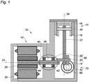
- the figure 1 shows in section a cooling device 10 implementing a thermodynamic cycle of the reverse Stirling type.
- the device comprises a compressor 12 driven by a rotary motor 14.
- the compressor 12 mainly comprises a reciprocating piston 16 moving in translation in a reciprocating movement in a cylinder 18.
- the piston 16 is driven by a crank pin 20 using a connecting rod 22.
- the crank pin 20 is rotated by the motor 14 around an axis 24.
- the motor 14 comprises a rotor 26 driving a motor shaft 28 integral with the crank pin 20.
- the assembly formed by the drive shaft 28 and the crank pin 20 is here designated crankshaft 46.
- the rotor 26 is disposed inside a stator 30.
- the cooling device 10 comprises a monobloc support 32.
- the support 32 is produced in a single mechanical part.
- the support 32 comprises a bore extending along an axis 34 perpendicular to the axis 24.
- the bore forms the cylinder 18 in which the piston 16 moves.
- a jacket 36 carried by the support 32 is interposed between the support 32 and the piston 16.
- the support 32 further comprises a housing 38 in which is located a bearing 40 supporting the crankshaft 46.
- the bearing 40 is disposed in the housing 38 without intermediate piece between the bearing 40 and the housing 38.
- the monobloc support 32 is advantageously produced without assembly.
- an assembly can be accepted provided that the bore forming the cylinder 18 as well as the housing 38 receiving the bearing 40 are machined after assembly. This machining carried out after assembly makes it possible to prevent the tolerances of the assembly from coming to cumulate with that connecting the cylinder 18 and the housing 38.
- one-piece means a mechanical part whose manufacturing tolerances are not not impacted by any assembly that may occur during its manufacturing process.
- having the bearing 40 in the support 32 without an intermediate part makes it possible to limit the dimension chains between the cylinder 18 and the crankshaft 46. No intermediate mechanical part whose dimensions would lengthen the dimension chain is located between the housing 38 and the bearing 40.
- the axis 24 is defined as the axis of rotation of the bearing 40.
- a single bearing 40 carries the rotating part of the cooling device 10 formed by the rotor 26 and the crankshaft 46. This single bearing 40 makes it possible to facilitate the production of the support 32. Indeed, it would be possible to support the rotating part by means of two bearings, for example located on either side of the crankshaft. However, this provision imposes tolerances of tight manufacturing to align the two bearings along axis 24. A single bearing avoids this alignment constraint.
- the housing 38 generally has a form of bore extending along the axis 24. In order to limit the overhang of the motor shaft, the housing 38 is located between the motor 14 and the crank pin 20. Alternatively, it is also possible to arrange the housing 38 and therefore the bearing 40 on the other side of the motor 14 or on the other side of the crank pin 20. However the position of the bearing 40 between the motor 14 and the crank pin 20 allows better distribution the loads supported by the bearing 40, exerted in particular by the compressor 12 and by the motor 14.
- the bearing 40 is for example formed of two bearings 42 and 44, the outer rings of which are integral with the housing 38 and the inner rings of which carry the motor shaft 28.
- the bearings 42 and 44 can be combined in the form, for example, of a bearing double row of rolling elements with a common outer ring and two separate inner rings in order to limit the clearances in the bearing 40 as much as possible.
- the bearings can be replaced by a plain bearing.
- the outer rings of the bearings 42 and 44 or the outer ring of the plain bearing can be fixed to the support 32 by means of a tight fit and / or adhesive placed between the outer ring (s) and the support 32. This adhesive does not constitute an intermediate mechanical part between the support 32 and the bearing 40.
- the outer ring of the plain bearing can be directly produced in the monobloc support 32.
- stator 30 of the motor 14 It is also possible to fix the stator 30 of the motor 14 directly on the support 32. This simplifies the dimension chain making it possible to define the functional clearance between the stator 30 and the rotor 26. This dimension chain only passes through the stator 30, support 32, bearing 40, the motor shaft 28 and the rotor 26. No other mechanical part belonging to the equivalence class of the support 32 appears in this chain of dimensions.
- the figure 2 represents the cooling device 10 in section in a plane perpendicular to the cutting plane of the figure 1 , that is to say perpendicular to the axis 24.
- the cooling device 10 further comprises a regenerator 70 also driven in rotation by the engine 14 and more precisely by the crankshaft 46.
- the regenerator is sometimes called displacer.
- the regenerator 70 mainly comprises a reciprocating piston 72 moving in translation in a reciprocating movement in a cylinder 74 along an axis 76.
- the axis 76 of the regenerator 70 is perpendicular to the axis 34 along which the piston 16 of the compressor 12 moves. It is also possible to produce a cooling device according to the invention with other relative orientations of the axes 76 and 34.
- the piston 72 is driven by the crank pin 20 using a connecting rod 78.
- the crankshaft 46 may include a second crank pin, distinct from the crank pin 20 and driving the connecting rod 78.
- the cylinder 74 is advantageously produced in the monobloc support 32.
- the support 32 comprises a bore forming the cylinder 74.
- the regenerator bore 70 is jacketed.
- a jacket 80 carried by the support 32, is interposed between the support 32 and the piston 72.
- the figure 3 shows a variant of the cooling device 10 in section in a plane similar to that of the figure 2 .
- the compressor 12 and the regenerator 70 In the support 32 there is the bore forming the cylinder 18 of the compressor 12 and the bore forming the cylinder 74 of the regenerator 70.
- the cylinders 18 and 74 of the support 32 are not lined and the pistons 16 and 72 slide in the support 32 without an intermediate mechanical part. More precisely, the only intermediary between a piston and its cylinder can be a fluid, a fluid or solid lubricant. It is possible to keep a jacket for only one of the pistons, either for the piston 16 or for the piston 72.
- the invention is already advantageous by eliminating at least one of the two shirts 36 or 80.
- the figure 4 shows another variant of the cooling device 10 shown in the figure 1 .
- compressor 12 the regenerator 70 and the engine 14.
- the support 32 there are the bores forming the cylinders 18 and 74 as well as the housing 38 in which the bearing 40 is disposed.
- the outer rings 48 of the bearings 42 and 44 are directly produced in the support 32.
- the housing 38 is more complicated to produce but in this variant, there is no longer any adjustment to be made between the outer rings of the bearings and the support 32.
- shirt 36 appears. It is of course possible to do without this shirt as shown on the figure 3 . It is the same for the shirt 80 which we can do without in the variant of the figure 4 .
- the figure 5 shows a second cooling device 50 implementing a thermodynamic cycle of the reverse Stirling type.
- the compressor 12 whose piston 16 is driven by the crankshaft 20.
- the jacket 36 serves as an intermediary between the bore of the support 52 and the piston 16. It is of course possible to do without the jacket 36 as described using figures 2 and 4 .
- a crankshaft 65 is driven by an electric motor 54 with an external rotor.
- the reciprocating movement of the pistons in their respective cylinders generates alternating and potentially phase-shifting axial forces. These forces, exerted by the pistons, are transmitted to the crank pin 20 by the connecting rods present in the cooling device 50.
- the combination of these loads results in a resistant torque of variable amplitude at the level of the motor shaft 64. More precisely , this couple presents strong amplitude variations between a value close to zero and a maximum value reached twice per revolution. It is possible to limit the impact of these resistive torque variations on the motorization using a flywheel added to the motor shaft.
- An external rotor motor has, by construction, a moment of inertia around its axis of rotation. more important than an internal rotor motor as described on figures 1 to 4 .
- the use of an external rotor motor therefore makes it possible to combine the functions carried by the rotor and the flywheel within the same component.
- an external rotor motor can generate a torque greater than that of an internal rotor motor.
- the use of an external rotor motor therefore makes it possible to facilitate the miniaturization of the cooling device.
- the stator 56 of the motor 54 has a cylindrical shape open along the axis of rotation 24 of the motor.
- the stator 56 comprises for example windings making it possible to generate a rotating magnetic field extending radially with respect to the axis 24 at the periphery of the stator 56.
- the motor 54 comprises a rotor 58 produced in the form of a tubular segment with an axis of revolution 24.
- the rotor 58 is arranged radially around the stator 56.
- the rotor 58 may comprise windings or permanent magnets intended to hang on the magnetic field generated by the stator windings.
- the use of permanent magnets makes it possible to avoid the use of rotating contacts, such as brushes or carbon brushes, necessary for supplying the rotor windings.
- the support 52 is in one piece like the support 32 and includes a tubular bearing 60 extending along the axis 24.
- the stator 56 is fixed on the outside of the tubular bearing 60 which passes through the stator 56.
- the interior of this bearing tubular 60 forms a housing 62 in which is located the bearing 40 supporting the motor shaft 64.
- the bearing 40 is formed of two bearings 42 and 44. As before, the outer rings of the bearings 42 and 44 can be produced directly in the support 52 and more precisely inside the bearing 60.
- bearings 42 and 44 can be replaced by other mechanical components such as plain bearings.
- the two bearings 42 and 44 of the device 50 can for example be combined into a double-row bearing of rolling elements with a common outer ring and two separate inner rings.
- the embodiment of the figure 5 allows to move the bearings 42 and 44 along the axis 24, ensuring better mechanical stability to the rotating parts of the cooling device 50.
- the bearings 42 and 44 can be ball or roller.
- the bearing contacts can be straight or oblique.
- the drive shaft 64 is secured to a veil 66 arranged perpendicular to the axis 24.
- the veil 66 is secured to a tube segment 68 of axis of revolution 24.
- the rotor 58 is fixed inside the segment of tube 68.
- the motor 54 is disposed between the support 52 and the web 66.
Landscapes
- Engineering & Computer Science (AREA)
- Mechanical Engineering (AREA)
- General Engineering & Computer Science (AREA)
- Chemical & Material Sciences (AREA)
- Combustion & Propulsion (AREA)
- Power Engineering (AREA)
- Physics & Mathematics (AREA)
- Thermal Sciences (AREA)
- Compressor (AREA)
- Compressors, Vaccum Pumps And Other Relevant Systems (AREA)
Priority Applications (1)
| Application Number | Priority Date | Filing Date | Title |
|---|---|---|---|
| SI201930059T SI3674626T1 (sl) | 2018-12-28 | 2019-12-24 | Hladilna naprava s stirlingovim ciklom z integralno montažo |
Applications Claiming Priority (1)
| Application Number | Priority Date | Filing Date | Title |
|---|---|---|---|
| FR1874268A FR3091338B1 (fr) | 2018-12-28 | 2018-12-28 | Dispositif de refroidissement à cycle Stirling inversé avec support monobloc |
Publications (2)
| Publication Number | Publication Date |
|---|---|
| EP3674626A1 true EP3674626A1 (de) | 2020-07-01 |
| EP3674626B1 EP3674626B1 (de) | 2021-04-07 |
Family
ID=67587804
Family Applications (1)
| Application Number | Title | Priority Date | Filing Date |
|---|---|---|---|
| EP19219632.7A Active EP3674626B1 (de) | 2018-12-28 | 2019-12-24 | Kühlvorrichtung mit stirlingzyklus und monoblockhalterung |
Country Status (6)
| Country | Link |
|---|---|
| US (1) | US11473815B2 (de) |
| EP (1) | EP3674626B1 (de) |
| CN (1) | CN111379689B (de) |
| FR (1) | FR3091338B1 (de) |
| IL (1) | IL271688B2 (de) |
| SI (1) | SI3674626T1 (de) |
Families Citing this family (2)
| Publication number | Priority date | Publication date | Assignee | Title |
|---|---|---|---|---|
| JP2024006514A (ja) * | 2022-07-04 | 2024-01-17 | マックス株式会社 | エアコンプレッサ |
| CN119573273A (zh) * | 2024-12-16 | 2025-03-07 | 安徽光智科技有限公司 | 一种斯特林制冷机 |
Citations (4)
| Publication number | Priority date | Publication date | Assignee | Title |
|---|---|---|---|---|
| US4365982A (en) | 1981-12-30 | 1982-12-28 | The United States Of America As Represented By The Secretary Of The Army | Cryogenic refrigerator |
| JPH08313093A (ja) * | 1995-05-19 | 1996-11-29 | Sanyo Electric Co Ltd | ガス圧縮膨張機の軸受への潤滑油供給装置 |
| EP0778452A1 (de) * | 1995-12-08 | 1997-06-11 | Cryotechnologies | Stirling-Kühlanlage mit Drehantrieb |
| JPH09170491A (ja) * | 1995-12-21 | 1997-06-30 | Sanyo Electric Co Ltd | 熱ガス機関 |
Family Cites Families (18)
| Publication number | Priority date | Publication date | Assignee | Title |
|---|---|---|---|---|
| US3074244A (en) * | 1961-04-12 | 1963-01-22 | Malaker Lab Inc | Miniature cryogenic engine |
| CN85100359B (zh) * | 1985-04-01 | 1988-12-14 | 黎正中 | 曲柄圆滑块往复活塞式压缩机 |
| US4796430A (en) * | 1987-08-14 | 1989-01-10 | Cryodynamics, Inc. | Cam drive for cryogenic refrigerator |
| US5056317A (en) * | 1988-04-29 | 1991-10-15 | Stetson Norman B | Miniature integral Stirling cryocooler |
| US4911618A (en) * | 1988-06-16 | 1990-03-27 | Mitsubishi Denki Kabushiki Kaisha | Cryocompressor with a self-centering piston |
| KR0175878B1 (ko) * | 1995-07-29 | 1999-10-01 | 윤종용 | 압축기용 크랭크 샤프트 지지구조 |
| DE69819730T2 (de) * | 1997-07-15 | 2004-09-30 | New Power Concepts Llc | Brennverfahren |
| CN2342328Y (zh) * | 1998-09-02 | 1999-10-06 | 李国富 | 改良斯特林循环制冷机的驱动机构 |
| US7269961B2 (en) * | 2005-07-22 | 2007-09-18 | Pendray John R | Thermodynamic cycle apparatus and method |
| DE102009011477A1 (de) * | 2009-03-06 | 2010-09-09 | Lichtblick - Die Zukunft Der Energie Gmbh & Co. Kg | Blockheizkraftwerk-Aggregat mit einem Verbrennungskolbenmotor und einer elektrischen Maschine |
| CH701391B1 (de) * | 2009-06-11 | 2011-01-14 | Mona Intellectual Property Establishment | Wärmeübertragungskolben sowie Wärmekraftmaschine mit Wärmeübertragungskolben. |
| CN102364100B (zh) * | 2011-11-11 | 2015-01-07 | 黄石东贝电器股份有限公司 | 一种制冷压缩机曲轴轴向止推轴承支承结构 |
| CN104410182B (zh) * | 2014-10-13 | 2017-05-24 | 三禾电器(福建)有限公司 | 一种电泵 |
| CN104564416B (zh) * | 2014-11-18 | 2016-01-20 | 西安交通大学 | 一种星型连杆传动的斯特林发动机 |
| CN105634184B (zh) * | 2016-03-18 | 2018-11-09 | 珠海格力电器股份有限公司 | 带旋转变压器的轴承组件及具有其的电机 |
| CN106050604A (zh) * | 2016-06-29 | 2016-10-26 | 武汉高德红外股份有限公司 | 旋转式双活塞压缩机以及斯特林制冷装置 |
| CN206144738U (zh) * | 2016-09-30 | 2017-05-03 | 瑞立集团瑞安汽车零部件有限公司 | 一种无油空压机传动机构 |
| CN207847936U (zh) * | 2017-12-30 | 2018-09-11 | 苏州工业园区泰格电子科技有限公司 | 一种新型变频涡旋式压缩机 |
-
2018
- 2018-12-28 FR FR1874268A patent/FR3091338B1/fr not_active Expired - Fee Related
-
2019
- 2019-12-24 SI SI201930059T patent/SI3674626T1/sl unknown
- 2019-12-24 IL IL271688A patent/IL271688B2/en unknown
- 2019-12-24 EP EP19219632.7A patent/EP3674626B1/de active Active
- 2019-12-27 CN CN201911374374.9A patent/CN111379689B/zh active Active
- 2019-12-27 US US16/728,770 patent/US11473815B2/en active Active
Patent Citations (4)
| Publication number | Priority date | Publication date | Assignee | Title |
|---|---|---|---|---|
| US4365982A (en) | 1981-12-30 | 1982-12-28 | The United States Of America As Represented By The Secretary Of The Army | Cryogenic refrigerator |
| JPH08313093A (ja) * | 1995-05-19 | 1996-11-29 | Sanyo Electric Co Ltd | ガス圧縮膨張機の軸受への潤滑油供給装置 |
| EP0778452A1 (de) * | 1995-12-08 | 1997-06-11 | Cryotechnologies | Stirling-Kühlanlage mit Drehantrieb |
| JPH09170491A (ja) * | 1995-12-21 | 1997-06-30 | Sanyo Electric Co Ltd | 熱ガス機関 |
Also Published As
| Publication number | Publication date |
|---|---|
| EP3674626B1 (de) | 2021-04-07 |
| FR3091338B1 (fr) | 2021-04-23 |
| IL271688B2 (en) | 2024-07-01 |
| FR3091338A1 (fr) | 2020-07-03 |
| IL271688A (en) | 2020-06-30 |
| CN111379689A (zh) | 2020-07-07 |
| CN111379689B (zh) | 2024-03-26 |
| US20200208884A1 (en) | 2020-07-02 |
| SI3674626T1 (sl) | 2021-06-30 |
| US11473815B2 (en) | 2022-10-18 |
| IL271688B1 (en) | 2024-03-01 |
Similar Documents
| Publication | Publication Date | Title |
|---|---|---|
| US10156186B2 (en) | Actuator for link mechanism for internal combustion engine, and method for assembling said actuator | |
| FR3129970A1 (fr) | Turbomachine comprenant une machine électrique en aval d’un arbre de turbine et entraînée par cet arbre | |
| EP3674626B1 (de) | Kühlvorrichtung mit stirlingzyklus und monoblockhalterung | |
| FR2371599A1 (fr) | Palier de tete de bielle de moteur | |
| EP2281107B1 (de) | Motor mit einem raum mit variablem volumen | |
| FR2498685A1 (fr) | Moteur a combustion interne a cylindres en v, perfectionne | |
| EP3674625B1 (de) | Kühlvorrichtung mit stirlingzyklus und motor mit externem rotor | |
| JP6589746B2 (ja) | 内燃機関用リンク機構のアクチュエータ | |
| JP6377272B2 (ja) | 内燃機関の可変圧縮比機構 | |
| FR2766539A1 (fr) | Arbre d'equilibrage pour un moteur a combustion interne | |
| FR3068444B1 (fr) | Dispositif de refroidissement destine a etre embarque dans un dispositif de vision infrarouge a double element deformable | |
| FR3096072A1 (fr) | Turbomachine comprenant un amortisseur de palier d’arbre à viscance variable | |
| EP1902795A1 (de) | Fahrzeugmotor mit rollengelagerter Kurbelwelle | |
| BE523269A (de) | ||
| JP6408095B2 (ja) | 可変圧縮比機構のアクチュエータ | |
| EP3478978B1 (de) | Vorrichtung zur bereitstellung einer drehkupplung zwischen einem motorschwungrad und einer kurbelwelle | |
| EP1533545B1 (de) | Automatisches Getriebe | |
| FR2822904A3 (fr) | Dispositif de demarrage | |
| EP3645951A1 (de) | Kühlvorrichtung zur ausstattung einer infrarotsichtvorrichtung mit einem verformbaren element | |
| BE400881A (de) | ||
| JP2019002520A (ja) | クランクシャフトの支持構造 | |
| BE366152A (de) | ||
| BE400882A (de) | ||
| BE533100A (de) | ||
| JPH10141444A (ja) | バランスシャフトの駆動機構 |
Legal Events
| Date | Code | Title | Description |
|---|---|---|---|
| PUAI | Public reference made under article 153(3) epc to a published international application that has entered the european phase |
Free format text: ORIGINAL CODE: 0009012 |
|
| STAA | Information on the status of an ep patent application or granted ep patent |
Free format text: STATUS: THE APPLICATION HAS BEEN PUBLISHED |
|
| AK | Designated contracting states |
Kind code of ref document: A1 Designated state(s): AL AT BE BG CH CY CZ DE DK EE ES FI FR GB GR HR HU IE IS IT LI LT LU LV MC MK MT NL NO PL PT RO RS SE SI SK SM TR |
|
| AX | Request for extension of the european patent |
Extension state: BA ME |
|
| STAA | Information on the status of an ep patent application or granted ep patent |
Free format text: STATUS: REQUEST FOR EXAMINATION WAS MADE |
|
| 17P | Request for examination filed |
Effective date: 20200825 |
|
| RBV | Designated contracting states (corrected) |
Designated state(s): AL AT BE BG CH CY CZ DE DK EE ES FI FR GB GR HR HU IE IS IT LI LT LU LV MC MK MT NL NO PL PT RO RS SE SI SK SM TR |
|
| GRAP | Despatch of communication of intention to grant a patent |
Free format text: ORIGINAL CODE: EPIDOSNIGR1 |
|
| STAA | Information on the status of an ep patent application or granted ep patent |
Free format text: STATUS: GRANT OF PATENT IS INTENDED |
|
| INTG | Intention to grant announced |
Effective date: 20201211 |
|
| GRAS | Grant fee paid |
Free format text: ORIGINAL CODE: EPIDOSNIGR3 |
|
| GRAA | (expected) grant |
Free format text: ORIGINAL CODE: 0009210 |
|
| STAA | Information on the status of an ep patent application or granted ep patent |
Free format text: STATUS: THE PATENT HAS BEEN GRANTED |
|
| AK | Designated contracting states |
Kind code of ref document: B1 Designated state(s): AL AT BE BG CH CY CZ DE DK EE ES FI FR GB GR HR HU IE IS IT LI LT LU LV MC MK MT NL NO PL PT RO RS SE SI SK SM TR |
|
| REG | Reference to a national code |
Ref country code: GB Ref legal event code: FG4D Free format text: NOT ENGLISH |
|
| REG | Reference to a national code |
Ref country code: AT Ref legal event code: REF Ref document number: 1380195 Country of ref document: AT Kind code of ref document: T Effective date: 20210415 Ref country code: CH Ref legal event code: EP |
|
| REG | Reference to a national code |
Ref country code: DE Ref legal event code: R096 Ref document number: 602019003780 Country of ref document: DE |
|
| REG | Reference to a national code |
Ref country code: IE Ref legal event code: FG4D Free format text: LANGUAGE OF EP DOCUMENT: FRENCH |
|
| REG | Reference to a national code |
Ref country code: LT Ref legal event code: MG9D |
|
| REG | Reference to a national code |
Ref country code: NL Ref legal event code: MP Effective date: 20210407 Ref country code: AT Ref legal event code: MK05 Ref document number: 1380195 Country of ref document: AT Kind code of ref document: T Effective date: 20210407 |
|
| PG25 | Lapsed in a contracting state [announced via postgrant information from national office to epo] |
Ref country code: NL Free format text: LAPSE BECAUSE OF FAILURE TO SUBMIT A TRANSLATION OF THE DESCRIPTION OR TO PAY THE FEE WITHIN THE PRESCRIBED TIME-LIMIT Effective date: 20210407 Ref country code: BG Free format text: LAPSE BECAUSE OF FAILURE TO SUBMIT A TRANSLATION OF THE DESCRIPTION OR TO PAY THE FEE WITHIN THE PRESCRIBED TIME-LIMIT Effective date: 20210707 Ref country code: AT Free format text: LAPSE BECAUSE OF FAILURE TO SUBMIT A TRANSLATION OF THE DESCRIPTION OR TO PAY THE FEE WITHIN THE PRESCRIBED TIME-LIMIT Effective date: 20210407 Ref country code: FI Free format text: LAPSE BECAUSE OF FAILURE TO SUBMIT A TRANSLATION OF THE DESCRIPTION OR TO PAY THE FEE WITHIN THE PRESCRIBED TIME-LIMIT Effective date: 20210407 Ref country code: HR Free format text: LAPSE BECAUSE OF FAILURE TO SUBMIT A TRANSLATION OF THE DESCRIPTION OR TO PAY THE FEE WITHIN THE PRESCRIBED TIME-LIMIT Effective date: 20210407 Ref country code: LT Free format text: LAPSE BECAUSE OF FAILURE TO SUBMIT A TRANSLATION OF THE DESCRIPTION OR TO PAY THE FEE WITHIN THE PRESCRIBED TIME-LIMIT Effective date: 20210407 |
|
| PG25 | Lapsed in a contracting state [announced via postgrant information from national office to epo] |
Ref country code: GR Free format text: LAPSE BECAUSE OF FAILURE TO SUBMIT A TRANSLATION OF THE DESCRIPTION OR TO PAY THE FEE WITHIN THE PRESCRIBED TIME-LIMIT Effective date: 20210708 Ref country code: IS Free format text: LAPSE BECAUSE OF FAILURE TO SUBMIT A TRANSLATION OF THE DESCRIPTION OR TO PAY THE FEE WITHIN THE PRESCRIBED TIME-LIMIT Effective date: 20210807 Ref country code: RS Free format text: LAPSE BECAUSE OF FAILURE TO SUBMIT A TRANSLATION OF THE DESCRIPTION OR TO PAY THE FEE WITHIN THE PRESCRIBED TIME-LIMIT Effective date: 20210407 Ref country code: SE Free format text: LAPSE BECAUSE OF FAILURE TO SUBMIT A TRANSLATION OF THE DESCRIPTION OR TO PAY THE FEE WITHIN THE PRESCRIBED TIME-LIMIT Effective date: 20210407 Ref country code: PT Free format text: LAPSE BECAUSE OF FAILURE TO SUBMIT A TRANSLATION OF THE DESCRIPTION OR TO PAY THE FEE WITHIN THE PRESCRIBED TIME-LIMIT Effective date: 20210809 Ref country code: NO Free format text: LAPSE BECAUSE OF FAILURE TO SUBMIT A TRANSLATION OF THE DESCRIPTION OR TO PAY THE FEE WITHIN THE PRESCRIBED TIME-LIMIT Effective date: 20210707 Ref country code: LV Free format text: LAPSE BECAUSE OF FAILURE TO SUBMIT A TRANSLATION OF THE DESCRIPTION OR TO PAY THE FEE WITHIN THE PRESCRIBED TIME-LIMIT Effective date: 20210407 Ref country code: PL Free format text: LAPSE BECAUSE OF FAILURE TO SUBMIT A TRANSLATION OF THE DESCRIPTION OR TO PAY THE FEE WITHIN THE PRESCRIBED TIME-LIMIT Effective date: 20210407 |
|
| REG | Reference to a national code |
Ref country code: DE Ref legal event code: R097 Ref document number: 602019003780 Country of ref document: DE |
|
| PG25 | Lapsed in a contracting state [announced via postgrant information from national office to epo] |
Ref country code: ES Free format text: LAPSE BECAUSE OF FAILURE TO SUBMIT A TRANSLATION OF THE DESCRIPTION OR TO PAY THE FEE WITHIN THE PRESCRIBED TIME-LIMIT Effective date: 20210407 Ref country code: EE Free format text: LAPSE BECAUSE OF FAILURE TO SUBMIT A TRANSLATION OF THE DESCRIPTION OR TO PAY THE FEE WITHIN THE PRESCRIBED TIME-LIMIT Effective date: 20210407 Ref country code: SK Free format text: LAPSE BECAUSE OF FAILURE TO SUBMIT A TRANSLATION OF THE DESCRIPTION OR TO PAY THE FEE WITHIN THE PRESCRIBED TIME-LIMIT Effective date: 20210407 Ref country code: CZ Free format text: LAPSE BECAUSE OF FAILURE TO SUBMIT A TRANSLATION OF THE DESCRIPTION OR TO PAY THE FEE WITHIN THE PRESCRIBED TIME-LIMIT Effective date: 20210407 Ref country code: DK Free format text: LAPSE BECAUSE OF FAILURE TO SUBMIT A TRANSLATION OF THE DESCRIPTION OR TO PAY THE FEE WITHIN THE PRESCRIBED TIME-LIMIT Effective date: 20210407 Ref country code: RO Free format text: LAPSE BECAUSE OF FAILURE TO SUBMIT A TRANSLATION OF THE DESCRIPTION OR TO PAY THE FEE WITHIN THE PRESCRIBED TIME-LIMIT Effective date: 20210407 Ref country code: SM Free format text: LAPSE BECAUSE OF FAILURE TO SUBMIT A TRANSLATION OF THE DESCRIPTION OR TO PAY THE FEE WITHIN THE PRESCRIBED TIME-LIMIT Effective date: 20210407 |
|
| PLBE | No opposition filed within time limit |
Free format text: ORIGINAL CODE: 0009261 |
|
| STAA | Information on the status of an ep patent application or granted ep patent |
Free format text: STATUS: NO OPPOSITION FILED WITHIN TIME LIMIT |
|
| 26N | No opposition filed |
Effective date: 20220110 |
|
| PG25 | Lapsed in a contracting state [announced via postgrant information from national office to epo] |
Ref country code: IS Free format text: LAPSE BECAUSE OF FAILURE TO SUBMIT A TRANSLATION OF THE DESCRIPTION OR TO PAY THE FEE WITHIN THE PRESCRIBED TIME-LIMIT Effective date: 20210807 Ref country code: AL Free format text: LAPSE BECAUSE OF FAILURE TO SUBMIT A TRANSLATION OF THE DESCRIPTION OR TO PAY THE FEE WITHIN THE PRESCRIBED TIME-LIMIT Effective date: 20210407 |
|
| PG25 | Lapsed in a contracting state [announced via postgrant information from national office to epo] |
Ref country code: MC Free format text: LAPSE BECAUSE OF FAILURE TO SUBMIT A TRANSLATION OF THE DESCRIPTION OR TO PAY THE FEE WITHIN THE PRESCRIBED TIME-LIMIT Effective date: 20210407 Ref country code: IT Free format text: LAPSE BECAUSE OF FAILURE TO SUBMIT A TRANSLATION OF THE DESCRIPTION OR TO PAY THE FEE WITHIN THE PRESCRIBED TIME-LIMIT Effective date: 20210407 |
|
| REG | Reference to a national code |
Ref country code: BE Ref legal event code: MM Effective date: 20211231 |
|
| PG25 | Lapsed in a contracting state [announced via postgrant information from national office to epo] |
Ref country code: LU Free format text: LAPSE BECAUSE OF NON-PAYMENT OF DUE FEES Effective date: 20211224 Ref country code: IE Free format text: LAPSE BECAUSE OF NON-PAYMENT OF DUE FEES Effective date: 20211224 |
|
| PG25 | Lapsed in a contracting state [announced via postgrant information from national office to epo] |
Ref country code: BE Free format text: LAPSE BECAUSE OF NON-PAYMENT OF DUE FEES Effective date: 20211231 |
|
| PG25 | Lapsed in a contracting state [announced via postgrant information from national office to epo] |
Ref country code: CY Free format text: LAPSE BECAUSE OF FAILURE TO SUBMIT A TRANSLATION OF THE DESCRIPTION OR TO PAY THE FEE WITHIN THE PRESCRIBED TIME-LIMIT Effective date: 20210407 |
|
| P01 | Opt-out of the competence of the unified patent court (upc) registered |
Effective date: 20230529 |
|
| PG25 | Lapsed in a contracting state [announced via postgrant information from national office to epo] |
Ref country code: HU Free format text: LAPSE BECAUSE OF FAILURE TO SUBMIT A TRANSLATION OF THE DESCRIPTION OR TO PAY THE FEE WITHIN THE PRESCRIBED TIME-LIMIT; INVALID AB INITIO Effective date: 20191224 |
|
| REG | Reference to a national code |
Ref country code: CH Ref legal event code: PL |
|
| PG25 | Lapsed in a contracting state [announced via postgrant information from national office to epo] |
Ref country code: LI Free format text: LAPSE BECAUSE OF NON-PAYMENT OF DUE FEES Effective date: 20221231 Ref country code: CH Free format text: LAPSE BECAUSE OF NON-PAYMENT OF DUE FEES Effective date: 20221231 |
|
| PG25 | Lapsed in a contracting state [announced via postgrant information from national office to epo] |
Ref country code: MK Free format text: LAPSE BECAUSE OF FAILURE TO SUBMIT A TRANSLATION OF THE DESCRIPTION OR TO PAY THE FEE WITHIN THE PRESCRIBED TIME-LIMIT Effective date: 20210407 |
|
| PG25 | Lapsed in a contracting state [announced via postgrant information from national office to epo] |
Ref country code: MT Free format text: LAPSE BECAUSE OF FAILURE TO SUBMIT A TRANSLATION OF THE DESCRIPTION OR TO PAY THE FEE WITHIN THE PRESCRIBED TIME-LIMIT Effective date: 20210407 |
|
| PG25 | Lapsed in a contracting state [announced via postgrant information from national office to epo] |
Ref country code: TR Free format text: LAPSE BECAUSE OF FAILURE TO SUBMIT A TRANSLATION OF THE DESCRIPTION OR TO PAY THE FEE WITHIN THE PRESCRIBED TIME-LIMIT Effective date: 20210407 |
|
| PGFP | Annual fee paid to national office [announced via postgrant information from national office to epo] |
Ref country code: DE Payment date: 20251119 Year of fee payment: 7 |
|
| PGFP | Annual fee paid to national office [announced via postgrant information from national office to epo] |
Ref country code: GB Payment date: 20251113 Year of fee payment: 7 |
|
| PGFP | Annual fee paid to national office [announced via postgrant information from national office to epo] |
Ref country code: FR Payment date: 20251124 Year of fee payment: 7 |
|
| PGFP | Annual fee paid to national office [announced via postgrant information from national office to epo] |
Ref country code: SI Payment date: 20251127 Year of fee payment: 7 |