EP3674638B1 - Kühlschrank - Google Patents
Kühlschrank Download PDFInfo
- Publication number
- EP3674638B1 EP3674638B1 EP19217526.3A EP19217526A EP3674638B1 EP 3674638 B1 EP3674638 B1 EP 3674638B1 EP 19217526 A EP19217526 A EP 19217526A EP 3674638 B1 EP3674638 B1 EP 3674638B1
- Authority
- EP
- European Patent Office
- Prior art keywords
- elevation
- plate
- drawer
- curved rack
- elevation plate
- Prior art date
- Legal status (The legal status is an assumption and is not a legal conclusion. Google has not performed a legal analysis and makes no representation as to the accuracy of the status listed.)
- Active
Links
Images


Classifications
-
- F—MECHANICAL ENGINEERING; LIGHTING; HEATING; WEAPONS; BLASTING
- F25—REFRIGERATION OR COOLING; COMBINED HEATING AND REFRIGERATION SYSTEMS; HEAT PUMP SYSTEMS; MANUFACTURE OR STORAGE OF ICE; LIQUEFACTION SOLIDIFICATION OF GASES
- F25D—REFRIGERATORS; COLD ROOMS; ICE-BOXES; COOLING OR FREEZING APPARATUS NOT OTHERWISE PROVIDED FOR
- F25D11/00—Self-contained movable devices, e.g. domestic refrigerators
- F25D11/02—Self-contained movable devices, e.g. domestic refrigerators with cooling compartments at different temperatures
-
- A—HUMAN NECESSITIES
- A47—FURNITURE; DOMESTIC ARTICLES OR APPLIANCES; COFFEE MILLS; SPICE MILLS; SUCTION CLEANERS IN GENERAL
- A47B—TABLES; DESKS; OFFICE FURNITURE; CABINETS; DRAWERS; GENERAL DETAILS OF FURNITURE
- A47B45/00—Cabinets, racks or shelf units, characterised by features enabling enlarging in height, length, or depth
-
- A—HUMAN NECESSITIES
- A47—FURNITURE; DOMESTIC ARTICLES OR APPLIANCES; COFFEE MILLS; SPICE MILLS; SUCTION CLEANERS IN GENERAL
- A47B—TABLES; DESKS; OFFICE FURNITURE; CABINETS; DRAWERS; GENERAL DETAILS OF FURNITURE
- A47B88/00—Drawers for tables, cabinets or like furniture; Guides for drawers
- A47B88/40—Sliding drawers; Slides or guides therefor
- A47B88/453—Actuated drawers
- A47B88/457—Actuated drawers operated by electrically-powered actuation means
-
- F—MECHANICAL ENGINEERING; LIGHTING; HEATING; WEAPONS; BLASTING
- F25—REFRIGERATION OR COOLING; COMBINED HEATING AND REFRIGERATION SYSTEMS; HEAT PUMP SYSTEMS; MANUFACTURE OR STORAGE OF ICE; LIQUEFACTION SOLIDIFICATION OF GASES
- F25D—REFRIGERATORS; COLD ROOMS; ICE-BOXES; COOLING OR FREEZING APPARATUS NOT OTHERWISE PROVIDED FOR
- F25D23/00—General constructional features
- F25D23/02—Doors; Covers
- F25D23/021—Sliding doors
-
- F—MECHANICAL ENGINEERING; LIGHTING; HEATING; WEAPONS; BLASTING
- F25—REFRIGERATION OR COOLING; COMBINED HEATING AND REFRIGERATION SYSTEMS; HEAT PUMP SYSTEMS; MANUFACTURE OR STORAGE OF ICE; LIQUEFACTION SOLIDIFICATION OF GASES
- F25D—REFRIGERATORS; COLD ROOMS; ICE-BOXES; COOLING OR FREEZING APPARATUS NOT OTHERWISE PROVIDED FOR
- F25D25/00—Charging, supporting, and discharging the articles to be cooled
- F25D25/005—Charging, supporting, and discharging the articles to be cooled using containers
-
- F—MECHANICAL ENGINEERING; LIGHTING; HEATING; WEAPONS; BLASTING
- F25—REFRIGERATION OR COOLING; COMBINED HEATING AND REFRIGERATION SYSTEMS; HEAT PUMP SYSTEMS; MANUFACTURE OR STORAGE OF ICE; LIQUEFACTION SOLIDIFICATION OF GASES
- F25D—REFRIGERATORS; COLD ROOMS; ICE-BOXES; COOLING OR FREEZING APPARATUS NOT OTHERWISE PROVIDED FOR
- F25D25/00—Charging, supporting, and discharging the articles to be cooled
- F25D25/02—Charging, supporting, and discharging the articles to be cooled by shelves
- F25D25/024—Slidable shelves
- F25D25/025—Drawers
-
- F—MECHANICAL ENGINEERING; LIGHTING; HEATING; WEAPONS; BLASTING
- F25—REFRIGERATION OR COOLING; COMBINED HEATING AND REFRIGERATION SYSTEMS; HEAT PUMP SYSTEMS; MANUFACTURE OR STORAGE OF ICE; LIQUEFACTION SOLIDIFICATION OF GASES
- F25D—REFRIGERATORS; COLD ROOMS; ICE-BOXES; COOLING OR FREEZING APPARATUS NOT OTHERWISE PROVIDED FOR
- F25D25/00—Charging, supporting, and discharging the articles to be cooled
- F25D25/02—Charging, supporting, and discharging the articles to be cooled by shelves
- F25D25/028—Cooled supporting means
-
- F—MECHANICAL ENGINEERING; LIGHTING; HEATING; WEAPONS; BLASTING
- F25—REFRIGERATION OR COOLING; COMBINED HEATING AND REFRIGERATION SYSTEMS; HEAT PUMP SYSTEMS; MANUFACTURE OR STORAGE OF ICE; LIQUEFACTION SOLIDIFICATION OF GASES
- F25D—REFRIGERATORS; COLD ROOMS; ICE-BOXES; COOLING OR FREEZING APPARATUS NOT OTHERWISE PROVIDED FOR
- F25D29/00—Arrangement or mounting of control or safety devices
- F25D29/005—Mounting of control devices
-
- A—HUMAN NECESSITIES
- A47—FURNITURE; DOMESTIC ARTICLES OR APPLIANCES; COFFEE MILLS; SPICE MILLS; SUCTION CLEANERS IN GENERAL
- A47B—TABLES; DESKS; OFFICE FURNITURE; CABINETS; DRAWERS; GENERAL DETAILS OF FURNITURE
- A47B88/00—Drawers for tables, cabinets or like furniture; Guides for drawers
- A47B88/90—Constructional details of drawers
- A47B2088/901—Drawers having a lifting mechanism
-
- A—HUMAN NECESSITIES
- A47—FURNITURE; DOMESTIC ARTICLES OR APPLIANCES; COFFEE MILLS; SPICE MILLS; SUCTION CLEANERS IN GENERAL
- A47B—TABLES; DESKS; OFFICE FURNITURE; CABINETS; DRAWERS; GENERAL DETAILS OF FURNITURE
- A47B2210/00—General construction of drawers, guides and guide devices
- A47B2210/17—Drawers used in connection with household appliances
- A47B2210/175—Refrigerators or freezers
-
- F—MECHANICAL ENGINEERING; LIGHTING; HEATING; WEAPONS; BLASTING
- F25—REFRIGERATION OR COOLING; COMBINED HEATING AND REFRIGERATION SYSTEMS; HEAT PUMP SYSTEMS; MANUFACTURE OR STORAGE OF ICE; LIQUEFACTION SOLIDIFICATION OF GASES
- F25D—REFRIGERATORS; COLD ROOMS; ICE-BOXES; COOLING OR FREEZING APPARATUS NOT OTHERWISE PROVIDED FOR
- F25D2400/00—General features of, or devices for refrigerators, cold rooms, ice-boxes, or for cooling or freezing apparatus not covered by any other subclass
- F25D2400/18—Aesthetic features
-
- F—MECHANICAL ENGINEERING; LIGHTING; HEATING; WEAPONS; BLASTING
- F25—REFRIGERATION OR COOLING; COMBINED HEATING AND REFRIGERATION SYSTEMS; HEAT PUMP SYSTEMS; MANUFACTURE OR STORAGE OF ICE; LIQUEFACTION SOLIDIFICATION OF GASES
- F25D—REFRIGERATORS; COLD ROOMS; ICE-BOXES; COOLING OR FREEZING APPARATUS NOT OTHERWISE PROVIDED FOR
- F25D2400/00—General features of, or devices for refrigerators, cold rooms, ice-boxes, or for cooling or freezing apparatus not covered by any other subclass
- F25D2400/36—Visual displays
-
- F—MECHANICAL ENGINEERING; LIGHTING; HEATING; WEAPONS; BLASTING
- F25—REFRIGERATION OR COOLING; COMBINED HEATING AND REFRIGERATION SYSTEMS; HEAT PUMP SYSTEMS; MANUFACTURE OR STORAGE OF ICE; LIQUEFACTION SOLIDIFICATION OF GASES
- F25D—REFRIGERATORS; COLD ROOMS; ICE-BOXES; COOLING OR FREEZING APPARATUS NOT OTHERWISE PROVIDED FOR
- F25D25/00—Charging, supporting, and discharging the articles to be cooled
- F25D25/04—Charging, supporting, and discharging the articles to be cooled by conveyors
Definitions
- the present disclosure relates to a refrigerator.
- refrigerators are home appliances for storing food at a low temperature in a storage space that is covered by a door.
- the refrigerators cool the inside of the storage space by using cool air generated by being heat-exchanged with a refrigerant circulated through a refrigeration cycle to store food in an optimum state.
- Such a refrigerator is becoming larger and multifunctioned as dietary changes and user's preferences become more diverse, and thus, a refrigerator having various structures and convenience devices for user's convenience and freshness of stored food has been introduced.
- the storage space of the refrigerator may be opened/closed by the door.
- refrigerators may be classified into various types according to an arranged configuration of the storage space and a structure of the door that opens and closes the storage space.
- the refrigerator door may be classified into a rotation-type door that opens and closes a storage space through rotation thereof and a drawer-type door that is inserted and withdrawn in a drawer like manner.
- the drawer-type door is often disposed in a lower region of the refrigerator.
- a user has to turn their back to take out a basket or food in the drawer-type door. If the basket or the food is heavy, the user may feel inconvenient to use the drawer-type door or may be injured.
- a refrigerator provided with a lifting mechanism for elevating a storage box provided in a refrigerating compartment is disclosed in Korean Patent Publication No. 2006-0006321 (January 19, 2006 ).
- the lifting mechanism for the elevation is disposed outside the storage box, and thus is exposed. This may cause serious safety problems. In addition, the lifting mechanism may become contaminated due to the lifting mechanism being exposed to the outside.
- noise during operation of the driving part may be transmitted to the outside as is, which may cause the user's dissatisfaction.
- an upper end of the frame may protrude further upward than an upper end of the door.
- an elevation height of the storage box may be limited.
- WO 2010/099037 A2 discloses a refrigerator that includes a compartment, a first container, a second container, a door, and a selection device.
- the first container and the second container are located in the compartment and configured to be movable in a first direction.
- the door is operably connected to the second container and configured to provide access to at least one of the first container and the second container of the compartment when the door is moved to an open position.
- the selection device is located on the refrigerator and configured for inputting a selection of either the first container or the second container.
- the selected container is presented in an accessible position when the door is moved from the closed position to the open position.
- WO2013/098257 A1 shows a cooling device comprising a body having two opposite side walls, at least one shelf whereon the items are placed, that can be at a higher position and a lower position, at different heights from each other and at least one height adjustment mechanism that provides the height of the shelf to be changed.
- EP 3 040 664 A2 discloses a refrigerator including a movable body disposed in an inner case, the inner case defining a storage compartment therein, a shelf connected to the movable body via a connection member, and a guard configured to surround an edge of the shelf, the guard having a size greater than the size of the shelf, the guard being provided with a protrusion member protruding toward the movable body, wherein the movable body is provided with a guide rail configured to guide the sliding movement of the protrusion member.
- FR 2 614 514 A1 shows a movable support for electric household appliances intended to be fixed in pieces of furniture.
- the movable support comprises a top for receiving an appliance and an electromechanical device for driving the top in such a way as to bring the appliance either into a storage position or into a use position.
- the electromechanical device comprises a motor unit attached to a base and capable of driving two pairs of levers which are on the one hand connected to the top and on the other hand to the base by means of small wheels.
- CN 107 062 761 A discloses an air outlet control structure of an air duct and an air-cooled refrigerator.
- the air duct comprises two air outlets, the size of their openings being controlled by the air outlet control structure.
- the air outlet control structure comprises two sliding blocks connected to a power assembly, wherein the two sliding blocks are arranged at the two air outlets in a sliding mode and used for controlling the sizes of the openings.
- Embodiments provide a refrigerator including an elevation plate disposed in a storage box and an elevation device configured to allow the elevation plate to move vertically.
- the elevation device includes a driving motor, a curved rack that rotates by receiving driving force of the driving motor and is curved at a predetermined curvature, and an elevation bar configured to connect the curved rack to the elevation plate.
- the elevation bar allows the elevation plate to ascend or descend while moving along a rotation trajectory of the curved rack together with the curved rack.
- a plate support device may be connected to the elevation plate so that the elevation plate is elevated while being maintained in a horizontal state.
- a refrigerator comprises a cabinet having a storage space therein; and a drawer slidably movable forward and backward from the storage space, the drawer comprising a door; a storage box provided at a rear surface of the door; an elevation plate disposed within the storage box; and an elevation device connected with one side of the elevation plate to lift (i.e. vertically elevate) the elevation plate, wherein the elevation device comprises a driving motor; a curved rack to rotate by a rotational force generated by the driving motor, the curved rack being curved at a predetermined curvature; and an elevation bar to connect the curved rack with the elevation plate, the elevation bar to rotate together with the curved rack to lift (i.e. ascend) and lower (i.e. descend) the elevation plate.
- the elevation plate may have a rectangular plate shape.
- a A first and second elevation bar may engage with the elevation plate at opposite corners along one edge thereof.
- the curved rack may comprise a circular rack or an arc-shaped rack.
- a rotation axis of the curved rack may be disposed corresponding to a center portion or a vertical centerline of the elevation plate. That is, the elevation device may be disposed at or within a door of the drawer, and the rotation axis of the curved rack may correspond to a center of the door.
- the refrigerator may further comprise a driving gear gear-connected to the curved rack to rotate the curved rack.
- a gear part may be disposed at an inner circumferential surface or an outer circumferential surface of the curved rack.
- the driving gear may be engaged with the gear part.
- the refrigerator may further comprise a reduction gear connected with a shaft of the driving motor to reduce a rotational rate or a rotational speed of the driving motor.
- the driving gear may be connected with a driving shaft of the reduction gear.
- the elevation device may be accommodated at or within the door.
- the elevation bar may pass through a rear surface of the door to connect with the one side of the elevation plate.
- a rear surface may denote a surface of the door facing the storage space or the elevation plate.
- a front end of the elevation plate may denote an end or edge facing the door
- a rear end of the elevation plate may denote an end or edge opposite to the front end, i.e. facing away from the door.
- a front direction may denote the direction of withdrawal of the drawer out of the storage space.
- a rear direction may denote the direction of insertion of the drawer into the storage space.
- An arc-shaped guide slit to guide movement of the elevation bar may be disposed at the rear surface of the door.
- the elevation bar may move vertically in an arc to ascend or descend the elevation plate. As the elevation bar ascends or descends the elevation bar, the elevation may traverse in a left and right direction with respect to the elevation plate.
- the refrigerator may further comprise an idle gear mounted at an end of the elevation bar.
- a gear part may be disposed at a bottom surface of the elevation plate.
- the idle gear may be engaged with the gear part.
- a guide groove to guide movement of the idle gear may be disposed at a front surface of the elevation plate.
- the gear part may be disposed at the guide groove.
- the refrigerator may further comprise a plate support device to support the elevation plate to maintain a horizontal state while the elevation plate ascends and descends.
- the plate support device may comprise a rail assembly to connect a side surface of the elevation plate with a side surface of the storage box.
- the rail assembly may comprise a fixed rail connected with the side surface of the storage box; and a movable rail connected with the side surface of the elevation plate and movably connected with the fixed rail.
- the refrigerator may further comprise a rotation plate having an elevation bar insertion hole through which the elevation bar is inserted.
- a rotation plate mounting hole into which the rotation plate is inserted may be disposed at the rear surface of the door.
- the rotation plate may cover the arc-shaped guide slit.
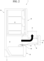
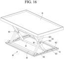
- the drawer 30 may be designed to move into and out of the cabinet 10 or of the storage space 12, i.e. horizontally forward and backward by a draw-out motor (not shown) and a pinion 141, which are provided in the cabinet 10, and a draw-out rack 34 or a rail, which is provided at a bottom surface of the drawer 30. Also, the operation command of the draw-out motor may be inputted through any one or all of the manipulation parts 22 and 301.
- the drawer 30 may be designed to continuously perform a horizontal sliding operation and a vertical elevating operation through a single draw-out command.
- the food may be directly placed on the elevation plate 34 so as to be stored.
- a separate storage case 33 may be provided at the storage box 32 so that the food is placed in the separate storage case 33, which is placed on the elevation plate 34.
- a guide slit 311 having an arc shape may be disposed at the rear surface of the sliding door 31, and an elevation bar to be described later may be inserted into the guide slit 311.
- the elevation bar included in the elevation device 50 may pass through the rear surface of the sliding door 31 and may be connected to the elevation plate 34.
- the elevation bar may move vertically along the guide slit 311 to allow the elevation plate 34 to move vertically.
- An elevation manipulation part 303 for inputting command to drive the elevation device 50 may be disposed at a top surface of the sliding door 31.
- the elevation manipulation part may include a touch type or button type input part and a display part. When the input part provided at the elevation manipulation part 303 is touched or pressed, the forward and backward movement and the elevation operation may be continuously performed, or only the elevation operation may be performed.
- a control program may be designed so that a drawer manipulation part 301 provided at the front surface of the sliding door 31 is manipulated to maximally withdraw the drawer 30 forward, and then, the elevation manipulation part 303 is manipulated to allow the elevation plate 34 to ascend.
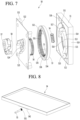
- FIG. 5 is a front perspective view of the elevation device according to an embodiment
- FIG. 6 is an exploded perspective view of the elevation device when viewed from a rear side
- FIG. 7 is an exploded perspective view of the elevation device when viewed from a front side.
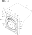
- the elevation device 50 includes a housing 51, a spring 54, an elevation bar 55, a curved rack 53, a driving gear 56, a cover 52, a driving motor 57, and a reduction gear 58.
- the sliding door 31 includes a front surface part exposed to the outside, a rear surface part as an opposite surface of the front surface part, and an edge part connecting the front surface part to the rear surface part.
- the edge part includes a top surface, a bottom surface, a left surface, and a right surface.
- the rear surface part of the sliding door 31 includes a first surface and a second surface.
- the first surface may be a surface which closely contacts the rear surface of the elevation device 50, and the second surface may be the front surface of the storage box 32.
- a front surface of the housing 51 is opened and covered by the cover 52, and a rear surface closely contacts the first surface of the rear surface part of the sliding door 31.
- a side wall 519 extends at an edge of the housing 51, and the cover 52 is connected to a front end of the side wall 519.
- the side wall 519 may be disposed on the housing 51, but may be disposed on an edge of the cover 52.
- An arc-shaped guide slit 511 is disposed at the rear surface of the housing 51. The guide slit 511 may be aligned with the guide slit 311 disposed at the rear surface part of the sliding door 31.
- a support boss 518 and a coupling boss may protrude from a front corner point of the housing 51.
- the support boss 518 and the coupling boss may be disposed at four corners of the front surface of the housing 51, respectively.
- An outer sleeve 512 surrounding an outer circumferential surface of the curved rack 53 may extend from the front surface of the housing 51.
- the outer sleeve 512 may extend by a length corresponding to an extension length (or width) of the side wall 519.
- the outer sleeve 512 may have a cylindrical shape that surrounds the curved rack 53.
- a center mount 513 may protrude from the front surface of the housing 51 corresponding to the inside of the outer sleeve 512.
- a distance between an outer edge of the center mount 513 and the outer sleeve 512 may correspond to a radial width of the curved rack 53.
- a space between the center mount 513 and the outer sleeve 512 may be defined as a curved rack mounting part 510 on which the curved rack 53 is mounted.
- the guide slit 511 may be disposed in the curved rack mounting part 510.
- a spring seating part 514 may be disposed at an edge of the center mount 513 at a predetermined depth in a central direction of the center mount 513 and may extend by a predetermined length in a circumferential direction.
- the spring seating part 514 may be rounded at a predetermined curvature.
- One end of the spring seating part 514 may include a shoulder 515, and a rack stopper 517 may extend from the other end of the spring seating part 514 in the circumferential direction of the center mount 513.
- a driving gear accommodation part 516 may be provided at an edge of the center mount 513, which corresponds to an opposite side of the spring seating part 514.
- the driving gear accommodation part 516 may be provided by cutting a portion of the center mount 513 in the central direction.
- the driving gear accommodation part 516 may be rounded at the same curvature as the driving gear 516 to accommodate a portion of a circumferential surface of the driving gear 56.
- the spring 54 may be accommodated in the spring seating part 514. As illustrated in the drawings, the spring is a coil spring.
- the curved rack 53 may have a circular ring shape being hollow therein.
- the curved rack 53 includes an outer rim 534 having a width corresponding to a width of the outer sleeve 512, an inner rim surrounding an inside of the outer rim 534 and having the same width as the outer rim 534, and a connection rim 537 connecting a rear end of the outer rim 534 to a rear end of the inner rim 535.
- a guide groove 536 may be disposed between the outer rim 534 and the inner rim 535.
- a gear part 531 may be disposed at an inner circumferential surface of the inner rim 535, and a spring pressing rib 532 may protrude from one side of the inner circumferential surface of the inner rim 535.
- the spring pressing rib 532 may have a width corresponding to the width of the inner rim 535 and may extend by a predetermined length in the central direction of the curved rack 53.
- An elevation bar mounting part 533 may be provided in the form of a hole or groove at one side of the connection rim 537, and one end of the elevation bar 55 may be fitted into the elevation bar mounting part 533.
- the elevation bar 55 may sequentially pass through the guide slits 511 and 311 and may be connected to the elevation plate 34.
- each of the guide slits 511 and 311 may have a width corresponding to an outer diameter of the elevation bar 55.
- One surface of the spring pressing rib 532 may support one end of the spring 54.
- the spring 54 When the spring 54 extends maximally, the spring 54 may closely contact the shoulder 515. That is, when the curved rack 53 rotates, the spring pressing rib 532 moves in the circumferential direction within the spring seating part 514.
- the driving gear 56 may be accommodated in the driving gear accommodation part 516 and may engage with the gear part 531 of the inner circumferential surface to rotate the curved rack 53. Otherwise, the driving gear 56 may be engaged with the gear part 538 of the outer circumferential surface.
- the reduction gear 58 may be seated at a front surface of the cover 52.
- a reduction gear support rib 525 extending along an outer edge of the reduction gear 58 may be disposed at the front surface of the cover 52.
- a driving shaft hole 524 may be disposed at the cover 52 corresponding to the inside of the reduction gear support rib 525, and a driving shaft 581 extending from the reduction gear 58 may pass through the driving shaft hole 524 and may be connected to a center of the driving gear 56.
- An arc-shaped rack guide 523 may extend from the rear surface of the cover 52, and the rack guide 523 may be fitted into the guide groove 536 of the curved rack 53. Both ends of the rack guide 523 may extend up to both ends of the guide slit 511, respectively.
- the rack guide 523 may have a circular sleeve shape.
- the coupling boss 521 and the support boss 522 may extend from the corner portion of the rear surface of the cover 52.
- the coupling boss 521 and the support boss 522 may be coupled to the coupling boss and the support boss 518, which extend from the front surface of the housing 51.
- the support boss 522 may be fitted into an outer circumferential surface of the support boss 518 of the housing 51 to allow the cover 52 to be coupled to the housing 51 without being shaken.
- the coupling boss 521 in a state in which the coupling boss 521 closely contacts the front surface of the housing 51, the coupling boss 521 may be coupled to the coupling boss through a coupling member.
- the driving motor 57 and the reduction gear 58 may be modular coupled by a coupling bracket.
- FIG. 8 is a view illustrating a connection structure between the elevation plate and the elevation bar according to an embodiment.
- a guide gear 342 may be disposed at the bottom surface of the elevation plate 34, and an idle gear 551 may be mounted at the other end of the elevation bar 55.
- one end of the elevation bar 55 is connected to the curved rack 53, and the idle gear 551 is engaged with the guide gear 342.
- FIG. 9 is a view illustrating a connection structure between an elevation plate and an elevation bar according to another embodiment.
- an elevation bar having a U shape with a wide width may be disposed at a bottom surface of the front end of the elevation plate 34.
- an elevation bar 55 is inserted into a space defined by an elevation bar guide 341.
- the elevation bar 55 moves in left and right directions within the elevation bar guide 341 to allow an elevation plate to move vertically.
- An outer circumferential surface of the elevation bar 55 slidably moves in a state of contacting a bottom surface of the elevation plate 34.
- an idle gear may be connected to the other end of the elevation bar 55, and a guide gear may be disposed at the bottom surface of the elevation plate 34 corresponding to the inside of the elevation bar guide 341.
- FIG. 10 is a view illustrating a connection structure between an elevation plate and an elevation bar according to another embodiment.
- a guide groove 343 may be disposed at a front surface of an elevation plate 34, and the other end of an elevation bar 55 is fitted into the guide groove 343.
- the elevation plate 34 and the elevation bar 55 may be connected to each other.
- left and right lengths of the guide grooves 343 may correspond to a movement displacement in left and right directions of the elevation bar 55.
- An idle gear 551 is disposed at the other end of the elevation bar 55.
- the idle gear 551 may be inserted into the guide groove 343.
- the guide gear 344 may be disposed at a top surface of the guide groove 343 so as to engaged with the idle gear 551.
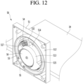
- FIG. 13 is a rear view of the elevation device when the elevation plate is disposed at the highest height in the state in which the drawer is removed
- FIG. 14 is a view illustrating a state of the inside of the elevation device when the elevation plate is disposed at the highest height.
- a plate support device 60 supporting the elevation plate 34 to maintain a horizontal state may be coupled to the bottom surface of the elevation plate 34.
- the plate support device 60 may include a lower frame 61, an upper frame 62, and a pair of scissor links 63.
- each of the lower frame 61 and the upper frame 62 may be a rectangular frame having a size corresponding to a planar shape of the elevation plate 34.
- the pair of scissor links 63 may be provided at left and right edges of the elevation plate 34, respectively.
- Each of the pair of scissor links 63 may include a first link 631 and a second link 632 that cross each other in an X shape. Also, a connector 68 may be inserted into a crossing point of the first link 631 and the second link 632. Here, the connector 68 may serve as a rotation center of the first link 631 and the second link 632.
- the left scissor link 63 may be defined as a left first link and a left second link, and the right scissor link 63 may be defined as a right first link and a right second link.
- Rear ends of the two first links and the rear ends of the two second links may be connected to each other by movable bars 65 and 67, respectively.
- the rear ends of the left and right first links are connected to each other by the first movable bar 67
- the rear ends of the left and right second links are connected to each other by the second movable bar 65.
- the first movable bar 67 is disposed to be movable forward and backward at the bottom surface of the upper frame 62, and the second movable bar 65 is disposed to be movable forward and backward direction at the top surface of the lower frame 61.
- the first fixed bar 64 may be fixed to the lower frame 61 by a lower holder 611
- the second fixed bar 66 may be fixed to the upper frame 62 by an upper holder 621.
- Each of the lower holder 611 and the upper holder 621 may be rounded or bent to cover the fixed bars 64 and 66, and both ends thereof may closely contact the lower frame 61 and the upper frame 62.
- both ends of the lower holder 611 and the upper holder 621 may be fixed to the lower frame 61 and the upper frame 62 by coupling members, respectively.
- the first movable bar 67 may be movably connected to a bottom surface of the upper frame 62 by an upper guide 622, and the second movable bar 65 may be movably connected to a top surface of the lower frame by a lower guide 612.
- Each of the upper guide 622 and the lower guide 612 may include a bent part that is bent in an n shape and a contact part that is bent again from both ends of the bent part to the outside to respectively closely contact the upper frame 62 and the lower frame 61.
- An upper guide space 623 and a lower guide space 613 are disposed between a top surface of the bent part and a bottom surface of the upper frame 61 or a top surface of the lower frame 61, respectively. Ends of the first movable bar 67 and the second movable bar 65 are inserted to move forward and backward, respectively.
- the movable bars 65 and 67 While the elevation plate 34 ascends by the operation of the elevation device 50, the movable bars 65 and 67 slidably move in a direction that is closer to the fixed bars 64 and 66, that is, in the forward direction. Then, when the elevation plate 34 reaches the highest point, the movable bars 65 and 67 are disposed at the front ends of the guide spaces 613 and 623.
- the movable bars 65 and 67 slidably move in a direction that is away from the fixed bars 64 and 66, that is, in the backward direction. Then, when the elevation plate 34 reaches the lowest point, the movable bars 65 and 67 are disposed at the rear ends of the guide spaces 613 and 623.
- the scissor link 63 is connected to each of the left and right edges of the elevation plate 34, the elevation plate 34 may ascend or descend while maintaining the horizontal state even though the single elevation device 50 is connected to the elevation plate 34.
- the plate support device 60 is disposed inside the storage box 32, the plate support device 60 is not exposed to the outside when the elevation plate 34 moves vertically. Thus, possibility of introduction of foreign substances into the plate support device 60 may be minimized, and also, possibility of user's injury due to catching of the user's clothing or body parts into the scissor link 63 may be prevented.
- the plate support device 60 may be disposed at the rear end of the elevation plate, one end of the scissor link 63 may be disposed at the left edge of the elevation plate, and the other end may be disposed at the right edge of the elevation plate.
- a center of the scissor link 63 may only vertically move at the center of the rear end of the elevation plate, and both ends of the scissor link 63 may move in the left and right directions.
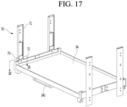
- FIG. 17 is a perspective view of an elevation plate provided with a support device according to another embodiment
- FIG. 18 is a transverse cross-sectional view taken along line 18-18 of FIG. 17 .
- a plate support device 70 having a form of a rail and supporting left and right surfaces of an elevation plate 34 is proposed.
- the plate support device 70 may be mounted at front and rear ends of the left and right surfaces and front and rear ends of the left and right surfaces of the elevation plate 34, respectively.
- the plate support device 70 may also have a structure in which the plate support device 70 is disposed at each of centers of the left and right surfaces of the elevation plate.
- the plate support device 70 may include a fixed rail 71 fixed to an inner surface of a sidewall of a storage box 32, a rail base 72 fixed to a side surface of the elevation plate 34, and a movable rail 73 movably fixed to the rail base 72.
- the rail base 72 may not be separately provided, and the movable rail 73 may be directly fixed to the side surface of the elevation plate 34.
- the movable rail 73 is disposed to be movable vertically along the fixed rail 72 in a state of being inserted into the fixed rail 72.
- the elevation plate 34 may be symmetrically disposed at a position with respect to a vertical surface that bisects the elevation plate into left and right portions so that the elevation plate 34 stably moves vertically while being maintained in the horizontal state.
- FIG. 19 is a rear perspective view of the curved rack according to another embodiment
- FIG. 20 is a front perspective view of the curved rack.
- a curved rack 53a according to this embodiment is characterized in that the curved rack 53a has an arc shape rather than a circular shape.
- the circular curved rack 53 is provided in the elevation device 50 as an example, the present disclosure is not limited thereto.
- an arc-shaped (or C-type) rack may be applied as illustrated in the drawings.
- the curved rack 53a may have a length greater than a half of a circumference of the circular curved rack 53.
- an angle ⁇ defined by both ends of the arc-shaped curved rack 53a is less than about 180 degrees in terms of operational stability.
- the angle defined by both the ends of the arc-shaped curved rack 53a may be interpreted as an angle defined by a surface passing through one end of the curved rack 53a and the center of the curved rack 53a and a surface passing through the other end of the curved rack 53a and the center of the curved rack 53a.
- the arc-shaped curved rack 53a may have the same structure as the circular curved rack 53 except that the arc-shaped curved rack 53a has an arc length less than a circumferential length of the circular curved rack 53. Also, since the constituents of the elevating apparatus provided with the curved rack 53a of the arc shape are the same or similar as those described with reference to FIGS. 6 and 7 , duplicated description thereof will be omitted.
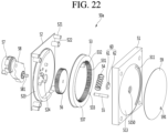
- FIG. 21 is a rear perspective view of a drawer provided with an elevation device according to another embodiment
- FIG. 22 is an exploded perspective view of an elevation device when viewed from a rear side according to another embodiment
- FIG. 23 is an exploded perspective view of the elevation device when viewed from a front side.
- an elevation device 50a may have a feature in which a structure for preventing foreign substances from being introduced into an elevation device through a guide slit 311, through which an elevation bar 55 passes, may be additionally provided at a rear surface of a sliding door 31 constituting a drawer 30.
- the elevation device 50a may have a feature in which a rotation plate 59 and a rotation plate holder 60 may be further added to the structure of the elevation device 50 according to the foregoing embodiment, and a rotation plate mounting hole may be disposed at a rear surface of the sliding door 31.
- the storage box itself constituting the drawer is not elevated, and a separate elevation plate may be provided in the storage box.
- a rail assembly for withdrawing the drawer may be connected to the side surface of the storage box.
Landscapes
- Engineering & Computer Science (AREA)
- Chemical & Material Sciences (AREA)
- Combustion & Propulsion (AREA)
- Physics & Mathematics (AREA)
- Mechanical Engineering (AREA)
- Thermal Sciences (AREA)
- General Engineering & Computer Science (AREA)
- Refrigerator Housings (AREA)
- Drawers Of Furniture (AREA)
Claims (14)
- Kühlschrank, der Folgendes umfasst:ein Gehäuse (10), das einen Vorratsraum (12) enthält; undeine Schublade (30), die gleitend in den Vorratsraum (12) hinein und aus diesem heraus bewegt werden kann,eine Hebeplatte (34), die in der Schublade (30) angeordnet ist; undeine Hebevorrichtung (50) zum Anheben der Hebeplatte (34),dadurch gekennzeichnet, dass die Hebevorrichtung (50) Folgendes umfasst:einen Antriebsmotor (57);eine gekrümmte Zahnstange (53), die so konfiguriert ist, dass sie durch den Antriebsmotor (57) gedreht wird; undeine Hebestange (55), die an einem Ende mit der gekrümmten Zahnstange (53) gekoppelt ist und am anderen Ende gegenüber dem einen Ende mit der Hebeplatte (34) beweglich in Eingriff ist, so dass die Hebestange (55) zusammen mit der gekrümmten Zahnstange (53) gedreht wird, um die Hebeplatte (34) anzuheben und abzusenken,wobei der Kühlschrank ferner eine Feder (54) umfasst, die längs eines Umfangs der gekrümmten Zahnstange (53) angeordnet ist und so konfiguriert ist, dass sie komprimiert wird, wenn die Hebeplatte (34) abgesenkt wird.
- Kühlschrank nach Anspruch 1, wobei die gekrümmte Zahnstange (53) jeweils eine kreisförmige Zahnstange oder eine bogenförmige Zahnstange umfasst, und/oder wobei die Drehachse der gekrümmten Zahnstange (55) entsprechend einem zentralen Abschnitt oder einer vertikalen Mittellinie der Hebeplatte (34) angeordnet ist und/oder wobei die Hebestange (55) mit der Hebeplatte (34) in Eingriff ist, so dass sie in einer horizontalen Richtung in Bezug auf die Hebeplatte (34) bewegt werden kann.
- Kühlschrank nach Anspruch 1 oder 2, der ferner ein Antriebszahnrad (56) umfasst, das über eine Zahnradverbindung mit der gekrümmten Zahnstange (53) verbunden ist, um die gekrümmte Zahnstange (53) zu drehen,wobei ein Zahnradteil (531) an einer Innenumfangsfläche oder einer Außenumfangsfläche der gekrümmten Zahnstange (53) angeordnet ist, unddas Antriebszahnrad (56) mit dem Zahnradteil (531) in Eingriff ist.
- Kühlschrank nach einem der vorhergehenden Ansprüche, der ferner ein Reduktionsgetriebe (58) umfasst, das mit einer Welle des Antriebsmotors (57) verbunden ist und konfiguriert ist, eine Drehzahl des Antriebsmotors (57) zu verringern,
wobei das Antriebszahnrad (57) mit einer Antriebswelle des Reduktionsgetriebes (58) verbunden ist. - Kühlschrank nach einem der vorhergehenden Ansprüche, wobei die Schublade eine Tür (31) und einen Vorratskasten (32), der an einer Innenfläche der Tür (31) vorgesehen ist, umfasst und wobei die Hebevorrichtung (50) an oder in der Tür (31) aufgenommen ist, und
die Hebestange (55) durch eine Fläche eines Gehäuses (51) und/oder eine Fläche der Tür (31) verläuft, um mit der Hebeplatte (34) in Eingriff zu gelangen. - Kühlschrank nach Anspruch 5, wobei ein bogenförmiger Führungsschlitz (311, 511) durch die Fläche gebildet ist, um eine Bewegung der Hebestange (34) zu führen.
- Kühlschrank nach einem der vorhergehenden Ansprüche, wobei die Hebestange (55) so mit der gekrümmten Zahnstange (53) gekoppelt ist, dass sie sich während einer Bewegung in einer horizontalen Richtung in Bezug auf die Hebeplatte (34) bogenförmig bewegt, um die Hebeplatte (34) anzuheben oder abzusenken.
- Kühlschrank nach einem der vorhergehenden Ansprüche, der ferner ein Leerlaufzahnrad (551) umfasst, das am anderen Ende der Hebestange (53) montiert ist, wobei die Hebeplatte (34) eine Führungszahnstange (342, 344) umfasst, mit der das Leerlaufzahnrad in Eingriff ist.
- Kühlschrank nach Anspruch 8, wobei die Hebeplatte (34) eine Führungsrille (343) oder eine Hebestangenführung (341) zum Führen einer Bewegung des Leerlaufzahnrads (551) umfasst.
- Kühlschrank nach Anspruch 1, der ferner eine Plattentragvorrichtung (60, 70) umfasst, die in der Schublade angeordnet ist und die Hebeplatte (34) trägt, um einen horizontalen Zustand aufrechtzuerhalten, während die Hebeplatte aus der Schublade (30) angehoben oder in die Schublade (30) abgesenkt wird.
- Kühlschrank nach Anspruch 10, wobei die Plattentragvorrichtung (60) ein Paar Scherengelenke (63) umfasst, die die Hebeplatte (34) mit der Schublade (30) koppeln, wobei die Scherengelenke (63) an gegenüberliegenden Seiten der Hebeplatte (34) angeordnet sind; und/oder
wobei die Plattentragvorrichtung (70) wenigstens eine Schienenanordnung umfasst, die die Hebeplatte (34) mit der Schublade (30) koppelt, wobei die Schienenanordnung eine feststehende Schiene (71), die mit der Schublade (30) verbunden ist, und eine bewegliche Schiene (72), die mit der Hebeplatte (34) verbunden ist und mit der feststehenden Schiene (71) beweglich verbunden ist, umfasst. - Kühlschrank nach Anspruch 1, der ferner eine zentrale Befestigung (513) umfasst, die angrenzend an eine Innenumfangsfläche der gekrümmten Zahnstange (53) angeordnet ist, wobei die zentrale Befestigung (513) einen Ansatz (515) aufweist, an dem ein Ende der Feder (54) anliegt; und
die gekrümmte Zahnstange (53) eine Federpressrippe (532) umfasst, die von der Innenumfangsfläche der gekrümmten Zahnstange (53) vorsteht, an der das andere Ende der Feder (54) anliegt. - Kühlschrank nach einem der vorhergehenden Ansprüche, der ferner ein Bedienungsteil (301) umfasst, das an der Schublade (30) vorgesehen ist und so konfiguriert ist, dass es mittels einer Berührung oder einer Taste bedient wird, um eine Eingabe eines Befehls zum Einsetzen bzw. Herausziehen der Schublade (30) und/oder einen Bedienungsbefehl für die Hebevorrichtung (34) zu erhalten.
- Kühlschrank nach einem der vorhergehenden Ansprüche, der ferner eine Bedienungsvorrichtung (302) umfasst, die an einem unteren Ende der untersten Schublade (30) vorgesehen ist,
wobei die Bedienungsvorrichtung (302) Folgendes umfasst:einen Sensor (302a) zum Detektieren einer Annäherung eines Benutzers undeine Bildprojektionsvorrichtung (302b), wobei die Bildprojektionsvorrichtung (302b) konfiguriert ist, ein Bild auf einen Boden eines Einbauraums zu projizieren, in dem der Kühlschrank eingebaut ist, wenn der Sensor die Annäherung eines Benutzers detektiert,wobei ein bestimmter Befehl, der den Befehl zum Hineinschieben bzw. Herausziehen der Schublade enthält, ausgeführt wird, wenn der Benutzer an das Bild herantritt, das auf den Boden projiziert wird.
Priority Applications (1)
| Application Number | Priority Date | Filing Date | Title |
|---|---|---|---|
| EP25152816.2A EP4542150A3 (de) | 2018-12-28 | 2019-12-18 | Kühlschrank |
Applications Claiming Priority (1)
| Application Number | Priority Date | Filing Date | Title |
|---|---|---|---|
| KR1020180172502A KR102583877B1 (ko) | 2018-12-28 | 2018-12-28 | 냉장고 |
Related Child Applications (1)
| Application Number | Title | Priority Date | Filing Date |
|---|---|---|---|
| EP25152816.2A Division EP4542150A3 (de) | 2018-12-28 | 2019-12-18 | Kühlschrank |
Publications (2)
| Publication Number | Publication Date |
|---|---|
| EP3674638A1 EP3674638A1 (de) | 2020-07-01 |
| EP3674638B1 true EP3674638B1 (de) | 2025-02-05 |
Family
ID=68965600
Family Applications (2)
| Application Number | Title | Priority Date | Filing Date |
|---|---|---|---|
| EP25152816.2A Pending EP4542150A3 (de) | 2018-12-28 | 2019-12-18 | Kühlschrank |
| EP19217526.3A Active EP3674638B1 (de) | 2018-12-28 | 2019-12-18 | Kühlschrank |
Family Applications Before (1)
| Application Number | Title | Priority Date | Filing Date |
|---|---|---|---|
| EP25152816.2A Pending EP4542150A3 (de) | 2018-12-28 | 2019-12-18 | Kühlschrank |
Country Status (6)
| Country | Link |
|---|---|
| US (1) | US10876787B2 (de) |
| EP (2) | EP4542150A3 (de) |
| KR (1) | KR102583877B1 (de) |
| CN (1) | CN111380300B (de) |
| AU (1) | AU2019283768B2 (de) |
| ES (1) | ES3012848T3 (de) |
Families Citing this family (4)
| Publication number | Priority date | Publication date | Assignee | Title |
|---|---|---|---|---|
| KR102595327B1 (ko) * | 2018-08-30 | 2023-10-30 | 엘지전자 주식회사 | 냉장고 |
| KR102579883B1 (ko) * | 2018-12-28 | 2023-09-18 | 엘지전자 주식회사 | 냉장고 |
| DE102021106164A1 (de) | 2021-02-25 | 2022-08-25 | Liebherr-Hausgeräte Lienz Gmbh | Kühl- und/oder Gefriergerät |
| CN113911012B (zh) * | 2021-11-10 | 2023-03-28 | 贵州电网有限责任公司 | 多功能移动式试验仪器操作台 |
Family Cites Families (27)
| Publication number | Priority date | Publication date | Assignee | Title |
|---|---|---|---|---|
| FR2614514B3 (fr) | 1987-04-29 | 1989-06-09 | Moulinex Sa | Support mobile destine a etre monte dans un meuble de cuisine pour permettre le rangement et/ou l'utilisation d'un appareil electromenager |
| US5115822A (en) | 1991-03-20 | 1992-05-26 | Nichols Will E | Dishwasher basket assembly including lift mechanism |
| JPH05296647A (ja) | 1992-04-14 | 1993-11-09 | Toshiba Corp | 冷蔵庫 |
| KR100263566B1 (ko) * | 1998-03-13 | 2000-08-01 | 윤종용 | 냉장고의 선반 승강장치 |
| KR100663410B1 (ko) * | 2001-08-31 | 2007-01-02 | 김회수 | 김치냉장고의 저장물 승강장치 및 그 제어방법 |
| CN1648581A (zh) * | 2004-01-29 | 2005-08-03 | 乐金电子(天津)电器有限公司 | 电冰箱的搁板设置结构 |
| KR100690645B1 (ko) | 2004-07-15 | 2007-03-09 | 엘지전자 주식회사 | 바스켓 승강장치를 구비한 냉장고 |
| KR100690647B1 (ko) * | 2004-07-29 | 2007-03-09 | 엘지전자 주식회사 | 바스켓 승강장치를 구비한 냉장고 |
| KR100652583B1 (ko) * | 2004-07-29 | 2006-12-06 | 엘지전자 주식회사 | 바스켓 승강장치를 구비한 냉장고 |
| KR100619732B1 (ko) * | 2004-07-29 | 2006-09-08 | 엘지전자 주식회사 | 바스켓 승강장치를 구비한 냉장고 |
| KR20060025806A (ko) * | 2004-09-17 | 2006-03-22 | 엘지전자 주식회사 | 냉장고 |
| KR100564412B1 (ko) | 2004-11-19 | 2006-03-28 | 주식회사 대우일렉트로닉스 | 냉장고의 서랍 승강장치 |
| KR20080101334A (ko) * | 2007-05-17 | 2008-11-21 | 삼성전자주식회사 | 냉장고 |
| KR100930352B1 (ko) * | 2008-01-31 | 2009-12-08 | 조동현 | 열전소자를 이용한 소형냉장고가 승강식으로 구비된 테이블 |
| US8220887B2 (en) | 2009-02-27 | 2012-07-17 | Electrolux Home Products, Inc. | Selectable presentation of dual-bin system |
| CN201497287U (zh) * | 2009-07-15 | 2010-06-02 | 苏州三星电子有限公司 | 升降式冰箱搁架 |
| TR201113318A1 (tr) | 2011-12-30 | 2013-08-22 | Arcelik As | Yüksekliği değiştirilebilen bir raf içeren bir soğutucu. |
| US9377238B2 (en) | 2013-03-14 | 2016-06-28 | Electrolux Home Products, Inc. | Refrigerator with a scissor-type lift mechanism |
| CN104344676B (zh) * | 2014-03-03 | 2017-01-18 | 海尔集团公司 | 储物盒组件和具有该储物盒组件的冰箱 |
| KR101720490B1 (ko) * | 2014-12-31 | 2017-03-28 | 엘지전자 주식회사 | 냉장고 |
| CN204963403U (zh) * | 2015-07-30 | 2016-01-13 | 合肥美的电冰箱有限公司 | 酒架及冰箱 |
| WO2018088802A1 (en) * | 2016-11-10 | 2018-05-17 | Samsung Electronics Co., Ltd. | Lifting device and refrigerator including the same |
| JP2018200160A (ja) | 2016-11-10 | 2018-12-20 | 三星電子株式会社Samsung Electronics Co.,Ltd. | 昇降機構、昇降ユニットを備える冷蔵庫及び洗濯機 |
| DE102017207220A1 (de) | 2017-04-28 | 2018-10-31 | BSH Hausgeräte GmbH | Darstellung von Information an einem Kühlgerät |
| CN107062761B (zh) | 2017-06-15 | 2019-08-27 | 合肥华凌股份有限公司 | 风道出风控制结构及风冷冰箱 |
| CN108759281B (zh) | 2018-04-10 | 2021-04-23 | 海尔智家股份有限公司 | 升降支撑装置及具有其的冰箱 |
| KR102474912B1 (ko) * | 2018-06-11 | 2022-12-06 | 엘지전자 주식회사 | 냉장고 |
-
2018
- 2018-12-28 KR KR1020180172502A patent/KR102583877B1/ko active Active
-
2019
- 2019-11-07 US US16/677,335 patent/US10876787B2/en active Active
- 2019-12-16 AU AU2019283768A patent/AU2019283768B2/en active Active
- 2019-12-18 EP EP25152816.2A patent/EP4542150A3/de active Pending
- 2019-12-18 ES ES19217526T patent/ES3012848T3/es active Active
- 2019-12-18 EP EP19217526.3A patent/EP3674638B1/de active Active
- 2019-12-23 CN CN201911337463.6A patent/CN111380300B/zh active Active
Also Published As
| Publication number | Publication date |
|---|---|
| US20200208906A1 (en) | 2020-07-02 |
| CN111380300B (zh) | 2022-01-21 |
| AU2019283768B2 (en) | 2020-10-15 |
| EP3674638A1 (de) | 2020-07-01 |
| KR20200082175A (ko) | 2020-07-08 |
| ES3012848T3 (en) | 2025-04-10 |
| AU2019283768A1 (en) | 2020-07-16 |
| US10876787B2 (en) | 2020-12-29 |
| CN111380300A (zh) | 2020-07-07 |
| EP4542150A2 (de) | 2025-04-23 |
| KR102583877B1 (ko) | 2023-10-04 |
| EP4542150A3 (de) | 2025-06-25 |
Similar Documents
| Publication | Publication Date | Title |
|---|---|---|
| US10939758B2 (en) | Refrigerator | |
| EP3546862B1 (de) | Kühlschrank | |
| EP3581865B1 (de) | Kühlschrank | |
| EP3674638B1 (de) | Kühlschrank | |
| EP3617630B1 (de) | Kühlschrank | |
| US11656024B2 (en) | Refrigerator | |
| EP4530561B1 (de) | Kühlschrank | |
| US10900708B2 (en) | Refrigerator | |
| KR20260000237A (ko) | 냉장고 |
Legal Events
| Date | Code | Title | Description |
|---|---|---|---|
| PUAI | Public reference made under article 153(3) epc to a published international application that has entered the european phase |
Free format text: ORIGINAL CODE: 0009012 |
|
| STAA | Information on the status of an ep patent application or granted ep patent |
Free format text: STATUS: REQUEST FOR EXAMINATION WAS MADE |
|
| 17P | Request for examination filed |
Effective date: 20191218 |
|
| AK | Designated contracting states |
Kind code of ref document: A1 Designated state(s): AL AT BE BG CH CY CZ DE DK EE ES FI FR GB GR HR HU IE IS IT LI LT LU LV MC MK MT NL NO PL PT RO RS SE SI SK SM TR |
|
| AX | Request for extension of the european patent |
Extension state: BA ME |
|
| RBV | Designated contracting states (corrected) |
Designated state(s): AL AT BE BG CH CY CZ DE DK EE ES FI FR GB GR HR HU IE IS IT LI LT LU LV MC MK MT NL NO PL PT RO RS SE SI SK SM TR |
|
| STAA | Information on the status of an ep patent application or granted ep patent |
Free format text: STATUS: EXAMINATION IS IN PROGRESS |
|
| 17Q | First examination report despatched |
Effective date: 20221215 |
|
| RIC1 | Information provided on ipc code assigned before grant |
Ipc: A47B 88/90 20170101ALN20240716BHEP Ipc: F25D 23/02 20060101ALI20240716BHEP Ipc: F25D 25/04 20060101ALI20240716BHEP Ipc: F25D 25/02 20060101AFI20240716BHEP |
|
| GRAP | Despatch of communication of intention to grant a patent |
Free format text: ORIGINAL CODE: EPIDOSNIGR1 |
|
| STAA | Information on the status of an ep patent application or granted ep patent |
Free format text: STATUS: GRANT OF PATENT IS INTENDED |
|
| INTG | Intention to grant announced |
Effective date: 20240829 |
|
| GRAS | Grant fee paid |
Free format text: ORIGINAL CODE: EPIDOSNIGR3 |
|
| GRAA | (expected) grant |
Free format text: ORIGINAL CODE: 0009210 |
|
| STAA | Information on the status of an ep patent application or granted ep patent |
Free format text: STATUS: THE PATENT HAS BEEN GRANTED |
|
| AK | Designated contracting states |
Kind code of ref document: B1 Designated state(s): AL AT BE BG CH CY CZ DE DK EE ES FI FR GB GR HR HU IE IS IT LI LT LU LV MC MK MT NL NO PL PT RO RS SE SI SK SM TR |
|
| REG | Reference to a national code |
Ref country code: GB Ref legal event code: FG4D |
|
| REG | Reference to a national code |
Ref country code: CH Ref legal event code: EP |
|
| REG | Reference to a national code |
Ref country code: IE Ref legal event code: FG4D |
|
| REG | Reference to a national code |
Ref country code: DE Ref legal event code: R096 Ref document number: 602019065616 Country of ref document: DE |
|
| REG | Reference to a national code |
Ref country code: ES Ref legal event code: FG2A Ref document number: 3012848 Country of ref document: ES Kind code of ref document: T3 Effective date: 20250410 |
|
| REG | Reference to a national code |
Ref country code: NL Ref legal event code: MP Effective date: 20250205 |
|
| RAP4 | Party data changed (patent owner data changed or rights of a patent transferred) |
Owner name: LG ELECTRONICS INC. |
|
| PG25 | Lapsed in a contracting state [announced via postgrant information from national office to epo] |
Ref country code: RS Free format text: LAPSE BECAUSE OF FAILURE TO SUBMIT A TRANSLATION OF THE DESCRIPTION OR TO PAY THE FEE WITHIN THE PRESCRIBED TIME-LIMIT Effective date: 20250505 |
|
| PG25 | Lapsed in a contracting state [announced via postgrant information from national office to epo] |
Ref country code: FI Free format text: LAPSE BECAUSE OF FAILURE TO SUBMIT A TRANSLATION OF THE DESCRIPTION OR TO PAY THE FEE WITHIN THE PRESCRIBED TIME-LIMIT Effective date: 20250205 |
|
| PG25 | Lapsed in a contracting state [announced via postgrant information from national office to epo] |
Ref country code: PL Free format text: LAPSE BECAUSE OF FAILURE TO SUBMIT A TRANSLATION OF THE DESCRIPTION OR TO PAY THE FEE WITHIN THE PRESCRIBED TIME-LIMIT Effective date: 20250205 |
|
| REG | Reference to a national code |
Ref country code: LT Ref legal event code: MG9D |
|
| PG25 | Lapsed in a contracting state [announced via postgrant information from national office to epo] |
Ref country code: NO Free format text: LAPSE BECAUSE OF FAILURE TO SUBMIT A TRANSLATION OF THE DESCRIPTION OR TO PAY THE FEE WITHIN THE PRESCRIBED TIME-LIMIT Effective date: 20250505 Ref country code: IS Free format text: LAPSE BECAUSE OF FAILURE TO SUBMIT A TRANSLATION OF THE DESCRIPTION OR TO PAY THE FEE WITHIN THE PRESCRIBED TIME-LIMIT Effective date: 20250605 |
|
| PG25 | Lapsed in a contracting state [announced via postgrant information from national office to epo] |
Ref country code: NL Free format text: LAPSE BECAUSE OF FAILURE TO SUBMIT A TRANSLATION OF THE DESCRIPTION OR TO PAY THE FEE WITHIN THE PRESCRIBED TIME-LIMIT Effective date: 20250205 |
|
| PG25 | Lapsed in a contracting state [announced via postgrant information from national office to epo] |
Ref country code: HR Free format text: LAPSE BECAUSE OF FAILURE TO SUBMIT A TRANSLATION OF THE DESCRIPTION OR TO PAY THE FEE WITHIN THE PRESCRIBED TIME-LIMIT Effective date: 20250205 |
|
| PG25 | Lapsed in a contracting state [announced via postgrant information from national office to epo] |
Ref country code: LV Free format text: LAPSE BECAUSE OF FAILURE TO SUBMIT A TRANSLATION OF THE DESCRIPTION OR TO PAY THE FEE WITHIN THE PRESCRIBED TIME-LIMIT Effective date: 20250205 Ref country code: PT Free format text: LAPSE BECAUSE OF FAILURE TO SUBMIT A TRANSLATION OF THE DESCRIPTION OR TO PAY THE FEE WITHIN THE PRESCRIBED TIME-LIMIT Effective date: 20250605 |
|
| PG25 | Lapsed in a contracting state [announced via postgrant information from national office to epo] |
Ref country code: BG Free format text: LAPSE BECAUSE OF FAILURE TO SUBMIT A TRANSLATION OF THE DESCRIPTION OR TO PAY THE FEE WITHIN THE PRESCRIBED TIME-LIMIT Effective date: 20250205 |
|
| REG | Reference to a national code |
Ref country code: AT Ref legal event code: MK05 Ref document number: 1764950 Country of ref document: AT Kind code of ref document: T Effective date: 20250205 |
|
| PG25 | Lapsed in a contracting state [announced via postgrant information from national office to epo] |
Ref country code: SE Free format text: LAPSE BECAUSE OF FAILURE TO SUBMIT A TRANSLATION OF THE DESCRIPTION OR TO PAY THE FEE WITHIN THE PRESCRIBED TIME-LIMIT Effective date: 20250205 |
|
| PG25 | Lapsed in a contracting state [announced via postgrant information from national office to epo] |
Ref country code: SM Free format text: LAPSE BECAUSE OF FAILURE TO SUBMIT A TRANSLATION OF THE DESCRIPTION OR TO PAY THE FEE WITHIN THE PRESCRIBED TIME-LIMIT Effective date: 20250205 |
|
| PG25 | Lapsed in a contracting state [announced via postgrant information from national office to epo] |
Ref country code: DK Free format text: LAPSE BECAUSE OF FAILURE TO SUBMIT A TRANSLATION OF THE DESCRIPTION OR TO PAY THE FEE WITHIN THE PRESCRIBED TIME-LIMIT Effective date: 20250205 |
|
| PG25 | Lapsed in a contracting state [announced via postgrant information from national office to epo] |
Ref country code: AT Free format text: LAPSE BECAUSE OF FAILURE TO SUBMIT A TRANSLATION OF THE DESCRIPTION OR TO PAY THE FEE WITHIN THE PRESCRIBED TIME-LIMIT Effective date: 20250205 |
|
| PG25 | Lapsed in a contracting state [announced via postgrant information from national office to epo] |
Ref country code: CZ Free format text: LAPSE BECAUSE OF FAILURE TO SUBMIT A TRANSLATION OF THE DESCRIPTION OR TO PAY THE FEE WITHIN THE PRESCRIBED TIME-LIMIT Effective date: 20250205 Ref country code: EE Free format text: LAPSE BECAUSE OF FAILURE TO SUBMIT A TRANSLATION OF THE DESCRIPTION OR TO PAY THE FEE WITHIN THE PRESCRIBED TIME-LIMIT Effective date: 20250205 |
|
| PG25 | Lapsed in a contracting state [announced via postgrant information from national office to epo] |
Ref country code: RO Free format text: LAPSE BECAUSE OF FAILURE TO SUBMIT A TRANSLATION OF THE DESCRIPTION OR TO PAY THE FEE WITHIN THE PRESCRIBED TIME-LIMIT Effective date: 20250205 |
|
| PG25 | Lapsed in a contracting state [announced via postgrant information from national office to epo] |
Ref country code: SK Free format text: LAPSE BECAUSE OF FAILURE TO SUBMIT A TRANSLATION OF THE DESCRIPTION OR TO PAY THE FEE WITHIN THE PRESCRIBED TIME-LIMIT Effective date: 20250205 |
|
| REG | Reference to a national code |
Ref country code: DE Ref legal event code: R097 Ref document number: 602019065616 Country of ref document: DE |
|
| PLBE | No opposition filed within time limit |
Free format text: ORIGINAL CODE: 0009261 |
|
| STAA | Information on the status of an ep patent application or granted ep patent |
Free format text: STATUS: NO OPPOSITION FILED WITHIN TIME LIMIT |
|
| PGFP | Annual fee paid to national office [announced via postgrant information from national office to epo] |
Ref country code: DE Payment date: 20251105 Year of fee payment: 7 |
|
| PGFP | Annual fee paid to national office [announced via postgrant information from national office to epo] |
Ref country code: GB Payment date: 20251105 Year of fee payment: 7 |
|
| 26N | No opposition filed |
Effective date: 20251106 |
|
| PGFP | Annual fee paid to national office [announced via postgrant information from national office to epo] |
Ref country code: IT Payment date: 20251106 Year of fee payment: 7 |
|
| PGFP | Annual fee paid to national office [announced via postgrant information from national office to epo] |
Ref country code: FR Payment date: 20251111 Year of fee payment: 7 |
|
| PGFP | Annual fee paid to national office [announced via postgrant information from national office to epo] |
Ref country code: ES Payment date: 20260122 Year of fee payment: 7 |