EP3674663A1 - Dispositif de guidage de trajet de déplacement - Google Patents
Dispositif de guidage de trajet de déplacement Download PDFInfo
- Publication number
- EP3674663A1 EP3674663A1 EP18871466.1A EP18871466A EP3674663A1 EP 3674663 A1 EP3674663 A1 EP 3674663A1 EP 18871466 A EP18871466 A EP 18871466A EP 3674663 A1 EP3674663 A1 EP 3674663A1
- Authority
- EP
- European Patent Office
- Prior art keywords
- traveling route
- preparation
- construction machine
- gradient
- route
- Prior art date
- Legal status (The legal status is an assumption and is not a legal conclusion. Google has not performed a legal analysis and makes no representation as to the accuracy of the status listed.)
- Granted
Links
Images



Classifications
-
- G—PHYSICS
- G01—MEASURING; TESTING
- G01C—MEASURING DISTANCES, LEVELS OR BEARINGS; SURVEYING; NAVIGATION; GYROSCOPIC INSTRUMENTS; PHOTOGRAMMETRY OR VIDEOGRAMMETRY
- G01C21/00—Navigation; Navigational instruments not provided for in groups G01C1/00 - G01C19/00
- G01C21/26—Navigation; Navigational instruments not provided for in groups G01C1/00 - G01C19/00 specially adapted for navigation in a road network
- G01C21/34—Route searching; Route guidance
-
- G—PHYSICS
- G01—MEASURING; TESTING
- G01C—MEASURING DISTANCES, LEVELS OR BEARINGS; SURVEYING; NAVIGATION; GYROSCOPIC INSTRUMENTS; PHOTOGRAMMETRY OR VIDEOGRAMMETRY
- G01C21/00—Navigation; Navigational instruments not provided for in groups G01C1/00 - G01C19/00
- G01C21/20—Instruments for performing navigational calculations
-
- E—FIXED CONSTRUCTIONS
- E02—HYDRAULIC ENGINEERING; FOUNDATIONS; SOIL SHIFTING
- E02F—DREDGING; SOIL-SHIFTING
- E02F9/00—Component parts of dredgers or soil-shifting machines, not restricted to one of the kinds covered by groups E02F3/00 - E02F7/00
- E02F9/20—Drives; Control devices
- E02F9/2025—Particular purposes of control systems not otherwise provided for
- E02F9/2045—Guiding machines along a predetermined path
-
- E—FIXED CONSTRUCTIONS
- E02—HYDRAULIC ENGINEERING; FOUNDATIONS; SOIL SHIFTING
- E02F—DREDGING; SOIL-SHIFTING
- E02F9/00—Component parts of dredgers or soil-shifting machines, not restricted to one of the kinds covered by groups E02F3/00 - E02F7/00
- E02F9/20—Drives; Control devices
- E02F9/2025—Particular purposes of control systems not otherwise provided for
- E02F9/205—Remotely operated machines, e.g. unmanned vehicles
-
- G—PHYSICS
- G01—MEASURING; TESTING
- G01C—MEASURING DISTANCES, LEVELS OR BEARINGS; SURVEYING; NAVIGATION; GYROSCOPIC INSTRUMENTS; PHOTOGRAMMETRY OR VIDEOGRAMMETRY
- G01C21/00—Navigation; Navigational instruments not provided for in groups G01C1/00 - G01C19/00
- G01C21/005—Navigation; Navigational instruments not provided for in groups G01C1/00 - G01C19/00 with correlation of navigation data from several sources, e.g. map or contour matching
-
- G—PHYSICS
- G01—MEASURING; TESTING
- G01C—MEASURING DISTANCES, LEVELS OR BEARINGS; SURVEYING; NAVIGATION; GYROSCOPIC INSTRUMENTS; PHOTOGRAMMETRY OR VIDEOGRAMMETRY
- G01C21/00—Navigation; Navigational instruments not provided for in groups G01C1/00 - G01C19/00
- G01C21/04—Navigation; Navigational instruments not provided for in groups G01C1/00 - G01C19/00 by terrestrial means
-
- G—PHYSICS
- G01—MEASURING; TESTING
- G01C—MEASURING DISTANCES, LEVELS OR BEARINGS; SURVEYING; NAVIGATION; GYROSCOPIC INSTRUMENTS; PHOTOGRAMMETRY OR VIDEOGRAMMETRY
- G01C21/00—Navigation; Navigational instruments not provided for in groups G01C1/00 - G01C19/00
- G01C21/26—Navigation; Navigational instruments not provided for in groups G01C1/00 - G01C19/00 specially adapted for navigation in a road network
- G01C21/34—Route searching; Route guidance
- G01C21/3453—Special cost functions, i.e. other than distance or default speed limit of road segments
- G01C21/3469—Fuel consumption; Energy use; Emission aspects
-
- G—PHYSICS
- G05—CONTROLLING; REGULATING
- G05D—SYSTEMS FOR CONTROLLING OR REGULATING NON-ELECTRIC VARIABLES
- G05D1/00—Control of position, course, altitude or attitude of land, water, air or space vehicles, e.g. using automatic pilots
- G05D1/02—Control of position or course in two dimensions
- G05D1/021—Control of position or course in two dimensions specially adapted to land vehicles
- G05D1/0212—Control of position or course in two dimensions specially adapted to land vehicles with means for defining a desired trajectory
- G05D1/0214—Control of position or course in two dimensions specially adapted to land vehicles with means for defining a desired trajectory in accordance with safety or protection criteria, e.g. avoiding hazardous areas
-
- G—PHYSICS
- G05—CONTROLLING; REGULATING
- G05D—SYSTEMS FOR CONTROLLING OR REGULATING NON-ELECTRIC VARIABLES
- G05D1/00—Control of position, course, altitude or attitude of land, water, air or space vehicles, e.g. using automatic pilots
- G05D1/02—Control of position or course in two dimensions
- G05D1/021—Control of position or course in two dimensions specially adapted to land vehicles
- G05D1/0212—Control of position or course in two dimensions specially adapted to land vehicles with means for defining a desired trajectory
- G05D1/0217—Control of position or course in two dimensions specially adapted to land vehicles with means for defining a desired trajectory in accordance with energy consumption, time reduction or distance reduction criteria
-
- G—PHYSICS
- G05—CONTROLLING; REGULATING
- G05D—SYSTEMS FOR CONTROLLING OR REGULATING NON-ELECTRIC VARIABLES
- G05D1/00—Control of position, course, altitude or attitude of land, water, air or space vehicles, e.g. using automatic pilots
- G05D1/02—Control of position or course in two dimensions
- G05D1/021—Control of position or course in two dimensions specially adapted to land vehicles
- G05D1/0268—Control of position or course in two dimensions specially adapted to land vehicles using internal positioning means
- G05D1/0274—Control of position or course in two dimensions specially adapted to land vehicles using internal positioning means using mapping information stored in a memory device
-
- G—PHYSICS
- G08—SIGNALLING
- G08G—TRAFFIC CONTROL SYSTEMS
- G08G1/00—Traffic control systems for road vehicles
- G08G1/09—Arrangements for giving variable traffic instructions
- G08G1/0962—Arrangements for giving variable traffic instructions having an indicator mounted inside the vehicle, e.g. giving voice messages
- G08G1/0968—Systems involving transmission of navigation instructions to the vehicle
- G08G1/0969—Systems involving transmission of navigation instructions to the vehicle having a display in the form of a map
-
- G—PHYSICS
- G09—EDUCATION; CRYPTOGRAPHY; DISPLAY; ADVERTISING; SEALS
- G09B—EDUCATIONAL OR DEMONSTRATION APPLIANCES; APPLIANCES FOR TEACHING, OR COMMUNICATING WITH, THE BLIND, DEAF OR MUTE; MODELS; PLANETARIA; GLOBES; MAPS; DIAGRAMS
- G09B29/00—Maps; Plans; Charts; Diagrams, e.g. route diagram
-
- G—PHYSICS
- G09—EDUCATION; CRYPTOGRAPHY; DISPLAY; ADVERTISING; SEALS
- G09B—EDUCATIONAL OR DEMONSTRATION APPLIANCES; APPLIANCES FOR TEACHING, OR COMMUNICATING WITH, THE BLIND, DEAF OR MUTE; MODELS; PLANETARIA; GLOBES; MAPS; DIAGRAMS
- G09B29/00—Maps; Plans; Charts; Diagrams, e.g. route diagram
- G09B29/10—Map spot or coordinate position indicators; Map reading aids
Definitions
- the present invention relates to a traveling route guidance device which performs a guide of a traveling route for a construction machine.
- Patent Literature 1 discloses the below-described technology of preventing a vehicle from failing to climb a slope having a steep gradient when an electrically driven motor can output only a decreased torque due to a breakage or abnormality occurring in a motor controller during driving of the electrically driven motor in a weak magnetic field state.
- Patent Literature 1 discloses deriving from map data a specific route from a current position of the vehicle to a destination, the route excluding any slope having a predetermined gradient ratio or higher (claim 5).
- the aforementioned technology has a problem that no traveling route is derived in a case that the vehicle cannot reach the destination without passing through a route including a slope having such a predetermined gradient ratio or higher.
- Patent Literature 1 Japanese Unexamined Patent Publication No. 2009-268270
- the present invention has an object to provide a traveling route guidance device which can perform a guide for enabling a construction machine to easily reach a destination even in a case of having to travel in an impermissible range of a gradient.
- a traveling route guidance device includes: a landform acquiring part which acquires three-dimensional landform information about a landform around a construction machine; a current position acquiring part which acquires a current position of the construction machine with respect to the three-dimensional landform information; a destination acquiring part which acquires a destination with respect to the three-dimensional landform information; a controller which derives at least one traveling route from the current position to the destination for the construction machine based on the three-dimensional landform information; an output part which outputs information about a traveling route derived by the controller; and a memory which stores permissible range information representing a permissible range of a gradient determined in terms of a stability of the construction machine in advance, wherein when deriving a preparation-unrequired route which is a traveling route which enables the construction machine to travel thereon only within the permissible range of the gradient until reaching the destination, the controller causes the output part to output information about the preparation-unrequired route, and when not deriving the preparation-
- This configuration makes it possible to perform a guide for enabling a construction machine to easily reach a destination even in the case of having to travel in an impermissible range of a gradient.
- a construction machine 10 and a traveling route guidance device 20 will be described with reference to Figs. 1 to 6 .
- the construction machine 10 is a machine, e.g., an excavator, which performs an operation of a construction work or the like and is adapted for a preparation of a landform.
- the construction machine 10 may be operated in an operating room thereof, externally and remotely operated, or automatically controlled. Each operational way is applicable to other operations as well as the traveling operation.
- the construction machine 10 includes a lower traveling body 11, an upper slewing body 13, and an attachment 15.
- the lower traveling body 11 has right and left crawlers 11c for enabling the construction machine 10 to travel forward and backward.
- the upper slewing body 13 is slewable in the direction of yawing with respect to the lower traveling body 11 owing to a driving force from an electrically driven motor or a hydraulic motor.
- the attachment 15 includes a boom rotatably attached to the upper slewing body 13, an arm swingably attached to the boom, and a bucket rotatably attached to the arm, and performs the preparation of the landform.
- Each of the arm, the boom, and the bucket is swung or rotated by an actuator such as a hydraulic cylinder.
- the attachment 15 has a configuration in which the bucket is replaceable with other working component such as a breaker or a nibbler.
- the traveling route guidance device 20 performs a guide (support and assistance) of a traveling route R for the construction machine 10 in consideration of a slope in a landform around the construction machine 10.
- the traveling route guidance device 20 may be provided on the construction machine 10, an outside of the construction machine 10, or both the construction machine 10 and the outside thereof.
- the traveling route guidance device 20 is provided on the outside of the construction machine 10
- the traveling route guidance device 20 is, for example, mounted to a server communicatively connected with the construction machine 10.
- a part of the structural components of the traveling route guidance device 20 is, for example, mounted to the construction machine 10, and the remaining structural components are mounted to the server.
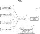
- the traveling route guidance device 20 includes a landform acquiring part 21, a current position acquiring part 22, a selecting part 31, a controller 40, an output part 50, and a memory 60.
- the landform acquiring part 21 acquires three-dimensional landform information T about the landform around the construction machine 10.
- the three-dimensional landform information T includes positional data respectively representing a plurality of positions in a three-dimensional coordinate space defined by an X-axis extending in a horizontal direction, a Y-axis extending in a vertical direction, and a Z-axis extending in a height direction perpendicularly intersecting the X and Y-axes.
- a positional datum consists of three components X, Y, and Z.
- the component X indicates a latitude
- the component Y indicates a longitude
- the component Z indicates an elevation.
- a degree of a gradient in a certain direction at each of the positions of the three-dimensional landform information T enables to be computed using the positional data included in the three-dimensional land form information T.
- the landform acquiring part 21 is made up of, for example, a distance image sensor mounted on the construction machine 10.
- the distance image sensor may measure a three-dimensional form by a TOF (Time-of-Flight) way or a stereo camera.
- the landform acquiring part 21 may obtain the three-dimensional landform information by taking an image from the sky.
- the landform acquiring part 21 can be mounted to a flying object, e.g., a drone, which is communicative with the construction machine 10.
- the memory 60 may store the three-dimensional landform information T in advance. This configuration allows the landform acquiring part 21 to acquire the three-dimensional landform information T from the memory 60.
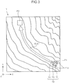
- the landform of the three-dimensional landform information T is represented by contours.
- the current position acquiring part 22 acquires a current position P1 of the construction machine 10 with respect to the three-dimensional landform information T.
- the current position acquiring part 22 is made up of, for instance, a GPS sensor which acquires the current position P1 by using a satellite positioning system.
- the sensor is a mere example.
- the current position acquiring part 22 may acquire the current position P1 by taking an image from the sky.
- the current position acquiring part 22 is made up of a distance image sensor and a GPS sensor mounted on the flying object.
- the current position acquiring part 22 calculates a relative position of the construction machine 10 to the flying object from a measured value of the distance image sensor, and calculates the position of the construction machine 10 by using a self-position and the relative position obtained from the GPS sensor.
- the current position acquiring part 22 may be made up of an input device, e.g., a switch, a touch panel, and a keyboard, and acquires the current position P1 in response to an operation of a user of the traveling route guidance device 20 (hereinafter, simply referred to as a "user").
- a user e.g., a user of the traveling route guidance device 20
- the current position acquiring part 22 acquires the current position P1 by permitting the user to input the coordinate of the current position P1.
- the current position acquiring part 22 may acquire the current position P1 by permitting the user to designate a position on a map displayed on a display device.
- the destination acquiring part 23 acquires a destination P2 of the construction machine 10 with respect to the three-dimensional landform information T.
- the destination acquiring part 23 is made up of an input device, e.g., a switch, a touch panel, and a keyboard, and acquires the destination P2 in response to an operation of the user. It is sufficient in this case that the destination acquiring part 23 acquires the destination P2 by permitting the user to input the coordinate of the destination P2. Moreover, in this case, the destination acquiring part 23 acquires the current position P1 by permitting the user to designate a position on a map displayed on a display device. Further, the destination acquiring part 23 may acquire the destination P2 from the memory which stores the destination P2 in advance. In the case that the construction machine 10 is remotely operated or automatically controlled, the destination acquiring part 23 may acquire the destination P2 by using a communication device to receive the destination externally transmitted via a transmission channel.
- the selecting part 31 (see Fig. 1 ) is made up of, for example, an input device and a display device, and permits the user to select a specific traveling route R from a plurality of candidate traveling routes R shown in Fig. 6 .
- the selecting part 31 may permit the user to use an input device, e.g., a switch, thereby selecting the specific traveling route R from the plurality of candidate traveling routes R displayed on the display device.
- the controller 40 is made up of a computer including a processor, such as a CPU, and a ROM, and performs calculations including: an input and an output of information; storing of the information; and deriving of a traveling route R.
- a processor such as a CPU
- ROM read-only memory
- the deriving of the traveling route R will be described in detail later.
- the output part 50 is made up of, for example, a display device and a speaker, and outputs information about the traveling route R.
- the information about the traveling route R includes an image and a voice adoptable for guiding the construction machine 10 on the traveling route R from the current position P1 to the destination P2.
- the memory 60 is, for example, a non-volatile memory, and stores a permissible range table 61.
- the operation executed by the traveling route guidance device 20 shown in Fig. 1 will be described with reference to the flowchart shown in Fig. 2 .
- the aforementioned structural components of the traveling route guidance device 20 will be described with mainly reference to Fig. 1 , and respective steps in the flowchart will be described with reference to Fig. 2 .
- the landform acquiring part 21 acquires the three-dimensional landform information T about the landform around the construction machine 10 shown in Fig. 3 (Step S11), and inputs the acquired information in the controller 40.
- the current position acquiring part 22 acquires the current position P1 of the construction machine 10 (Step S12), and inputs the acquired current position in the controller 40.
- the destination acquiring part 23 acquires the destination P2 (Step S13), and inputs the acquired destination in the controller 40.
- the controller 40 derives a traveling route R from the current position P1 to the destination P2 for the construction machine 10 based on the three-dimensional landform information T (Step S21).
- the controller 40 may derive, for instance, one or more traveling routes R by executing the processings described below.
- the controller 40 divides the three-dimensional landform information T into a plurality of blocks by partitioning the three-dimensional landform information T into grids on an X-Y plane.
- Each of the blocks may be in a square or rectangular shape having a predetermined size.
- the controller 40 defines respective centers of the blocks as nodes, and sets a graph in which the centers are linearly linked with each other.
- the distance between the linked centers is exemplified by a distance between the nodes.
- the controller 40 derives one or more traveling routes R from the current position P1 to the destination P2 by applying various route deriving algorisms to the three-dimensional landform information T.
- the route deriving algorisms include depth-priority deriving, width-priority deriving, uniform-cost deriving, A-star algorithm, Dijkstra's algorithm, and random deriving. In this manner, a plurality of traveling routes R are obtainable.
- the controller 40 detects from the traveling routes R derived in Step S21 a preparation-unrequired route R1 which achieves traveling from the current position P1 only within a permissible range of a gradient until reaching the destination P2.
- the controller 40 detects a preparation-unrequired route R1 by comparing a degree of a gradient with a predetermined permissible range.
- the degree of the gradient can be defined by, for example, a gradient ratio or an angle with respect to a horizontal plane.
- the permissible range of the gradient is determined in terms of the stability of the construction machine 10. Such a gentle gradient as to permit the construction machine 10 to stably travel is determined to fall within the permissible range. Conversely, such a steep gradient as to hinder the construction machine 10 from traveling is determined to deviate from the permissible range.
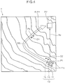
- Fig. 4 shows a gradient direction D1 that indicates a direction in which the degree of the gradient reaches maximum , that is, a height direction in which an amount of change reaches the maximum.
- Fig. 4 exemplifies the gradient direction D1 at a specific location Px.
- an advancing direction D2 of the crawler 11c indicating a direction in which the right and left crawlers 11c extend, that is, a direction (i.e., front-rear direction) in which the lower traveling body 11 advances.
- the stability of the construction machine 10 depends on the advancing direction D2 of the crawler 11c with respect to the gradient direction D1. Specifically, the stability of the construction machine 10 increases as the angle between the gradient direction D1 and the advancing direction D2 of the crawler 11c decreases even at the same degree of the gradient.
- the landform shown in Fig. 4 includes a traveling route Rx linearly running from the current position P1 to the destination P2.
- the traveling route Rx is highly likely to hinder the construction machine 10 from reaching the destination P2 in a stable state. This is because the traveling route Rx involves a large angle between the gradient direction D1 and the advancing direction D2 of the crawler 11c, and consequently, the degree of the gradient is highly likely to exceed the permissible range at a specific location.
- a traveling route like a traveling route R5, passing through a relay location P5 to reach a destination P2 and causing the construction machine 10 to travel a slope in an ascending or descending direction of the slope involves an angle of approximately 0° between the gradient direction D1 and the advancing direction D2 of the crawler 11c at the location where the gradient direction D1 and the advancing direction D2 of the crawler 11c are substantially the same. Therefore, the traveling route R5 has an increased possibility that the degree of the gradient at the location falls within the permissible range, and consequently permits the construction machine 10 to reach the destination P2 in a stable state.
- the permissible range of the gradient is set depending on the advancing direction D2 of the crawler 11c with respect to the gradient direction D1. For instance, the permissible range of the gradient is set at the maximum for the angle of 0° between the gradient direction D1 and the advancing direction D2 of the crawler 11c. This setting can increase the possibility that even a location having a steep degree of a gradient is determined to fall within the permissible range of the gradient under the condition that the angle between the gradient direction D1 and the advancing direction D2 of crawler 11c is 0°.
- the permissible range of the gradient is gradually or continuously decreased as the angle between the gradient direction D1 and the advancing direction D2 of the crawler 11c increases.
- the permissible range of the gradient is set at the minimum for the angle of 90° between the gradient direction D1 and the advancing direction D2 of the crawler 11c.
- the permissible range table 61 (serving as exemplary permissible range information) stored in the memory 60 results in having a data structure described below.
- the permissible range table 61 is a two-dimensional table, for example, defined by a vertical axis representing a degree of a gradient, and a horizontal axis representing an angle between the gradient direction D1 and the advancing direction D2 of the crawler 11c.
- the permissible range table 61 has cells each storing a corresponding predetermined permissible range of a gradient.
- the permissible range of the gradient is set so that an upper limit of the permissible range of the gradient is basically increased as the degree of the gradient increases.
- the upper limit of the permissible range is decreased as the angle between the gradient direction D1 and the advancing direction D2 of the crawler 11c increases at the same degree of the gradient.
- a lower limit of the permissible range of the gradient may be uniformly set at, for example, 0° regardless of any angle between the gradient direction D1 and the advancing direction D2 of the crawler 11c.
- Step S31 determines in Step S31 whether the traveling routes R derived in Step S21 include a preparation-unrequired route R1.
- the controller 40 may determine in Step S31 a preparation-unrequired route R1 from among the traveling routes R in a manner described below. The following processings are applied to each of the traveling routes R. First, the controller 40 performs mapping of each of the traveling routes R onto the three-dimensional landform information T divided into the plurality of blocks, and specifies one or more blocks constituting the traveling route R. Next, the controller 40 calculates a degree of a gradient in each of the specified blocks with respect to a direction of the traveling route R, i.e., the advancing direction D2 of the crawler C1
- the controller 40 obtains the gradient direction D1 for each of the blocks constituting the traveling route R by using the three-dimensional landform information T. Further, the controller 40 calculates for each of the blocks constituting the traveling route R an angle between the gradient direction D1 and the advancing direction D2 of the crawler C1. With reference to the permissible range table 61, the controller 40 then determines, for each of the blocks constituting the traveling route R, a permissible range associated with the angle between the gradient direction D1 and the advancing direction D2 of the crawler C1, and with the degree of the gradient with respect to the advancing direction D2 of the crawler C1.
- the controller 40 determines for each of the blocks constituting the traveling route R whether the degree of the gradient in the advancing direction D2 of the crawler C1 falls within the permissible range.
- the controller 40 may determine that the degree of the gradient in the specific block falls within the permissible range.
- the controller 40 may determine that the degree of the gradient in the specific block deviates from the permissible range.
- the controller 40 determines the traveling route R as a preparation-unrequired route R1 when the degree of the gradient in each of all the blocks constituting the traveling route R is found to fall within the permissible range. Conversely, the controller 40 determines the traveling route R as a preparation-required route R2 when at least one of the blocks constituting the traveling route R is found to have a gradient deviating from the permissible range.
- Step S32 the flowchart proceeds to Step S32 when the preparation-unrequired route R1 is derived in Step S31 (i.e., "Yes" in Step S31).
- the controller 40 executes in Step S32 processings of evaluating each of the plurality of preparation-unrequired routes R1 to determine a specific one or more preparation-unrequired routes R1 to be output by the output part 50.
- the processings of evaluating the preparation-unrequired route R1 will be described. It should be noted here that the evaluation processings are applicable to the preparation-required route R2 in the same manner. Accordingly, the below-described evaluation processings can cover both the preparation-unrequired route and the preparation-required route.
- the controller 40 evaluates each of the traveling routes R based on predetermined evaluation criteria, and determines a specific traveling route R to be output by the output part 50 based on the evaluation.
- exemplary evaluation criteria will be described below. However, the number, the contents, the weight and the like of the evaluation criteria may be set in various ways.
- a first exemplary evaluation condition evaluation value ⁇ of a traveling route R to be an evaluation target (hereinafter, referred to as a "target traveling route") is higher as a traveling distance from the current position P1 to the destination P2 is shorter.
- the controller 40 may calculate a three-dimensional route distance of the target traveling route by using the three-dimensional landform information T, and increase the evaluation value ⁇ as the three-dimensional route distance is shorter. For example, a reciprocal of the route distance of the target traveling route may serve as the evaluation value ⁇ .
- a second exemplary evaluation condition is that an evaluation value ⁇ of the target traveling route is higher as the route has a gentler gradient.
- the controller 40 calculates an allowance of the degree of the gradient with respect to the permissible range in each of the brocks constituting the target traveling route, and further calculates the sum of the calculated allowances as the evaluation value ⁇ with respect to the target traveling route.
- a difference obtained by subtracting the degree of the gradient from the permissible range is adopted as the allowance.
- the allowance reaches a minus value when the degree of the gradient exceeds the permissible range.
- the target traveling route which includes locations each having such a gradient exceeding the permissible range has a lowered evaluation value ⁇ .
- the controller 40 may specify a block having the maximal degree of the gradient on the target traveling route, and calculate the allowance in the specified block as the evaluation value ⁇ of the target traveling route.
- a third exemplary evaluation condition is that an evaluation value ⁇ of the target traveling route is higher as a necessary fuel required to allow the construction machine 10 to travel from the current position P1 until reaching the destination P2 is less.
- the controller 40 calculates an altitude difference between the current position P1 and the destination P2, and a route distance from the current position P1 to the destination P2 by using the three-dimensional landform information T, and obtains the traveling fuel required to allow the construction machine 10 to travel from the current position P1 to the destination P2 based on the altitude difference and the route distance. Further, the controller 40 may set a reciprocal of the obtained necessary fuel as the evaluation value ⁇ .
- the traveling fuel required for the traveling from the current position P1 to the destination P2 increases as the altitude difference between the current position P1 and the destination P2 increases and the route distance from the current position P1 to the destination P2 increases.
- the memory 60 in the embodiment stores a fuel calculation table showing a relationship that the traveling fuel increases in accordance with the increases in the altitude difference and the route distance of the target traveling route.
- the controller 40 may calculate the traveling fuel by determining the traveling fuel corresponding to the altitude difference and the route distance on the target traveling route with reference to the fuel calculation table.
- the preparation-required route R2 requires a preparation for a landform at a location having a degree of a gradient deviating from a permissible range.
- the controller 40 may calculate a preparation fuel required for the preparation of the landform on the preparation-required route R2, and calculate a necessary fuel by adding the preparation fuel to the traveling fuel.
- the controller 40 may set the preparation fuel at a higher value, for example, as a difference obtained by subtracting the permissible range from the degree of the gradient at a specific location which needs a preparation for a specified landform is larger.
- the controller 40 may adopt a value predetermined as the preparation fuel.
- the total evaluation value is calculated by using all the evaluation values ⁇ , ⁇ , and ⁇ , but may be calculated by using any one or two of the evaluation values ⁇ , ⁇ , and ⁇ .
- Step S33 the controller 40 determines one or more preparation-unrequired routes R1 to be output based on the comprehensive evaluation value calculated in Step S32, and causes the output part 50 to output the determined one or more preparation-unrequired routes R1.
- the controller 40 may cause the output part 50 to output a preparation-unrequired route R1 having the highest comprehensive evaluation value among the preparation-unrequired routes R1.
- the controller 40 may cause the output part 50 to output all these preparation-unrequired routes R1.
- the controller 40 may cause the output part 50 to output the plurality of preparation-unrequired routes R1 in a descending order of the first to the n th ("n" indicates a predetermined integer) comprehensive evaluation values given thereto.
- Step S34 receives in Step S34 an operation of the user to select a specific preparation-unrequired route R1 from the plurality of output preparation-unrequired routes R1.
- Step S35 the flow proceeds to Step S35 without executing the processing in Step S34.
- the controller 40 causes the output part 50 to output information about the preparation-unrequired route R1 and thereby executes a guide of the preparation-unrequired route R1 (Step S35).
- the information about the preparation-unrequired route R1 may include an image having a two-dimensional map view obtainable from the three-dimensional landform information T for displaying the preparation-unrequired route R1 thereon as shown in Figs. 4 to 6 .
- the information about the preparation-unrequired route R1 may include a voice adapted for performing a voice guide of the preparation-unrequired route R1 in place of the image.
- the voice guide may adopt, for example, a voice saying "Change the advancing direction by X degree to the left, and then advance.” when the construction machine 10 reaches a location which requires an advancing direction change, or another voice saying "You have reached the destination, and worked well.” to achieve the guide for enabling the construction machine 10 to reach the destination P2.
- Step S31 When deriving no preparation-unrequired route R1 ("NO" in Step S31), the controller 40 executes a processing of detecting a location which needs a preparation for a specified landform on each of one or more preparation-required routes R2 (Step S41) to enable the construction machine 10 to travel only within the permissible range of the gradient until reaching the destination P2.
- the example shown in Fig. 5 includes such a location detected as a preparation-required location P7 on the preparation-required route R2. It is sufficient here that the controller 40 determines a specific ranged region including a center of a block deviating from the permissible range of the degree of the gradient as the preparation-required location P7.
- the single preparation-required location P7 is detected in the example shown in Fig. 5 , the embodiment should not be limited thereto. For instance, in a case that two or more blocks deviating from the permissible range of the degree of the gradient are detected from among the blocks constituting the preparation-required route R2, corresponding two or more preparation-required locations P7 are detected.
- preparation refers to making the gradient gentler so as to fall within the permissible range by way of excavation or land elevation performed by the construction machine 10.
- Step S42 processings of evaluating each of the plurality of preparation-required routes R2.
- the details of the processings are the same as those executed for the preparation-unrequired routes R1 in Step S32.
- the controller 40 may include a reciprocal of the number of the preparation-required locations P7 as an evaluation value ⁇ for determination of a comprehensive evaluation value of the preparation-required route R2. This configuration makes it possible to calculate a higher comprehensive evaluation value for the preparation-required route R2 having a smaller number of the preparation-required locations P7.
- the controller 40 determines in Step S43 one or more preparation-required routes R2 to be output based on a result of an ultimate evaluation calculated in Step S42, and causes the output part 50 to output the determined one or more preparation-required routes R2.
- the processing executed in Step S43 is the same as the processing executed in Step S33 for the preparation-unrequired route R1.
- the selecting part 31 receives in Step S44 an operation of the user to select a specific preparation-required route R2 from the plurality of output preparation-required routes R2.
- the controller 40 causes the output part 50 to output information about the specific preparation-required route R2 to be output (Step S45).
- the information about the preparation-required route R2 includes an image having a map view displaying the preparation-required route R2 and the preparation-required location P7 thereon as shown in Fig. 5 , and a voice guide about the preparation-required location P7.
- the voice guide can adopt, for example, a voice saying "A location which needs a preparation is seen in front.” when the construction machine 10 advances into a region at a specific distance from the preparation-required location P7.
- the voice guide may further adopt a voice saying "Make the slope gentler by way of excavation or land elevation to avoid a decrease in the traveling stability of the construction machine 10 due to traveling without any preparation, and thereafter advance.”
- the voice may have an upper limit of the permissible range for the preparation-required location P7, the degree of the gradient at the preparation-required location P7, and a difference between the upper limit and the degree of the gradient. In this way, the user can see how much landform needs the preparation.
- the controller 40 may cause the output part 50 to output an image showing the upper limit of the permissible range for the preparation-required location P7, the degree of the gradient at the preparation-required location P7, and the difference between the upper limit and the gradient.
- a traveling route guidance device 20 includes a landform acquiring part 21, a current position acquiring part 22, a destination acquiring part 23, a controller 40, and an output part 50.
- the landform acquiring part 21 acquires three-dimensional landform information T of a landform around a construction machine 10.
- the current position acquiring part 22 acquires a current position P1 of the construction machine 10 with respect to the three-dimensional landform information T.
- the destination acquiring part 23 acquires a destination P2 with respect to the three-dimensional landform information T.
- the controller 40 derives a traveling route R from the current position P1 to the destination P2 for the construction machine 10.
- the output part 50 outputs information about the traveling route R derived by the controller 40.
- a memory 60 stores a permissible range table 61 showing a permissible range of a gradient determined in terms of the stability of the construction machine 10.
- the controller 40 determines a preparation-required route R2 including a preparation-required location P7 to enable the construction machine 10 to travel only within the permissible range of the gradient until reaching the destination P2, and causes the output part 50 to output information about the preparation-unrequired route R1.
- the traveling route guidance device 20 including the above-described Configuration 1-1 permits the user of the traveling route guidance device 20 to obtain the information about the preparation-unrequired route R1 for achieving the traveling only within the permissible range of the gradient until reaching the destination P2. In this way, the user can grasp no need of a preparation of a landform, and a specific preparation-unrequired route R1 to be adopted for the traveling. Consequently, the traveling route guidance device 20 can perform a guide for enabling the construction machine 10 to easily reach the destination P2 from the current position P1.
- the traveling route guidance device 20 includes Configuration 1-2. Owing to this configuration, the user can grasp the preparation-required location P7 and a route to be adopted for the traveling with reference to the information about the preparation-required route R2 even when no preparation-unrequired route R1 is derived.
- the traveling route guidance device 20 including this configuration can perform a guide for enabling the construction machine 10 to easily reach the destination P2 even in the case of having to travel in the impermissible range of the gradient.
- the permissible range of the gradient depends on an advancing direction D2 of a crawler 11c of the construction machine 10 with respect to a gradient direction D1 which is a maximizing gradient direction of a slope at a specific location.
- the stability of the construction machine 10 depends on the advancing direction D2 of the crawler 11c with respect to the gradient direction D1.
- the traveling stability of the construction machine 10 may decrease at a location having a large angle between the gradient direction D1 and the advancing direction D2 of the crawler 11c.
- the permissible range is set in consideration of only the degree of the gradient in such a manner as to ensure the stability of the construction machine 10 even in the lowest stable state thereof, the resultant permissible range is excessively narrow. This may lead to a wrong determination that even such a gradient as to enable the construction machine 10 to stably travel depending on an angle between the gradient direction D1 and the advancing direction D2 of the crawler 11c "deviates from the permissible range".
- Configuration 2 makes it possible to appropriately set the permissible range of the gradient depending on the advancing direction D2 of the crawler 11c of the construction machine 10 with respect to the gradient direction D1. As a result, it is possible to suppress a decrease in the traveling stability of the construction machine 10, and a wrong determination that even a gradient which enables the construction machine 10 to stably travel deviates from the permissible range.
- the controller 40 determines an evaluation of a traveling route R based on predetermined evaluation criteria, and determines a traveling route R to be output by the output part 50 based on the determined evaluation.
- the evaluation criteria include a condition that the evaluation is higher as the degree of the gradient in the traveling route R is smaller.
- Configuration 3 makes it possible to cause the output part 50 to output information about a traveling route R having a gentler gradient.
- the traveling route guidance device 20 can consequently perform a guide for enabling the construction machine 10 to reach the destination P2 in a more stable state.
- the controller 40 determines an evaluation of a traveling route R based on predetermined evaluation criteria, and determines a traveling route R to be output by the output part 50 based on the determined evaluation.
- the evaluation criteria include a condition that the evaluation is higher as a less fuel is required to allow the construction machine 10 to reach the destination P2 from the current position P1.
- Configuration 4 makes it possible to cause the output part 50 to output the information about the traveling route R for attainment of the reaching to the destination P2 with a less fuel. Accordingly, the traveling route guidance device 20 can perform a guide for enabling the construction machine 10 to reach the destination P2 with the less fuel.
- the traveling route guidance device 20 includes a selecting part 31 which permits a user to select a specific traveling route R from the plurality of possible traveling routes R.
- Configuration 5 makes it possible to enhance the convenience for the user.
- the construction machine 10 is externally operated, or automatically controlled.
- the user of the traveling route guidance device 20 is presumed to be on the outside of the construction machine 10, not on the construction machine 10.
- the user refers to a person, e.g., an operator remotely operating the construction machine, who attempts to obtain the information about the traveling route R.
- the user on the outside may find it more difficult than one on the construction machine 10 to grasp the gradient of the landform around the construction machine 10.
- the user on the outside of the construction machine 10 may consequently find it difficult to grasp an appropriate traveling route R for the traveling, a need or no need of a land preparation, and a preparation-required location P7 in the case of the need of the land preparation.
- the traveling route guidance device 20 including Configurations 1-1 and 1-2 permits the user on the outside of the construction machine 10 to grasp a specific preparation-unrequired route R1 to be adopted for the traveling, or the preparation-required location P7 on the preparation-required route R2. That is to say, the advantageous effects brought about by Configurations 1-1 and 1-2 are particularly exerted in Configuration 6 as well.
- the above-described embodiment may be modified in various ways.
- the configuration represented by the block diagram shown in Fig. 1 may be changed.
- the order of the steps in the flowchart shown in Fig. 2 may be changed.
- a part of the structural components may be excluded.
- a part of the steps may not be executed.
- Steps S34 and S44 in Fig. 2 the step of selecting a specific traveling route R from a plurality of traveling routes R may be excluded.
- the selecting part 31 may not be provided.
- a plurality of structural components may be adopted in combination.
- a single display device may include two or more structural components in combination among the destination acquiring part 23, the selecting part 31, and the output part 50 shown in Fig. 1 .
Landscapes
- Engineering & Computer Science (AREA)
- Radar, Positioning & Navigation (AREA)
- Remote Sensing (AREA)
- Physics & Mathematics (AREA)
- General Physics & Mathematics (AREA)
- Automation & Control Theory (AREA)
- Theoretical Computer Science (AREA)
- Mining & Mineral Resources (AREA)
- Civil Engineering (AREA)
- General Engineering & Computer Science (AREA)
- Structural Engineering (AREA)
- Aviation & Aerospace Engineering (AREA)
- Business, Economics & Management (AREA)
- Educational Administration (AREA)
- Educational Technology (AREA)
- Mathematical Physics (AREA)
- Navigation (AREA)
- Operation Control Of Excavators (AREA)
- Instructional Devices (AREA)
- Traffic Control Systems (AREA)
Applications Claiming Priority (2)
| Application Number | Priority Date | Filing Date | Title |
|---|---|---|---|
| JP2017208256A JP6972924B2 (ja) | 2017-10-27 | 2017-10-27 | 走行ルートガイダンス装置 |
| PCT/JP2018/038091 WO2019082692A1 (fr) | 2017-10-27 | 2018-10-12 | Dispositif de guidage de trajet de déplacement |
Publications (3)
| Publication Number | Publication Date |
|---|---|
| EP3674663A1 true EP3674663A1 (fr) | 2020-07-01 |
| EP3674663A4 EP3674663A4 (fr) | 2020-12-02 |
| EP3674663B1 EP3674663B1 (fr) | 2022-08-31 |
Family
ID=66246453
Family Applications (1)
| Application Number | Title | Priority Date | Filing Date |
|---|---|---|---|
| EP18871466.1A Not-in-force EP3674663B1 (fr) | 2017-10-27 | 2018-10-12 | Dispositif de guidage de trajet de déplacement |
Country Status (6)
| Country | Link |
|---|---|
| US (1) | US11414834B2 (fr) |
| EP (1) | EP3674663B1 (fr) |
| JP (1) | JP6972924B2 (fr) |
| KR (1) | KR20200078490A (fr) |
| CN (1) | CN111148968B (fr) |
| WO (1) | WO2019082692A1 (fr) |
Cited By (1)
| Publication number | Priority date | Publication date | Assignee | Title |
|---|---|---|---|---|
| WO2023114654A1 (fr) * | 2021-12-17 | 2023-06-22 | Caterpillar Inc. | Systèmes et procédés d'identification de modifications de caractéristiques de terrain d'un site de travail pour des performances de batterie |
Families Citing this family (12)
| Publication number | Priority date | Publication date | Assignee | Title |
|---|---|---|---|---|
| JP7043300B2 (ja) * | 2018-03-15 | 2022-03-29 | 株式会社小松製作所 | 作業機械の走行経路を計画するためのシステム、方法、及び作業機械 |
| JP7461736B2 (ja) * | 2019-12-24 | 2024-04-04 | 株式会社小松製作所 | 施工現場において作業機械の施工計画を決定するためのシステムおよび方法 |
| JP7465685B2 (ja) * | 2020-03-18 | 2024-04-11 | 株式会社奥村組 | 運土計画管理装置、運土計画管理方法および運土計画管理プログラム |
| US11236492B1 (en) * | 2020-08-25 | 2022-02-01 | Built Robotics Inc. | Graphical user interface for real-time management of an earth shaping vehicle |
| NL2030091B1 (en) * | 2021-12-09 | 2023-06-26 | Agxeed Holding B V | A method for cultivating a piece of sloping farmland, and a method and system for generating a cultivation plan |
| US20230359203A1 (en) * | 2022-05-05 | 2023-11-09 | Caterpillar Inc. | Stability system for an articulated machine in a coasting mode |
| US20230359209A1 (en) * | 2022-05-05 | 2023-11-09 | Caterpillar Inc. | Stability system for an articulated machine |
| CN114740871B (zh) * | 2022-06-13 | 2022-09-06 | 北京理工大学 | 一种面向无人履带混合动力平台的多目标路径重规划方法 |
| JP2025041415A (ja) * | 2023-09-13 | 2025-03-26 | 株式会社小松製作所 | 作業機械を制御するためのシステムおよび方法 |
| WO2025249313A1 (fr) * | 2024-05-27 | 2025-12-04 | 国立大学法人東北大学 | Dispositif de recherche d'itinéraire, procédé de recherche d'itinéraire et programme |
| WO2026004058A1 (fr) * | 2024-06-27 | 2026-01-02 | 株式会社Earthbrain | Dispositif de conception d'itinéraire de travail, procédé de conception d'itinéraire de travail et programme |
| WO2026049059A1 (fr) * | 2024-09-02 | 2026-03-05 | 国立大学法人東北大学 | Dispositif de planification de fonctionnement, procédé de planification de fonctionnement et programme |
Family Cites Families (44)
| Publication number | Priority date | Publication date | Assignee | Title |
|---|---|---|---|---|
| US9002565B2 (en) * | 2003-03-20 | 2015-04-07 | Agjunction Llc | GNSS and optical guidance and machine control |
| US20080004790A1 (en) * | 2006-06-30 | 2008-01-03 | General Motors Corporation | Methods and system for providing routing assistance to a vehicle |
| US7463953B1 (en) * | 2007-06-22 | 2008-12-09 | Volkswagen Ag | Method for determining a tilt angle of a vehicle |
| US7894957B2 (en) * | 2008-01-28 | 2011-02-22 | Textron Innovations Inc. | Dynamic tactical steering feedback |
| JP2009268270A (ja) | 2008-04-25 | 2009-11-12 | Honda Motor Co Ltd | 車両の走行支援装置 |
| JP5332034B2 (ja) | 2008-09-22 | 2013-11-06 | 株式会社小松製作所 | 無人車両の走行経路生成方法 |
| JP5027777B2 (ja) * | 2008-10-31 | 2012-09-19 | クラリオン株式会社 | カーナビゲーション装置およびカーナビゲーション方法 |
| US8577558B2 (en) * | 2009-04-02 | 2013-11-05 | Deere & Company | System and method for variable steering of an implement |
| US8442730B2 (en) * | 2009-03-06 | 2013-05-14 | Komatsu Ltd. | Construction equipment, method of controlling construction equipment, and program for causing computer to execute the method |
| US9278693B2 (en) * | 2009-03-24 | 2016-03-08 | Ford Global Technologies, Llc | System and method for improving vehicle performance on grade |
| GB2477543B (en) * | 2010-02-05 | 2013-11-13 | Ransomes Jacobsen Ltd | Machine with ground working elements and method of improving stability |
| JP5810621B2 (ja) * | 2011-05-16 | 2015-11-11 | 株式会社デンソー | 道路勾配データ作成装置、記憶媒体、並びに、車両のエネルギー消費量予測装置 |
| JP5724110B2 (ja) | 2011-07-07 | 2015-05-27 | 株式会社日立製作所 | 経路作成システム、経路作成方法及びプログラム |
| US9020757B2 (en) * | 2012-05-11 | 2015-04-28 | Trimble Navigation Limited | Path planning autopilot |
| WO2014056514A1 (fr) * | 2012-10-11 | 2014-04-17 | Volvo Technology Corporation | Méthode et produit programme informatique d'estimation d'une durée de voyage d'un véhicule |
| WO2014179638A1 (fr) * | 2013-05-02 | 2014-11-06 | GM Global Technology Operations LLC | Évaluation intégrée d'inclinaison latérale et de roulis à l'aide d'un dispositif de mesure inertielle sur trois axes |
| KR20150062490A (ko) * | 2013-11-29 | 2015-06-08 | 주식회사 만도 | 차량의 차속 제어 장치 및 방법 |
| JP6391945B2 (ja) * | 2014-03-05 | 2018-09-19 | 国立大学法人東京海洋大学 | 横転危険警告装置 |
| US20150336546A1 (en) * | 2014-05-19 | 2015-11-26 | Umm Al-Qura University | Method and system for vehicle to sense roadblock |
| US10286809B2 (en) * | 2014-07-24 | 2019-05-14 | Mitsubishi Electric Corporation | Power management device, power management system, and motor vehicle |
| JP6253567B2 (ja) * | 2014-11-17 | 2017-12-27 | ヤンマー株式会社 | 作業車両の移動システム |
| US10349572B2 (en) | 2014-11-17 | 2019-07-16 | Yanmar Co., Ltd. | Work vehicle travel system |
| US9598843B2 (en) * | 2014-12-16 | 2017-03-21 | Caterpillar Inc. | Real-time route terrain validity checker |
| US9616923B2 (en) * | 2015-03-03 | 2017-04-11 | Ford Global Technologies, Llc | Topographical integration for trailer backup assist system |
| WO2016195557A1 (fr) * | 2015-06-03 | 2016-12-08 | Volvo Construction Equipment Ab | Procédé et système permettant de prédire un risque de renversement d'une machine de travail |
| US9481977B1 (en) * | 2015-07-24 | 2016-11-01 | Caterpillar Inc. | System and method for controlling a machine |
| JP6380468B2 (ja) * | 2016-06-21 | 2018-08-29 | マツダ株式会社 | 四輪駆動車の制御装置 |
| JP6837767B2 (ja) * | 2016-07-19 | 2021-03-03 | 株式会社クボタ | 作業車及び作業車のための傾斜走行管理システム |
| US20180045525A1 (en) * | 2016-08-10 | 2018-02-15 | Milemind LLC | Systems and Methods for Predicting Vehicle Fuel Consumption |
| US10860016B1 (en) * | 2016-09-07 | 2020-12-08 | Robo Industries, Inc. | Automated site based mission planning system |
| CN106584454B (zh) * | 2016-09-21 | 2019-03-08 | 苏州瑞得恩光能科技有限公司 | 一种机器人在矩形斜坡上行驶的路径导航控制方法 |
| US10048086B2 (en) * | 2016-11-14 | 2018-08-14 | Qualcomm Incorporated | Systems and methods for trip planning |
| CN108394404A (zh) * | 2017-02-06 | 2018-08-14 | 北京凌云智能科技有限公司 | 车辆转向的控制方法、系统和装置 |
| JP6760163B2 (ja) * | 2017-03-22 | 2020-09-23 | コベルコ建機株式会社 | 建設機械 |
| US11377108B2 (en) * | 2017-04-03 | 2022-07-05 | Motional Ad Llc | Processing a request signal regarding operation of an autonomous vehicle |
| GB2563262B (en) * | 2017-06-08 | 2020-06-10 | Caterpillar Sarl | Improvements in the stability of work machines |
| JP6946234B2 (ja) * | 2018-04-27 | 2021-10-06 | 株式会社小松製作所 | 積込機械の制御装置および制御方法 |
| JP7091896B2 (ja) * | 2018-07-12 | 2022-06-28 | コベルコ建機株式会社 | 旋回式作業機械の安全装置 |
| US11180902B2 (en) * | 2018-08-08 | 2021-11-23 | Deere & Company | Forward looking sensor for predictive grade control |
| US11142890B2 (en) * | 2018-08-08 | 2021-10-12 | Deere & Company | System and method of soil management for an implement |
| US11144055B2 (en) * | 2018-09-19 | 2021-10-12 | Caterpillar Paving Products Inc. | Construction site planning for autonomous construction vehicles |
| JP7266383B2 (ja) * | 2018-10-26 | 2023-04-28 | 株式会社小松製作所 | 作業機械およびその制御方法 |
| US11208146B2 (en) * | 2019-05-21 | 2021-12-28 | Ford Global Technologies, Llc | Acceptable zone for automated hitching with system performance considerations |
| US11414835B2 (en) * | 2019-10-28 | 2022-08-16 | Kubota Corporation | Working machine |
-
2017
- 2017-10-27 JP JP2017208256A patent/JP6972924B2/ja active Active
-
2018
- 2018-10-12 US US16/753,629 patent/US11414834B2/en active Active
- 2018-10-12 CN CN201880062264.6A patent/CN111148968B/zh not_active Expired - Fee Related
- 2018-10-12 WO PCT/JP2018/038091 patent/WO2019082692A1/fr not_active Ceased
- 2018-10-12 KR KR1020207010034A patent/KR20200078490A/ko not_active Ceased
- 2018-10-12 EP EP18871466.1A patent/EP3674663B1/fr not_active Not-in-force
Cited By (3)
| Publication number | Priority date | Publication date | Assignee | Title |
|---|---|---|---|---|
| WO2023114654A1 (fr) * | 2021-12-17 | 2023-06-22 | Caterpillar Inc. | Systèmes et procédés d'identification de modifications de caractéristiques de terrain d'un site de travail pour des performances de batterie |
| US11993174B2 (en) | 2021-12-17 | 2024-05-28 | Caterpillar Inc. | Systems and methods for identifying modifications to terrain characteristics of a worksite for battery performance |
| US12479329B2 (en) | 2021-12-17 | 2025-11-25 | Caterpillar Inc. | Systems and methods for identifying modifications to terrain characteristics of a worksite for battery performance |
Also Published As
| Publication number | Publication date |
|---|---|
| CN111148968B (zh) | 2024-02-23 |
| CN111148968A (zh) | 2020-05-12 |
| WO2019082692A1 (fr) | 2019-05-02 |
| US20200240111A1 (en) | 2020-07-30 |
| EP3674663A4 (fr) | 2020-12-02 |
| KR20200078490A (ko) | 2020-07-01 |
| JP6972924B2 (ja) | 2021-11-24 |
| US11414834B2 (en) | 2022-08-16 |
| EP3674663B1 (fr) | 2022-08-31 |
| JP2019078730A (ja) | 2019-05-23 |
Similar Documents
| Publication | Publication Date | Title |
|---|---|---|
| US11414834B2 (en) | Travel route guidance device | |
| US10301794B2 (en) | Construction machine | |
| US11718973B2 (en) | Construction management device, display device, and construction management method | |
| AU2022209235B2 (en) | Display control device and display control method | |
| US10584466B2 (en) | Shovel and method of controlling shovel | |
| US11008732B2 (en) | Work assist system for work machine | |
| KR101942675B1 (ko) | 건설 기계 | |
| JP6925775B2 (ja) | 施工管理システム | |
| KR102259549B1 (ko) | 작업 기계 | |
| KR20210151964A (ko) | 건설 기계 | |
| AU2019292457B2 (en) | Display control device, display control system, and display control method | |
| US9816253B2 (en) | Display system of work machine, work machine, and display method | |
| AU2014274650B2 (en) | Processing of terrain data | |
| JP6731557B2 (ja) | 作業機械 | |
| JP7307736B2 (ja) | 慣性計測装置を使用した相対角度推定 | |
| CN108885102A (zh) | 形状测量系统、作业机械及形状测量方法 | |
| CN107109819A (zh) | 工作装置控制装置以及作业机械 | |
| AU2012209016B2 (en) | Inclination detection systems and methods | |
| JP7248122B2 (ja) | 掘削軌道生成方法、システム、及び掘削軌道生成装置 | |
| US20250207367A1 (en) | Display system of work machine, work machine, and display method of work machine | |
| JP7065002B2 (ja) | 作業機械 | |
| JP6928740B2 (ja) | 施工管理システム、作業機械、及び施工管理方法 | |
| KR20150102445A (ko) | 지형 정보를 이용한 건설기계의 작업 제어 장치 및 그 방법 | |
| EP4317618A1 (fr) | Dispositif d'affichage pour pelle, pelle et dispositif d'assistance pour pelle | |
| CN120807835A (zh) | 高台装车的挖掘点推荐方法、装置、电子设备及存储介质 |
Legal Events
| Date | Code | Title | Description |
|---|---|---|---|
| STAA | Information on the status of an ep patent application or granted ep patent |
Free format text: STATUS: THE INTERNATIONAL PUBLICATION HAS BEEN MADE |
|
| PUAI | Public reference made under article 153(3) epc to a published international application that has entered the european phase |
Free format text: ORIGINAL CODE: 0009012 |
|
| STAA | Information on the status of an ep patent application or granted ep patent |
Free format text: STATUS: REQUEST FOR EXAMINATION WAS MADE |
|
| 17P | Request for examination filed |
Effective date: 20200325 |
|
| AK | Designated contracting states |
Kind code of ref document: A1 Designated state(s): AL AT BE BG CH CY CZ DE DK EE ES FI FR GB GR HR HU IE IS IT LI LT LU LV MC MK MT NL NO PL PT RO RS SE SI SK SM TR |
|
| AX | Request for extension of the european patent |
Extension state: BA ME |
|
| A4 | Supplementary search report drawn up and despatched |
Effective date: 20201029 |
|
| RIC1 | Information provided on ipc code assigned before grant |
Ipc: G01C 21/34 20060101AFI20201023BHEP Ipc: G09B 29/00 20060101ALI20201023BHEP Ipc: G08G 1/0969 20060101ALI20201023BHEP Ipc: G01C 21/20 20060101ALI20201023BHEP Ipc: G01C 21/04 20060101ALI20201023BHEP Ipc: G09B 29/10 20060101ALI20201023BHEP Ipc: G01C 21/00 20060101ALI20201023BHEP |
|
| DAV | Request for validation of the european patent (deleted) | ||
| DAX | Request for extension of the european patent (deleted) | ||
| GRAP | Despatch of communication of intention to grant a patent |
Free format text: ORIGINAL CODE: EPIDOSNIGR1 |
|
| STAA | Information on the status of an ep patent application or granted ep patent |
Free format text: STATUS: GRANT OF PATENT IS INTENDED |
|
| RIC1 | Information provided on ipc code assigned before grant |
Ipc: E02F 9/20 20060101ALI20220209BHEP Ipc: G05D 1/02 20200101ALI20220209BHEP Ipc: E02F 9/00 20060101ALI20220209BHEP Ipc: G01C 21/20 20060101ALI20220209BHEP Ipc: G01C 21/04 20060101ALI20220209BHEP Ipc: G01C 21/00 20060101ALI20220209BHEP Ipc: G09B 29/10 20060101ALI20220209BHEP Ipc: G09B 29/00 20060101ALI20220209BHEP Ipc: G08G 1/0969 20060101ALI20220209BHEP Ipc: G01C 21/34 20060101AFI20220209BHEP |
|
| INTG | Intention to grant announced |
Effective date: 20220311 |
|
| GRAS | Grant fee paid |
Free format text: ORIGINAL CODE: EPIDOSNIGR3 |
|
| GRAA | (expected) grant |
Free format text: ORIGINAL CODE: 0009210 |
|
| STAA | Information on the status of an ep patent application or granted ep patent |
Free format text: STATUS: THE PATENT HAS BEEN GRANTED |
|
| AK | Designated contracting states |
Kind code of ref document: B1 Designated state(s): AL AT BE BG CH CY CZ DE DK EE ES FI FR GB GR HR HU IE IS IT LI LT LU LV MC MK MT NL NO PL PT RO RS SE SI SK SM TR |
|
| REG | Reference to a national code |
Ref country code: CH Ref legal event code: EP Ref country code: GB Ref legal event code: FG4D |
|
| REG | Reference to a national code |
Ref country code: AT Ref legal event code: REF Ref document number: 1515597 Country of ref document: AT Kind code of ref document: T Effective date: 20220915 Ref country code: DE Ref legal event code: R096 Ref document number: 602018040159 Country of ref document: DE |
|
| REG | Reference to a national code |
Ref country code: IE Ref legal event code: FG4D |
|
| REG | Reference to a national code |
Ref country code: LT Ref legal event code: MG9D |
|
| PGFP | Annual fee paid to national office [announced via postgrant information from national office to epo] |
Ref country code: FR Payment date: 20221020 Year of fee payment: 5 |
|
| REG | Reference to a national code |
Ref country code: NL Ref legal event code: MP Effective date: 20220831 |
|
| PG25 | Lapsed in a contracting state [announced via postgrant information from national office to epo] |
Ref country code: SE Free format text: LAPSE BECAUSE OF FAILURE TO SUBMIT A TRANSLATION OF THE DESCRIPTION OR TO PAY THE FEE WITHIN THE PRESCRIBED TIME-LIMIT Effective date: 20220831 Ref country code: RS Free format text: LAPSE BECAUSE OF FAILURE TO SUBMIT A TRANSLATION OF THE DESCRIPTION OR TO PAY THE FEE WITHIN THE PRESCRIBED TIME-LIMIT Effective date: 20220831 Ref country code: NO Free format text: LAPSE BECAUSE OF FAILURE TO SUBMIT A TRANSLATION OF THE DESCRIPTION OR TO PAY THE FEE WITHIN THE PRESCRIBED TIME-LIMIT Effective date: 20221130 Ref country code: LV Free format text: LAPSE BECAUSE OF FAILURE TO SUBMIT A TRANSLATION OF THE DESCRIPTION OR TO PAY THE FEE WITHIN THE PRESCRIBED TIME-LIMIT Effective date: 20220831 Ref country code: LT Free format text: LAPSE BECAUSE OF FAILURE TO SUBMIT A TRANSLATION OF THE DESCRIPTION OR TO PAY THE FEE WITHIN THE PRESCRIBED TIME-LIMIT Effective date: 20220831 Ref country code: FI Free format text: LAPSE BECAUSE OF FAILURE TO SUBMIT A TRANSLATION OF THE DESCRIPTION OR TO PAY THE FEE WITHIN THE PRESCRIBED TIME-LIMIT Effective date: 20220831 |
|
| PGFP | Annual fee paid to national office [announced via postgrant information from national office to epo] |
Ref country code: GB Payment date: 20221024 Year of fee payment: 5 Ref country code: DE Payment date: 20221027 Year of fee payment: 5 |
|
| REG | Reference to a national code |
Ref country code: AT Ref legal event code: MK05 Ref document number: 1515597 Country of ref document: AT Kind code of ref document: T Effective date: 20220831 |
|
| PG25 | Lapsed in a contracting state [announced via postgrant information from national office to epo] |
Ref country code: PL Free format text: LAPSE BECAUSE OF FAILURE TO SUBMIT A TRANSLATION OF THE DESCRIPTION OR TO PAY THE FEE WITHIN THE PRESCRIBED TIME-LIMIT Effective date: 20220831 Ref country code: IS Free format text: LAPSE BECAUSE OF FAILURE TO SUBMIT A TRANSLATION OF THE DESCRIPTION OR TO PAY THE FEE WITHIN THE PRESCRIBED TIME-LIMIT Effective date: 20221231 Ref country code: HR Free format text: LAPSE BECAUSE OF FAILURE TO SUBMIT A TRANSLATION OF THE DESCRIPTION OR TO PAY THE FEE WITHIN THE PRESCRIBED TIME-LIMIT Effective date: 20220831 Ref country code: GR Free format text: LAPSE BECAUSE OF FAILURE TO SUBMIT A TRANSLATION OF THE DESCRIPTION OR TO PAY THE FEE WITHIN THE PRESCRIBED TIME-LIMIT Effective date: 20221201 |
|
| PG25 | Lapsed in a contracting state [announced via postgrant information from national office to epo] |
Ref country code: SM Free format text: LAPSE BECAUSE OF FAILURE TO SUBMIT A TRANSLATION OF THE DESCRIPTION OR TO PAY THE FEE WITHIN THE PRESCRIBED TIME-LIMIT Effective date: 20220831 Ref country code: RO Free format text: LAPSE BECAUSE OF FAILURE TO SUBMIT A TRANSLATION OF THE DESCRIPTION OR TO PAY THE FEE WITHIN THE PRESCRIBED TIME-LIMIT Effective date: 20220831 Ref country code: PT Free format text: LAPSE BECAUSE OF FAILURE TO SUBMIT A TRANSLATION OF THE DESCRIPTION OR TO PAY THE FEE WITHIN THE PRESCRIBED TIME-LIMIT Effective date: 20230102 Ref country code: ES Free format text: LAPSE BECAUSE OF FAILURE TO SUBMIT A TRANSLATION OF THE DESCRIPTION OR TO PAY THE FEE WITHIN THE PRESCRIBED TIME-LIMIT Effective date: 20220831 Ref country code: DK Free format text: LAPSE BECAUSE OF FAILURE TO SUBMIT A TRANSLATION OF THE DESCRIPTION OR TO PAY THE FEE WITHIN THE PRESCRIBED TIME-LIMIT Effective date: 20220831 Ref country code: CZ Free format text: LAPSE BECAUSE OF FAILURE TO SUBMIT A TRANSLATION OF THE DESCRIPTION OR TO PAY THE FEE WITHIN THE PRESCRIBED TIME-LIMIT Effective date: 20220831 Ref country code: AT Free format text: LAPSE BECAUSE OF FAILURE TO SUBMIT A TRANSLATION OF THE DESCRIPTION OR TO PAY THE FEE WITHIN THE PRESCRIBED TIME-LIMIT Effective date: 20220831 |
|
| PG25 | Lapsed in a contracting state [announced via postgrant information from national office to epo] |
Ref country code: SK Free format text: LAPSE BECAUSE OF FAILURE TO SUBMIT A TRANSLATION OF THE DESCRIPTION OR TO PAY THE FEE WITHIN THE PRESCRIBED TIME-LIMIT Effective date: 20220831 Ref country code: MC Free format text: LAPSE BECAUSE OF FAILURE TO SUBMIT A TRANSLATION OF THE DESCRIPTION OR TO PAY THE FEE WITHIN THE PRESCRIBED TIME-LIMIT Effective date: 20220831 Ref country code: EE Free format text: LAPSE BECAUSE OF FAILURE TO SUBMIT A TRANSLATION OF THE DESCRIPTION OR TO PAY THE FEE WITHIN THE PRESCRIBED TIME-LIMIT Effective date: 20220831 |
|
| PGFP | Annual fee paid to national office [announced via postgrant information from national office to epo] |
Ref country code: IT Payment date: 20221230 Year of fee payment: 5 |
|
| REG | Reference to a national code |
Ref country code: CH Ref legal event code: PL |
|
| REG | Reference to a national code |
Ref country code: DE Ref legal event code: R097 Ref document number: 602018040159 Country of ref document: DE |
|
| REG | Reference to a national code |
Ref country code: BE Ref legal event code: MM Effective date: 20221031 |
|
| PG25 | Lapsed in a contracting state [announced via postgrant information from national office to epo] |
Ref country code: NL Free format text: LAPSE BECAUSE OF FAILURE TO SUBMIT A TRANSLATION OF THE DESCRIPTION OR TO PAY THE FEE WITHIN THE PRESCRIBED TIME-LIMIT Effective date: 20220831 Ref country code: LU Free format text: LAPSE BECAUSE OF NON-PAYMENT OF DUE FEES Effective date: 20221012 Ref country code: AL Free format text: LAPSE BECAUSE OF FAILURE TO SUBMIT A TRANSLATION OF THE DESCRIPTION OR TO PAY THE FEE WITHIN THE PRESCRIBED TIME-LIMIT Effective date: 20220831 |
|
| PLBE | No opposition filed within time limit |
Free format text: ORIGINAL CODE: 0009261 |
|
| STAA | Information on the status of an ep patent application or granted ep patent |
Free format text: STATUS: NO OPPOSITION FILED WITHIN TIME LIMIT |
|
| PG25 | Lapsed in a contracting state [announced via postgrant information from national office to epo] |
Ref country code: LI Free format text: LAPSE BECAUSE OF NON-PAYMENT OF DUE FEES Effective date: 20221031 Ref country code: CH Free format text: LAPSE BECAUSE OF NON-PAYMENT OF DUE FEES Effective date: 20221031 |
|
| 26N | No opposition filed |
Effective date: 20230601 |
|
| PG25 | Lapsed in a contracting state [announced via postgrant information from national office to epo] |
Ref country code: SI Free format text: LAPSE BECAUSE OF FAILURE TO SUBMIT A TRANSLATION OF THE DESCRIPTION OR TO PAY THE FEE WITHIN THE PRESCRIBED TIME-LIMIT Effective date: 20220831 |
|
| PG25 | Lapsed in a contracting state [announced via postgrant information from national office to epo] |
Ref country code: BE Free format text: LAPSE BECAUSE OF NON-PAYMENT OF DUE FEES Effective date: 20221031 |
|
| PG25 | Lapsed in a contracting state [announced via postgrant information from national office to epo] |
Ref country code: IE Free format text: LAPSE BECAUSE OF NON-PAYMENT OF DUE FEES Effective date: 20221012 |
|
| PG25 | Lapsed in a contracting state [announced via postgrant information from national office to epo] |
Ref country code: HU Free format text: LAPSE BECAUSE OF FAILURE TO SUBMIT A TRANSLATION OF THE DESCRIPTION OR TO PAY THE FEE WITHIN THE PRESCRIBED TIME-LIMIT; INVALID AB INITIO Effective date: 20181012 |
|
| PG25 | Lapsed in a contracting state [announced via postgrant information from national office to epo] |
Ref country code: CY Free format text: LAPSE BECAUSE OF FAILURE TO SUBMIT A TRANSLATION OF THE DESCRIPTION OR TO PAY THE FEE WITHIN THE PRESCRIBED TIME-LIMIT Effective date: 20220831 |
|
| REG | Reference to a national code |
Ref country code: DE Ref legal event code: R119 Ref document number: 602018040159 Country of ref document: DE |
|
| PG25 | Lapsed in a contracting state [announced via postgrant information from national office to epo] |
Ref country code: MK Free format text: LAPSE BECAUSE OF FAILURE TO SUBMIT A TRANSLATION OF THE DESCRIPTION OR TO PAY THE FEE WITHIN THE PRESCRIBED TIME-LIMIT Effective date: 20220831 |
|
| GBPC | Gb: european patent ceased through non-payment of renewal fee |
Effective date: 20231012 |
|
| PG25 | Lapsed in a contracting state [announced via postgrant information from national office to epo] |
Ref country code: GB Free format text: LAPSE BECAUSE OF NON-PAYMENT OF DUE FEES Effective date: 20231012 |
|
| PG25 | Lapsed in a contracting state [announced via postgrant information from national office to epo] |
Ref country code: GB Free format text: LAPSE BECAUSE OF NON-PAYMENT OF DUE FEES Effective date: 20231012 Ref country code: FR Free format text: LAPSE BECAUSE OF NON-PAYMENT OF DUE FEES Effective date: 20231031 Ref country code: DE Free format text: LAPSE BECAUSE OF NON-PAYMENT OF DUE FEES Effective date: 20240501 Ref country code: BG Free format text: LAPSE BECAUSE OF FAILURE TO SUBMIT A TRANSLATION OF THE DESCRIPTION OR TO PAY THE FEE WITHIN THE PRESCRIBED TIME-LIMIT Effective date: 20220831 |
|
| PG25 | Lapsed in a contracting state [announced via postgrant information from national office to epo] |
Ref country code: MT Free format text: LAPSE BECAUSE OF FAILURE TO SUBMIT A TRANSLATION OF THE DESCRIPTION OR TO PAY THE FEE WITHIN THE PRESCRIBED TIME-LIMIT Effective date: 20220831 |
|
| PG25 | Lapsed in a contracting state [announced via postgrant information from national office to epo] |
Ref country code: IT Free format text: LAPSE BECAUSE OF NON-PAYMENT OF DUE FEES Effective date: 20231012 |
|
| PG25 | Lapsed in a contracting state [announced via postgrant information from national office to epo] |
Ref country code: IT Free format text: LAPSE BECAUSE OF NON-PAYMENT OF DUE FEES Effective date: 20231012 |
|
| PG25 | Lapsed in a contracting state [announced via postgrant information from national office to epo] |
Ref country code: TR Free format text: LAPSE BECAUSE OF FAILURE TO SUBMIT A TRANSLATION OF THE DESCRIPTION OR TO PAY THE FEE WITHIN THE PRESCRIBED TIME-LIMIT Effective date: 20220831 |