EP3674746B1 - Verfahren und computervorrichtungen zur bestimmung des winkelversatzes eines radarsystems - Google Patents
Verfahren und computervorrichtungen zur bestimmung des winkelversatzes eines radarsystems Download PDFInfo
- Publication number
- EP3674746B1 EP3674746B1 EP19209592.5A EP19209592A EP3674746B1 EP 3674746 B1 EP3674746 B1 EP 3674746B1 EP 19209592 A EP19209592 A EP 19209592A EP 3674746 B1 EP3674746 B1 EP 3674746B1
- Authority
- EP
- European Patent Office
- Prior art keywords
- detected objects
- detected
- velocity
- radar system
- immobile
- Prior art date
- Legal status (The legal status is an assumption and is not a legal conclusion. Google has not performed a legal analysis and makes no representation as to the accuracy of the status listed.)
- Active
Links
Images


Classifications
-
- G—PHYSICS
- G01—MEASURING; TESTING
- G01S—RADIO DIRECTION-FINDING; RADIO NAVIGATION; DETERMINING DISTANCE OR VELOCITY BY USE OF RADIO WAVES; LOCATING OR PRESENCE-DETECTING BY USE OF THE REFLECTION OR RERADIATION OF RADIO WAVES; ANALOGOUS ARRANGEMENTS USING OTHER WAVES
- G01S13/00—Systems using the reflection or reradiation of radio waves, e.g. radar systems; Analogous systems using reflection or reradiation of waves whose nature or wavelength is irrelevant or unspecified
- G01S13/02—Systems using reflection of radio waves, e.g. primary radar systems; Analogous systems
- G01S13/50—Systems of measurement based on relative movement of target
-
- G—PHYSICS
- G01—MEASURING; TESTING
- G01S—RADIO DIRECTION-FINDING; RADIO NAVIGATION; DETERMINING DISTANCE OR VELOCITY BY USE OF RADIO WAVES; LOCATING OR PRESENCE-DETECTING BY USE OF THE REFLECTION OR RERADIATION OF RADIO WAVES; ANALOGOUS ARRANGEMENTS USING OTHER WAVES
- G01S13/00—Systems using the reflection or reradiation of radio waves, e.g. radar systems; Analogous systems using reflection or reradiation of waves whose nature or wavelength is irrelevant or unspecified
- G01S13/88—Radar or analogous systems specially adapted for specific applications
- G01S13/93—Radar or analogous systems specially adapted for specific applications for anti-collision purposes
- G01S13/931—Radar or analogous systems specially adapted for specific applications for anti-collision purposes of land vehicles
-
- G—PHYSICS
- G01—MEASURING; TESTING
- G01S—RADIO DIRECTION-FINDING; RADIO NAVIGATION; DETERMINING DISTANCE OR VELOCITY BY USE OF RADIO WAVES; LOCATING OR PRESENCE-DETECTING BY USE OF THE REFLECTION OR RERADIATION OF RADIO WAVES; ANALOGOUS ARRANGEMENTS USING OTHER WAVES
- G01S7/00—Details of systems according to groups G01S13/00, G01S15/00, G01S17/00
- G01S7/02—Details of systems according to groups G01S13/00, G01S15/00, G01S17/00 of systems according to group G01S13/00
- G01S7/40—Means for monitoring or calibrating
-
- G—PHYSICS
- G01—MEASURING; TESTING
- G01S—RADIO DIRECTION-FINDING; RADIO NAVIGATION; DETERMINING DISTANCE OR VELOCITY BY USE OF RADIO WAVES; LOCATING OR PRESENCE-DETECTING BY USE OF THE REFLECTION OR RERADIATION OF RADIO WAVES; ANALOGOUS ARRANGEMENTS USING OTHER WAVES
- G01S7/00—Details of systems according to groups G01S13/00, G01S15/00, G01S17/00
- G01S7/02—Details of systems according to groups G01S13/00, G01S15/00, G01S17/00 of systems according to group G01S13/00
- G01S7/40—Means for monitoring or calibrating
- G01S7/4004—Means for monitoring or calibrating of parts of a radar system
- G01S7/4026—Antenna boresight
-
- G—PHYSICS
- G01—MEASURING; TESTING
- G01S—RADIO DIRECTION-FINDING; RADIO NAVIGATION; DETERMINING DISTANCE OR VELOCITY BY USE OF RADIO WAVES; LOCATING OR PRESENCE-DETECTING BY USE OF THE REFLECTION OR RERADIATION OF RADIO WAVES; ANALOGOUS ARRANGEMENTS USING OTHER WAVES
- G01S7/00—Details of systems according to groups G01S13/00, G01S15/00, G01S17/00
- G01S7/02—Details of systems according to groups G01S13/00, G01S15/00, G01S17/00 of systems according to group G01S13/00
- G01S7/40—Means for monitoring or calibrating
- G01S7/4004—Means for monitoring or calibrating of parts of a radar system
- G01S7/4026—Antenna boresight
- G01S7/403—Antenna boresight in azimuth, i.e. in the horizontal plane
-
- G—PHYSICS
- G04—HOROLOGY
- G04F—TIME-INTERVAL MEASURING
- G04F8/00—Apparatus for measuring unknown time intervals by electromechanical means
-
- G—PHYSICS
- G01—MEASURING; TESTING
- G01S—RADIO DIRECTION-FINDING; RADIO NAVIGATION; DETERMINING DISTANCE OR VELOCITY BY USE OF RADIO WAVES; LOCATING OR PRESENCE-DETECTING BY USE OF THE REFLECTION OR RERADIATION OF RADIO WAVES; ANALOGOUS ARRANGEMENTS USING OTHER WAVES
- G01S7/00—Details of systems according to groups G01S13/00, G01S15/00, G01S17/00
- G01S7/02—Details of systems according to groups G01S13/00, G01S15/00, G01S17/00 of systems according to group G01S13/00
- G01S7/40—Means for monitoring or calibrating
- G01S7/4052—Means for monitoring or calibrating by simulation of echoes
- G01S7/4082—Means for monitoring or calibrating by simulation of echoes using externally generated reference signals, e.g. via remote reflector or transponder
- G01S7/4091—Means for monitoring or calibrating by simulation of echoes using externally generated reference signals, e.g. via remote reflector or transponder during normal radar operation
Definitions
- the present technology relates to methods and computer devices for vehicle control, and more specifically, to methods and systems for determining an angular offset of a radar system.
- Some of these systems are implemented as what is commonly known as a "cruise control” system.
- the computer system boarded on the vehicles maintains a user-set speed of the vehicle.
- Some of the cruise control system implement an "intelligent distance control" system, whereby the user can set up a distance to a potential car in front (such as, select a value expressed in a number of vehicles) and the computer system adjusts the speed of the vehicle at least in part based on the vehicle approaching the potential vehicle in front within the pre-defined distance.
- Some of the cruise control systems are further equipped with collision control systems, which systems upon detection of the vehicle (or other obstacle) in front of the moving vehicle, slow down or stop the vehicle.
- Some of the more advanced system provide for a fully autonomous driving of the vehicle without direct control from the operator (i.e. the driver).
- These autonomously driven vehicles include computer systems that can cause the vehicle to accelerate, brake, stop, change lane and self-park.
- the computer systems may need the ability to detect the vehicle in front of the present vehicle (the present vehicle having the computer system onboard), which vehicle in front may pose a risk / danger to the present vehicle and may require the computer system to take a corrective measure, be it braking or otherwise changing speed, stopping or changing lanes.
- Patent Literature 1 US 2015/276923 A1
- Patent Literature 2 US 2018/024228 A1
- Patent Literature 4 EP 0782008 A2 disclose the determination of an angular offset based on stationary objects wherein the objects are classified as stationary by comparing the detected object info to the host vehicle's motion and velocity.
- Patent Literature 3 US 2016/209211 A1 discloses the determination of an angular offset based on moving and stationary objects, while being silent about how objects are classified as stationary : it refers to general knowledge.
- a method of determining an angular offset of a radar system The radar system has been mounted on a vehicle.
- the vehicle has a forward direction of travel along a surface,
- the radar system has a scanning direction.
- the angular offset is an angle between the scanning direction and the forward direction.
- the method is executable by a computer device.
- the computer device is communicatively coupled to the radar system.
- the method comprises receiving radar data from the radar system.
- the radar data includes point-specific data associated with a plurality of detected objects.
- the point-specific data associated with a given detect object is indicative of (i) a position of the given detected object, and (ii) an actual radial speed of the given detected object.
- the method comprises determining, by the computer device, projections of an immobile object velocity in (i) the scanning direction and (ii) a direction perpendicular to the scanning direction.
- the immobile object velocity is associated with a subset of detected objects of the plurality of detected objects.
- the subset of detected objects corresponds to at least one object that is immobile with respect to the surface.
- the projections of the immobile object velocity are derivable from the actual radial speed of the respective ones of the subset of detected objects.
- the method comprises determining, by the computer device, the angular offset of the radar system based on at least one of the projections of the immobile object velocity.
- the determining the projections of the immobile object velocity comprises determining candidate projections of velocity (i) in the scanning direction and (ii) in the direction perpendicular to the scanning direction, for the plurality of detected objects based on the point-specific data of the plurality of detected objects.
- the determining the projections of the immobile object velocity comprises using the candidate projections of velocity and the respective positions of the plurality of detected objects to determine respective estimated radial speeds for the plurality of detected objects.
- the determining the projections of the immobile object velocity comprises, in response to a difference between (i) the estimated radial speeds of the plurality of detected objects and (ii) the actual radial speeds of the plurality of detected objects being below a threshold, determining that the plurality of detected objects is the subset of detected objects and that the candidate projections are the projections of the immobile object velocity.
- the method further comprises in response to the difference between (i) the estimated radial speed of a given detected object and (ii) the actual radial speed of the given detected object being above the threshold, removing the given detected object from the plurality of detected objects thereby generating a reduced set of detected objects, the given detected object corresponding to a non-immobile object with respect to the surface.
- the method further comprises determining new candidate projections of velocity (i) in the scanning direction and (ii) in the direction perpendicular to the scanning direction, for the reduced set of detected objects based on the point-specific data of the reduced set of detected objects.
- the method further comprises using the new candidate projections and the respective positions of the reduced set of detected objects to determine respective new estimated radial speeds for the reduced set of detected objects.
- the method further comprises, in response to differences between (i) the respective new estimated radial speeds of the reduced set of detected objects and (ii) the respective actual radial speeds of the reduced set of detected objects being below the threshold, determining that the reduced set of detected objects is the subset of detected objects and that the new candidate projections are the projections of the immobile object velocity.
- the radar data is captured when the vehicle is travelling along the forward direction of travel at the velocity of the vehicle.
- the velocity of the vehicle is substantially constant.
- the forward direction is a strict forward direction.
- the position of a given detected object is at least one of: (i) a distance of the given detected object from the radar system, and (ii) a horizontal angle of the given detected object with the scanning direction of the radar system; and a distance of the given detected object from the radar system (i) in the scanning direction, and (ii) in the direction perpendicular to the scanning direction.
- the actual radial speed of a given detected object is a doppler speed of the given detected object as determined by the radar system.
- the determining the projections of the immobile object velocity is performed by the computer device employing an iterative optimization algorithm.
- the iterative optimization algorithm is a Random Sample Consensus (RANSAC) algorithm.
- RANSAC Random Sample Consensus
- the determining the candidate projections of velocity is performed by the computer device employing an Ordinary Least Squares (OLS) algorithm.
- OLS Ordinary Least Squares
- the subset of detected objects includes at least a pre-determined portion of detected objects of the plurality of detected objects.
- the method further comprises verifying, by the computer device, that the subset of detected objects includes at least the pre-determined portion of detected objects of the plurality of detected objects.
- the subset of detected objects includes at least a pre-determined number of detected objects.
- the method further comprises verifying, by the computer device, that the subset of detected objects includes at least the pre-determined number of detected objects.
- the determining the angular offset of the radar system is executed in response to the subset of detected objects including at least one of: at least a pre-determined portion of detected objects of the plurality of detected objects, and at least a pre-determined number of detected objects.
- the receiving the radar data, (ii) the determining projections of the immobile object velocity, and (iii) the determining the angular offset are repeatedly executed by the computer device at (i) a first moment in time, and (ii) a second moment in time after the first moment in time.
- the method further comprises performing, by the computer device, extrinsic calibration of the radar system at the first moment in time based on the angular offset determined at the first moment in time, and performing, by the computer device, extrinsic calibration of the radar system at the second moment in time based on the angular offset determined at the second moment in time.
- the determining the projections of the immobile object velocity comprises iteratively determining, by the computer device, candidate projections based on the point-specific data of respective iteratively-reduced sets of detected objects.
- detected objects from the subset of detected objects have substantially similar movement patterns relative to the radar system.
- the movement pattern is being immobile relative to the surface.
- the movement pattern is moving with a substantially same velocity in a direction opposite to the forward direction of travel.
- a computer device for determining an angular offset of a radar system.
- the radar system has been mounted on a vehicle.
- the vehicle has a forward direction of travel along a surface.
- the radar system has a scanning direction.
- the angular offset is an angle between the scanning direction and the forward direction.
- the computer device is communicatively coupled to the radar system.
- the computer device is configured to receive radar data from the radar system.
- the radar data including point-specific data associated with a plurality of detected objects.
- the point-specific data associated with a given detect object is indicative of (i) a position of the given detected object, and (ii) an actual radial speed of the given detected object.
- the computer device is configured to determine projections of an immobile object velocity in (i) the scanning direction and (ii) a direction perpendicular to the scanning direction.
- the immobile object velocity is associated with a subset of detected objects of the plurality of detected objects.
- the subset of detected objects corresponds to at least one object that is immobile with respect to the surface.
- the projections of the immobile object velocity are derivable from the actual radial speed of the respective ones of the subset of detected objects.
- the computer device is configured to determine the angular offset of the radar system based on at least one of the projections of the immobile object velocity.
- the computer device configured to determine the projections of the immobile object velocity comprises the computer device configured to determine candidate projections of velocity (i) in the scanning direction and (ii) in the direction perpendicular to the scanning direction, for the plurality of detected objects based on the point-specific data of the plurality of detected objects.
- the computer device is also configured to use the candidate projections of velocity and the respective positions of the plurality of detected objects to determine respective estimated radial speeds for the plurality of detected objects.
- the computer device is also configured to, in response to a difference between (i) the estimated radial speeds of the plurality of detected objects and (ii) the actual radial speeds of the plurality of detected objects being below a threshold, determine that the plurality of detected objects is the subset of detected objects and that the candidate projections are the projections of the immobile object velocity.
- the computer device is further configured to, in response to the difference between (i) the estimated radial speed of a given detected object and (ii) the actual radial speed of the given detected object being above the threshold, remove the given detected object from the plurality of detected objects thereby generate a reduced set of detected objects.
- the given detected object corresponds to a non-immobile object with respect to the surface.
- the computer device is further configured to determine new candidate projections of velocity (i) in the scanning direction and (ii) in the direction perpendicular to the scanning direction, for the reduced set of detected objects based on the point-specific data of the reduced set of detected objects.
- the computer device is further configured to use the new candidate projections and the respective positions of the reduced set of detected objects to determine respective new estimated radial speeds for the reduced set of detected objects.
- the computer device is further configured to, in response to differences between (i) the respective new estimated radial speeds of the reduced set of detected objects and (ii) the respective actual radial speeds of the reduced set of detected objects being below the threshold, determine that the reduced set of detected objects is the subset of detected objects and that the new candidate projections are the projections of the immobile object velocity.
- the radar data is captured when the vehicle is travelling along the forward direction of travel at the velocity of the vehicle.
- the velocity of the vehicle is substantially constant.
- the forward direction is a strict forward direction.
- the position of a given detected object is at least one of:
- the actual radial speed of a given detected object is a doppler speed of the given detected object as determined by the radar system.
- the computer device is configured to determine the projections of the immobile object velocity by employing an iterative optimization algorithm.
- the iterative optimization algorithm is a Random Sample Consensus (RANSAC) algorithm.
- RANSAC Random Sample Consensus
- the computer device is configured to determine the candidate projections of velocity by employing an Ordinary Least Squares (OLS) algorithm.
- OLS Ordinary Least Squares
- the subset of detected objects includes at least a pre-determined portion of detected objects of the plurality of detected objects.
- the computer device is further configured to verify that the subset of detected objects includes at least the pre-determined portion of detected objects of the plurality of detected objects.
- the subset of detected objects includes at least a pre-determined number of detected objects.
- the computer device is further configured to verify that the subset of detected objects includes at least the pre-determined number of detected objects.
- the computer device is configured to determine the angular offset of the radar system in response to the subset of detected objects including at least one of: at least a pre-determined portion of detected objects of the plurality of detected objects, and at least a pre-determined number of detected objects.
- the computer device is configured to (i) receive the radar data, (ii) determine projections of the immobile object velocity, and (iii) determine the angular offset are repeatedly executed by the computer device at (i) a first moment in time, and (ii) a second moment in time after the first moment in time.
- the computer device is further configured to perform extrinsic calibration of the radar system at the first moment in time based on the angular offset determined at the first moment in time, and perform extrinsic calibration of the radar system at the second moment in time based on the angular offset determined at the second moment in time.
- the computer device is configured to determine the projections of the immobile object velocity comprises the computer device being configured to iteratively determine candidate projections based on the point-specific data of respective iteratively-reduced sets of detected objects.
- detected objects from the subset of detected objects have substantially similar movement patterns relative to the radar system.
- the movement pattern is being immobile relative to the surface.
- the movement pattern is moving with a substantially same velocity in a direction opposite to the forward direction of travel.
- a "server” is a computer program that is running on appropriate hardware and is capable of receiving requests (e.g. from client devices) over a network, and carrying out those requests, or causing those requests to be carried out.
- the hardware may be implemented as one physical computer or one physical computer system, but neither is required to be the case with respect to the present technology.
- the use of the expression a "server” is not intended to mean that every task (e.g. received instructions or requests) or any particular task will have been received, carried out, or caused to be carried out, by the same server (i.e.
- electronic device is any computer hardware that is capable of running software appropriate to the relevant task at hand.
- electronic device implies that a device can function as a server for other electronic devices and client devices, however it is not required to be the case with respect to the present technology.
- electronic devices include personal computers (desktops, laptops, netbooks, etc.), smart phones, and tablets, as well as network equipment such as routers, switches, and gateways.
- network equipment such as routers, switches, and gateways.
- an electronic device does not preclude multiple client devices being used in receiving/sending, carrying out or causing to be carried out any task or request, or the consequences of any task or request, or steps of any method described herein.
- client device is any computer hardware that is capable of running software appropriate to the relevant task at hand.
- client device in general the term “client device” is associated with a user of the client device.
- client devices include personal computers (desktops, laptops, netbooks, etc.), smart phones, and tablets, as well as network equipment such as routers, switches, and gateways
- network equipment such as routers, switches, and gateways
- information includes information of any nature or kind whatsoever capable of being stored in a database.
- information includes, but is not limited to audiovisual works (images, movies, sound records, presentations etc.), data (location data, numerical data, etc.), text (opinions, comments, questions, messages, etc.), documents, spreadsheets, etc.
- computer information storage media (also referred to as “storage media”) is intended to include media of any nature and kind whatsoever, including without limitation RAM, ROM, disks (CD-ROMs, DVDs, floppy disks, hard drivers, etc.), USB keys, solid state-drives, tape drives, etc.
- a plurality of components may be combined to form the computer information storage media, including two or more media components of a same type and/or two or more media components of different types.
- a “database” is any structured collection of data, irrespective of its particular structure, the database management software, or the computer hardware on which the data is stored, implemented or otherwise rendered available for use.
- a database may reside on the same hardware as the process that stores or makes use of the information stored in the database or it may reside on separate hardware, such as a dedicated server or plurality of servers.
- first, second, third, etc. have been used as adjectives only for the purpose of allowing for distinction between the nouns that they modify from one another, and not for the purpose of describing any particular relationship between those nouns.
- first database and “third server” is not intended to imply any particular order, type, chronology, hierarchy or ranking (for example) of/between the server, nor is their use (by itself) intended imply that any “second server” must necessarily exist in any given situation.
- reference to a "first” element and a “second” element does not preclude the two elements from being the same actual real-world element.
- a "first” server and a “second” server may be the same software and/or hardware components, in other cases they may be different software and/or hardware components.
- Implementations of the present technology each have at least one of the abovementioned object and/or aspects, but do not necessarily have all of them. It should be understood that some aspects of the present technology that have resulted from attempting to attain the above- mentioned object may not satisfy this object and/or may satisfy other objects not specifically recited herein.
- processor any functional block labeled as a "processor”
- functions of the various elements shown in the figures may be provided through the use of dedicated hardware as well as hardware capable of executing software in association with appropriate software.
- the functions may be provided by a single dedicated processor, by a single shared processor, or by a plurality of individual processors, some of which may be shared.
- processor or “controller” should not be construed to refer exclusively to hardware capable of executing software, and may implicitly include, without limitation, digital signal processor (DSP) hardware, network processor, application specific integrated circuit (ASIC), field programmable gate array (FPGA), read-only memory (ROM) for storing software, random access memory (RAM), and non-volatile storage.
- DSP digital signal processor
- ASIC application specific integrated circuit
- FPGA field programmable gate array
- ROM read-only memory
- RAM random access memory
- non-volatile storage Other hardware, conventional and/or custom, may also be included.
- FIG. 1 there is shown a computer system 100 suitable for use with some implementations of the present technology, the computer system 100 comprising various hardware components including one or more single or multi-core processors collectively represented by processor 110, a solid-state drive 120, a memory 130, which may be a randomaccess memory or any other type of memory.
- processor 110 one or more single or multi-core processors collectively represented by processor 110
- solid-state drive 120 a solid-state drive
- memory 130 which may be a randomaccess memory or any other type of memory.
- Communication between the various components of the computer system 100 may be enabled by one or more internal and/or external buses (not shown) (e.g. a PCI bus, universal serial bus, IEEE 1394 "Firewire” bus, SCSI bus, Serial-ATA bus, etc.), to which the various hardware components are electronically coupled.
- the solid-state drive 120 stores program instructions suitable for being loaded into the memory 130 and executed by the processor 110 for determining a presence of an object.
- the program instructions may be part of a vehicle control application executable by the processor 110.
- the computer system 100 may have additional and/or optional components (not depicted), such as network communication modules, locationalization modules, and the like.
- FIG. 2 illustrates a networked computer environment 200 suitable for use with some embodiments of the systems and/or methods of the present technology.
- the networked computer environment 200 comprises an electronic device 210 associated with a vehicle 220, and/or associated with a user (not depicted) who can operate the vehicle 220, a server 235 in communication with the electronic device 210 via a communication network 245 (e.g. the Internet or the like, as will be described in greater detail herein below).
- a communication network 245 e.g. the Internet or the like, as will be described in greater detail herein below.
- the networked computer environment 200 can also include a GPS satellite (not depicted) transmitting and/or receiving a GPS signal to/from the electronic device 210.
- a GPS satellite (not depicted) transmitting and/or receiving a GPS signal to/from the electronic device 210.
- the present technology is not limited to GPS and may employ a positioning technology other than GPS. It should be noted that the GPS satellite can be omitted altogether.
- the vehicle 220 to which the electronic device 210 is associated may comprise any leisure or transportation vehicle such as a private or commercial car, truck, motorbike or the like. Although the vehicle 220 is depicted as being a land vehicle, this may not be the case in each embodiment of the present technology.
- the vehicle 220 may be a watercraft, such as a boat, or an aircraft, such as a flying drone.
- the vehicle 220 may be user operated or a driver-less vehicle. It should be noted that specific parameters of the vehicle 220 are not limiting, these specific parameters including: vehicle manufacturer, vehicle model, vehicle year of manufacture, vehicle weight, vehicle dimensions, vehicle weight distribution, vehicle surface area, vehicle height, drive train type (e.g. 2x or 4x), tire type, brake system, fuel system, mileage, vehicle identification number, and engine size.
- the implementation of the electronic device 210 is not particularly limited, but as an example, the electronic device 210 may be implemented as a vehicle engine control unit, a vehicle CPU, a vehicle navigation device (e.g. TomTomTM, GarminTM), a tablet, a personal computer built into the vehicle 220 and the like. Thus, it should be noted that the electronic device 210 may or may not be permanently associated with the vehicle 220. Additionally or alternatively, the electronic device 210 can be implemented in a wireless communication device such as a mobile telephone (e.g. a smart-phone or a radio-phone). In certain embodiments, the electronic device 210 has a display 270.
- the electronic device 210 may comprise some or all of the components of the computer system 100 depicted in Figure 1 .
- the electronic device 210 is on-board computer device and comprises the processor 110, solid-state drive 120 and the memory 130.
- the electronic device 210 comprises hardware and/or software and/or firmware, or a combination thereof, for processing data as will be described in greater detail below.
- the electronic device 210 further comprises or has access to a radar system 230 that, broadly speaking, is configured to capture radar data about at least a portion of a surrounding area 250 of the vehicle 220.
- the radar system 230 is communicatively coupled to the processor 110 for transmitting the so-captured radar data to the processor 110 for processing thereof, as will be described in greater detail herein below.
- the radar system 230 may comprise an antenna (not depicted) and a transceiver (not depicted). How the radar system 230 is implemented depends on inter alia various implementations of the present technology. For example, in non-limiting embodiments of the present technology, the radar system 230 may be implemented with a directional-type antenna.
- directional-type antennas radiate and receive energy in specific directions. This allows to improve transmission and reception functionalities of such antennas in those specific directions, and to reduce interference from unwanted sources in other directions.
- antennas have a "radiation pattern" that generally refers to a directional dependence of the strength of radio waves emitted by the given antenna. In a case of a directional-type antenna, for example, this radiation pattern is usually in a form of "lobes" in various directions.
- the directional-type antenna 300 has a radiation pattern 302 in a form of lobes.
- the radiation pattern 302 has a main lobe 304 that extends along the specific direction of the directional-type antenna 300 in which, in a sense, "wanted" radiation of the directional-type antenna 300 is to be emitted.
- the radiation pattern 302 also has side lobes (including a back lobe 306) which extend along directions in which, in a sense, "unwanted” radiation of the directional-type antenna 300 may potentially be emitted.
- the directional-type antenna 300 has a boresight axis 350 that corresponds to an axis of maximum gain (e.g., maximum radiated power) of the directional-type antenna 300.
- This boresight axis 350 extends in the specific direction of the directional-type antenna 300 and the main lobe 304 of the radiation pattern 302 is symmetrical about the boresight axis 350.
- a given boresight axis is determined by the shape of a given directional-type antenna and may not be adjustable (although it should be noted that phased array antennas can electronically adjust the angle of their boresight axis by shifting the relative phase of radio waves emitted by different antenna elements thereof and/or may have multiple boresight axes, for example).
- the radar system 230 comprises the transceiver which is communicatively coupled to the antenna (e.g., by way of wires, fiber-optics, wave-guides, and the like, or any combination thereof).
- the antenna and the transceiver allow the radar system 230 to capture and collect radar data about at least a portion of the surrounding area 250 of the vehicle 220.
- the radar system 230 may capture and collect radar data about at least a portion of the surrounding area 250 of the vehicle 220, which portion is in a particular direction from the radar system 230.
- the radar data captured and collected by the radar system 230 may be used by the electronic device 210 for controlling/manoeuvring the vehicle 220.
- the radar system 230 can be mounted on an interior, upper portion of a windshield of the vehicle 220, but other locations are within the scope of the present disclosure, including on a back window, side windows, front hood, rooftop, front grill, or front bumper of the vehicle 220. In some non-limiting embodiments of the present technology, the radar system 230 can be mounted in a dedicated enclosure (not depicted) mounted on the top of the vehicle 220.
- a verity of sensors and systems may be implemented in combination with the radar system 230 on the vehicle 220 in some embodiments of the present technology.
- camera-type sensors may be mounted to the vehicle 220 and be communicatively coupled to the processor 110.
- LIDAR-type systems may be mounted to the vehicle 220 and be communicatively coupled to the processor 110.
- the vehicle 220 is depicted in Figure 2 for the sake of simplicity as having only the radar system 230, however in other embodiments, the vehicle 220 may be implemented with additional sensors and systems to the radar system 230, without departing from the scope of the present technology.
- the radar system 230 is calibratable.
- the radar system 230 may undergo an "intrinsic calibration".
- intrinsic calibration refers to techniques that may be used to ensure that the radar system 230 is functioning properly and that the radar data is accurately captured and collected. Put another way, "intrinsic calibration" may be performed to ensure that the radar data is not itself biased due to the radar system 230 malfunctioning or functioning abnormally. Intrinsic calibration is typically performed initially during the manufacturing of the radar system 230. Intrinsic calibration of the radar system 230 may also potentially be performed during retrofitting of the vehicle 220 with the radar system 230.
- the radar system 230 may also undergo an "extrinsic calibration".
- extrinsic calibration refers to techniques that may be used to ensure that the radar data is properly used by other systems. This means that, even though the radar system 230 is functioning properly (for example, the radar system 230 having underwent a successful intrinsic calibration), the radar data thereof may be (although being unbiased itself) biasedly used by other systems due to a variety of factors.
- extrinsic calibration is not used to compensate for the malfunctioning or abnormal functioning of the radar system 230 per se, but rather to compensate for at least some of the variety of factors due to which the radar data of the radar system 230 may be biasedly used by the other systems.
- the communication network 245 is the Internet.
- the communication network can be implemented as any suitable local area network (LAN), wide area network (WAN), a private communication network or the like. It should be expressly understood that implementations for the communication network are for illustration purposes only.
- a communication link (not separately numbered) between the electronic device 210 and the communication network 245 is implemented will depend inter alia on how the electronic device 210 is implemented.
- the communication link can be implemented as a wireless communication link. Examples of wireless communication links include, but are not limited to, a 3G communication network link, a 4G communication network link, and the like.
- the communication network 245 may also use a wireless connection with the server 235.
- the server 235 is implemented as a conventional computer server and may comprise some or all of the components of the computer system 100 of Figure 1 .
- the server 235 is implemented as a DellTM PowerEdgeTM Server running the MicrosoftTM Windows ServerTM operating system, but can also be implemented in any other suitable hardware, software, and/or firmware, or a combination thereof.
- the server is a single server.
- the functionality of the server 235 may be distributed and may be implemented via multiple servers.
- the processor 110 of the electronic device 210 can be in communication with the server 235 to receive one or more updates.
- the updates can be, but are not limited to, software updates, map updates, routes updates, weather updates, and the like.
- the processor 110 can also be configured to transmit to the server 235 certain operational data, such as routes travelled, traffic data, performance data, and the like. Some or all data transmitted between the vehicle 220 and the server 235 may be encrypted and/or anonymized.
- Figure 4 depicts an ideal situation where the radar system 230 is equipped to the vehicle 220 in a particular manner. To begin with, the radar system 230 is mounted on top of the vehicle 220.
- the vehicle 220 is associated with a forward direction 410 in which the vehicle 220 travels during operation. This means that when the vehicle 220 is travelling strictly forward, the vehicle 220 is traveling strictly along the forward direction 410. It is contemplated that in some embodiments, the forward direction 410 may coincide with a longitudinal axis of the frame of the vehicle 220.
- the radar system 230 is associated with (i) a scanning direction 420, and (ii) a field-of-view 402.
- the scanning direction 420 may coincide with a boresight axis of the antenna of the radar system 230
- the field-of-view 402 may correspond to a projection of a main lobe of a radiation pattern of the antenna of the radar system 230.
- the radar system 230 may be mounted on top of the vehicle 220 such that the radar system 230 captures radar data that is generally located in the scanning direction 420 and in the field-of-view 402.
- the radar system 230 is mounted on the vehicle 220 in accordance with a "target relationship" between (i) the scanning direction 420 of the radar system 230, and (ii) the forward direction 410 of the vehicle 220.
- This target relationship may be expressed in a form of one or more angle(s) between the scanning direction 420 and the forward direction 410.
- the target relationship may be expressed in a form of a horizontal angle (e.g., azimuthal angle) and/or a vertical angle (e.g., zenithal angle).
- this target relationship is expressed herein solely in a form of a horizontal angle (e.g., azimuthal angle).
- the target relationship may be expressed in a form of a horizontal angle (e.g., azimuthal angle) and/or a vertical angle (e.g., zenithal angle), without departing from the scope of the present technology.
- the radar system 230 is mounted on the vehicle 220 such that the scanning direction 420 and the forward direction 410 coincide or, in other words, that a target azimuthal angle (e.g., the target relationship) between the scanning direction 420 and the forward direction 410 is "0" degrees.
- a target azimuthal angle e.g., the target relationship
- the radar system 230 may be mounted on the vehicle 220 in accordance with a given target azimuthal angle other than "0" degrees.
- the electronic device 210 may use radar data in combination with data indicative of this target relationship for controlling/manoeuvring the vehicle 220 during operation.
- the electronic device 210 may (i) receive radar data, (ii) receive data indicative of the target relationship (e.g., the target azimuthal angle), and (iii) use them in combination for controlling/manoeuvring the vehicle 220 during operation.
- this target relationship between the scanning direction 420 and the forward direction 410 may inadvertently change.
- the vehicle 220 may encounter a "bump" on the road upon which it is travelling. Travelling over this "bump" may displace the radar system 230 with respect to the vehicle 220 which results in an inadvertent change of the relationship between the scanning direction 420 and the forward direction 410. It should be noted that other factors, such as weather for example, may affect this relationship during operation of the vehicle 220.
- the target relationship is "0" degrees or, in other words, that the target azimuthal angle between the scanning direction 420 and the forward direction 410 is "0" degrees.
- the target relationship is that the scanning direction 420 and the forward direction 410 coincide.
- the radar system 230 currently moved (at the given moment in time) relatively to the vehicle 220 and now has a current scanning direction 420', instead of the scanning direction 420. It should be noted that the radar system 230 has (at the given moment in time) the current scanning direction 420' due to the movement of the radar system 230 relative to the vehicle 220, and not due to a malfunction or abnormal function of internal components of the radar system 230.
- the target relationship inadvertently changed - that is, the current scanning direction 420' is no longer at an azimuthal angle of "0" degrees with the forward direction 410, but rather is at a current azimuthal angle 550 with the forward direction 410.
- a current relationship (at the given moment in time) between the current scanning direction 420' and the forward direction 410 corresponds to the current azimuthal angle 550.
- the extrinsic calibration is not used to compensate for malfunctioning or abnormal functioning of the radar system 230, but rather to compensate for other factors (such as an inadvertently changing relationship between a given scanning direction and a given forward direction, for example) so that radar data is not biasedly used by the electronic device 210 for controlling/manoeuvring the vehicle 220.
- the angular offset is equal to the current azimuthal angle 550.
- the vehicle 220 is traveling in the forward direction 410 in accordance with a vehicle velocity 605.
- the vehicle 330 may be travelling strictly in the forward direction 410 in accordance with the vehicle velocity 605 at the given moment in time. This means that the direction of the vehicle velocity 605 may coincide with the forward direction 410.
- the radar system 230 may capture radar data 650.
- the radar data 650 includes point-specific data associated with a plurality of detected objects.
- the radar data 650 includes first point-specific data 610 associated with a first detected object 612, second point-specific data 620 associated with a second detected object 622, and third point-specific data 630 associated with a third detected object 632.
- point-specific data of a given detected object is indicative of (i) a position of the respective detected object, and (ii) an actual radial speed of the respective detected object.
- the first point-specific data 610 is indicative of (i) a position of the first detected object 612, and (ii) a first actual radial speed 614 of the first detected object 612.
- the second point-specific data 620 is indicative of (i) a position of the second detected object 622, and (ii) a second actual radial speed 624 of the second detected object 622.
- the third point-specific data 630 is indicative of (i) a position of the third detected object 632, and (ii) a third actual radial speed 634 of the third detected object 632.
- a position of a given detected object may be detected by the radar system 230 in spherical coordinates 604.
- the position of a given detected object i may be detected by the radar system 230 in a form of (i) a distance r i from the radar system 230, and (ii) an azimuthal angle ⁇ i from the current scanning direction 420'.
- a position of a given detected object may be expressed in cartesian coordinates 602.
- the position of a given detected object i may be expressed in a form of (i) a distance x i from the radar system 230 along an "x-axis" which coincides with the current scanning direction 420', and (ii) a distance y i from the radar system 230 along the "y-axis" which is perpendicular to the current scanning direction 420'.
- the position of a given detected object from the radar data 650 may be in any one of the spherical coordinates 604 and the cartesian coordinates 602, without departing from the scope of the present technology.
- an actual radial speed of a given detected object may be a "range-rate” value as detected by the radar system 230 for the given detected object. It is contemplated that an actual radial speed of a given detected object may be a "doppler speed" value detected by the radar system 230 for the given detected object.
- the vehicle 220 may be travelling strictly in the forward direction 410 at the given moment in time when the radar system 230 captures the radar data 650.
- the radar data 650 may be captured at the given moment in time when the vehicle 220 is traveling strictly forward.
- the plurality of detected objects of the radar data 650 correspond to objects in proximity of the vehicle 220. It should be noted that, one or more detected objects may correspond to a first object in proximity of the vehicle 220, while one or more other detected objects may correspond to a second object in proximity of the vehicle 220. It should also be noted that objects in proximity of the vehicle 220 may be immobile or mobile with respect to the surface on which the vehicle 220 is travelling. For example, if a given object is a road sign, the given object is an immobile object with respect to the surface on which the vehicle 220 is travelling.
- a given object is a moving vehicle
- the given object is a mobile (e.g., non-immobile) object with respect to the surface on which the vehicle 220 is travelling.
- a given object is a vehicle that is stopped
- the given object is an immobile object with respect to the surface on which the vehicle 220 is travelling.
- At least one detected object of the radar data 650 may correspond to an immobile object. Also, it is contemplated that in other embodiments of the present technology, at least one other detected object of the radar data 650 may correspond to a mobile object. Developers of the non-limiting embodiments of the present technology have developed embodiments thereof based on their assumption that at a given moment in time, it may be assumed that a majority of detected objects correspond to immobile object(s).
- the electronic device 210 is configured to determine which detected objects amongst the plurality of detected objects correspond to immobile object(s). In other words, the electronic device 210 may determine a subset of detected objects amongst the plurality of detected objects that correspond to at least one immobile object.
- detected objects corresponding to immobile objects have, in a sense, a similar "behaviour" with respect to the surface on which the vehicle 220 is travelling, unlike detected objects corresponding to mobile objects.
- Mobile objects may be moving at different velocities with respect to the surface on which the vehicle 220 is travelling (such as, for example, they may be moving in different directions at different speeds).
- the immobile objects therefore, all "behave” similarly with respect to the surface on which the vehicle 220 is travelling - that is, they are all immobile with respect to the surface on which the vehicle 220 is travelling.
- detected objects that correspond to one or more immobile objects have a same velocity with respect to the vehicle 220, and more particularly, with respect to the radar system 230.
- detected objects corresponding to one or more immobile objects have a same velocity with respect to the vehicle 220 and the radar system 230. It should be noted that it is not important whether these detected objects actually correspond to the same immobile object. What is important, however, is that these detected objects have a same velocity with respect to the vehicle 220 and the radar system 230.
- the subset of detected objects includes detected objects that are associated with an "immobile object velocity". Irrespective of whether the subset of detected objects corresponds to one immobile object or many immobile objects, since they corresponds to immobile objects, they are associated with the same immobile object velocity with respect to the vehicle 220 and the radar system 230.
- the immobile object velocity is derivable (at least partially) from actual radial speeds of detected objects in the subset of detected objects (detected objects corresponding to immobile object(s) as mentioned above). Therefore, it is contemplated that, in order to determine the immobile object velocity, the electronic device 210 may need to determine which detected objects of the radar data 650 correspond to immobile object(s).
- the electronic device 210 may be configured to simultaneously determine (i) the subset of detected objects corresponding to immobile object(s), and (ii) the immobile object velocity. It can also be said that the electronic device 210 may be configured to determine both (i) the subset of detected objects associated with immobile object(s), and (ii) the immobile object velocity by executing an iterative optimization algorithm (such as a RANSAC algorithm, for example). How the electronic device 210 is configured to determine both (i) the subset of detected objects corresponding to immobile object(s) and (ii) the immobile object velocity will now be described in greater detail.
- the electronic device 210 may be configured to determine the immobile object velocity by determining projections of the immobile object velocity in a system of coordinates defined by the "x-axis" and the "y-axis”: (i) the current scanning direction 420' and (ii) the direction perpendicular to the current scanning direction 420'.
- the immobile object velocity may be denoted as V imob
- V imob-x the projection of the immobile object velocity in the current scanning direction 420'
- V imob-y the projection of the immobile object velocity in the direction perpendicular to the current scanning direction 420'
- the projection of the immobile object velocity in the current scanning direction 420' is the projection of the immobile object velocity onto the "x-axis" (which coincides with the current scanning direction 420') depicted in Figure 6
- the projection of the immobile object velocity in the direction perpendicular to the current scanning direction 420' is the projection of the immobile object velocity onto the "y-axis" (which coincides with the direction perpendicular to the current scanning direction 420').
- a velocity of a given detected object is derivable (at least partially) from the actual radial speed associated with the given detected object.
- V imob-cand-x is a candidate projection of the immobile object velocity in the current scanning direction 420'
- V imob-cand-y is a candidate projection of the immobile object velocity in the direction perpendicular to the current scanning direction 420'.
- the electronic device 210 may be configured to execute an Ordinary Least Squares (OLS) algorithm in order to determine values of V imob-cand-x and V imob-cand-y that, in a sense, "best fit" the set of equations (4), (5), (6), (7) and (8).
- OLS Ordinary Least Squares
- the electronic device 210 may be configured to determine (i) the candidate projection of the immobile object velocity in the current scanning direction 420', and (ii) the candidate projection of the immobile object velocity in the direction perpendicular to the current scanning direction 420' that, in accordance to the equations with the set of equations (4), (5), (6), (7) and (8), are "best" estimations of the projections of the immobile object velocity while assuming that all detected objects of the radar data 650 are associated with immobile object(s).
- the electronic device 210 executes the OLS algorithm for determining (i) the candidate projection of the immobile object velocity in the current scanning direction 420' ( V imob-cand-x ) , and (ii) the candidate projection of the immobile object velocity in the direction perpendicular to the current scanning direction 420' ( V imob-cand-y ) , during the first iteration of the iterative optimization algorithm, the electronic device 210 may be configured to determine estimated radial speeds of detected objects of the radar data 650.
- the detected objects of the radar data 650 should have radial speeds equal to the estimated radial speeds v 1 -est , v 2 -est , and v 3- est .
- the electronic device 210 may be configured to determine differences between the actual radial speeds and the estimated radial speeds of the respective detected objects of the radar data 650.
- the electronic device 210 may be configured to compare the radial speed estimation errors ⁇ v 1 , ⁇ v 2 , and ⁇ v 3 against a threshold.
- the threshold may be a pre-determined threshold.
- the threshold may be determined by an operator of the electronic device 210 and/or of the server 235.
- the electronic device 210 may determine (e.g., simultaneously) that:
- the electronic device 210 may determine that the second detected object 622 (associated with the radial speed estimation error ⁇ v 2 ) corresponds to a non-immobile (e.g., mobile) object. Put another way, the electronic device 210 may determine that the second detected object 622 does not correspond to an immobile object.
- a non-immobile e.g., mobile
- the electronic device 210 may be configured to remove the second detected object 622 from the plurality of detected objects of the radar data 650 for a next iteration of the iterative optimization algorithm. Put another way, the electronic device 210 thereby may be configured to generate a reduced set of detected objects that comprises the first detected object 612 and the third detected object 632 for use during the next iteration of the iterative optimization algorithm.
- the electronic device 210 may perform a second iteration of the iterative optimization algorithm based on the reduced set of detected objects, instead of using all detected objects of the radar data 650 (as during the first iteration thereof).
- the electronic device 210 may be configured to perform the second iteration of the iterative optimization algorithm based on the reduced set of detected objects similarly to how the electronic device 210 is configured to perform the first iteration of the iterative optimization algorithm based on the plurality of detected objects of the radar data 650.
- the electronic device 210 may be configured to perform as many iterations of the iterative optimization algorithm as needed. Put another way, the electronic device 210 may be configured to perform iterations of the iterative optimization algorithm until the radial speed estimation errors of all detected objects that are left in the so-iteratively-reduced set of detected objects are below the threshold.
- the electronic device 210 may be configured to perform the iterations of the iterative optimization algorithm until a pre-determined condition is met (e.g., the radial speed estimation errors of all detected objects that are left in the so-iteratively-reduced set of detected objects are below the threshold).
- a pre-determined condition e.g., the radial speed estimation errors of all detected objects that are left in the so-iteratively-reduced set of detected objects are below the threshold.
- V imob ⁇ cand ⁇ x N V imob ⁇ x
- V imob ⁇ cand ⁇ y N V imob ⁇ y
- V imob ⁇ y V imob ⁇ y
- V imob-cand-x ( N ) is the candidate projection of the immobile object velocity in the scanning direction 420' of the N th iteration of the iterative optimization algorithm
- V imob-cand-y ( N ) is the candidate projection of the immobile object velocity in the direction perpendicular to the scanning direction 420' of the N th iteration of the iterative optimization algorithm.
- the electronic device 210 may be configured to determine the current azimuthal angle 550 by using (i) at least one of the V imob-x and V imob-y and (ii) the velocity 605. It is contemplated that other equations may be used by the electronic device 210 to determine the current azimuthal angle 550 when the velocity 605, V imob-x and V imob-y are known.
- the electronic device 210 may be configured to verify other conditions associated with the subset of detected objects.
- the electronic device 210 may be configured to verify whether the subset of detected objects corresponding to immobile object(s) includes at least a pre-determined proportion of detected objects from the plurality of detected objects of the radar data 650. For example, assuming the pre-determined proportion has been determined by the operator of the electronic device 210 and/or the server 235 as being 50%, the electronic device 210 may be configured to verify whether the subset of detected objects corresponding to immobile object(s) includes at least 50% of detected objects from the plurality of detected objects of the radar data 650.
- the electronic device 210 may determine that the candidate projections of the immobile object velocity determined for the subset of detected objects are not an acceptable estimation of the projections of the immobile object velocity. Nevertheless, the electronic device 210 may be configured to repeat the above-mentioned process at another given moment in time for determining the angular offset at that another given moment in time.
- the electronic device 210 may be configured to verify whether the subset of detected objects corresponding to immobile object(s) includes at least a pre-determined number of detected objects. For example, assuming the pre-determined number has been determined by the operator of the electronic device 210 and/or the server 235 as being 50 detected objects, the electronic device 210 may be configured to verify whether the subset of detected objects corresponding to immobile object(s) includes at least 50 detected objects.
- the electronic device 210 may determine that the candidate projections of the immobile object velocity determined for the subset of detected objects are not an acceptable estimation of the projections of the immobile object velocity. Nevertheless, the electronic device 210 may be configured to repeat the abovementioned process at another given moment in time for determining the angular offset at that another given moment in time.
- the method 700 is executable by a given computer device.
- the given computer device may be the electronic device 210 and/or the server 235.
- the method 700 will now be described in greater detail.
- STEP 702 receiving radar data from the radar system
- the method 700 begins at step 702 with the computer device receiving radar data 650 from the radar system 230, the radar data 650 including point-specific data associated with a plurality of detected objects.
- the first point-specific data 610 is indicative of (i) the position of the first detected object 612, and (ii) the actual radial speed of first detected object 612.
- the radar data 650 may be captured when the vehicle 220 is travelling along the forward direction 410 of travel at the vehicle velocity 605 of the vehicle 220. It is contemplated that, in some embodiments of the present technology, the electronic device 210 may be configured to monitor the vehicle velocity 605 of the vehicle 220, and at a given moment in time when the computer device determines that the vehicle 220 is travelling along the forward direction 410, the computer device may begin the method 700 with receiving the radar data 650 captured at that given moment in time.
- the radar data 650 may be captured when the vehicle velocity 605 of the vehicle 220 is substantially constant. It is contemplated that, in some embodiments of the present technology, the electronic device 210 may be configured to monitor the vehicle velocity 605 of the vehicle 220, and at a given moment in time when the computer device determines that the vehicle velocity 605 of the vehicle 220 is substantially constant (e.g., that the vehicle 220 is not accelerating or decelerating at the given moment in time), the computer device may begin the method 700 with receiving the radar data 650 captured at that given moment in time.
- the portion of a given detected object may be expressed in at least one of spherical coordinates 604 and Cartesian coordinates 602 as depicted in Figure 6 . It is contemplated that the actual radial speed of a given detected object may be a doppler speed of the given detected object as determined by the radar system 230.
- STEP 704 determining projections of an immobile object velocity in (i) the scanning direction and (ii) a direction perpendicular to the scanning direction
- the method 700 continues to step 704 with the computer device configured to determine projections of an immobile object velocity in (i) the scanning direction (the current scanning direction 420' of the radar system 230) and (ii) a direction perpendicular to the scanning direction (a direction perpendicular to the current scanning direction 420' of the radar system 230).
- the immobile object velocity is associated with the subset of detected objects of the plurality of detected objects, and the subset of detected objects corresponds to at least one object that is immobile with respect to the surface (on which the vehicle 220 is travelling).
- the computer device may be configured to determine candidate projections of velocity (i) in the scanning direction (the current scanning direction 420') and (ii) in the direction perpendicular to the scanning direction (the direction perpendicular to the current scanning direction 420') for the plurality of detected objects of the radar data 650 based on the point-specific data of the plurality of detected objects in the radar data 650.
- the computer device may be configured to use these candidate projections of velocity and the respective positions of the plurality of detected objects to determine respective estimated radial speeds for the plurality of detected objects.
- the computer device may be configured to, in response to a difference between (i) the estimated radial speeds of the plurality of detected objects and (ii) the actual radial speeds of the plurality of detected objects being below a given threshold, determine that the plurality of detected objects is the subset of detected objects and that these candidate projections (determined for the plurality of detected objects) are the projections of the immobile object velocity.
- the computer device in response to the difference between (i) the estimated radial speed of a given detected object and (ii) the actual radial speed of the given detected object being above the threshold, the computer device may be configured to remove the given detected object from the plurality of detected objects thereby generating a reduced set of detected objects.
- This given detected object may correspond to a non-immobile object with respect to the surface.
- the computer device may be configured to repeat the process performed on the plurality of detected objects described above on the reduced set of detected objects.
- the determining the projections of the immobile object velocity is performed by the computer device employing an iterative optimization algorithm.
- the iterative optimization algorithm may be a RANSAC algorithm.
- respective candidate projections may be determined by the computer device employing an OLS algorithm.
- the OLS algorithm may be employed on the set of equations (4), (5), (6), (7) and (8) - thereby determining candidate projections that, in a sense, "best fit" the set of equations (4), (5), (6), (7) and (8).
- STEP 706 determining the angular offset of the radar system
- the method 700 continues to step 706 with the computer device determining the angular offset (the current angular offset 550) of the radar system 230 based on at least one of the projections of the immobile object velocity.
- the computer device may be configured to determine the current angular offset 550 based on at least one of the projections of the immobile object velocity. It is also contemplated that the computer device may be configured to determine the current angular offset 550 based on both projections of the immobile object velocity.
- the computer device may determine this angular offset by applying the equation (17).
- the computer device may be configured to determine a given current angular offset of the radar system 230 at a plurality of moments in time. In fact, it is contemplated that the computer device may determine current angular offsets in a continuous manner.
- the computer device may be configured to perform extrinsic calibration of the radar system 230 based on the current angular offset 550.
- the computer device may be configured to perform extrinsic calibration of the radar system 230 in a continuous manner based on the current angular offsets determined by the computer device in a continuous manner.
- the computer device may be configured to repeatedly perform the method 700.
- the computer device may be configured to repeatedly determine current angular offsets of the radar system 230 at respective moments in time. It is contemplated that the computer device may also perform repeatedly extrinsic calibration based on the respective current angular offsets of the radar system 230.
Landscapes
- Engineering & Computer Science (AREA)
- Radar, Positioning & Navigation (AREA)
- Remote Sensing (AREA)
- Physics & Mathematics (AREA)
- General Physics & Mathematics (AREA)
- Computer Networks & Wireless Communication (AREA)
- Electromagnetism (AREA)
- Radar Systems Or Details Thereof (AREA)
Claims (14)
- Verfahren (700) zur Bestimmung eines Winkelversatzes (550) eines Radarsystems (230), einschließend eine Richtantenne (300), die eine Mittelachse (350) aufweist, die einer Achse einer maximalen Verstärkung der Richtantenne (300) entspricht, wobei das Radarsystem (230) an einem Fahrzeug (220) montiert wurde, wobei das Fahrzeug (220) eine Vorwärtsfahrtrichtung (410) entlang einer Oberfläche aufweist, wobei das Radarsystem (230) eine Abtastrichtung (420) aufweist, die mit der Mittelachse (350) zusammenfällt, wobei der Winkelversatz (550) einem Winkel zwischen der Mittelachse und der Vorwärtsrichtung entspricht, wobei das Verfahren (700) von einer Computervorrichtung ausgeführt wird, wobei die Computervorrichtung kommunikativ an das Radarsystem (230) gekoppelt ist, wobei das Verfahren (700) Folgendes umfasst:• Empfangen (702) von Radardaten (650) von dem Radarsystem (230), wobei die Radardaten (650) punktspezifische Daten einschließen, die mit einer Vielzahl von detektierten Objekten verknüpft sind, wobei die punktspezifischen Daten, die mit einem gegebenen detektierten Objekt verknüpft sind, (i) eine Position des gegebenen detektierten Objekts anzeigen, und (ii) eine tatsächliche Radialgeschwindigkeit des gegebenen detektierten Objekts anzeigen;• Bestimmen (704), durch die Computervorrichtung, von Projektionen der Geschwindigkeit eines unbeweglichen Objekts (i) auf der Mittelachse und (ii) in einer Richtung senkrecht zu der Mittelachse,
wobei die Geschwindigkeit eines unbeweglichen Objekts mit einer Teilmenge von detektierten Objekten der Vielzahl von detektierten Objekten verknüpft ist,
wobei die Teilmenge von detektierten Objekten eine Vielzahl von Objekten umfasst, die in Bezug auf die Oberfläche unbeweglich sind,
wobei die Projektionen der Geschwindigkeit eines unbeweglichen Objekts von der tatsächlichen Radialgeschwindigkeit der jeweiligen der Teilmenge von detektierten Objekten abgeleitet werden, wobei das Bestimmen der Projektionen der Geschwindigkeit eines unbeweglichen Objekts Folgendes umfasst:
Bestimmen von in Frage kommenden Projektionen der Geschwindigkeit (i) auf der Mittelachse und (ii) in der Richtung senkrecht zur Mittelachse für die Vielzahl von detektierten Objekten auf Grundlage der punktspezifischen Daten der Vielzahl von detektierten Objekten und auf Grundlage einer Annahme, dass alle detektierten Objekte unbeweglich sind, sodass die jeweiligen Projektionen von Geschwindigkeiten der Vielzahl von detektierten Objekten auf der Mittelachse gleich sind und (ii) die jeweiligen Projektionen von Geschwindigkeiten der detektierten Objekte in der Richtung senkrecht zur Mittelachse gleich sind;• Verwenden der in Frage kommenden Projektionen der Geschwindigkeit und der jeweiligen Positionen der Vielzahl von detektierten Objekten, um jeweilige geschätzte Radialgeschwindigkeiten für die Vielzahl von detektierten Objekten zu bestimmen;• als Reaktion darauf, dass eine Differenz zwischen (i) den geschätzten Radialgeschwindigkeiten der Vielzahl von detektierten Objekten und (ii) den tatsächlichen Radialgeschwindigkeiten der Vielzahl von detektierten Objekten unterhalb eines Schwellenwerts liegt,
Bestimmen, dass die Vielzahl von detektierten Objekten der Teilmenge von detektierten Objekten entspricht und dass die in Frage kommenden Projektionen den Projektionen der Geschwindigkeit eines unbeweglichen Objekts entsprechen,
wobei die Teilmenge von detektierten Objekten mindestens einen vorgegebenen Anteil von detektierten Objekten der Vielzahl von detektierten Objekten einschließt, und wobei das Verfahren ferner das Verifizieren durch die Computervorrichtung umfasst, dass die Teilmenge von detektierten Objekten zumindest den vorgegebenen Anteil von detektierten Objekten der Vielzahl von detektierten Objekten einschließt und/oder wobei die Teilmenge von detektierten Objekten zumindest eine vorgegebene Anzahl von detektierten Objekten einschließt, und wobei das Verfahren ferner das Verifizieren durch die Computervorrichtung umfasst, dass die Teilmenge von detektierten Objekten zumindest die vorgegebene Anzahl von detektierten Objekten einschließt; und• Bestimmen (706), durch die Computervorrichtung, des Winkelversatzes des Radarsystems (230) auf Grundlage von mindestens einer der Projektionen der Geschwindigkeit eines unbeweglichen Objekts. - Verfahren (700) nach Anspruch 1, wobei das Verfahren ferner Folgendes umfasst:• als Reaktion darauf, dass die Differenz zwischen (i) der geschätzten Radialgeschwindigkeit eines gegebenen detektierten Objekts und (ii) der tatsächlichen Radialgeschwindigkeit des gegebenen detektierten Objekts oberhalb des Schwellenwerts liegt:
Entfernen des gegebenen detektierten Objekts aus der Vielzahl von detektierten Objekten, wodurch ein verkleinerter Satz von detektierten Objekten erzeugt wird, wobei das gegebene detektierte Objekt einem nicht unbeweglichen Objekt in Bezug auf die Oberfläche entspricht;• Bestimmen neuer in Frage kommender Projektionen der Geschwindigkeit (i) auf der Mittelachse und (ii) in der Richtung senkrecht zur Mittelachse für den verkleinerten Satz von detektierten Objekten auf Grundlage der punktspezifischen Daten des verkleinerten Satzes von detektierten Objekten;• Verwenden der neuen in Frage kommenden Projektionen und der jeweiligen Positionen des verkleinerten Satzes von detektierten Objekten, um jeweilige neue geschätzte Radialgeschwindigkeiten für den verkleinerten Satz von detektierten Objekten zu bestimmen;• als Reaktion darauf, dass Differenzen zwischen (i) den jeweiligen neuen geschätzten Radialgeschwindigkeiten des verkleinerten Satzes von detektierten Objekten und (ii) den jeweiligen tatsächlichen Radialgeschwindigkeiten des verkleinerten Satzes von detektierten Objekten unterhalb des Schwellenwerts liegen:
Bestimmen, dass der verkleinerte Satz von detektierten Objekten der Teilmenge von detektierten Objekten entspricht und dass die neuen in Frage kommenden Projektionen den Projektionen der Geschwindigkeit eines unbeweglichen Objekts entsprechen. - Verfahren (700) nach Anspruch 1, wobei das Verfahren das Bestimmen der jeweiligen geschätzten Radialgeschwindigkeiten, vi-gesch., für die Vielzahl von detektierten Objekten durch das Anwenden einer folgenden Gleichung umfasst:

- Verfahren (700) nach einem der Ansprüche 1-3, wobei das Bestimmen des Winkelversatzes des Radarsystems (230) das Bestimmen eines aktuellen Azimutwinkels, θ, (550) zwischen der Vor-w θ = π - arctan2 (410) und einer aktuellen Abtastrichtung (420') umfasst, das durch das Anwenden einer folgenden Gleichung durchgeführt wird:

- Verfahren (700) nach einem der Ansprüche 1-3, wobei die Radardaten (650) erfasst werden, wenn sich das Fahrzeug (220) entlang der Vorwärtsfahrtrichtung mit der Geschwindigkeit des Fahrzeugs (220) bewegt, und wobei die Geschwindigkeit des Fahrzeugs (220) gegebenenfalls im Wesentlichen konstant ist oder wobei die Vorwärtsrichtung eine strenge Vorwärtsrichtung ist.
- Verfahren (700) nach einem der Ansprüche 1-5, wobei die Position eines gegebenen detektierten Objekts mindestens einem der Folgenden entspricht:• (i) einem Abstand des gegebenen Objekts von dem Radarsystem (230), und (ii) einem horizontalen Winkel des gegebenen detektierten Objekts zu der Mittelachse des Radarsystems (230); und• einem Abstand des gegebenen detektierten Objekts von dem Radarsystem (230) (i) auf der Mittelachse, und (ii) in der Richtung senkrecht zur Mittelachse.
- Verfahren (700) nach einem der Ansprüche 1-6, wobei die tatsächliche Radialgeschwindigkeit eines gegebenen detektierten Objekts einer Dopplergeschwindigkeit des gegebenen detektierten Objekts, wie durch das Radarsystem (230) bestimmt, entspricht.
- Verfahren (700) nach einem der Ansprüche 1-7, wobei das Bestimmen der Projektionen der Geschwindigkeit eines unbeweglichen Objekts von der Computervorrichtung durchgeführt wird, die einen Algorithmus der iterativen Optimierung einsetzt.
- Verfahren nach Anspruch 8, wobei der Algorithmus einer iterativen Optimierung ein Random-Sample-Consensus(RANSAC)-Algorithmus ist.
- Verfahren (700) nach einem der Ansprüche 1-9, wobei das Bestimmen der in Frage kommenden Projektionen der Geschwindigkeit von der Computervorrichtung durchgeführt wird, die einen Kleinstquadrat(OLS)-Algorithmus einsetzt, und wobei der OLS-Algorithmus gegebenenfalls an einem folgenden Gleichungssatz eingesetzt wird:


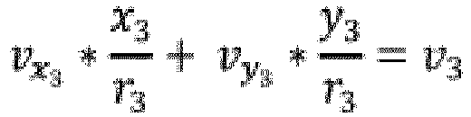

 (i) Vunbewegl.-Kand.-x die in Frage kommende Projektion der Geschwindigkeit eines unbeweglichen Objekts auf der Mittelachse ist, und(ii) Vunbewegl.-Kand.-y die in Frage kommende Projektion der Geschwindigkeit eines unbeweglichen Objekts in der Richtung senkrecht zur aktuellen Mittelachse ist.
 - Verfahren (700) nach einem der Ansprüche 1-10, wobei das Bestimmen des Winkelversatzes (550) des Radarsystems (230) als Reaktion darauf ausgeführt wird, dass die Teilmenge von detektierten Objekten mindestens eines der Folgenden einschließt:• mindestens einen vorgegebenen Anteil von detektierten Objekten der Vielzahl von detektierten Objekten; und• mindestens eine vorgegebene Anzahl von detektierten Objekten.
- Verfahren (700) nach einem der Ansprüche 1-11, wobei (i) das Empfangen der Radardaten (650), (ii) das Bestimmen von Projektionen der Geschwindigkeit eines unbeweglichen Objekts und (iii) das Bestimmen des Winkelversatzes (550) von der Computervorrichtung zu (i) einem ersten Zeitpunkt, und (ii) einem zweiten Zeitpunkt nach dem ersten Zeitpunkt wiederholt ausgeführt werden, und wobei das Verfahren (700) gegebenenfalls ferner Folgendes umfasst:• Durchführen, durch die Computervorrichtung, einer extrinsischen Kalibrierung des Radarsystems (230) zu dem ersten Zeitpunkt auf Grundlage des Winkelversatzes (550), der zum ersten Zeitpunkt bestimmt wurde; und• Durchführen, durch die Computervorrichtung, einer extrinsischen Kalibrierung des Radarsystems (230) zu dem zweiten Zeitpunkt auf Grundlage des Winkelversatzes (550), der zum zweiten Zeitpunkt bestimmt wurde.
- Verfahren (700) nach einem der Ansprüche 1-12, wobei das Bestimmen der Projektionen der Geschwindigkeit eines unbeweglichen Objekts Folgendes umfasst:
iteratives Bestimmen, durch die Computervorrichtung, von in Frage kommenden Projektionen auf Grundlage der punktspezifischen Daten von jeweiligen iterativ verkleinerten Sätzen von detektierten Objekten. - Verfahren nach Anspruch 13, wobei detektierte Objekte aus der Teilmenge von detektierten Objekten im Wesentlichen ähnliche Bewegungsmuster in Bezug auf das Radarsystem (230) aufweisen, wobei das Bewegungsmuster in Bezug auf die Oberfläche unbeweglich ist oder sich das Bewegungsmuster mit einer im Wesentlichen gleichen Geschwindigkeit in eine Richtung bewegt, die der Vorwärtsfahrtrichtung entgegengesetzt ist.
Applications Claiming Priority (1)
| Application Number | Priority Date | Filing Date | Title |
|---|---|---|---|
| RU2018147498A RU2742323C2 (ru) | 2018-12-29 | 2018-12-29 | Способ и компьютерное устройство для определения углового смещения радиолокационной системы |
Publications (2)
| Publication Number | Publication Date |
|---|---|
| EP3674746A1 EP3674746A1 (de) | 2020-07-01 |
| EP3674746B1 true EP3674746B1 (de) | 2021-07-07 |
Family
ID=68583286
Family Applications (1)
| Application Number | Title | Priority Date | Filing Date |
|---|---|---|---|
| EP19209592.5A Active EP3674746B1 (de) | 2018-12-29 | 2019-11-15 | Verfahren und computervorrichtungen zur bestimmung des winkelversatzes eines radarsystems |
Country Status (4)
| Country | Link |
|---|---|
| US (1) | US11402467B2 (de) |
| EP (1) | EP3674746B1 (de) |
| IL (1) | IL270456A (de) |
| RU (1) | RU2742323C2 (de) |
Families Citing this family (6)
| Publication number | Priority date | Publication date | Assignee | Title |
|---|---|---|---|---|
| KR102644368B1 (ko) * | 2018-09-06 | 2024-03-07 | 현대자동차주식회사 | 레이더 센서의 타겟 각도 오차 보정 방법과 이를 이용한 레이더 감지 장치 |
| US11686836B2 (en) * | 2020-01-13 | 2023-06-27 | Pony Ai Inc. | Real-time and dynamic localization using active doppler sensing systems for vehicles |
| US11454701B2 (en) * | 2020-01-13 | 2022-09-27 | Pony Ai Inc. | Real-time and dynamic calibration of active sensors with angle-resolved doppler information for vehicles |
| CN113534156B (zh) * | 2021-07-02 | 2024-04-05 | 中汽创智科技有限公司 | 一种基于车载毫米波雷达的车辆定位方法、装置及设备 |
| CN114397624B (zh) * | 2022-03-22 | 2022-07-15 | 北京蓝天航空科技股份有限公司 | 基于数据配置的兼容式雷达自检画面生成方法和装置 |
| KR20240145205A (ko) * | 2023-03-27 | 2024-10-07 | 주식회사 에이치엘클레무브 | 각도 보상 장치 및 방법과, 그를 포함하는 레이더 장치 |
Family Cites Families (41)
| Publication number | Priority date | Publication date | Assignee | Title |
|---|---|---|---|---|
| JP3331882B2 (ja) | 1995-12-27 | 2002-10-07 | 株式会社デンソー | 車両用障害物検出装置の中心軸偏向量算出装置,中心軸偏向量補正装置,および車間制御装置 |
| US5964822A (en) * | 1997-08-27 | 1999-10-12 | Delco Electronics Corp. | Automatic sensor azimuth alignment |
| US5977906A (en) | 1998-09-24 | 1999-11-02 | Eaton Vorad Technologies, L.L.C. | Method and apparatus for calibrating azimuth boresight in a radar system |
| GB2363016A (en) * | 2000-05-31 | 2001-12-05 | Roke Manor Research | Automotive radar |
| DE10149115A1 (de) * | 2001-10-05 | 2003-04-17 | Bosch Gmbh Robert | Objekterfassungsvorrichtung |
| US6927699B2 (en) | 2002-12-05 | 2005-08-09 | Denso Corporation | Object recognition apparatus for vehicle, and inter-vehicle distance control unit |
| US6972713B2 (en) | 2004-02-18 | 2005-12-06 | The Boeing Company | Method, apparatus, and computer program product for radar crossrange superresolution |
| US7071867B2 (en) | 2004-06-25 | 2006-07-04 | The Boeing Company | Method, apparatus, and computer program product for radar detection of moving target |
| DE102007018470A1 (de) * | 2007-04-19 | 2008-10-23 | Robert Bosch Gmbh | Fahrerassistenzsystem und Verfahren zur Objektplausibilisierung |
| DE102007062566A1 (de) * | 2007-12-22 | 2009-07-02 | Audi Ag | Kraftfahrzeug |
| SE533777C2 (sv) | 2009-05-14 | 2011-01-11 | Atlas Copco Rock Drills Ab | Förfarande för kalibrering av en ledvinkelsensor på ett fordon, förfarande för kalibrering av en avståndsskanner på ett fordon samt fordon |
| US9423498B1 (en) | 2012-09-25 | 2016-08-23 | Google Inc. | Use of motion data in the processing of automotive radar image processing |
| DE102013203574A1 (de) | 2013-03-01 | 2014-09-04 | Hella Kgaa Hueck & Co. | Verfahren zur Kompensation von Winkelmessfehlern |
| US9746554B2 (en) | 2013-04-09 | 2017-08-29 | Valeo Radar Systems, Inc. | Radar imaging system and related techniques |
| DE102013209494A1 (de) * | 2013-05-22 | 2014-11-27 | Robert Bosch Gmbh | Verfahren und Vorrichtung zum Ermitteln einer Dejustage eines Radarsensors eines Fahrzeugs |
| US9719801B1 (en) | 2013-07-23 | 2017-08-01 | Waymo Llc | Methods and systems for calibrating sensors using road map data |
| US20150070207A1 (en) | 2013-09-06 | 2015-03-12 | Valeo Radar Systems, Inc. | Method and Apparatus For Self Calibration of A Vehicle Radar System |
| DE102013021401A1 (de) * | 2013-12-18 | 2015-06-18 | Daimler Ag | Verfahren zur Bestimmung einer Einbauorientierung zumindest eines an einem Fahrzeug angeordneten Radarsensors |
| JP5976027B2 (ja) * | 2014-03-27 | 2016-08-23 | 三菱電機株式会社 | センサ軸ずれ検出装置およびセンサ軸ずれ検出方法 |
| US10024955B2 (en) * | 2014-03-28 | 2018-07-17 | GM Global Technology Operations LLC | System and method for determining of and compensating for misalignment of a sensor |
| US9733348B2 (en) | 2014-07-03 | 2017-08-15 | GM Global Technology Operations LLC | Vehicle radar with beam adjustment |
| US20160209211A1 (en) * | 2015-01-16 | 2016-07-21 | GM Global Technology Operations LLC | Method for determining misalignment of an object sensor |
| JP6520203B2 (ja) | 2015-02-25 | 2019-05-29 | 株式会社デンソー | 搭載角度誤差検出方法および装置、車載レーダ装置 |
| DE102015016888A1 (de) * | 2015-04-27 | 2016-10-27 | Günter Fendt | Umgebungserfassungssystem - autonomes Fahren - Justagefehler, bzw. Ausrichtungsfehler des Erfassungsbereiches des Umgebungserfassungssystems |
| KR102386670B1 (ko) | 2015-07-08 | 2022-04-14 | 엘지이노텍 주식회사 | 차량용 레이더의 자가 보정 장치 및 자가 보정 방법 |
| US10137904B2 (en) * | 2015-10-14 | 2018-11-27 | Magna Electronics Inc. | Driver assistance system with sensor offset correction |
| US9916703B2 (en) * | 2015-11-04 | 2018-03-13 | Zoox, Inc. | Calibration for autonomous vehicle operation |
| US9846228B2 (en) | 2016-04-07 | 2017-12-19 | Uhnder, Inc. | Software defined automotive radar systems |
| EP3239737B1 (de) * | 2016-04-29 | 2018-11-28 | Veoneer Sweden AB | Fehlausrichtungserkennung für einen fahrzeugradarsensor |
| US9952317B2 (en) | 2016-05-27 | 2018-04-24 | Uber Technologies, Inc. | Vehicle sensor calibration system |
| US10768298B2 (en) | 2016-06-14 | 2020-09-08 | Magna Electronics Inc. | Vehicle sensing system with 360 degree near range sensing |
| US10114106B2 (en) * | 2016-07-22 | 2018-10-30 | Delphi Technologies, Inc. | Automated vehicle radar system with auto-alignment for azimuth, elevation, and vehicle speed-scaling-error |
| DE102016216251B4 (de) | 2016-08-30 | 2023-09-21 | Audi Ag | Kraftfahrzeug zur Nutzung im Straßenverkehr und Verfahren zur Ermittlung einer Ausdehnung eines Fremdfahrzeugs in einem Kraftfahrzeug |
| US10481243B2 (en) | 2016-10-31 | 2019-11-19 | Aptiv Technologies Limited | Automated vehicle radar system with self-calibration |
| CN106772319B (zh) | 2016-12-19 | 2023-05-16 | 上海振华重工电气有限公司 | Agv激光防撞传感器偏转角自动标定装置及标定方法 |
| JP6551384B2 (ja) * | 2016-12-26 | 2019-07-31 | トヨタ自動車株式会社 | 車両用注意喚起装置 |
| DE102017201099A1 (de) | 2017-01-24 | 2018-07-26 | Conti Temic Microelectronic Gmbh | Verfahren zum Kalibrieren von Radarsensoren in einem Fahrzeug |
| US10545221B2 (en) * | 2017-05-23 | 2020-01-28 | Veoneer, Inc. | Apparatus and method for detecting alignment of sensor in an automotive detection system |
| EP3415943A1 (de) * | 2017-06-13 | 2018-12-19 | Veoneer Sweden AB | Fehlerschätzung für ein fahrzeugumgebungserkennungssystem |
| US10732262B2 (en) * | 2017-12-18 | 2020-08-04 | Veoneer Us, Inc. | Apparatus and method for detecting alignment of sensor in an automotive detection system |
| EP3588135B1 (de) * | 2018-06-28 | 2021-05-05 | Aptiv Technologies Limited | Verfahren zur bestimmung eines ausrichtungsfehlers einer antenne und fahrzeug mit einer antenne und einer detektionsvorrichtung |
-
2018
- 2018-12-29 RU RU2018147498A patent/RU2742323C2/ru active
-
2019
- 2019-09-10 US US16/565,886 patent/US11402467B2/en active Active
- 2019-11-05 IL IL270456A patent/IL270456A/en unknown
- 2019-11-15 EP EP19209592.5A patent/EP3674746B1/de active Active
Non-Patent Citations (1)
| Title |
|---|
| None * |
Also Published As
| Publication number | Publication date |
|---|---|
| EP3674746A1 (de) | 2020-07-01 |
| US20200209354A1 (en) | 2020-07-02 |
| RU2018147498A (ru) | 2020-06-29 |
| IL270456A (en) | 2020-06-30 |
| US11402467B2 (en) | 2022-08-02 |
| RU2018147498A3 (de) | 2020-07-22 |
| RU2742323C2 (ru) | 2021-02-04 |
Similar Documents
| Publication | Publication Date | Title |
|---|---|---|
| EP3674746B1 (de) | Verfahren und computervorrichtungen zur bestimmung des winkelversatzes eines radarsystems | |
| US10677907B2 (en) | Method to determine the orientation of a target vehicle | |
| US12235099B2 (en) | Axial deviation estimating device | |
| US11860315B2 (en) | Methods and systems for processing LIDAR sensor data | |
| EP4134627B1 (de) | Karteninformationskorrekturverfahren, fahrassistenzverfahren und karteninformationskorrekturvorrichtung | |
| US11860281B2 (en) | Methods and systems for filtering data points when merging LIDAR sensor datasets | |
| EP3842760B1 (de) | Verfahren und system zur erzeugung einer trajektorie für selbstfahrendes auto | |
| US12174301B2 (en) | Online validation of LIDAR-to-LIDAR alignment and LIDAR-to-vehicle alignment | |
| US12158520B2 (en) | Signal processing device, signal processing method, and information processing device | |
| US12044775B2 (en) | Methods and systems for detecting and mitigating automotive radar interference | |
| CN114488111B (zh) | 利用雷达数据估算车辆速度 | |
| WO2021070916A1 (ja) | 軸ずれ推定装置 | |
| US12061255B2 (en) | Scan matching and radar pose estimator for an autonomous vehicle based on hyper-local submaps | |
| US12017683B2 (en) | Method and device for operating a self-driving car | |
| US11353595B2 (en) | Sidelobe subtraction method in automotive radar signal processing | |
| US11543506B2 (en) | Method and computer device for calibrating LIDAR system | |
| US20240116506A1 (en) | Control calculation apparatus and control calculation method | |
| CN118444352B (zh) | 弱信号路段的无人机辅助车辆定位方法、装置及存储介质 | |
| US11754403B2 (en) | Self-position correction method and self-position correction device | |
| US12529774B2 (en) | Online LIDAR-to-ground alignment | |
| CN115704687B (zh) | 用于解析来自多种类型传感器的跟踪的遮挡约束 | |
| RU2792946C1 (ru) | Способ и компьютерное устройство для калибровки лидарной (lidar) системы | |
| EP4468034A1 (de) | Online-kalibrierung eines sensors | |
| US12606201B2 (en) | Vehicle control systems for controlling automated vehicle acceleration and braking | |
| JP2022115411A (ja) | 軸ずれ推定装置 |
Legal Events
| Date | Code | Title | Description |
|---|---|---|---|
| STAA | Information on the status of an ep patent application or granted ep patent |
Free format text: STATUS: EXAMINATION IS IN PROGRESS |
|
| PUAI | Public reference made under article 153(3) epc to a published international application that has entered the european phase |
Free format text: ORIGINAL CODE: 0009012 |
|
| 17P | Request for examination filed |
Effective date: 20191115 |
|
| AK | Designated contracting states |
Kind code of ref document: A1 Designated state(s): AL AT BE BG CH CY CZ DE DK EE ES FI FR GB GR HR HU IE IS IT LI LT LU LV MC MK MT NL NO PL PT RO RS SE SI SK SM TR |
|
| AX | Request for extension of the european patent |
Extension state: BA ME |
|
| RAP1 | Party data changed (applicant data changed or rights of an application transferred) |
Owner name: YANDEX SELF DRIVING GROUP LLC |
|
| GRAP | Despatch of communication of intention to grant a patent |
Free format text: ORIGINAL CODE: EPIDOSNIGR1 |
|
| STAA | Information on the status of an ep patent application or granted ep patent |
Free format text: STATUS: GRANT OF PATENT IS INTENDED |
|
| INTG | Intention to grant announced |
Effective date: 20210126 |
|
| GRAS | Grant fee paid |
Free format text: ORIGINAL CODE: EPIDOSNIGR3 |
|
| GRAA | (expected) grant |
Free format text: ORIGINAL CODE: 0009210 |
|
| STAA | Information on the status of an ep patent application or granted ep patent |
Free format text: STATUS: THE PATENT HAS BEEN GRANTED |
|
| AK | Designated contracting states |
Kind code of ref document: B1 Designated state(s): AL AT BE BG CH CY CZ DE DK EE ES FI FR GB GR HR HU IE IS IT LI LT LU LV MC MK MT NL NO PL PT RO RS SE SI SK SM TR |
|
| REG | Reference to a national code |
Ref country code: GB Ref legal event code: FG4D |
|
| REG | Reference to a national code |
Ref country code: AT Ref legal event code: REF Ref document number: 1409117 Country of ref document: AT Kind code of ref document: T Effective date: 20210715 |
|
| REG | Reference to a national code |
Ref country code: DE Ref legal event code: R096 Ref document number: 602019005934 Country of ref document: DE |
|
| REG | Reference to a national code |
Ref country code: IE Ref legal event code: FG4D |
|
| REG | Reference to a national code |
Ref country code: LT Ref legal event code: MG9D |
|
| REG | Reference to a national code |
Ref country code: NL Ref legal event code: MP Effective date: 20210707 |
|
| REG | Reference to a national code |
Ref country code: AT Ref legal event code: MK05 Ref document number: 1409117 Country of ref document: AT Kind code of ref document: T Effective date: 20210707 |
|
| PG25 | Lapsed in a contracting state [announced via postgrant information from national office to epo] |
Ref country code: FI Free format text: LAPSE BECAUSE OF FAILURE TO SUBMIT A TRANSLATION OF THE DESCRIPTION OR TO PAY THE FEE WITHIN THE PRESCRIBED TIME-LIMIT Effective date: 20210707 Ref country code: HR Free format text: LAPSE BECAUSE OF FAILURE TO SUBMIT A TRANSLATION OF THE DESCRIPTION OR TO PAY THE FEE WITHIN THE PRESCRIBED TIME-LIMIT Effective date: 20210707 Ref country code: NL Free format text: LAPSE BECAUSE OF FAILURE TO SUBMIT A TRANSLATION OF THE DESCRIPTION OR TO PAY THE FEE WITHIN THE PRESCRIBED TIME-LIMIT Effective date: 20210707 Ref country code: PT Free format text: LAPSE BECAUSE OF FAILURE TO SUBMIT A TRANSLATION OF THE DESCRIPTION OR TO PAY THE FEE WITHIN THE PRESCRIBED TIME-LIMIT Effective date: 20211108 Ref country code: NO Free format text: LAPSE BECAUSE OF FAILURE TO SUBMIT A TRANSLATION OF THE DESCRIPTION OR TO PAY THE FEE WITHIN THE PRESCRIBED TIME-LIMIT Effective date: 20211007 Ref country code: LT Free format text: LAPSE BECAUSE OF FAILURE TO SUBMIT A TRANSLATION OF THE DESCRIPTION OR TO PAY THE FEE WITHIN THE PRESCRIBED TIME-LIMIT Effective date: 20210707 Ref country code: BG Free format text: LAPSE BECAUSE OF FAILURE TO SUBMIT A TRANSLATION OF THE DESCRIPTION OR TO PAY THE FEE WITHIN THE PRESCRIBED TIME-LIMIT Effective date: 20211007 Ref country code: AT Free format text: LAPSE BECAUSE OF FAILURE TO SUBMIT A TRANSLATION OF THE DESCRIPTION OR TO PAY THE FEE WITHIN THE PRESCRIBED TIME-LIMIT Effective date: 20210707 Ref country code: RS Free format text: LAPSE BECAUSE OF FAILURE TO SUBMIT A TRANSLATION OF THE DESCRIPTION OR TO PAY THE FEE WITHIN THE PRESCRIBED TIME-LIMIT Effective date: 20210707 Ref country code: SE Free format text: LAPSE BECAUSE OF FAILURE TO SUBMIT A TRANSLATION OF THE DESCRIPTION OR TO PAY THE FEE WITHIN THE PRESCRIBED TIME-LIMIT Effective date: 20210707 Ref country code: ES Free format text: LAPSE BECAUSE OF FAILURE TO SUBMIT A TRANSLATION OF THE DESCRIPTION OR TO PAY THE FEE WITHIN THE PRESCRIBED TIME-LIMIT Effective date: 20210707 |
|
| PG25 | Lapsed in a contracting state [announced via postgrant information from national office to epo] |
Ref country code: PL Free format text: LAPSE BECAUSE OF FAILURE TO SUBMIT A TRANSLATION OF THE DESCRIPTION OR TO PAY THE FEE WITHIN THE PRESCRIBED TIME-LIMIT Effective date: 20210707 Ref country code: LV Free format text: LAPSE BECAUSE OF FAILURE TO SUBMIT A TRANSLATION OF THE DESCRIPTION OR TO PAY THE FEE WITHIN THE PRESCRIBED TIME-LIMIT Effective date: 20210707 Ref country code: GR Free format text: LAPSE BECAUSE OF FAILURE TO SUBMIT A TRANSLATION OF THE DESCRIPTION OR TO PAY THE FEE WITHIN THE PRESCRIBED TIME-LIMIT Effective date: 20211008 |
|
| REG | Reference to a national code |
Ref country code: DE Ref legal event code: R097 Ref document number: 602019005934 Country of ref document: DE |
|
| PG25 | Lapsed in a contracting state [announced via postgrant information from national office to epo] |
Ref country code: DK Free format text: LAPSE BECAUSE OF FAILURE TO SUBMIT A TRANSLATION OF THE DESCRIPTION OR TO PAY THE FEE WITHIN THE PRESCRIBED TIME-LIMIT Effective date: 20210707 |
|
| PLBE | No opposition filed within time limit |
Free format text: ORIGINAL CODE: 0009261 |
|
| STAA | Information on the status of an ep patent application or granted ep patent |
Free format text: STATUS: NO OPPOSITION FILED WITHIN TIME LIMIT |
|
| PG25 | Lapsed in a contracting state [announced via postgrant information from national office to epo] |
Ref country code: SM Free format text: LAPSE BECAUSE OF FAILURE TO SUBMIT A TRANSLATION OF THE DESCRIPTION OR TO PAY THE FEE WITHIN THE PRESCRIBED TIME-LIMIT Effective date: 20210707 Ref country code: SK Free format text: LAPSE BECAUSE OF FAILURE TO SUBMIT A TRANSLATION OF THE DESCRIPTION OR TO PAY THE FEE WITHIN THE PRESCRIBED TIME-LIMIT Effective date: 20210707 Ref country code: RO Free format text: LAPSE BECAUSE OF FAILURE TO SUBMIT A TRANSLATION OF THE DESCRIPTION OR TO PAY THE FEE WITHIN THE PRESCRIBED TIME-LIMIT Effective date: 20210707 Ref country code: EE Free format text: LAPSE BECAUSE OF FAILURE TO SUBMIT A TRANSLATION OF THE DESCRIPTION OR TO PAY THE FEE WITHIN THE PRESCRIBED TIME-LIMIT Effective date: 20210707 Ref country code: CZ Free format text: LAPSE BECAUSE OF FAILURE TO SUBMIT A TRANSLATION OF THE DESCRIPTION OR TO PAY THE FEE WITHIN THE PRESCRIBED TIME-LIMIT Effective date: 20210707 Ref country code: AL Free format text: LAPSE BECAUSE OF FAILURE TO SUBMIT A TRANSLATION OF THE DESCRIPTION OR TO PAY THE FEE WITHIN THE PRESCRIBED TIME-LIMIT Effective date: 20210707 |
|
| 26N | No opposition filed |
Effective date: 20220408 |
|
| PG25 | Lapsed in a contracting state [announced via postgrant information from national office to epo] |
Ref country code: MC Free format text: LAPSE BECAUSE OF FAILURE TO SUBMIT A TRANSLATION OF THE DESCRIPTION OR TO PAY THE FEE WITHIN THE PRESCRIBED TIME-LIMIT Effective date: 20210707 |
|
| PG25 | Lapsed in a contracting state [announced via postgrant information from national office to epo] |
Ref country code: LU Free format text: LAPSE BECAUSE OF NON-PAYMENT OF DUE FEES Effective date: 20211115 Ref country code: IT Free format text: LAPSE BECAUSE OF FAILURE TO SUBMIT A TRANSLATION OF THE DESCRIPTION OR TO PAY THE FEE WITHIN THE PRESCRIBED TIME-LIMIT Effective date: 20210707 Ref country code: BE Free format text: LAPSE BECAUSE OF NON-PAYMENT OF DUE FEES Effective date: 20211130 |
|
| REG | Reference to a national code |
Ref country code: BE Ref legal event code: MM Effective date: 20211130 |
|
| PG25 | Lapsed in a contracting state [announced via postgrant information from national office to epo] |
Ref country code: IE Free format text: LAPSE BECAUSE OF NON-PAYMENT OF DUE FEES Effective date: 20211115 |
|
| P01 | Opt-out of the competence of the unified patent court (upc) registered |
Effective date: 20230521 |
|
| PG25 | Lapsed in a contracting state [announced via postgrant information from national office to epo] |
Ref country code: CY Free format text: LAPSE BECAUSE OF FAILURE TO SUBMIT A TRANSLATION OF THE DESCRIPTION OR TO PAY THE FEE WITHIN THE PRESCRIBED TIME-LIMIT Effective date: 20210707 |
|
| REG | Reference to a national code |
Ref country code: CH Ref legal event code: PL |
|
| PG25 | Lapsed in a contracting state [announced via postgrant information from national office to epo] |
Ref country code: LI Free format text: LAPSE BECAUSE OF NON-PAYMENT OF DUE FEES Effective date: 20221130 Ref country code: HU Free format text: LAPSE BECAUSE OF FAILURE TO SUBMIT A TRANSLATION OF THE DESCRIPTION OR TO PAY THE FEE WITHIN THE PRESCRIBED TIME-LIMIT; INVALID AB INITIO Effective date: 20191115 Ref country code: CH Free format text: LAPSE BECAUSE OF NON-PAYMENT OF DUE FEES Effective date: 20221130 |
|
| REG | Reference to a national code |
Ref country code: DE Ref legal event code: R081 Ref document number: 602019005934 Country of ref document: DE Owner name: DIRECT CURSUS TECHNOLOGY L.L.C., AE Free format text: FORMER OWNER: YANDEX SELF DRIVING GROUP LLC, MOSCOW, RU Ref country code: DE Ref legal event code: R081 Ref document number: 602019005934 Country of ref document: DE Owner name: Y. E. HUB ARMENIA LLC, AM Free format text: FORMER OWNER: YANDEX SELF DRIVING GROUP LLC, MOSCOW, RU |
|
| REG | Reference to a national code |
Ref country code: GB Ref legal event code: 732E Free format text: REGISTERED BETWEEN 20231214 AND 20231220 |
|
| PG25 | Lapsed in a contracting state [announced via postgrant information from national office to epo] |
Ref country code: MK Free format text: LAPSE BECAUSE OF FAILURE TO SUBMIT A TRANSLATION OF THE DESCRIPTION OR TO PAY THE FEE WITHIN THE PRESCRIBED TIME-LIMIT Effective date: 20210707 |
|
| PG25 | Lapsed in a contracting state [announced via postgrant information from national office to epo] |
Ref country code: MT Free format text: LAPSE BECAUSE OF FAILURE TO SUBMIT A TRANSLATION OF THE DESCRIPTION OR TO PAY THE FEE WITHIN THE PRESCRIBED TIME-LIMIT Effective date: 20210707 |
|
| REG | Reference to a national code |
Ref country code: GB Ref legal event code: 732E Free format text: REGISTERED BETWEEN 20241114 AND 20241120 |
|
| REG | Reference to a national code |
Ref country code: DE Ref legal event code: R081 Ref document number: 602019005934 Country of ref document: DE Owner name: Y. E. HUB ARMENIA LLC, AM Free format text: FORMER OWNER: DIRECT CURSUS TECHNOLOGY L.L.C., DUBAI, AE Ref country code: DE Ref legal event code: R082 Ref document number: 602019005934 Country of ref document: DE |
|
| PG25 | Lapsed in a contracting state [announced via postgrant information from national office to epo] |
Ref country code: TR Free format text: LAPSE BECAUSE OF FAILURE TO SUBMIT A TRANSLATION OF THE DESCRIPTION OR TO PAY THE FEE WITHIN THE PRESCRIBED TIME-LIMIT Effective date: 20210707 |
|
| PGFP | Annual fee paid to national office [announced via postgrant information from national office to epo] |
Ref country code: DE Payment date: 20251022 Year of fee payment: 7 |
|
| PGFP | Annual fee paid to national office [announced via postgrant information from national office to epo] |
Ref country code: GB Payment date: 20251023 Year of fee payment: 7 |
|
| PGFP | Annual fee paid to national office [announced via postgrant information from national office to epo] |
Ref country code: FR Payment date: 20251022 Year of fee payment: 7 |