EP3674764B1 - Boîtier destiné à être utilisé dans un réseau de distribution à fibres optiques - Google Patents
Boîtier destiné à être utilisé dans un réseau de distribution à fibres optiques Download PDFInfo
- Publication number
- EP3674764B1 EP3674764B1 EP20151309.0A EP20151309A EP3674764B1 EP 3674764 B1 EP3674764 B1 EP 3674764B1 EP 20151309 A EP20151309 A EP 20151309A EP 3674764 B1 EP3674764 B1 EP 3674764B1
- Authority
- EP
- European Patent Office
- Prior art keywords
- cable
- gasket
- enclosure
- port
- port size
- Prior art date
- Legal status (The legal status is an assumption and is not a legal conclusion. Google has not performed a legal analysis and makes no representation as to the accuracy of the status listed.)
- Active
Links
Images










Classifications
-
- G—PHYSICS
- G02—OPTICS
- G02B—OPTICAL ELEMENTS, SYSTEMS OR APPARATUS
- G02B6/00—Light guides; Structural details of arrangements comprising light guides and other optical elements, e.g. couplings
- G02B6/44—Mechanical structures for providing tensile strength and external protection for fibres, e.g. optical transmission cables
- G02B6/4439—Auxiliary devices
- G02B6/444—Systems or boxes with surplus lengths
- G02B6/4441—Boxes
- G02B6/44515—Fibre drop terminals with surplus length
-
- F—MECHANICAL ENGINEERING; LIGHTING; HEATING; WEAPONS; BLASTING
- F16—ENGINEERING ELEMENTS AND UNITS; GENERAL MEASURES FOR PRODUCING AND MAINTAINING EFFECTIVE FUNCTIONING OF MACHINES OR INSTALLATIONS; THERMAL INSULATION IN GENERAL
- F16J—PISTONS; CYLINDERS; SEALINGS
- F16J15/00—Sealings
- F16J15/02—Sealings between relatively-stationary surfaces
- F16J15/06—Sealings between relatively-stationary surfaces with solid packing compressed between sealing surfaces
- F16J15/062—Sealings between relatively-stationary surfaces with solid packing compressed between sealing surfaces characterised by the geometry of the seat
-
- F—MECHANICAL ENGINEERING; LIGHTING; HEATING; WEAPONS; BLASTING
- F16—ENGINEERING ELEMENTS AND UNITS; GENERAL MEASURES FOR PRODUCING AND MAINTAINING EFFECTIVE FUNCTIONING OF MACHINES OR INSTALLATIONS; THERMAL INSULATION IN GENERAL
- F16J—PISTONS; CYLINDERS; SEALINGS
- F16J15/00—Sealings
- F16J15/02—Sealings between relatively-stationary surfaces
- F16J15/06—Sealings between relatively-stationary surfaces with solid packing compressed between sealing surfaces
- F16J15/08—Sealings between relatively-stationary surfaces with solid packing compressed between sealing surfaces with exclusively metal packing
- F16J15/0887—Sealings between relatively-stationary surfaces with solid packing compressed between sealing surfaces with exclusively metal packing the sealing effect being obtained by elastic deformation of the packing
-
- G—PHYSICS
- G02—OPTICS
- G02B—OPTICAL ELEMENTS, SYSTEMS OR APPARATUS
- G02B6/00—Light guides; Structural details of arrangements comprising light guides and other optical elements, e.g. couplings
- G02B6/44—Mechanical structures for providing tensile strength and external protection for fibres, e.g. optical transmission cables
- G02B6/4439—Auxiliary devices
- G02B6/444—Systems or boxes with surplus lengths
- G02B6/4441—Boxes
- G02B6/4442—Cap coupling boxes
- G02B6/4444—Seals
-
- G—PHYSICS
- G02—OPTICS
- G02B—OPTICAL ELEMENTS, SYSTEMS OR APPARATUS
- G02B6/00—Light guides; Structural details of arrangements comprising light guides and other optical elements, e.g. couplings
- G02B6/44—Mechanical structures for providing tensile strength and external protection for fibres, e.g. optical transmission cables
- G02B6/4439—Auxiliary devices
- G02B6/444—Systems or boxes with surplus lengths
- G02B6/4441—Boxes
- G02B6/4446—Cable boxes, e.g. splicing boxes with two or more multi fibre cables
- G02B6/44465—Seals
-
- G—PHYSICS
- G02—OPTICS
- G02B—OPTICAL ELEMENTS, SYSTEMS OR APPARATUS
- G02B6/00—Light guides; Structural details of arrangements comprising light guides and other optical elements, e.g. couplings
- G02B6/44—Mechanical structures for providing tensile strength and external protection for fibres, e.g. optical transmission cables
- G02B6/4439—Auxiliary devices
- G02B6/4471—Terminating devices ; Cable clamps
- G02B6/44765—Terminating devices ; Cable clamps with means for strain-relieving to exterior cable layers
-
- G—PHYSICS
- G02—OPTICS
- G02B—OPTICAL ELEMENTS, SYSTEMS OR APPARATUS
- G02B6/00—Light guides; Structural details of arrangements comprising light guides and other optical elements, e.g. couplings
- G02B6/44—Mechanical structures for providing tensile strength and external protection for fibres, e.g. optical transmission cables
- G02B6/4439—Auxiliary devices
- G02B6/4471—Terminating devices ; Cable clamps
- G02B6/44775—Cable seals e.g. feed-through
-
- H—ELECTRICITY
- H02—GENERATION; CONVERSION OR DISTRIBUTION OF ELECTRIC POWER
- H02G—INSTALLATION OF ELECTRIC CABLES OR LINES, OR OF COMBINED OPTICAL AND ELECTRIC CABLES OR LINES
- H02G15/00—Cable fittings
- H02G15/007—Devices for relieving mechanical stress
-
- H—ELECTRICITY
- H02—GENERATION; CONVERSION OR DISTRIBUTION OF ELECTRIC POWER
- H02G—INSTALLATION OF ELECTRIC CABLES OR LINES, OR OF COMBINED OPTICAL AND ELECTRIC CABLES OR LINES
- H02G15/00—Cable fittings
- H02G15/013—Sealing means for cable inlets
Definitions
- the present disclosure relates generally to enclosures. More particularly, the present disclosure relates to sealed, re-enterable enclosures used in fiber optic distribution networks.
- Fiber optic distribution networks are becoming prevalent in part because service providers want to deliver high bandwidth communication capabilities to customers (i.e., subscribers).
- Fiber to the x refers to any broadband network architecture that uses optical fiber to provide all or part of the local loop used for last mile telecommunications. More specific broadband network architectures include fiber to the curb (FTTC), fiber to the distribution point (FTTdp), fiber to the premises (FTTP) and fiber to the desktop (FTTD).
- Typical fiber optic network architectures include a plurality of fiber optic cables distributed outwardly from a central location (e.g., a central office) toward subscriber locations.
- sealed and re-enterable enclosures can be used to provide access to the optical fibers of the network distribution cables.
- multi-fiber distribution cables are passed through the enclosures and optical fibers of the cables are accessed within the enclosures.
- Splice trays, passive optical splitters and wave length division multiplexers can be provided within the enclosures.
- optical fibers accessed from distribution cables can be coupled to optical components (e.g., a passive optical splitter or a wavelength division multiplexer) and outputs from the optical components can be coupled to drop cables routed from the enclosures.
- the enclosures can include ruggedized adapter ports for allowing pre-connectorized drop cables to be connected to the fibers accessed from the distribution cables.
- fibers of the distribution cable can be spliced to optical fibers corresponding to drop cables routed out of the enclosure through sealed ports.
- Example enclosures of the type described above are disclosed at US Patent Nos. 8,213,760 ; 8,718,434 ; and 7,013,074 . Further relevant prior art is disclosed in the following patent applications: US 2007/007038 A1 , FR 2 758 400 A1 and US 2007/025677 A1 .
- Effective sealing is an important consideration relating to sealed, re-enterable outdoor enclosures used in fiber optic distribution networks. Aspects of the present disclosure relate to enhanced sealing configurations for providing effective sealing of enclosures.
- Certain aspects of the present disclosure relate to sealing configurations for effectively sealing triple points of an enclosure.
- One aspect of the present disclosure relates to an elastomeric cable seal having a main body and sealing tabs adapted for enhancing effective sealing at triple points formed at an interface between the main body and a housing of the enclosure.
- the tabs can be tapered along their lengths so as to narrow as the tabs extend away from the main body of the cable seal.
- the tabs are at a top end of the cable seal.
- Another aspect of the present disclosure relates to an elastomeric sealing member having a chamfered peripheral surface that provides an enhanced sealing at a triple point between the sealing member and a housing of the enclosure.
- FIG. 1 For purposes of this regard, it is desirable to provide effective perimeter sealing without requiring excessive clamping pressures between the housing pieces and without requiring an excessive number of clamps or other fasteners provided about the perimeter of the enclosure.
- Certain aspects of the present disclosure relate to a perimeter sealing gasket having a transverse cross-sectional profile including an elongated web that is compressed along its length and that includes radial sealing ribs that project laterally outwardly from opposite sides of the web.
- ribs of the web can include enlarged, rounded heads.
- the transverse cross-sectional profile includes open space or voids on both sides of the web that assist in allowing the sealing gasket to be compressed at lower compression forces.
- the transverse cross-sectional profile is compressed at least 1 millimeter or at least 1.5 millimeters along the length of the web.
- the transverse cross-sectional profile is compressed at least 15, 20 or 25 percent along the length of the web from a non-compressed state to a compressed state when the housing pieces are latched together.
- the transverse cross-sectional profile is compressed at least 15-25 percent along the length of the web from a non-compressed state to a compressed state when the housing pieces are latched together.
- the gasket can have a Shore A hardness in the range of 20-60.
- aspects of the present disclosure relate to port size reducers having an integrated configuration in which multiple functions can be provided by one port size reducer.
- port size reducers in accordance with the principles of the present disclosure can provide port size reducing functions, cable sealing functions and cable clamping functions.
- Other aspects of the present disclosure relate to blind plugs that are multi-functional.
- certain blind plugs in accordance with the principles of the present disclosure can provide port closing functionality and can also interface with a cable anchoring station for assisting in anchoring fiber optic cables to an enclosure.
- aspects of the present disclosure relate to enclosures having perimeter sealing that provides effective sealing at relatively low compression levels. Another aspect of the present disclosure relates to cable seal configurations that provide enhanced sealing at triple point locations defined between housing pieces of the enclosure. Still another aspect of the present disclosure relates to elongated, multifunction port size reducers and blind plugs adapted to reduce the part count and complexity of the enclosure.
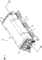
- FIG. 1 illustrates an enclosure 20 in accordance with the principles of the present disclosure suitable for use in a fiber optic distribution network.
- the enclosure 20 includes a housing 22 having a first housing piece 24 (e.g., a base) and a second housing piece 26 (e.g., a cover).
- the first and second housing pieces 24, 26 are configured to be coupled together to define a housing interior 28 (see Fig. 2 ).
- the first and second housing pieces 24, 26 interface with one another (e.g., mate together, engage one another, etc.) at an interface location 30 that extends about a perimeter P of the housing 22.
- a gasket 32 provides a perimeter seal between the first housing piece 24 and the second housing piece 26.
- the gasket 32 is positioned between the first and second housing pieces 24, 26 at the interface location 30.
- the first housing piece 24 defines a plurality of cable seal openings 34 in which cable seals 36 are mounted.
- Cable anchoring stations 38 i.e., locations
- the cable anchoring stations 38 include cable clamping locations 40 positioned in alignment with the cable seal openings 34.
- Port size reducer plugs 42a, 42b are shown mounted within major cable ports 44 defined by the cable seals 36.
- the port size reducer plugs 42a, 42b respectively define minor cable ports 46a, 46b.
- Blind plugs 48a, 48b are respectively mounted within the minor cable ports 46a, 46b.
- the port size reducer plugs 42a, 42b and the blind plugs 48a, 48b are constructed to perform multiple functions and include portions that interact with the cable seals 36 and portions that interact with the cable anchoring stations 38.
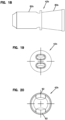
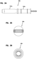
- the port size reducer plugs 42a, 42b are elongated and each has a molded, monolithic, one-piece construction.
- the blind plugs 48a, 48b are also elongated and can each have a molded, monolithic, one-piece construction.
- first and second housing pieces 24, 26 can be pivotally connected at a hinge 50 that extends along a major side of the housing 22.
- Clamping latches 52 can be used to secure (e.g., clamp, fix or otherwise retain) the first and second housing pieces 24, 26 together.
- single clamping latches 52 are provided at minor sides of the housing 22 and a plurality of clamping latches 52 are provided at a major side of the housing 22 that is opposite from the hinge 50.
- a stack of pivotal fiber management trays 54 is shown mounted within the first housing piece 24.
- the fiber management trays 54 can include fiber routing paths for routing excess optical fiber in looped configurations that prevent the optical fiber from being bent beyond minimum bend radius requirements.
- the fiber management trays 54 can also function as splice holders for holding a plurality of splices. Additionally, the fiber management trays 54 can retain and protect fiber optic components such as passive optical splitters and/or wavelength division multiplexers.
- the ruggedized fiber optic adapters 56 include exterior ports 58 and interior ports 60.
- the exterior ports 58 are adapted to receive ruggedized fiber optic connectors corresponding to pre-connectorized drop cables.
- the exterior ports 58 are enclosed by dust plugs 62 and are environmentally sealed. By removing the dust plugs 62, the ruggedized fiber optic connectors corresponding to the pre-connectorized drop cables can be inserted into the exterior ports 58.
- a sealed relationship exists between the ruggedized fiber optic connectors and the exterior ports 58 of their corresponding ruggedized fiber optic adapters 56.
- a robust coupling technique e.g., a threaded coupling, a bayonet style coupling or other like type of coupling
- the interior ports 60 of the ruggedized fiber optic adapters 56 receive connectorized ends 64 of connectorized pigtails 66.
- the ruggedized fiber optic connectors are inserted within the exterior ports 58 of the ruggedized fiber optic adapters 56, the ruggedized fiber optic connectors are optically coupled to the connectorized ends 64 of the corresponding connectorized pigtails 66. It will be appreciated that a sealed relationship exists between the ruggedized fiber optic adapters 56 and the housing 22. Similarly, a sealed interface exists between the ruggedized fiber optic connectors and the ruggedized fiber optic adapters 56.
- a multi-fiber distribution cable such as a trunk cable can be passed through the interior of the enclosure by routing the trunk cable through the major cable ports 44 defined by the cable seals 36.
- the portion of the distribution cable within the housing interior 28 can be subjected to a window-cutting operation in which the outer jacket is removed to provide access to the optical fibers of the distribution cable. Selected ones of the optical fibers can be accessed, cut and optically coupled to smaller cables (e.g., drop cables) routed from the enclosure 20 through the port size reducers.
- the accessed fibers can be routed to the fiber management trays 54 and spliced to optical fibers corresponding to drop cables routed out of the enclosure 20 through the minor cable ports 46a, 46b defined by the port size reducer plugs 42a, 42b.
- the accessed optical fibers can be routed to the fiber management trays 54 and spliced to the connectorized pigtails 66 having the connectorized ends 64 inserted within the interior ports 60 of the ruggedized fiber optic adapters 56.
- the optical fibers accessed from the pass-through cable can be routed to the fiber management trays 54 and optically coupled to fiber optic components supported on the fiber management trays 54 such as passive optical splitters or wavelength division multiplexers.
- optical outputs of such fiber optic components can be optically coupled to the connectorized pigtails 66 having connectorized ends 64 inserted within the interior ports 60 of the ruggedized fiber optic adapters 56 or can be optically coupled to optical fibers corresponding to cables routed out of the enclosure 20 through the minor cable ports 46a, 46b.
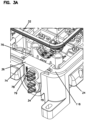
- the cable anchoring stations 38 can include a plurality of clamping elements 68 that can cooperate to define the cable clamping locations 40.
- the clamping elements 68 can be stacked on top of one another and fastened together using fastening elements.
- the fastening elements can include fasteners such as bolts 70.
- the clamping elements 68 can include lower clamping elements 68a that are integrated with the first housing piece 24.
- the clamping elements 68 can also include intermediate clamping elements 68b fastened to the lower clamping elements 68a, and upper clamping elements 68c fastened to the intermediate clamping elements 68b.
- the cable clamping locations 40 can be provided at clamping pockets or receptacles 72 defined between the clamping elements 68.
- the clamping pockets 72 can be relatively large in size and can be configured for receiving relatively large cables such as the trunk cables that are passed through the enclosure 20. It will be appreciated that the clamping pockets 72 are generally co-axially aligned with the major cable ports 44 defined by the cable seals 36.
- the cable seals 36, the gasket 32 and the port reducing plugs 42a, 42b can all have resilient, elastomeric constructions.
- the various sealing components can have a polymeric construction, a rubber construction or a rubber-like construction.
- the sealing elements can be compressible and can be configured to elastically deform to fill voids for sealing purposes.
- the cable seals 36 mount at the cable seal openings 34 of the first housing piece 24.
- the cable seal openings 34 can be configured to effectively retain the cable seals 36.
- the cable seal openings 34 can define seal retention pockets 74 defined by inner and outer flanges 76, 78.
- the inner and outer flanges 76, 78 overlap the cable seals 36 such that the cable seals 36 are effectively retained within the cable seal openings 34.
- the cable seals 36 can include slit or tear locations 79 so as to function as wrap-around seals for allowing cables to be laterally inserted into the major cable ports 44.
- the major cable ports 44 defined by the cable seals 36 are configured to receive round, relatively large fiber optic cables. Examples of this type of cable include multi-fiber distribution cables of the type typically passed through the enclosure 20.
- the port size reducer plugs 42a, 42b can function as port size converters for allowing the cable seals 36 to accommodate smaller cables. For example, when the port size reducer plugs 42a, 42b are inserted within the major cable ports 44 of the cable seals 36, a sealed relationship exists between the exterior of the port size reducer plugs 42a, 42b and the cable seals 36.
- the minor cable ports 46a, 46b are configured for receiving and sealing smaller cables such as drop cables.
- the minor cable ports 46a are adapted for receiving round cables while the minor cable ports 46b are adapted for receiving flat cables.
- the blind plugs 48a, 48b are configured to plug and seal the minor cable ports 46a, 46b when the minor cable ports 46a, 46b are not occupied by cables.
- the corresponding blind plug 48a, 48b is removed thereby allowing for the insertion of the corresponding cable through the corresponding minor cable port 46a, 46b.
- each of the port size reducer plugs 42a, 42b has a one-piece construction with different sections (e.g., portions, regions, extents) configured to perform different functions with respect to the enclosure 20.
- the different functions can include port size reducing functions, cable sealing functions and cable anchoring functions.
- the minor cable ports 46a, 46b can extend through lengths of the port size reducer plugs 42a, 42b.
- the port size reducer plugs 42a, 42b can include first portions 80a, 80b and second portions 82a, 82b positioned along the lengths of the port size reducer plugs 42a, 42b.
- the port size reducer plugs 42a, 42b are sized in shape such that the first portions 80a, 80b are configured to fit in a sealed relationship within the major cable ports 44.
- the second portions 82a, 82b of the port size reducer plugs 42a, 42b are configured to fit within the clamping pockets 72 defined at the clamping locations 40 of the cable anchoring stations 38.
- the first portions 80a, 80b of the port size reducer plugs 42a, 42b function as port size converters for converting the cable seals 36 to accommodate smaller cables.
- the first portions 80a, 80b can fill the major cable ports 44 of the cable seals 36 and can include exterior surfaces that make sealed contact with the interior of the cable seals 36.
- the minor cable ports 46a, 46b can have transverse cross-sectional shapes that are fully enclosed at the first portions 80a, 80b so as to provide uninterrupted sealing about the exterior surface of a cable (e.g., a drop cable) routed therethrough.
- the first portions 80a, 80b of the port size reducer plugs 42a, 42b can have truncated conical shapes having major ends 84 and minor ends 86.
- the truncated conical shapes of the first portions 80a, 80b can match corresponding truncated conical shapes of the major cable ports 44.
- the port size reducer plugs 42a, 42b can include first and second retention shoulders 88, 90 positioned adjacent to the major and minor ends 84, 86 of the truncated conical shapes of the first portions 80a, 80b.
- the first and second retention shoulders 88, 90 can engage inner and outer faces of the cable seals 36 to provide for axial retention of the port size reducer plugs 42a, 42b within the cable seals 36.
- the second portions 82a, 82b of the port size reducer plugs 42a, 42b are adapted to assist in providing an effective clamping function at the cable anchoring stations 38 for smaller cables.
- the second portions 82a, 82b are configured to fit within the clamping pockets 72 and to assist in clamping drop cables routed through the minor cable ports 46a, 46b within the clamping pockets 72. Absent the presence of the second portions 82a, 82b, the clamping pockets 72 would be too large to provide effective clamping of the relatively small cables routed through the minor cable ports 46a, 46b.
- the second portions 82a, 82b are configured to fill excess void space within the clamping pockets 72 so that the relatively small cables routed through the minor cable ports 46a, 46b can be effectively clamped at the cable anchoring stations 38.
- the second portions 82a, 82b of the port size reducer plugs 42a, 42b can be generally cylindrical in shape and can be unitarily formed with the first portions 80a, 80b adjacent the minor ends 86 of the truncated conical shapes defined by the first portions 80a, 80b.
- the second portions 82a, 82b are configured to generally fill the clamping pockets 72 and are depicted having open sides 92. The open sides 92 allow the clamping elements 68 to directly contact cables routed through the port size reducer plugs 42a, 42b so as to provide direct clamping force upon the jackets of the cables routed through the port size reducer plugs 42a, 42b.
- the blind plugs 48a, 48b are configured to fit within the minor cable ports 46a, 46b.
- the blind plugs 48a, 48b are configured to effectively seal the minor cable ports 46a, 46b when the cable ports 46a, 46b are not occupied by cables.
- the blind plugs 48a, 48b are also configured to assist in providing effective clamping at the cable anchoring stations 38.
- the blind plugs 48a have elongated transverse cross-sectional shapes that correspond to the shapes of the minor cable ports 46a, and the blind plugs 48b have round transverse cross-sectional shapes that correspond to the shapes of the minor cable ports 46b.
- Each of the blind plugs 48a, 48b has an elongated construction having an outer end with a handle 100a, 100b.
- Each of the blind plugs 48a, 48b also includes a first extent 102a, 102b that coincides with the first portion 80a, 80b of the port reducing plug 42a, 42b, and a second extent 104a, 104b that coincides with the second portion 82a, 82b of the port size reducer plug 42a, 42b.
- the first extents 102a, 102b fill the minor cable ports 46a, 46b at the first portions 80a, 80b so as to effectively seal and close the minor cable ports 46a, 46b when the minor cable ports 46a, 46b are not in use.
- the second extents 104a, 104b effectively fill the minor cable ports 46a, 46b at the second portions 82a, 82b of the port reducing plugs 42a, 42b so as to limit void space within the second portions 82a, 82b so that the second portions 82a, 82b do not excessively deform during clamping.
- the unoccupied minor cable port 46a, 46b would allow the second portion 82a, 82b to deform a substantial amount during clamping thereby preventing sufficient clamping force from being applied to the cable routed through the other minor cable port 46a, 46b.
- the blind plugs 48a, 48b can also include first retention shoulders 106a, 106b positioned adjacent the handles 100a, 100b and second retention shoulders 108a, 108b positioned between the first extents 102a, 102b and the second extents 104a, 104b.
- the first retention shoulders 106a, 106b and the second retention shoulders 108a, 108b provide for effective axial retention of the blind plugs 48a, 48b within their corresponding minor cable ports 46a, 46b.
- the gasket 32 of the enclosure 20 is adapted to provide a perimeter seal at the interface between the first and second housing pieces 24, 26.
- the first and second housing pieces can have a mating relationship at the interface location 30.
- the second housing piece 26 can include channels 110 at the ends of the housing that receive rails 111 of the first housing piece 24 such that the second housing piece 26 nests over the first housing piece 24 to provide effective mating and alignment between the first and second housing pieces 24, 26.
- the second housing piece 26 can also include a lip that overhangs the first housing piece 24 along the major sides of the enclosure 20.
- the interface location 30 also includes gasket engagement and compression surfaces for causing compression of the gasket 32 when the first and second housing pieces 24, 26 are mated and clamped together.
- the second housing piece 26 defines a channel 112 in which the gasket 32 is received.
- the channel 112 includes a gasket engagement surface 114 that opposes a corresponding gasket engagement surface 116 of the first housing piece 24.
- the gasket 32 is compressed between the gasket engagement surfaces 114, 116.
- the gasket 32 Prior to compression, the gasket 32 has a height H that is larger than the depth of the channel 112.
- the gasket 32 has a transverse cross-sectional shape including a web 120 having a length L that extends between first and second ends 122, 124 of the web 120.
- the web 120 includes first and second sides 126, 128 that extend along the length L between the first and second ends 122, 124.
- the transverse cross-sectional shape has enlarged heads 130 at the first and second ends 122, 124.
- the transverse cross-sectional shape also has first ribs 132 that project outwardly from the first side 126 of the web 120 at a location between the enlarged heads 130, and second ribs 134 that project outwardly from the second side 128 of the web 120 at a location between the enlarged heads 130.
- the first and second ribs 132, 134 are arranged generally perpendicular with respect to the web 120.
- the gasket 32 is compressed between the gasket engagement surfaces 114, 116 of the first and second housing pieces 24, 26, the gasket 32 is compressed in an orientation parallel to the length L of the web 120 such that the web 120 is axially compressed along its length. In this way, the gasket 32 is compressed in an orientation that is perpendicular relative to the first and second ribs 132, 134 and parallel to the web 120.
- the enlarged heads 130 are compressed toward one another.
- the transverse cross-sectional shape of the gasket is symmetric about an axis 136 that is parallel to the length L of the web 120 and that bisects the web 120.
- the configuration of the transverse cross-sectional shape of the gasket 32 assists in providing effective perimeter sealing of the housing 22 without requiring excessive clamping forces.
- the transverse cross-sectional profile of the gasket can have a single first rib that projects from the first side of the web and a single second rib which projects from the opposite second side of the web.
- other gasket profiles can be used.
- the transverse cross-sectional profile of the gasket 32 is compressed at least 1 millimeter or at least 1.5 millimeters along the length of the web. In certain examples, the transverse cross-sectional profile of the gasket 32 is compressed at least 15, 20 or 25 percent along the length of the web from a non-compressed state to a compressed state when the housing pieces are latched together. In certain examples, the transverse cross-sectional profile of the gasket 32 is compressed at least 15-25 percent along the length of the web from a non-compressed state to a compressed state when the housing pieces are latched together. In certain examples, the gasket can have a Shore A hardness in the range of 20-60. In certain examples, the gasket can have a profile height in the range of 5-10 millimeters or in the range of 6-9 millimeters.
- the cable seals 36 each include a main body 140 that defines the major cable ports 44.
- the main body 140 includes a generally flat top peripheral surface 142, generally flat side peripheral side surfaces 144, and a rounded bottom peripheral surface 146.
- the cable seal 36 also includes structure for providing enhanced triple point sealing.
- the cable seal 36 includes sealing tabs 148 that project outwardly from the side peripheral surfaces 144 of the main body 140 adjacent the peripheral surface 142 of the main body 140.
- the tabs can be tapered along their lengths so as to narrow as the tabs extend away from the main body of the cable seal.
- the tabs are at a top end of the cable seal.
- Figures 43A and 43B show one of the cable seals 36 mounted within one of the cable seal openings 34.
- the gasket engagement surface 116 of the first housing piece 24 has gap-defining edges 150 that define a gap G in the engagement surface 116 at the cable seal opening 34.
- the top peripheral surface 142 of the cable seal 36 is configured to bridge the gap G between the gap defining edges 150 of the gasket engagement surface 116.
- the gasket 32 extends across the top peripheral surface 142 of the cable seal 36 and across the gap-defining edges 150 of the gasket engagement surface 116.
- the sealing tabs 148 of the cable seal 36 extend from the main body 140 of the cable seal 36 across the gap-defining edges 150 and are positioned between the gasket 32 and the gasket engagement surface 116 so as to provide enhanced sealing at the triple point location associated with the gap-defining edges 150.
- Figures 47 and 48 show another cable seal 36' that can be mounted at the cable seal openings 34 of the enclosure 20.
- the cable seal 36' has an alternative configuration for providing enhanced sealing at triple point locations.
- the cable seal 36' has a main body 240 including a top peripheral surface 242, side peripheral surfaces 244 and a rounded bottom peripheral surface 246.
- the main body 240 defines major cable ports 44.
- the top peripheral surface 242 is positioned at the interface location 30 between the first and second housing pieces 24, 26.
- the top peripheral surface 242 of the cable seal 36' bridges the gap G between the gap-defining edges 150 of the gasket engagement surface 116 of the first housing piece 24.
- the gasket 32 extends across the top peripheral surface 242 and across the gap-defining edges 150 of the gasket engagement surface 116.
- the top peripheral surface 242 of the cable seal 36' includes an intermediate portion 260 that is raised relative to the gasket engagement surface 116 prior to compression of the cable seal 36' between the first and second housing pieces 24, 26.
- the top peripheral surface 242 of the cable seal 36' also includes outer chamfer portions 262 on opposite sides of the intermediate portion 260 that ramp downwardly from the intermediate portion 260 toward the gap-defining edges 150 of the gasket engagement surface 116 of the first housing piece 24. In this way, the chamfer portions 262 provide a smooth transition between the seal and the gasket engagement surface 116 to avoid an open space at the triple point.
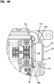
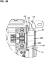
- Figures 49A , 49B , 50 and 51 show the cable seal 36' mounted within the cable seal opening 34.
Landscapes
- Physics & Mathematics (AREA)
- General Physics & Mathematics (AREA)
- Optics & Photonics (AREA)
- Engineering & Computer Science (AREA)
- General Engineering & Computer Science (AREA)
- Mechanical Engineering (AREA)
- Geometry (AREA)
- Light Guides In General And Applications Therefor (AREA)
- Cable Accessories (AREA)
Claims (11)
- Enceinte (20) destinée à être utilisée dans un réseau de distribution à fibres optiques, l'enceinte comprenant :un boîtier (22) définissant un intérieur de boîtier (28) et une ouverture de presse-étoupe (34) ;un presse-étoupe (36, 36') monté au sein de l'ouverture de presse-étoupe, le presse-étoupe définissant un port de câble majeur (44) ;une station d'ancrage de câble (38) positionnée au sein du boîtier pour ancrer un câble par rapport au boîtier, la station d'ancrage de câble comprenant un emplacement de serrage de câble (40) en alignement avec l'ouverture de presse-étoupe ;une fiche réductrice de taille de port monobloc (42a, 42b) définissant un port de câble mineur (46a, 46b) qui s'étend sur une longueur de la fiche réductrice de taille de port, la fiche réductrice de taille de port ayant des première et deuxième portions (80a, 80b, 82a, 82b) positionnées le long de la longueur de la fiche réductrice de taille de port, la fiche réductrice de taille de port (42a, 42b) étant dimensionnée et façonnée de telle sorte que la première portion (80a, 80b) de la fiche réductrice de taille de port (42a, 42b) est configurée pour s'ajuster au sein du port de câble majeur et la deuxième portion (82a, 82b) de la fiche réductrice de taille de port (42a, 42b)
est configurée pour s'ajuster au sein de l'emplacement de serrage ; etune fiche borgne monobloc (48a, 48b) qui s'ajuste au sein du port de câble mineur (46a, 46b), la fiche borgne ayant une première étendue
(102a, 102b) qui coïncide avec la première portion de la fiche réductrice de taille de port et une deuxième étendue(104a, 104b) qui coïncide avec la deuxième portion de la fiche réductrice de taille de port, la première étendue(102a, 102b) remplissant le port de câble mineur (46a, 46b) au niveau de la première portion (80a, 80b) de la fiche réductrice de taille de port pour sceller le port de câble mineur (46a, 46b) lorsque le port de câble mineur (46a, 46b) n'est pas utilisé, la deuxième étendue (104a, 104b) remplissant le port de câble mineur (46a, 46b) au niveau de la deuxième portion (82a, 82b) de la fiche réductrice de taille de port pour limiter l'espace vide au sein de la deuxième portion (82a, 82b) de telle sorte que la deuxième portion (82a, 82b) ne se déforme pas de manière excessive au sein de l'emplacement de serrage de la station d'ancrage de câble (38),caractérisée en ce quele port de câble mineur (46a, 46b) a une forme en coupe transversale qui est complètement ceinte au niveau de la première portion (80a, 80b) de la fiche réductrice de taille de port (46a, 46b) et qui a un côté ouvert au niveau de la deuxième portion (80a, 80b) de la fiche réductrice de taille de port (46a, 46b). - Enceinte selon la revendication 1, dans laquelle la première portion de la fiche réductrice de taille de port a une forme tronconique ayant une extrémité majeure et une extrémité mineure, et la deuxième portion de la fiche réductrice de taille de port a une forme cylindrique et est positionnée de manière adjacente à l'extrémité mineure de la forme tronconique.
- Enceinte selon la revendication 2, dans laquelle la fiche réductrice de taille de port comprend des épaulements de retenue positionnés de manière adjacente aux extrémités majeure et mineure de la forme tronconique.
- Enceinte selon la revendication 2, dans laquelle le port de câble majeur a une forme tronconique qui concorde avec la forme tronconique de la première portion de la fiche réductrice de taille de port.
- Enceinte selon la revendication 1, dans laquelle le boîtier comprend des première et deuxième pièces de boîtier (24, 26) configurées pour être couplées ensemble pour définir l'intérieur de boîtier, les première et deuxième pièces de boîtier se connectant au niveau d'un emplacement de connexion (30) qui s'étend autour d'un périmètre (P) du boîtier, l'enceinte comprenant également un joint (32) pour fournir un scellement périphérique entre la première pièce de boîtier et la deuxième pièce de boîtier, le joint étant positionné entre les première et deuxième pièces de boîtier au niveau de l'emplacement de connexion.
- Enceinte selon la revendication 5, dans laquelle le joint a une forme en coupe transversale comprenant une bande ayant une longueur qui s'étend entre les première et deuxième extrémités, dans laquelle la bande comprend des premier et deuxième côtés qui s'étendent le long de la longueur entre les première et deuxième extrémités, dans laquelle la forme en coupe transversale a des têtes élargies au niveau des première et deuxième extrémités, dans laquelle la forme en coupe transversale a l'au moins une première nervure qui fait saillie vers l'extérieur depuis le premier côté de la bande au niveau d'un emplacement entre les têtes élargies, dans laquelle la forme en coupe transversale a l'au moins une deuxième nervure qui fait saillie vers l'extérieur depuis le deuxième côté de la bande au niveau d'un emplacement entre les têtes élargies, et dans laquelle le joint est comprimé entre les première et deuxième pièces de boîtier dans une orientation de compression parallèle à la longueur de la bande de sorte que la bande est comprimée axialement le long de sa longueur.
- Enceinte selon la revendication 6, dans laquelle la forme en coupe transversale du joint est symétrique autour d'un axe qui est parallèle à la longueur de la bande et qui coupe la bande en deux parties égales.
- Enceinte selon la revendication 6, dans laquelle la première nervure est l'une d'une pluralité de premières nervures qui font saillie vers l'extérieur depuis le premier côté de la bande, et dans laquelle la deuxième nervure est l'une d'une pluralité de deuxièmes nervures qui font saillie vers l'extérieur depuis le deuxième côté de la bande.
- Enceinte selon la revendication 8, dans laquelle les premières nervures sont espacées le long de la longueur de la bande et sont parallèles les unes par rapport aux autres, et dans laquelle les deuxièmes nervures sont espacées les unes des autres le long de la longueur de la bande et sont parallèles les unes par rapport aux autres.
- Enceinte selon la revendication 5, dans laquelle le presse-étoupe comprend une surface périphérique positionnée au niveau de l'emplacement de connexion, dans laquelle les première et deuxième pièces de boîtier définissent respectivement des première et deuxième surfaces de mise en prise de joint opposées au niveau de l'emplacement de connexion, dans laquelle le joint est comprimé entre les première et deuxième surfaces de mise en prise de joint opposées, dans laquelle la première surface de mise en prise de joint a des bords définissant un espace qui définissent un espace dans la première surface de mise en prise de joint au niveau de l'ouverture de presse-étoupe, dans laquelle la surface périphérique du presse-étoupe établit un pont entre l'espace et les bords définissant un espace de la première surface de mise en prise de joint, dans laquelle le joint s'étend d'un bout à l'autre de la surface périphérique et d'un bout à l'autre des bords définissant un espace de la première surface de mise en prise de joint, dans laquelle le presse-étoupe comprend un corps principal et des languettes d'étanchéité qui font saillie vers l'extérieur à partir du corps principal, et dans laquelle les languettes d'étanchéité s'étendent d'un bout à l'autre des bords définissant un espace et sont positionnées entre le joint et la première surface de mise en prise de joint.
- Enceinte selon la revendication 5, dans laquelle le presse-étoupe comprend une surface périphérique positionnée au niveau de l'emplacement de connexion, dans laquelle les première et deuxième pièces de boîtier définissent respectivement des première et deuxième surfaces de mise en prise de joint opposées au niveau de l'emplacement de connexion, dans laquelle le joint est comprimé entre les première et deuxième surfaces de mise en prise de joint opposées, dans laquelle la première surface de mise en prise de joint a des bords définissant un espace qui définissent un espace dans la première surface de mise en prise de joint au niveau de l'ouverture de presse-étoupe, dans laquelle la surface périphérique du presse-étoupe établit un pont entre l'espace et les bords définissant un espace de la première surface de mise en prise de joint, dans laquelle le joint s'étend d'un bout à l'autre de la surface périphérique et d'un bout à l'autre des bords définissant un espace de la première surface de mise en prise de joint, et dans laquelle la surface périphérique du presse-étoupe comprend une portion intermédiaire qui est surélevée par rapport à la première surface de mise en prise de joint et comprend également des portions de chanfrein extérieures sur des côtés opposés de la portion intermédiaire qui s'incline vers le bas depuis la portion intermédiaire vers les bords définissant un espace de la première surface de mise en prise de joint.
Applications Claiming Priority (3)
| Application Number | Priority Date | Filing Date | Title |
|---|---|---|---|
| US201462074967P | 2014-11-04 | 2014-11-04 | |
| PCT/EP2015/075694 WO2016071394A2 (fr) | 2014-11-04 | 2015-11-04 | Boîtier destiné à être utilisé dans un réseau de distribution à fibres optiques |
| EP15788438.8A EP3215882B1 (fr) | 2014-11-04 | 2015-11-04 | Boîtier destiné à être utilisé dans un réseau de distribution à fibres optiques |
Related Parent Applications (1)
| Application Number | Title | Priority Date | Filing Date |
|---|---|---|---|
| EP15788438.8A Division EP3215882B1 (fr) | 2014-11-04 | 2015-11-04 | Boîtier destiné à être utilisé dans un réseau de distribution à fibres optiques |
Publications (2)
| Publication Number | Publication Date |
|---|---|
| EP3674764A1 EP3674764A1 (fr) | 2020-07-01 |
| EP3674764B1 true EP3674764B1 (fr) | 2025-06-18 |
Family
ID=54366234
Family Applications (2)
| Application Number | Title | Priority Date | Filing Date |
|---|---|---|---|
| EP15788438.8A Active EP3215882B1 (fr) | 2014-11-04 | 2015-11-04 | Boîtier destiné à être utilisé dans un réseau de distribution à fibres optiques |
| EP20151309.0A Active EP3674764B1 (fr) | 2014-11-04 | 2015-11-04 | Boîtier destiné à être utilisé dans un réseau de distribution à fibres optiques |
Family Applications Before (1)
| Application Number | Title | Priority Date | Filing Date |
|---|---|---|---|
| EP15788438.8A Active EP3215882B1 (fr) | 2014-11-04 | 2015-11-04 | Boîtier destiné à être utilisé dans un réseau de distribution à fibres optiques |
Country Status (5)
| Country | Link |
|---|---|
| US (4) | US10288829B2 (fr) |
| EP (2) | EP3215882B1 (fr) |
| ES (2) | ES2774794T3 (fr) |
| PL (1) | PL3215882T3 (fr) |
| WO (1) | WO2016071394A2 (fr) |
Families Citing this family (14)
| Publication number | Priority date | Publication date | Assignee | Title |
|---|---|---|---|---|
| PL2759860T3 (pl) * | 2009-09-28 | 2018-07-31 | Te Connectivity Nederland B.V. | Obudowa uszczelniająca dla złącza na kablu, takiego jak standardowe złącze światłowodowe |
| US10288829B2 (en) * | 2014-11-04 | 2019-05-14 | CommScope Connectivity Belgium BVBA | Enclosure for use in a fiber optic distribution network |
| CN112180529B (zh) | 2016-05-23 | 2023-03-10 | 康普连通比利时私人有限公司 | 带有加固的自支撑系绳的光学终端封装件 |
| WO2020061283A1 (fr) * | 2018-09-21 | 2020-03-26 | Commscope Technologies Llc | Dispositif d'étanchéité de câble à fibre optique |
| US11109497B2 (en) * | 2018-10-17 | 2021-08-31 | Arris Enterprises Llc | Backward-compatible extended size node lid to provide additional real estate for future functionality |
| WO2020097189A2 (fr) | 2018-11-09 | 2020-05-14 | Corning Research & Development Corporation | Réseaux de fibres optiques et terminaux à fibres optiques présentant une connectivité sans fil |
| US12095244B2 (en) | 2019-09-24 | 2024-09-17 | Commscope Technologies Llc | Composite cable seal |
| US12124098B2 (en) | 2019-11-11 | 2024-10-22 | Commscope Technologies Llc | Cable sealing arrangement for an enclosure |
| WO2021104603A1 (fr) * | 2019-11-25 | 2021-06-03 | Abb Schweiz Ag | Enceinte pour dispositif électrique et procédé d'obturation d'une ouverture traversante d'une enceinte |
| US11635577B2 (en) * | 2020-01-08 | 2023-04-25 | Clearfield, Inc. | Gasket for a sealed optical fiber terminal |
| US12230948B2 (en) * | 2020-01-31 | 2025-02-18 | CommScope Connectivity Belgium BVBA | Cable sealing unit with multiple configurations |
| US11460655B2 (en) * | 2020-02-16 | 2022-10-04 | Corning Research & Development Corporation | Cable entry sealing systems for telecommunication enclosures |
| US20250020883A1 (en) * | 2023-07-10 | 2025-01-16 | Sterlite Technologies Limited | High-Density Fiber Enclosure |
| WO2025230765A1 (fr) * | 2024-04-30 | 2025-11-06 | Outdoor Wireless Networks LLC | Ensembles système de gestion de câble d'alimentation |
Citations (5)
| Publication number | Priority date | Publication date | Assignee | Title |
|---|---|---|---|---|
| DE1815906U (de) * | 1960-03-19 | 1960-08-04 | Bettermann Elektro O H G | Abgedichtetes gehaeuse mit wasserdichter leitungseinfuehrung fuer elektrische installationsgeraete. |
| US5313546A (en) * | 1991-11-29 | 1994-05-17 | Sirti, S.P.A. | Hermetically sealed joint cover for fibre optic cables |
| FR2917183A1 (fr) * | 2007-06-07 | 2008-12-12 | Free Soc Par Actions Simplifie | Boitier de raccordement pour fibres optiques muni de moyens d'etancheite. |
| DE102008032572A1 (de) * | 2008-07-11 | 2010-02-04 | Dichtungstechnik G. Bruss Gmbh & Co. Kg | Dichtelement aus einem Elastomerwerkstoff zur statischen Abdichtung eines Gehäuseteils |
| WO2014128137A2 (fr) * | 2013-02-19 | 2014-08-28 | Tyco Electronics Raychem Bvba | Interface de scellement pour un boîtier de télécommunications |
Family Cites Families (45)
| Publication number | Priority date | Publication date | Assignee | Title |
|---|---|---|---|---|
| NO133599L (fr) * | 1967-09-20 | |||
| JP2568578Y2 (ja) * | 1992-01-31 | 1998-04-15 | 住友電装株式会社 | 防水コネクタ用ゴム部品 |
| JP2946450B2 (ja) | 1993-04-27 | 1999-09-06 | コマツ電子金属株式会社 | 半導体ウェーハ包装容器 |
| US5442140A (en) * | 1993-10-05 | 1995-08-15 | Homac Mfg. Company | Conduit and cable sealer |
| DE59703529D1 (de) | 1996-03-20 | 2001-06-21 | Rxs Ges Fuer Vermoegensverwalt | Kabelmuffe |
| JP3247048B2 (ja) * | 1996-08-28 | 2002-01-15 | 矢崎総業株式会社 | リップ付きゴム製品 |
| JP2852281B2 (ja) | 1996-11-22 | 1999-01-27 | 住友電気工業株式会社 | 光ケーブル収納ケースの通信機器筐体への取り付け部 |
| FR2758400B1 (fr) * | 1997-01-15 | 1999-02-19 | Telecommunications Sa | Dispositif de raccordement de cables a fibres optiques |
| US6003878A (en) * | 1997-10-06 | 1999-12-21 | Freudenberg-Nok General Partnership | T-joint gasket assembly |
| JPH11126648A (ja) * | 1997-10-21 | 1999-05-11 | Yazaki Corp | パッキンの保持構造 |
| FR2775845B1 (fr) * | 1998-03-09 | 2000-04-14 | Alsthom Cge Alcatel | Boitier etanche d'appareillage a acces pour cable |
| US6218620B1 (en) * | 1999-05-19 | 2001-04-17 | John M. Michel | Housing for telephone splices and the like and method |
| US7113679B2 (en) | 2000-05-26 | 2006-09-26 | Corning Cable Systems, Llc | Fiber optic drop cables and preconnectorized assemblies having toning portions |
| US6648520B2 (en) | 2001-09-28 | 2003-11-18 | Corning Cable Systems Llc | Fiber optic plug |
| CN100417847C (zh) * | 2002-11-12 | 2008-09-10 | Nok株式会社 | 橡胶状弹性部件 |
| US7239789B2 (en) * | 2003-10-06 | 2007-07-03 | Preformed Line Products Company | Optical fiber splice case |
| US7013074B2 (en) | 2004-02-06 | 2006-03-14 | Corning Cable Systems Llc | Optical connection closure having at least one connector port |
| US7442884B2 (en) * | 2004-08-30 | 2008-10-28 | 3M Innovative Properties Company | Sealing member for enclosures |
| US7264402B2 (en) | 2005-03-10 | 2007-09-04 | Corning Cable Systems Llc | Multi-fiber optic receptacle and plug assembly |
| US20060220326A1 (en) * | 2005-03-30 | 2006-10-05 | Andrew Corporation | Multilobe gasket and sealing groove |
| US7186929B2 (en) | 2005-07-08 | 2007-03-06 | 3M Innovative Properties Company | Sealing member for an entry port |
| US7568943B2 (en) * | 2005-07-27 | 2009-08-04 | Corning Cable Systems Llc | Sealing and retaining cable attachment for telecommunications closures |
| JP5151241B2 (ja) * | 2007-05-10 | 2013-02-27 | Nok株式会社 | 密封構造 |
| US20090159332A1 (en) * | 2007-10-26 | 2009-06-25 | Matthew Holmberg | Cable seal assembly |
| US7751675B2 (en) | 2007-12-11 | 2010-07-06 | Adc Telecommunications, Inc. | Wall box adapted to be mounted at a mid-span access location of a telecommunications cable |
| US7744286B2 (en) | 2007-12-11 | 2010-06-29 | Adc Telecommunications, Inc. | Hardened fiber optic connection system with multiple configurations |
| EP2238493A2 (fr) | 2008-01-09 | 2010-10-13 | ADC Telecommunications, Inc. | Coffret mural conçu pour être monté en un emplacement d'accès à mi-portée d'un câble de télécommunications |
| US8718434B2 (en) | 2008-07-01 | 2014-05-06 | Adc Telecommunications, Inc. | Cable enclosure with sealed cable entry port |
| CA2688677C (fr) * | 2008-12-15 | 2018-10-02 | Randy Soibel | Contenant avec garniture d'etancheite souple |
| US8081857B2 (en) * | 2008-12-31 | 2011-12-20 | Opterna Am, Inc. | System for an internal rotating storage spool combined with top and bottom cable access in a fiber distribution terminal |
| EP2391917A1 (fr) | 2009-01-28 | 2011-12-07 | ADC Telecommunications, Inc. | Boîtier pour fibres optiques |
| PL2759860T3 (pl) | 2009-09-28 | 2018-07-31 | Te Connectivity Nederland B.V. | Obudowa uszczelniająca dla złącza na kablu, takiego jak standardowe złącze światłowodowe |
| US8820798B2 (en) * | 2010-03-29 | 2014-09-02 | Delphi International Operations Luxembourg S.A.R.L. | Interfacial seal with a groove |
| WO2012074688A2 (fr) | 2010-12-01 | 2012-06-07 | 3M Innovative Properties Company | Organiseur et boîtier de distribution de fibres |
| US8903216B2 (en) | 2011-03-07 | 2014-12-02 | Tyco Electronics Corporation | Cable strain relief clamping devices and methods for using the same |
| US9520310B2 (en) * | 2012-05-04 | 2016-12-13 | Entegris, Inc. | Wafer container with door interface seal |
| BR112014027393A2 (pt) * | 2012-05-04 | 2017-06-27 | Tyco Electronics Corp | sistema de ancoragem de cabo para um invólucro de fibra óptica |
| WO2014005917A2 (fr) * | 2012-07-02 | 2014-01-09 | Tyco Electronics Raychem Bvba | Enceinte réouvrable |
| MX342790B (es) | 2012-07-02 | 2016-10-12 | Tyco Electronics Raychem Bvba | Unidad de sellado de cable con módulos de sellado múltiple. |
| WO2014127088A1 (fr) * | 2013-02-14 | 2014-08-21 | Tyco Electronics Corporation | Obturateur d'orifice à engagement automatique |
| CN105659136A (zh) | 2013-08-24 | 2016-06-08 | 泰科电子瑞侃有限公司 | 用于光缆外壳的密封结构 |
| EP3132298B1 (fr) | 2014-04-14 | 2021-08-11 | CommScope Connectivity Belgium BVBA | Boîtier pour fibres optiques à tiroir de gestion de câbles |
| US10288829B2 (en) * | 2014-11-04 | 2019-05-14 | CommScope Connectivity Belgium BVBA | Enclosure for use in a fiber optic distribution network |
| ES1134583Y (es) | 2014-11-19 | 2015-03-05 | Telefonica Sa | Caja terminal óptica exterior |
| US9575279B1 (en) * | 2016-04-14 | 2017-02-21 | Furukawa Industrial S.A. Produtos Elétricos | Optic termination box |
-
2015
- 2015-11-04 US US15/524,431 patent/US10288829B2/en active Active
- 2015-11-04 ES ES15788438T patent/ES2774794T3/es active Active
- 2015-11-04 EP EP15788438.8A patent/EP3215882B1/fr active Active
- 2015-11-04 PL PL15788438T patent/PL3215882T3/pl unknown
- 2015-11-04 ES ES20151309T patent/ES3037493T3/es active Active
- 2015-11-04 EP EP20151309.0A patent/EP3674764B1/fr active Active
- 2015-11-04 WO PCT/EP2015/075694 patent/WO2016071394A2/fr not_active Ceased
-
2019
- 2019-03-29 US US16/370,293 patent/US10606008B2/en active Active
-
2020
- 2020-02-20 US US16/796,307 patent/US11099343B2/en active Active
-
2021
- 2021-07-20 US US17/380,446 patent/US11460656B2/en active Active
Patent Citations (5)
| Publication number | Priority date | Publication date | Assignee | Title |
|---|---|---|---|---|
| DE1815906U (de) * | 1960-03-19 | 1960-08-04 | Bettermann Elektro O H G | Abgedichtetes gehaeuse mit wasserdichter leitungseinfuehrung fuer elektrische installationsgeraete. |
| US5313546A (en) * | 1991-11-29 | 1994-05-17 | Sirti, S.P.A. | Hermetically sealed joint cover for fibre optic cables |
| FR2917183A1 (fr) * | 2007-06-07 | 2008-12-12 | Free Soc Par Actions Simplifie | Boitier de raccordement pour fibres optiques muni de moyens d'etancheite. |
| DE102008032572A1 (de) * | 2008-07-11 | 2010-02-04 | Dichtungstechnik G. Bruss Gmbh & Co. Kg | Dichtelement aus einem Elastomerwerkstoff zur statischen Abdichtung eines Gehäuseteils |
| WO2014128137A2 (fr) * | 2013-02-19 | 2014-08-28 | Tyco Electronics Raychem Bvba | Interface de scellement pour un boîtier de télécommunications |
Also Published As
| Publication number | Publication date |
|---|---|
| EP3215882A2 (fr) | 2017-09-13 |
| EP3215882B1 (fr) | 2020-01-15 |
| US20190227249A1 (en) | 2019-07-25 |
| WO2016071394A3 (fr) | 2016-06-30 |
| US10288829B2 (en) | 2019-05-14 |
| US20200192044A1 (en) | 2020-06-18 |
| WO2016071394A2 (fr) | 2016-05-12 |
| US11460656B2 (en) | 2022-10-04 |
| EP3674764A1 (fr) | 2020-07-01 |
| US11099343B2 (en) | 2021-08-24 |
| ES2774794T3 (es) | 2020-07-22 |
| PL3215882T3 (pl) | 2020-07-13 |
| US20180284376A1 (en) | 2018-10-04 |
| US10606008B2 (en) | 2020-03-31 |
| ES3037493T3 (en) | 2025-10-02 |
| US20210349275A1 (en) | 2021-11-11 |
Similar Documents
| Publication | Publication Date | Title |
|---|---|---|
| US11460656B2 (en) | Enclosure for use in a fiber optic distribution network | |
| US20210041652A1 (en) | Fiber optic closure | |
| EP3132298B1 (fr) | Boîtier pour fibres optiques à tiroir de gestion de câbles | |
| EP3311210B1 (fr) | Boîtier de terminaison optique | |
| US7428366B2 (en) | Optical fiber termination apparatus with connector adaptor and method for using the same | |
| US9696511B2 (en) | Sealing structures for optical cable closure | |
| US10007080B2 (en) | Flex port enabled telecommunications closure | |
| US20250306321A1 (en) | Splice enclosure with connectorized patching functionality | |
| WO2014035611A1 (fr) | Plateau d'épissure de fibres optiques fermé de façon étanche | |
| US10054741B2 (en) | Fiber optic enclosure assembly | |
| US20240385404A1 (en) | Sealing arrangement for a cable entrance to an enclosure |
Legal Events
| Date | Code | Title | Description |
|---|---|---|---|
| PUAI | Public reference made under article 153(3) epc to a published international application that has entered the european phase |
Free format text: ORIGINAL CODE: 0009012 |
|
| STAA | Information on the status of an ep patent application or granted ep patent |
Free format text: STATUS: THE APPLICATION HAS BEEN PUBLISHED |
|
| AC | Divisional application: reference to earlier application |
Ref document number: 3215882 Country of ref document: EP Kind code of ref document: P |
|
| AK | Designated contracting states |
Kind code of ref document: A1 Designated state(s): AL AT BE BG CH CY CZ DE DK EE ES FI FR GB GR HR HU IE IS IT LI LT LU LV MC MK MT NL NO PL PT RO RS SE SI SK SM TR |
|
| STAA | Information on the status of an ep patent application or granted ep patent |
Free format text: STATUS: REQUEST FOR EXAMINATION WAS MADE |
|
| 17P | Request for examination filed |
Effective date: 20210104 |
|
| RBV | Designated contracting states (corrected) |
Designated state(s): AL AT BE BG CH CY CZ DE DK EE ES FI FR GB GR HR HU IE IS IT LI LT LU LV MC MK MT NL NO PL PT RO RS SE SI SK SM TR |
|
| STAA | Information on the status of an ep patent application or granted ep patent |
Free format text: STATUS: EXAMINATION IS IN PROGRESS |
|
| 17Q | First examination report despatched |
Effective date: 20221104 |
|
| GRAP | Despatch of communication of intention to grant a patent |
Free format text: ORIGINAL CODE: EPIDOSNIGR1 |
|
| STAA | Information on the status of an ep patent application or granted ep patent |
Free format text: STATUS: GRANT OF PATENT IS INTENDED |
|
| INTG | Intention to grant announced |
Effective date: 20250110 |
|
| GRAS | Grant fee paid |
Free format text: ORIGINAL CODE: EPIDOSNIGR3 |
|
| GRAA | (expected) grant |
Free format text: ORIGINAL CODE: 0009210 |
|
| STAA | Information on the status of an ep patent application or granted ep patent |
Free format text: STATUS: THE PATENT HAS BEEN GRANTED |
|
| AC | Divisional application: reference to earlier application |
Ref document number: 3215882 Country of ref document: EP Kind code of ref document: P |
|
| AK | Designated contracting states |
Kind code of ref document: B1 Designated state(s): AL AT BE BG CH CY CZ DE DK EE ES FI FR GB GR HR HU IE IS IT LI LT LU LV MC MK MT NL NO PL PT RO RS SE SI SK SM TR |
|
| REG | Reference to a national code |
Ref country code: GB Ref legal event code: FG4D |
|
| REG | Reference to a national code |
Ref country code: CH Ref legal event code: EP |
|
| REG | Reference to a national code |
Ref country code: DE Ref legal event code: R096 Ref document number: 602015091862 Country of ref document: DE |
|
| REG | Reference to a national code |
Ref country code: CH Ref legal event code: EP |
|
| REG | Reference to a national code |
Ref country code: IE Ref legal event code: FG4D |
|
| REG | Reference to a national code |
Ref country code: ES Ref legal event code: FG2A Ref document number: 3037493 Country of ref document: ES Kind code of ref document: T3 Effective date: 20251002 |
|
| PG25 | Lapsed in a contracting state [announced via postgrant information from national office to epo] |
Ref country code: FI Free format text: LAPSE BECAUSE OF FAILURE TO SUBMIT A TRANSLATION OF THE DESCRIPTION OR TO PAY THE FEE WITHIN THE PRESCRIBED TIME-LIMIT Effective date: 20250618 |
|
| REG | Reference to a national code |
Ref country code: LT Ref legal event code: MG9D |
|
| PG25 | Lapsed in a contracting state [announced via postgrant information from national office to epo] |
Ref country code: GR Free format text: LAPSE BECAUSE OF FAILURE TO SUBMIT A TRANSLATION OF THE DESCRIPTION OR TO PAY THE FEE WITHIN THE PRESCRIBED TIME-LIMIT Effective date: 20250919 Ref country code: NO Free format text: LAPSE BECAUSE OF FAILURE TO SUBMIT A TRANSLATION OF THE DESCRIPTION OR TO PAY THE FEE WITHIN THE PRESCRIBED TIME-LIMIT Effective date: 20250918 |
|
| PG25 | Lapsed in a contracting state [announced via postgrant information from national office to epo] |
Ref country code: BG Free format text: LAPSE BECAUSE OF FAILURE TO SUBMIT A TRANSLATION OF THE DESCRIPTION OR TO PAY THE FEE WITHIN THE PRESCRIBED TIME-LIMIT Effective date: 20250618 |
|
| PG25 | Lapsed in a contracting state [announced via postgrant information from national office to epo] |
Ref country code: HR Free format text: LAPSE BECAUSE OF FAILURE TO SUBMIT A TRANSLATION OF THE DESCRIPTION OR TO PAY THE FEE WITHIN THE PRESCRIBED TIME-LIMIT Effective date: 20250618 |
|
| PG25 | Lapsed in a contracting state [announced via postgrant information from national office to epo] |
Ref country code: RS Free format text: LAPSE BECAUSE OF FAILURE TO SUBMIT A TRANSLATION OF THE DESCRIPTION OR TO PAY THE FEE WITHIN THE PRESCRIBED TIME-LIMIT Effective date: 20250918 |
|
| REG | Reference to a national code |
Ref country code: NL Ref legal event code: MP Effective date: 20250618 |
|
| PG25 | Lapsed in a contracting state [announced via postgrant information from national office to epo] |
Ref country code: LV Free format text: LAPSE BECAUSE OF FAILURE TO SUBMIT A TRANSLATION OF THE DESCRIPTION OR TO PAY THE FEE WITHIN THE PRESCRIBED TIME-LIMIT Effective date: 20250618 |
|
| PG25 | Lapsed in a contracting state [announced via postgrant information from national office to epo] |
Ref country code: NL Free format text: LAPSE BECAUSE OF FAILURE TO SUBMIT A TRANSLATION OF THE DESCRIPTION OR TO PAY THE FEE WITHIN THE PRESCRIBED TIME-LIMIT Effective date: 20250618 |
|
| PG25 | Lapsed in a contracting state [announced via postgrant information from national office to epo] |
Ref country code: PT Free format text: LAPSE BECAUSE OF FAILURE TO SUBMIT A TRANSLATION OF THE DESCRIPTION OR TO PAY THE FEE WITHIN THE PRESCRIBED TIME-LIMIT Effective date: 20251020 |
|
| REG | Reference to a national code |
Ref country code: AT Ref legal event code: MK05 Ref document number: 1804700 Country of ref document: AT Kind code of ref document: T Effective date: 20250618 |
|
| PG25 | Lapsed in a contracting state [announced via postgrant information from national office to epo] |
Ref country code: IS Free format text: LAPSE BECAUSE OF FAILURE TO SUBMIT A TRANSLATION OF THE DESCRIPTION OR TO PAY THE FEE WITHIN THE PRESCRIBED TIME-LIMIT Effective date: 20251018 |
|
| PGFP | Annual fee paid to national office [announced via postgrant information from national office to epo] |
Ref country code: GB Payment date: 20251127 Year of fee payment: 11 |
|
| PG25 | Lapsed in a contracting state [announced via postgrant information from national office to epo] |
Ref country code: SM Free format text: LAPSE BECAUSE OF FAILURE TO SUBMIT A TRANSLATION OF THE DESCRIPTION OR TO PAY THE FEE WITHIN THE PRESCRIBED TIME-LIMIT Effective date: 20250618 Ref country code: AT Free format text: LAPSE BECAUSE OF FAILURE TO SUBMIT A TRANSLATION OF THE DESCRIPTION OR TO PAY THE FEE WITHIN THE PRESCRIBED TIME-LIMIT Effective date: 20250618 |
|
| PG25 | Lapsed in a contracting state [announced via postgrant information from national office to epo] |
Ref country code: CZ Free format text: LAPSE BECAUSE OF FAILURE TO SUBMIT A TRANSLATION OF THE DESCRIPTION OR TO PAY THE FEE WITHIN THE PRESCRIBED TIME-LIMIT Effective date: 20250618 |
|
| PG25 | Lapsed in a contracting state [announced via postgrant information from national office to epo] |
Ref country code: PL Free format text: LAPSE BECAUSE OF FAILURE TO SUBMIT A TRANSLATION OF THE DESCRIPTION OR TO PAY THE FEE WITHIN THE PRESCRIBED TIME-LIMIT Effective date: 20250618 |
|
| PG25 | Lapsed in a contracting state [announced via postgrant information from national office to epo] |
Ref country code: EE Free format text: LAPSE BECAUSE OF FAILURE TO SUBMIT A TRANSLATION OF THE DESCRIPTION OR TO PAY THE FEE WITHIN THE PRESCRIBED TIME-LIMIT Effective date: 20250618 |
|
| PG25 | Lapsed in a contracting state [announced via postgrant information from national office to epo] |
Ref country code: SK Free format text: LAPSE BECAUSE OF FAILURE TO SUBMIT A TRANSLATION OF THE DESCRIPTION OR TO PAY THE FEE WITHIN THE PRESCRIBED TIME-LIMIT Effective date: 20250618 Ref country code: RO Free format text: LAPSE BECAUSE OF FAILURE TO SUBMIT A TRANSLATION OF THE DESCRIPTION OR TO PAY THE FEE WITHIN THE PRESCRIBED TIME-LIMIT Effective date: 20250618 |
|
| PGFP | Annual fee paid to national office [announced via postgrant information from national office to epo] |
Ref country code: ES Payment date: 20251201 Year of fee payment: 11 |
|
| PG25 | Lapsed in a contracting state [announced via postgrant information from national office to epo] |
Ref country code: DK Free format text: LAPSE BECAUSE OF FAILURE TO SUBMIT A TRANSLATION OF THE DESCRIPTION OR TO PAY THE FEE WITHIN THE PRESCRIBED TIME-LIMIT Effective date: 20250618 |
|
| PG25 | Lapsed in a contracting state [announced via postgrant information from national office to epo] |
Ref country code: IT Free format text: LAPSE BECAUSE OF FAILURE TO SUBMIT A TRANSLATION OF THE DESCRIPTION OR TO PAY THE FEE WITHIN THE PRESCRIBED TIME-LIMIT Effective date: 20250618 |
|
| PLBE | No opposition filed within time limit |
Free format text: ORIGINAL CODE: 0009261 |
|
| STAA | Information on the status of an ep patent application or granted ep patent |
Free format text: STATUS: NO OPPOSITION FILED WITHIN TIME LIMIT |