EP3674830A1 - Server und verfahren zur steuerung der laserbestrahlung der bewegungsbahn eines roboters und roboter, der sich darauf basierend bewegt - Google Patents
Server und verfahren zur steuerung der laserbestrahlung der bewegungsbahn eines roboters und roboter, der sich darauf basierend bewegt Download PDFInfo
- Publication number
- EP3674830A1 EP3674830A1 EP19210919.7A EP19210919A EP3674830A1 EP 3674830 A1 EP3674830 A1 EP 3674830A1 EP 19210919 A EP19210919 A EP 19210919A EP 3674830 A1 EP3674830 A1 EP 3674830A1
- Authority
- EP
- European Patent Office
- Prior art keywords
- robot
- laser
- laser irradiation
- main server
- information
- Prior art date
- Legal status (The legal status is an assumption and is not a legal conclusion. Google has not performed a legal analysis and makes no representation as to the accuracy of the status listed.)
- Granted
Links
Images




Classifications
-
- G—PHYSICS
- G05—CONTROLLING; REGULATING
- G05D—SYSTEMS FOR CONTROLLING OR REGULATING NON-ELECTRIC VARIABLES
- G05D1/00—Control of position, course, altitude or attitude of land, water, air or space vehicles, e.g. using automatic pilots
- G05D1/02—Control of position or course in two dimensions
- G05D1/021—Control of position or course in two dimensions specially adapted to land vehicles
- G05D1/0231—Control of position or course in two dimensions specially adapted to land vehicles using optical position detecting means
- G05D1/0234—Control of position or course in two dimensions specially adapted to land vehicles using optical position detecting means using optical markers or beacons
- G05D1/0236—Control of position or course in two dimensions specially adapted to land vehicles using optical position detecting means using optical markers or beacons in combination with a laser
-
- G—PHYSICS
- G05—CONTROLLING; REGULATING
- G05D—SYSTEMS FOR CONTROLLING OR REGULATING NON-ELECTRIC VARIABLES
- G05D1/00—Control of position, course, altitude or attitude of land, water, air or space vehicles, e.g. using automatic pilots
- G05D1/02—Control of position or course in two dimensions
- G05D1/021—Control of position or course in two dimensions specially adapted to land vehicles
- G05D1/0212—Control of position or course in two dimensions specially adapted to land vehicles with means for defining a desired trajectory
-
- G—PHYSICS
- G05—CONTROLLING; REGULATING
- G05D—SYSTEMS FOR CONTROLLING OR REGULATING NON-ELECTRIC VARIABLES
- G05D1/00—Control of position, course, altitude or attitude of land, water, air or space vehicles, e.g. using automatic pilots
- G05D1/02—Control of position or course in two dimensions
- G05D1/021—Control of position or course in two dimensions specially adapted to land vehicles
- G05D1/0212—Control of position or course in two dimensions specially adapted to land vehicles with means for defining a desired trajectory
- G05D1/0214—Control of position or course in two dimensions specially adapted to land vehicles with means for defining a desired trajectory in accordance with safety or protection criteria, e.g. avoiding hazardous areas
-
- B—PERFORMING OPERATIONS; TRANSPORTING
- B25—HAND TOOLS; PORTABLE POWER-DRIVEN TOOLS; MANIPULATORS
- B25J—MANIPULATORS; CHAMBERS PROVIDED WITH MANIPULATION DEVICES
- B25J9/00—Program-controlled manipulators
- B25J9/16—Program controls
- B25J9/1656—Program controls characterised by programming, planning systems for manipulators
- B25J9/1664—Program controls characterised by programming, planning systems for manipulators characterised by motion, path, trajectory planning
-
- B—PERFORMING OPERATIONS; TRANSPORTING
- B25—HAND TOOLS; PORTABLE POWER-DRIVEN TOOLS; MANIPULATORS
- B25J—MANIPULATORS; CHAMBERS PROVIDED WITH MANIPULATION DEVICES
- B25J9/00—Program-controlled manipulators
- B25J9/16—Program controls
- B25J9/1674—Program controls characterised by safety, monitoring, diagnostic
-
- G—PHYSICS
- G05—CONTROLLING; REGULATING
- G05D—SYSTEMS FOR CONTROLLING OR REGULATING NON-ELECTRIC VARIABLES
- G05D1/00—Control of position, course, altitude or attitude of land, water, air or space vehicles, e.g. using automatic pilots
- G05D1/02—Control of position or course in two dimensions
- G05D1/021—Control of position or course in two dimensions specially adapted to land vehicles
- G05D1/0231—Control of position or course in two dimensions specially adapted to land vehicles using optical position detecting means
-
- G—PHYSICS
- G05—CONTROLLING; REGULATING
- G05D—SYSTEMS FOR CONTROLLING OR REGULATING NON-ELECTRIC VARIABLES
- G05D1/00—Control of position, course, altitude or attitude of land, water, air or space vehicles, e.g. using automatic pilots
- G05D1/02—Control of position or course in two dimensions
- G05D1/021—Control of position or course in two dimensions specially adapted to land vehicles
- G05D1/0231—Control of position or course in two dimensions specially adapted to land vehicles using optical position detecting means
- G05D1/0238—Control of position or course in two dimensions specially adapted to land vehicles using optical position detecting means using obstacle or wall sensors
- G05D1/024—Control of position or course in two dimensions specially adapted to land vehicles using optical position detecting means using obstacle or wall sensors in combination with a laser
-
- G—PHYSICS
- G05—CONTROLLING; REGULATING
- G05D—SYSTEMS FOR CONTROLLING OR REGULATING NON-ELECTRIC VARIABLES
- G05D1/00—Control of position, course, altitude or attitude of land, water, air or space vehicles, e.g. using automatic pilots
- G05D1/02—Control of position or course in two dimensions
- G05D1/021—Control of position or course in two dimensions specially adapted to land vehicles
- G05D1/0231—Control of position or course in two dimensions specially adapted to land vehicles using optical position detecting means
- G05D1/0246—Control of position or course in two dimensions specially adapted to land vehicles using optical position detecting means using a video camera in combination with image processing means
- G05D1/0248—Control of position or course in two dimensions specially adapted to land vehicles using optical position detecting means using a video camera in combination with image processing means in combination with a laser
-
- G—PHYSICS
- G05—CONTROLLING; REGULATING
- G05D—SYSTEMS FOR CONTROLLING OR REGULATING NON-ELECTRIC VARIABLES
- G05D1/00—Control of position, course, altitude or attitude of land, water, air or space vehicles, e.g. using automatic pilots
- G05D1/02—Control of position or course in two dimensions
- G05D1/021—Control of position or course in two dimensions specially adapted to land vehicles
- G05D1/0276—Control of position or course in two dimensions specially adapted to land vehicles using signals provided by a source external to the vehicle
-
- G—PHYSICS
- G05—CONTROLLING; REGULATING
- G05D—SYSTEMS FOR CONTROLLING OR REGULATING NON-ELECTRIC VARIABLES
- G05D1/00—Control of position, course, altitude or attitude of land, water, air or space vehicles, e.g. using automatic pilots
- G05D1/02—Control of position or course in two dimensions
- G05D1/021—Control of position or course in two dimensions specially adapted to land vehicles
- G05D1/0276—Control of position or course in two dimensions specially adapted to land vehicles using signals provided by a source external to the vehicle
- G05D1/028—Control of position or course in two dimensions specially adapted to land vehicles using signals provided by a source external to the vehicle using a RF signal
- G05D1/0282—Control of position or course in two dimensions specially adapted to land vehicles using signals provided by a source external to the vehicle using a RF signal generated in a local control room
Definitions
- the present disclosure relates to a server and a method for controlling laser irradiation of a movement path of a robot, and a robot that moves based thereon.
- a robot may move in various ways.
- the robot may store a map for the entire space and create movement paths on the map.
- the robot may sense an ambient obstacle without any map and generate a path so as to avoid the sensed obstacle.
- This approach requires the robot to form a predetermined path, which means that the robot requires computing power for path generation.
- the robot requires computing power for path generation.
- Conventional technology has a configuration in which a target point of a robot is marked by means of a laser pointer, and the robot moves toward the target point.
- the configuration will be described in more detail with reference to FIG. 1 .
- FIG. 1 illustrates a configuration of irradiating a target point of a robot with a laser pointer according to the related art.
- a laser pointer 16 irradiates (or scans) a laser beam to notify a direction of a robot 12.
- the laser beam mounted on a ceiling indicates a point where the robot should go next, and the robot uses its built-in camera to find the beam and recognizes a direction thereof through image analysis, which suggests a technical configuration to allow the robot to travel by marking the target point with a laser.
- the robot may move along the irradiated laser beam.
- a region in which the laser beam is irradiated is provided as a point, it is necessary to generate a path required to move to the target point, and an obstacle also needs to be sensed by the robot.
- the present disclosure suggests a method for irradiating a high-speed route with respect to travel of a robot, and allowing the robot to recognize and travel the high-speed route.
- the present disclosure is directed to providing a robot capable of receiving a path via a main server without sensing an external obstacle or calculating the path in the process of moving, and moving at a high speed by allowing the path to be marked with a laser.
- the present disclosure is further directed to providing a method and an apparatus for providing a robot with a final result about a path by allowing a main server to generate information about a movement space of the robot and the path.
- a main server configured to control laser irradiation of a movement path of a robot.
- the main server may include a location identifying unit configured to identify a location of a robot in an image photographed by a camera module.
- the main server may include a controller configured to generate a movement path of the robot and control transmission of the movement path to a laser irradiation module capable of outputting the movement path to a vicinity of the robot with a laser.
- the location identifying unit can be included in the controller.
- a robot that moves based on laser irradiation of a movement path.
- the robot may include a laser sensor configured to sense a laser output onto a ground.
- the robot may include a driving unit configured to allow the robot to move, and a controller configured to control the driving unit of the robot according to a laser sensed by the laser sensor to allow the robot to move.
- a method for controlling laser irradiation of a movement path of a robot may include receiving, by a communication unit, an image photographed by a camera module from the camera module or a guiding device including the camera module, identifying, by a location identifying unit, a location of the robot in the image photographed by the camera module, generating, by a controller, a movement path of the robot, selecting, by the controller, a laser irradiation module capable of outputting the movement path to a vicinity of the robot with a laser, and, transmitting, by the communication unit, the movement path to the selected laser irradiation module or to a guiding device including the laser irradiation module.
- features may be described as being performed by separate components for convenience of description. However, these features may be implemented by a single device or module or a feature may be implemented by several devices or modules.
- a robot collectively refers to an apparatus that performs a specific function. Functions performed by the robot include various functions that can be provided by a mobile apparatus, for example, functions of cleaning, crime prevention, guidance, security functions, and the like.
- the robot disclosed herein includes a robot that transports an article, for example, a logistics cart robot or a delivery robot, or a robot that assists a user. That is, the robot according to embodiments of the present disclosure collectively refers to an apparatus that moves, travels or drives while providing a specific function to meet a user's needs.
- FIG. 2 illustrates an example relationship between a main server, and a camera module and a laser irradiation module controlled by the main server.
- a main server 100 may be a computer that performs a sort of server function.
- the main server 100 may estimate a location of a robot.
- the main server 100 may estimate the location of the robot (mobile robot) by analyzing an image acquired by a camera module.
- the main server 100 may generate a path through path planning.
- the main server 100 may perform calculations required for complicated path planning to a destination by using the acquired robot location.
- the main server 100 may output a path obtained as a result of performing calculations to a vicinity of the robot by controlling a laser irradiation module.
- the main server 100 may recalculate the path based on travel of the robot, a change of a surrounding situation, and the like.
- the main server 100 may include a controller 150, a communication unit 180, a location identifying unit 110, and optionally a map storage 120.
- Camera modules 210a and 210b and laser irradiation modules 250a and 250b may be integrally included in guiding each devices 200a and 200b.
- a camera module 210z and a laser irradiation module 250z may be disposed independently.
- the communication unit 180 may communicate with the camera modules 210a, 210b, and 210z and the laser irradiation modules 250a, 250b, and 250z. Alternatively, the communication unit 180 may communicate with the guiding devices 200a and 200b including the two modules. The communication unit 180 may receive an image photographed by the camera modules 210a, 210b, and 210z. The image may include an image of the robot and a mark disposed on the robot to identify a location or direction of the robot.
- the communication unit 180 may receive an image including a mark disposed on the robot from the camera modules 210a and 210b. In addition, the communication unit 180 may transmit detailed information about a laser signal to be output by the laser irradiation module 250a, 250b, and 250z.
- the location identifying unit 110 may identify the location of the robot in the image photographed by the camera modules 210a, 210b, and 210z.
- the location identifying unit 110 may identify absolute location information of the robot based on physical information of the camera modules 210a, 210b, and 210z and relative location information of the robot in the image.
- the location identifying unit 100 can be incorporated to the controller 150. In this situation, the controller 150 may identify the location of the robot.
- the controller 150 may generate a movement path of the robot.
- the controller 150 may control transmission of the movement path to the laser irradiation modules (any one or more of 250a, 250b, ... , 250z) capable of outputting the movement path to the vicinity of the robot with a laser.
- the main server 100 may optionally include a map storage 120 configured to store a location of each robot, a location of the camera module, a location of the laser irradiation module, a location of the obstacle, and the like.
- the location of the obstacle stored in the map storage 120 is a region where the robot cannot move or travel. Therefore, the main server 100 may refer to the location of the obstacle stored in the map storage 120 to identify a region where the robot should avoid in generating a movement path of the robot.
- a system configured to irradiate a path to a robot may consist of three components.
- the system may consist of the main server 100 configured to identify a location of a specific robot and calculate a path so that the robot moves, a camera module 210 configured to photograph a location of the robot or surrounding objects of the robot, and a laser irradiation module 250 that is a path output device configured to scan the route to the vicinity of the robot.
- These components may be configured independently of each other, and may transmit and receive information via a communication function.
- a light irradiation module configured to irradiate light having characteristics such as different wavelengths or different frequencies may be disposed.
- the light irradiation module may be disposed in the guiding device, and a laser sensor of the robot, which will be described later, may also be replaced by a light sensor.
- FIGS. 3 and 4 illustrate a configuration of a guiding device.
- a guiding device 200 may include one camera module 210 and one laser irradiation module 250, as illustrated in FIG. 3 .
- the communication unit 280 may be disposed in the guiding device 200.
- the camera module 210 may be attached to a ceiling or a wall surface, and may figure out a current location of a robot by recognizing a location mark mounted on the robot.
- the laser irradiation module 250 may project a line laser onto a floor surface with respect to a route to be traveled by the robot.
- the communication unit 218 may be disposed in the camera module 210 or the communication unit 218 may be disposed in the laser module 250.
- the other module may use the communication unit 218.
- the laser irradiation module 250 may communicate with the main server 100 via the camera module 210.
- the communication unit 258 is disposed only in the laser irradiation module 250
- the camera module 210 may communicate with the main server 100 via the laser irradiation module 250.
- one guiding device 200 may include m camera modules 210 and n laser irradiation modules 250 (where m and n may be one or more natural numbers).
- the camera module 210 may include an image acquisition unit 212 configured to photograph an image and a view angle adjusting unit 214 for accuracy of image acquisition.
- the camera module 210 may transmit information about which direction and at what magnification the image is photographed together with the image.
- the laser irradiation module 250 may include a laser output unit 252 configured to output a laser and an output pattern storage unit 254.
- the laser output unit 252 may output a laser in a specific manner according to instructions of the main server 100.
- the output pattern storage unit 254 may store a pattern such as a shape, color, frequency, or the like of a laser to be output. This implementation may allow the robot to move according to a laser output of a pattern assigned to itself by outputting a laser in a different pattern for each robot even when routes are arranged adjacent to each other.
- the laser irradiation module 250 may further include an obstacle sensor 256.
- the obstacle sensor 256 may sense a signal reflected after a laser is output, thereby being capable of identifying whether there is an obstacle on the ground where the laser is projected according to characteristics of the reflected signal.
- the photographed object may be identified as an obstacle.
- the main server 100 may identify whether the obstacle is newly disposed in real time by using the camera module 210 or the laser irradiation module 250, and may update the map storage 120.
- the communication unit 380 illustrated in FIG. 3 or FIG. 4 may communicate in a suitable manner among a wired communication and a wireless communication in performing communication with the main server 100.
- FIG. 5 illustrates a configuration of a mobile robot.
- the mobile robot 300 may include a laser sensor 310 configured to sense a laser output onto the ground and a driving unit 320 configured to allow the robot to move.
- the controller 350 may allow the robot to move by controlling the driving unit 320 of the robot according to a laser sensed by the laser sensor 310.
- the laser sensor 310 may consist of sensor arrays for sensing a laser.
- the laser sensor 310 may be disposed toward the ground to sense a laser marked on the ground.
- a functional unit 370 which is a component configured to allow the mobile robot to perform a specific function, may provide a cleaning function in the situation of a cleaning robot, and may provide security and guard functions in the situation of a security guard robot.
- the mobile robot 300 may selectively further include the communication unit 380, which may receive information from any one or more among the main server 100, the camera module 210, and the laser irradiation module 250.
- the communication unit 380 may receive information from the guiding device 200 including the camera module 210 or the laser irradiation module 250.
- the communication unit 380 may be configured not to receive information about a path since the path is marked on the ground via the laser irradiation module 250. However, the communication unit 380 may receive instruction information from the main server 100 to allow the mobile robot 300 to perform a specific function, or may wirelessly communicate with the main server 100 for a function of upgrading the mobile robot 300 and the like.
- the mobile robot 300 may also include a mark 390 to identify the robot in the image photographed by the camera module 210 or to identify a direction of the robot.
- the mark 390 may be a fixed image, a QR code, a barcode, or the like.
- the mark 390 may include a sort of electronic display device.
- the mark 390 including a small-sized liquid crystal display (LCD) device or a small-sized organic light emitting diode (OLED) device may output a specific image or a specific color by control of the controller 350.
- LCD liquid crystal display
- OLED organic light emitting diode
- the main server 100 may identify identification information of the robot photographed in the image.
- the mark 390 may be disposed to identify the front or the back of the robot 300 in the image for more precise control.
- one or more marks 390 may be disposed.
- a mark disposed adjacent to the laser sensor 310 and a mark disposed far from the laser sensor 310 may be configured differently so that a travel direction (a front surface or a back surface) of the robot is easily identified in the image.
- FIG. 6 illustrates an interaction between respective components according to an embodiment of the present disclosure.
- the main server 100 may control the camera module 210 in step S31, and the camera module 210 may adjust an angle and magnification of a camera according to the control in step S32.
- the main server 100 may control the image acquisition unit 212 to face the robot to allow the image acquisition unit 212 to acquire an image of the robot and an image of a mark of the robot, or may adjust a direction to find the robot.
- one guiding device may include a camera module and a laser irradiation module, and the communication unit 180 of the main server 100 may receive an image photographed by the camera module from the camera module and the guiding device including the camera module.
- a mark of the mobile robot 300 may be photographed by the camera by adjusting a direction or magnification of the camera module 210 in steps S33 and S34.
- the camera module 210 may acquire an image by photographing a mark of the mobile robot 300 in the step S34, and may transmit the image to the main server 100 in step S35.
- a dotted arrow toward the camera module 210 means that the camera module 210 identifies the mark through a photographing method, rather than a data transmission/reception method. That is, the camera module 210 may acquire information of the mark of the mobile robot 300 without data transmission and reception.
- the main server 100 may detect the mark in the transmitted image in step S41.
- the step S31 may start again.
- the main server 100 may estimate a location of the robot by using the mark in the image in step S42.
- the main server 100 may generate a path by using information about a destination to which the corresponding mobile robot should arrive and location information of the robot in step S43.
- a map stored in the main server 100 may be used for the path.
- a path may be generated in a straight line. Otherwise, when generating a path where the mobile robot 300 should travel, the main server 100 may subdivide the path.
- the main server 100 may select a laser irradiation module, control the selected laser irradiation module, and transmit the path to the laser irradiation module so that the path is output to a front portion of the robot with a laser in step S44.
- the laser irradiation module 250 may switch a direction of the laser output unit to a direction in which a laser should be irradiated in step S52, and may output a laser in step S53.
- the laser sensor 310 of the mobile robot 300 may sense the output laser in step S54, and may perform a high-speed driving according to a result of sensing the output laser in step S55.
- a dotted line from the laser output of the step S53 toward the mobile robot 300 indicates that the mobile robot 300 acquires information of a route through the laser output, rather than that the laser irradiation module 250 transmits data to the mobile robot 300.
- the camera module 210 may photograph an image and transmit the image to the main server 100 in steps S31 to S35. Thereafter, the main server 100 may analyze the transmitted image, detect a robot location mark, and recognize a current location of the robot based thereon in steps S41 and S42.
- the main server 100 may perform a path planning by using the current location and a target point of the robot to generate a path in step S43. Thereafter, the main server 100 may project the route onto a floor surface by using the laser irradiation module 250 in steps S51 to S53, and the mobile robot 300 may detect the protected laser by using the laser sensor 310 consisting of the sensor arrays in step S54.
- the mobile robot 300 may move at a high speed to the target point along the path of the projected laser in step S55.
- the steps S31 to S55 may be repeatedly performed.
- a location error occurring during the movement or a change of the target point may be newly updated through an iterative routine to be reflected in planning and generating a path. Through this process, the mobile robot 300 may arrive at the target point.
- the laser irradiation module 250 may output a laser in the shape of a line.
- the laser irradiation module 250 may output a laser in the shape of a dot to control a speed of the mobile robot 300, and the speed of the mobile robot 300 may be controlled by increasing or decreasing a distance between dots.
- the laser irradiation module 250 may output a laser in the shape of a line to control the speed of the mobile robot 300, and a width or color of the line may be configured differently.
- a path may be irradiated based on a laser for a high-speed driving of the robot, and the robot may recognize the irradiated path and travel at a high speed.
- the robot since an amount of calculations which may occur when planning a route for the high-speed travel of the robot is handled by the main server 100, the robot may solve a problem related to the amount of calculations in generating a route.
- each robot may move at a high speed with only laser sensing and motor control without the need of autonomously calculating with respect to a route.
- a fixed camera module and a laser may be used to irradiate a route to be traveled by the robot with the laser onto a peripheral ground of the robot.
- the robot may recognize the irradiated route and travel at a high speed.
- the above-described embodiments may be applied to a guard robot, a cleaning robot, a security robot, a guide robot, or the like depending on a function of the robot.
- the guard robot or security robot needs to travel at a high speed in situation of emergency.
- an amount of calculations required for obstacle search, route generation, and the like may tremendously increase, and accordingly a travel speed of the robot may be slowed down.
- the camera module fixed to an upper portion in the space where the robot moves may be interlocked with the main server, and the laser irradiation module may irradiate a route for high-speed travel calculated by the main server so that the route is marked in the shape of a line or a dot on the floor.
- the robot may use the laser sensor specialized for detecting a laser such as a line or a dot, and follow the line or the dot without any calculation, thereby being capable of travelling at a high speed.
- a laser such as a line or a dot
- the main server may control a fixed pan-tilt type camera module such as a guiding device and a laser irradiation module for outputting a laser in a line or a dot.
- the laser irradiation module may continuously irradiate a virtual line onto the ground according to a location and speed of the robot.
- the robot may be provided with a sensor array module (laser sensor) capable of detecting a line or a dot irradiated with a laser, and the controller 350 of the robot may read information sensed by each sensor array and directly transmit the information to the driving unit 320 without any calculation.
- the robot may move at a high speed by reducing an amount of calculations required for the robot's move on path based on a control manner of being directly connected to a laser route on the ground, the laser sensor, and the driving unit.
- FIG. 7 illustrates information of a space stored in map storage according to an embodiment of the present disclosure.
- a camera module and a laser irradiation module are disposed in one guiding device, and a range in which the camera module is capable of photographing and a range in which the laser irradiation module is capable of outputting a laser are the same.
- the camera module and the laser irradiation module may be configured in a ratio of m:n, and respective camera modules and laser irradiation modules may have different photographing ranges and irradiation ranges.
- the guiding device may be installed on the ceiling at points marked with G1, G2, and G3. That is, G1, G2, and G3 mean locations where camera modules and laser irradiation modules are disposed.
- 61 is a photographing range of a camera module and a laser output range of a laser irradiation module of G1.
- 62 is a photographing range of a camera module and a laser output range of a laser irradiation module of G2.
- 63 is a photographing range of a camera module and a laser output range of a laser irradiation module of G3.
- R is a location of the robot, and a location at which the robot intends to arrive is "X".
- the main server 100 may generate a path to be traveled by R through the process of FIG. 6 by using an image photographed at G1.
- the communication unit 180 of the main server 100 may receive an image including a mark disposed on the robot from the camera module of G1.
- the communication unit 180 may identify that a location of the robot is (2, 15) based on an image photographing direction, an image photographing magnification, a mark size, and the like of the camera module.
- the main server 100 may identify not only a location of robot but also a direction of the robot in the photographed image.
- the location identifying unit 110 may identify a direction in which the robot is pointing based on a location where a mark is disposed in the robot or a relative location between two or more marks of the robot.
- the controller 150 of the main server 100 may generate a movement path based on information about a destination "X" which the robot will reach, absolute location information (2, 15) of the robot, locations G1, G2, and G3 of the laser irradiation modules and irradiation ranges 61, 62, and 63 in which the laser irradiation modules are capable of irradiating a laser.
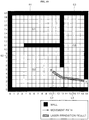
- a map of FIG. 7 represents an actual space as it is, and thus, hereinafter, a laser being output is marked through the map.
- FIG. 8 illustrates a process of outputting a path with a laser by a laser irradiation module of G1 according to an embodiment of the present disclosure.
- the laser irradiation module of G1 may output a path where the robot is capable of travelling as indicated by L1.
- An output of L1 may be made according to the control of the main server 100 from (2, 14) to (2, 11).
- the laser sensor of the robot R may identify a laser output onto the floor, and the robot R may travel from (2, 14) to (2, 11).
- the main server 100 may control also G2 to output a route with a laser. For example, when the robot R reaches a point (2, 12), the main server 100 may control the laser irradiation module of G2, which will be described with reference to FIG. 9 .
- FIG. 9 illustrates a process of outputting a path with a laser by a laser irradiation module of G2 according to an embodiment of the present disclosure.
- the laser irradiation module of G2 may output a path where the robot is capable of moving as indicated by L2.
- An output of L2 may be made according to the control of the main server 100 from (2, 10) to (13, 3).
- the laser sensor of the robot R may identify a laser output onto the floor, and the robot R may move from (2, 10) to (13, 3).
- the main server 100 may stop the laser output of the laser irradiation module of G1 so that L1 is no longer marked on the ground.
- the main server 100 may control also G3 to output a path with a laser. For example, when the robot R reaches a point (12, 4), the main server 100 may control the laser irradiation module of G3, which will be described with reference to FIG. 10 .
- FIG. 10 illustrates a process of outputting a route with a laser by a laser irradiation module of G3 according to an embodiment of the present disclosure.
- a result L2 of laser irradiation previously performed by G2 may be marked only in a travel direction of the robot as the robot moves, and the main server 100 may control G2 so that a previous region which the robot passed is not irradiated with a laser.
- FIG. 10 illustrates a partial output result of L2.
- L3 is output to the destination X by G3.
- the robot may reach the destination X as a result of traveling to a region of 63 and continuously sensing L3.
- the robot may sense the path and move at a high speed.
- the three camera modules may photograph the travel direction of the robot in real time during the travel of the robot, thereby being capable of identifying the current location of the robot.
- the obstacle sensor 256 of the laser irradiation module 200 may identify a signal being returned while outputting a route onto the ground, and when it is determined that an object is closer than the original ground, the obstacle sensor 256 may determine that an obstacle is disposed. The obstacle sensor 256 may notify the main server 100 that the obstacle is disposed. In this situation, the main server 100 may recalculate the path.
- a route may be generated primarily in FIGS. 8 to 10 .
- the generated path may be immediately corrected by the main server 100 and newly output onto the ground.
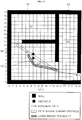
- FIG. 11 illustrates a result of correcting a path according to an embodiment of the present disclosure.
- an obstacle may be sensed by the camera module or the laser irradiation module while the robot is travelling.
- the camera module of G2 may sense an obstacle which is disposed within a range in which the camera module of G2 is capable of photographing, and the camera G2 may transmit sensed information about the obstacle to the main server 100.
- the controller 150 of the main server 100 may generate a movement path of the robot by using the sensed information.
- the sensed information indicates that an image including a different object in comparison with a previously photographed image is photographed.
- the controller 150 may identify that an obstacle is disposed by using the depth information.
- the controller 150 may compare a first image previously photographed by the camera module with a second image photographed by the camera module at the present time point, and may analyze a region where a difference occurs therebetween to calculate sensed information indicating that an obstacle is disposed.
- the controller 150 may calculate a difference between two images generated by an RGB camera module or a difference between depth information of two images generated by a depth camera module.
- the controller 150 may compare images photographed in the same direction and at the same magnification without conversion.
- the controller 150 may compare two images through constant conversion when the images are photographed in different directions or at different magnifications.
- the laser irradiation module of G2 may sense obstacle which is disposed within an irradiation range in which the laser irradiation module of G2 is capable of irradiating a laser, and the laser irradiation module of G2 may transmit sensed information about the obstacle to the main server 100.
- the controller 150 of the main server 100 may generate a movement path of the robot by using the sensed information.
- the sensed information indicates that an object is newly disposed by reflecting a laser at a position higher than the ground in the process of irradiating a laser. That is, the controller 150 may store information about heights of respective objects in a laser irradiation region.
- the controller 150 may store first height information of objects acquired by the laser irradiation module in the laser irradiation region at a first time point and second height information of objects acquired by the laser irradiation module in the laser irradiation region at a second time point. The controller 150 may compare the first height information and the second height information to identify that an object is newly placed or removed. In addition, the controller 150 may determine that a new obstacle is disposed according to changes in heights of objects.
- the controller 150 may identify a location of an obstacle that is initially disposed by using information acquired by the camera module and the laser irradiation module to generate a movement path. In addition, the controller 150 may identify a location of a changed obstacle or a location of a newly added obstacle, and may generate a movement path.
- the guiding device G2 may transmit location information of a sensed obstacle to the main server 100.
- the main server 100 may reconfigure a path.
- G2 may output a laser along paths of L2_1 and L2_2.
- the main server 100 may generate a new path in consideration of a speed and a possible rotational angular velocity of the robot while the robot is travelling so that the robot avoids obstacles.
- the main server 100 may control the view angle adjusting unit 214 of the camera so that the camera photographs the laser irradiation region to track a moving process of the robot.
- the view angle adjusting unit 214 of the camera may be controlled by the main server 100 to photograph the laser irradiation region while tracking the robot in response to the movement of the robot.
- FIG. 12 illustrates a moving process of a robot according to an embodiment of the present disclosure.
- the two guiding devices 200a and 200b may be disposed on the ceiling of FIG. 12 .
- Each of the guiding devices 200a and 200b may include the camera modules 210a and 210b, the laser irradiation modules 250a and 250b, and communication units 280a and 280b.
- the first guiding device 200a corresponding to G1 may recognize and photograph the mark 390 of the robot 300 by vision sensing in step S34, and may transmit a photographed image via the communication unit 280a to the main server 100.
- the laser irradiation module 250 may irradiate a laser as indicated by L1 in steps S53a and S53b.
- the robot 300 may travel a distance corresponding to L1 along the sensed laser at a high speed.
- the second guiding device 200b may output a route as indicated by L2 in steps S53c and S53d.
- the main server 100 first may generate a path and transmit information of the path to the two guiding devices 200a and 200b, and the two laser irradiation modules 250a and 250b may simultaneously output L1 and L2, thereby being capable of allowing the robot 300 to move at a high speed.
- the changed location of the robot may be continuously photographed by the camera modules 210a and 210b while the robot is moving.
- the communication unit 180 of the main server 100 may receive an image including the changed location of the robot from the camera modules 210a and 210b.
- the controller 150 of the main server 100 may select a second laser irradiation module to output a laser in response to the movement path of the robot.
- the main server 100 may control transmission of the movement path to the selected second laser irradiation module. Therefore, when a plurality of laser irradiation modules is disposed in a large space, the main server 100 may generate a movement path for each region and transmit the generated movement paths to the laser irradiation modules.
- FIG. 13 illustrates an example of a laser output reflecting characteristics of a movement path according to an embodiment of the present disclosure.
- the laser irradiation module may output a laser in the shape of a line or a dot according to instructions of the controller 150 of the main server 100. Further, in order to control the speed, a width of the line may be reduced or a size of the dot may be modified.
- a color or frequency of the output laser may be adjusted differently in outputting a route with a laser so that each of the robots travels the route.
- a method for outputting a path with a laser may be divided into a line output method and a dot output method.
- a driving direction is an arrow direction based on the robot R
- an output shape of the laser marked in front of the robot may be different according to the speed.
- the laser irradiation module may output a route with a laser without difference in a width of a line. Conversely, in the situation of a speed-reducing path based on the line output method, the laser irradiation module may output a laser so that the width of the line is reduced. As a result, the robot may slow down when the width of the line decreases while the robot travels along the path output with the laser.
- the laser irradiation module may output a path with a laser in a dot shape having a predetermined size.
- the laser irradiation module may output a laser so that a spacing of dots increases or lengths of the dots decrease.
- the robot may slow down when the spacing of the dots increases or the lengths of the dots decrease while the root travels along the route output with the laser.
- FIG. 13 is an example, and the width of the line may be adjusted to be inversely proportional to the moving speed, and sizes or spacing of the dots may also be output as opposed to the example of FIG. 13 .
- the main server 100 may store physical characteristics (color, frequency) of a laser to be output for each robot in advance, and may allow the laser irradiation module to output the laser with different colors, different frequencies, or different wavelengths for each robot.
- the physical characteristics of the laser shape, color, wavelength, frequency, and the like may be set in various ways.
- Such information may be also transmitted to robots.
- a robot senses a laser on the ground, when a color or frequency of the sensed laser is not a color or frequency assigned to itself, the robot may not travel along a route output onto the ground.
- This implementation may prevent a robot from traveling along a path of another robot when a large number of robots are disposed in a space.
- this configuration may allow the robots not to recognize the unauthorized laser signal as a route.
- the controller 150 of the main server 100 may control physical characteristics of an output laser of the laser irradiation module in response to the robot.
- the controller 350 of the robot 300 may determine whether a laser output according to physical characteristics of a laser sensed by the laser sensor 310 is corresponding to the robot 300, and the controller 350 may control the driving unit 320 if the physical characteristics of a laser are matched or suitable to robot 300.
- physical characteristics of a laser for marking a movement path on the ground may include any one or more among a shape, wavelength, frequency, color, and the like of the output laser. That is, it is possible to control the travel speed of the robot by configuring these physical characteristics in various ways.
- FIG. 14 illustrates an example of laser irradiation when two marks are disposed on a robot according to an embodiment of the present disclosure.
- FIG. 14 illustrates a state in which a first mark 390a indicating a location of the laser sensor 310 and a second mark 390b indicating a location of a back surface or rear of the robot are disposed on an upper surface of the robot.
- the main server may identify that a path where the robot will move is at the back (arrow direction). However, instead of commanding the robot to move backward, the main server may control the robot to move backward (arrow direction) along the path by scanning the path toward the laser sensor 310 as indicated by L4. As illustrated in FIG. 14 , forward and backward directions of the robot may be identified by using two types of marks, thereby being capable of more flexibly irradiating a movement path for controlling the travel of the robot onto the ground of the robot.
- a path where the robot needs to follow may be irradiated with a laser (for example, a line laser or a dot laser) on the floor surface.
- a laser for example, a line laser or a dot laser
- the main server interlocked with the camera performs all calculations to provide the robot with a path that is a final result.
- the camera may recognize the robot and provide information right in front of the robot via a pan-tilt motion, thereby being capable of using immediately recognizable sensor arrays instead of a vision that requires a lot of calculations.
- the robot since the robot does not need to perform complicated calculations related to move and the provided path reflects the characteristics of the robot, the robot may perform stable driving even at a high speed without deviation from the path. Further, since the provided information is continuous information such as lines or dots, the robot may stably maintain an operation thereof. In addition, since the robot does not need to rapidly change a direction unless there is a large deviation from the route, it is suitable for high-speed travel.
- a target point is provided with a point laser, and thus the related art is a technology to provide only a final destination far away from a robot as a point. Therefore, the rest of tasks, such as obstacle recognition and route calculation, should be done by the robot itself, and the robot should be equipped with computing power for this purpose.
- the robot may not make a long-term plan for movement, and perform a reactive operation to recalculate on each occasion according to a location of a point. Therefore, there is a technical limitation in that the operation is disconnected when a calculation speed is not fast enough.
- a path itself where the robot needs to follow may be irradiated with a line laser, a dot laser, or the like onto the ground of the travel direction of the robot. All calculations required for this configuration may be performed by a system interlocked with the camera to provide the robot with a path that is a final result, thereby being capable of allowing the robot to move in a quickly manner.
- the robot may move based on route information provided from the outside even when the robot cannot accurately be aware of an absolute location in a space.
- the point may be information for travelling to a specific location in a space, but such point marking may not provide route information for travelling to a corresponding location.
- a route or path for the robot may be marked so that obstacles are avoided and the robot may identify the marked route or path and travel at a high speed.
- the camera module and the laser irradiation module disposed on the wall or the ceiling may identify obstacles disposed in the travel direction of the robot, and thus a movement path may be corrected again even after the movement path is generated.
- modules configured to irradiate light having various wavelengths which can be sensed by the robot all correspond to the laser irradiation module of the present disclosure.
- the movement path may be irradiated with a laser onto the ground in response to the location of the robot, and accordingly the robot may sense and travel the irradiated movement path.
- the main server may identify the location of the robot via the camera module, calculate a route required for the robot to travel, and transmit the calculated route to the laser irradiation module.
- the main server may identify obstacles disposed around the robot by using the camera module and the laser irradiation module, and may recalculate the route based thereon.
- the present disclosure is not necessarily limited to such embodiments. That is, all the elements may be selectively integrated into one or more and be operated as one or more within the scope of the present disclosure. Further, each of the elements may be implemented as independent hardware. Alternatively, some or all of the elements may be selectively combined to be implemented as a computer program having a program module performing some or all functions combined in one or more pieces of hardware. Codes and code segments constituting the computer program may be easily inferred by those skilled in the art to which the present disclosure belongs.
- the computer program is stored in computer readable media such that the computer program is read and executed by a computer to implement embodiments of the present disclosure. Examples of the storage media of the computer program may include magnetic recording media, optical recording media, and a semiconductor storage device. Further, the computer program implementing the embodiments of the present disclosure may include a program module transmitted in real-time via an external device.
Landscapes
- Engineering & Computer Science (AREA)
- Physics & Mathematics (AREA)
- Aviation & Aerospace Engineering (AREA)
- Radar, Positioning & Navigation (AREA)
- Remote Sensing (AREA)
- General Physics & Mathematics (AREA)
- Automation & Control Theory (AREA)
- Electromagnetism (AREA)
- Optics & Photonics (AREA)
- Computer Vision & Pattern Recognition (AREA)
- Multimedia (AREA)
- Mechanical Engineering (AREA)
- Robotics (AREA)
- Control Of Position, Course, Altitude, Or Attitude Of Moving Bodies (AREA)
Applications Claiming Priority (1)
| Application Number | Priority Date | Filing Date | Title |
|---|---|---|---|
| KR1020180150838A KR102065521B1 (ko) | 2018-11-29 | 2018-11-29 | 로봇의 이동 경로의 레이저 조사를 제어하는 서버와 방법 및 이에 기반하여 이동하는 로봇 |
Publications (2)
| Publication Number | Publication Date |
|---|---|
| EP3674830A1 true EP3674830A1 (de) | 2020-07-01 |
| EP3674830B1 EP3674830B1 (de) | 2021-01-20 |
Family
ID=68696220
Family Applications (1)
| Application Number | Title | Priority Date | Filing Date |
|---|---|---|---|
| EP19210919.7A Active EP3674830B1 (de) | 2018-11-29 | 2019-11-22 | Server und verfahren zur steuerung der laserbestrahlung der bewegungsbahn eines roboters und roboter, der sich darauf basierend bewegt |
Country Status (3)
| Country | Link |
|---|---|
| US (1) | US11513525B2 (de) |
| EP (1) | EP3674830B1 (de) |
| KR (1) | KR102065521B1 (de) |
Cited By (1)
| Publication number | Priority date | Publication date | Assignee | Title |
|---|---|---|---|---|
| WO2022027869A1 (zh) * | 2020-08-02 | 2022-02-10 | 珠海一微半导体股份有限公司 | 一种基于边界的机器人区域划分方法、芯片及机器人 |
Families Citing this family (12)
| Publication number | Priority date | Publication date | Assignee | Title |
|---|---|---|---|---|
| WO2020256179A1 (ko) * | 2019-06-18 | 2020-12-24 | 엘지전자 주식회사 | 공간 인식을 위한 마커, 공간을 인식하여 카트로봇을 정렬하고 이동시키는 방법 및 카트로봇 |
| US11693420B2 (en) | 2019-08-09 | 2023-07-04 | Universal City Studios Llc | Vehicle guidance via infrared projection |
| US11797016B2 (en) | 2020-04-13 | 2023-10-24 | Boston Dynamics, Inc. | Online authoring of robot autonomy applications |
| KR20220019930A (ko) | 2020-08-11 | 2022-02-18 | 삼성전자주식회사 | 로봇 및 그 제어 방법 |
| CN112417646B (zh) * | 2020-10-20 | 2023-11-17 | 湖南华曙高科技股份有限公司 | 基于奇数多激光器的扫描路径规划方法、装置以及三维物体制造设备 |
| JP2022077067A (ja) * | 2020-11-11 | 2022-05-23 | 前田建設工業株式会社 | 会議用什器の自動配置システム |
| WO2022256818A1 (en) * | 2021-06-04 | 2022-12-08 | Boston Dynamics, Inc. | Autonomous and teleoperated sensor pointing on a mobile robot |
| CN114779763B (zh) * | 2022-03-31 | 2024-12-06 | 惠州拓邦电气技术有限公司 | 机器人导航系统和机器人移动轨迹控制方法 |
| CN117122245A (zh) * | 2022-05-18 | 2023-11-28 | 科大讯飞股份有限公司 | 机器人控制方法、机器人、机器人控制系统及存储介质 |
| EP4710178A1 (de) | 2023-05-08 | 2026-03-18 | Boston Dynamics, Inc. | Ortsabhängige änderungsdetektion in bilddaten durch einen mobilen roboter |
| CN116985155A (zh) * | 2023-07-25 | 2023-11-03 | 成都圭目机器人有限公司 | 船舶梯口智能监护机器人 |
| KR102887967B1 (ko) * | 2023-10-30 | 2025-11-24 | 주식회사 쓰리세컨즈 | 차선 생성 시스템, 차선 생성 방법 및 차선 생성 서버 |
Citations (2)
| Publication number | Priority date | Publication date | Assignee | Title |
|---|---|---|---|---|
| US20020027652A1 (en) * | 2000-06-29 | 2002-03-07 | Paromtchik Igor E. | Method for instructing target position for mobile body, method for controlling transfer thereof, and method as well as system of optical guidance therefor |
| CN107063257A (zh) * | 2017-02-05 | 2017-08-18 | 安凯 | 一种分离式扫地机器人及其路径规划方法 |
Family Cites Families (5)
| Publication number | Priority date | Publication date | Assignee | Title |
|---|---|---|---|---|
| KR100948947B1 (ko) * | 2008-01-16 | 2010-03-23 | 한국생산기술연구원 | 이동체의 위치 추정 장치 및 그 방법 |
| KR101305401B1 (ko) * | 2012-02-15 | 2013-09-05 | 한국과학기술연구원 | 적외선 라인 레이저를 이용한 무인주행차량의 야간 주행 유도 시스템 및 방법 |
| JP5958304B2 (ja) * | 2012-11-29 | 2016-07-27 | トヨタ自動車株式会社 | 駐車支援装置 |
| CN104867158B (zh) * | 2015-06-03 | 2017-09-29 | 武汉理工大学 | 基于单目视觉的室内水面船舶精确定位系统和方法 |
| JP2018073027A (ja) * | 2016-10-27 | 2018-05-10 | 国立大学法人九州工業大学 | 無人搬送車ガイドシステム及びガイド方法 |
-
2018
- 2018-11-29 KR KR1020180150838A patent/KR102065521B1/ko active Active
-
2019
- 2019-11-22 EP EP19210919.7A patent/EP3674830B1/de active Active
- 2019-11-26 US US16/696,719 patent/US11513525B2/en active Active
Patent Citations (2)
| Publication number | Priority date | Publication date | Assignee | Title |
|---|---|---|---|---|
| US20020027652A1 (en) * | 2000-06-29 | 2002-03-07 | Paromtchik Igor E. | Method for instructing target position for mobile body, method for controlling transfer thereof, and method as well as system of optical guidance therefor |
| CN107063257A (zh) * | 2017-02-05 | 2017-08-18 | 安凯 | 一种分离式扫地机器人及其路径规划方法 |
Non-Patent Citations (1)
| Title |
|---|
| WEN-CHUNG CHANG ET AL: "Vision-based robot navigation and map building using active laser projection", SYSTEM INTEGRATION (SII), 2011 IEEE/SICE INTERNATIONAL SYMPOSIUM ON, IEEE, 20 December 2011 (2011-12-20), pages 24 - 29, XP032112652, ISBN: 978-1-4577-1523-5, DOI: 10.1109/SII.2011.6147413 * |
Cited By (2)
| Publication number | Priority date | Publication date | Assignee | Title |
|---|---|---|---|---|
| WO2022027869A1 (zh) * | 2020-08-02 | 2022-02-10 | 珠海一微半导体股份有限公司 | 一种基于边界的机器人区域划分方法、芯片及机器人 |
| US12147239B2 (en) | 2020-08-02 | 2024-11-19 | Amicro Semiconductor Co., Ltd. | Method for dividing robot area based on boundaries, chip and robot |
Also Published As
| Publication number | Publication date |
|---|---|
| EP3674830B1 (de) | 2021-01-20 |
| US20200174484A1 (en) | 2020-06-04 |
| KR102065521B1 (ko) | 2020-01-13 |
| US11513525B2 (en) | 2022-11-29 |
Similar Documents
| Publication | Publication Date | Title |
|---|---|---|
| EP3674830B1 (de) | Server und verfahren zur steuerung der laserbestrahlung der bewegungsbahn eines roboters und roboter, der sich darauf basierend bewegt | |
| KR102583386B1 (ko) | 랙 다리 식별을 사용하여 통로 밖 위치 파악 및 차량 위치 교정을 위한 시스템 및 방법 | |
| CN114585875B (zh) | 计量系统 | |
| US9758239B2 (en) | System and method for controlling an unmanned air vehicle | |
| CA2832956C (en) | System and method for controlling an unmanned aerial vehicle | |
| US8090193B2 (en) | Mobile robot | |
| WO2020258721A1 (zh) | 智能巡航车导航方法及系统 | |
| KR20210034602A (ko) | 랙 레그 식별을 사용한 차량 위치 교정을 위한 시스템 및 방법 | |
| US11500391B2 (en) | Method for positioning on basis of vision information and robot implementing same | |
| KR20130067851A (ko) | 차량 위치 인식 장치 및 방법 | |
| KR102179238B1 (ko) | 장치의 사람 추종 주행 및 자율 주행 방법 | |
| TW202105109A (zh) | 移動機器人、移動機器人之控制系統及移動機器人之控制方法 | |
| KR101305401B1 (ko) | 적외선 라인 레이저를 이용한 무인주행차량의 야간 주행 유도 시스템 및 방법 | |
| US11353885B2 (en) | Method of acquiring image for recognizing position and robot implementing the same | |
| JP4530996B2 (ja) | 移動ロボット | |
| KR102349044B1 (ko) | 로봇의 이동 경로의 레이저 조사를 제어하는 서버와 방법 및 이에 기반하여 이동하는 로봇 | |
| JP4377346B2 (ja) | 移動ロボット | |
| KR102081093B1 (ko) | 모바일 로봇 네비게이션 시스템 | |
| JP2020135497A (ja) | 自動搬送車誘導システム及び自動搬送車誘導方法 | |
| WO2019069921A1 (ja) | 移動体 | |
| RU227202U1 (ru) | Устройство для ориентирования автономного мобильного робота по видеопотокам в оптическом диапазоне | |
| US20260029792A1 (en) | Autonomous mobile robot and system for controlling autonomous mobile robot | |
| JPWO2018180175A1 (ja) | 移動体、信号処理装置およびコンピュータプログラム | |
| US11402846B2 (en) | Method, system and apparatus for mitigating data capture light leakage | |
| JP2018185768A (ja) | 自律移動ロボット |
Legal Events
| Date | Code | Title | Description |
|---|---|---|---|
| PUAI | Public reference made under article 153(3) epc to a published international application that has entered the european phase |
Free format text: ORIGINAL CODE: 0009012 |
|
| STAA | Information on the status of an ep patent application or granted ep patent |
Free format text: STATUS: THE APPLICATION HAS BEEN PUBLISHED |
|
| AK | Designated contracting states |
Kind code of ref document: A1 Designated state(s): AL AT BE BG CH CY CZ DE DK EE ES FI FR GB GR HR HU IE IS IT LI LT LU LV MC MK MT NL NO PL PT RO RS SE SI SK SM TR |
|
| AX | Request for extension of the european patent |
Extension state: BA ME |
|
| STAA | Information on the status of an ep patent application or granted ep patent |
Free format text: STATUS: REQUEST FOR EXAMINATION WAS MADE |
|
| 17P | Request for examination filed |
Effective date: 20200626 |
|
| RBV | Designated contracting states (corrected) |
Designated state(s): AL AT BE BG CH CY CZ DE DK EE ES FI FR GB GR HR HU IE IS IT LI LT LU LV MC MK MT NL NO PL PT RO RS SE SI SK SM TR |
|
| RIC1 | Information provided on ipc code assigned before grant |
Ipc: G05D 1/02 20200101AFI20200727BHEP |
|
| GRAP | Despatch of communication of intention to grant a patent |
Free format text: ORIGINAL CODE: EPIDOSNIGR1 |
|
| STAA | Information on the status of an ep patent application or granted ep patent |
Free format text: STATUS: GRANT OF PATENT IS INTENDED |
|
| INTG | Intention to grant announced |
Effective date: 20200921 |
|
| GRAS | Grant fee paid |
Free format text: ORIGINAL CODE: EPIDOSNIGR3 |
|
| GRAA | (expected) grant |
Free format text: ORIGINAL CODE: 0009210 |
|
| STAA | Information on the status of an ep patent application or granted ep patent |
Free format text: STATUS: THE PATENT HAS BEEN GRANTED |
|
| AK | Designated contracting states |
Kind code of ref document: B1 Designated state(s): AL AT BE BG CH CY CZ DE DK EE ES FI FR GB GR HR HU IE IS IT LI LT LU LV MC MK MT NL NO PL PT RO RS SE SI SK SM TR |
|
| REG | Reference to a national code |
Ref country code: GB Ref legal event code: FG4D |
|
| REG | Reference to a national code |
Ref country code: CH Ref legal event code: EP |
|
| REG | Reference to a national code |
Ref country code: AT Ref legal event code: REF Ref document number: 1356967 Country of ref document: AT Kind code of ref document: T Effective date: 20210215 |
|
| REG | Reference to a national code |
Ref country code: IE Ref legal event code: FG4D |
|
| REG | Reference to a national code |
Ref country code: DE Ref legal event code: R096 Ref document number: 602019002282 Country of ref document: DE |
|
| REG | Reference to a national code |
Ref country code: NL Ref legal event code: MP Effective date: 20210120 |
|
| REG | Reference to a national code |
Ref country code: LT Ref legal event code: MG9D |
|
| REG | Reference to a national code |
Ref country code: AT Ref legal event code: MK05 Ref document number: 1356967 Country of ref document: AT Kind code of ref document: T Effective date: 20210120 |
|
| PG25 | Lapsed in a contracting state [announced via postgrant information from national office to epo] |
Ref country code: NO Free format text: LAPSE BECAUSE OF FAILURE TO SUBMIT A TRANSLATION OF THE DESCRIPTION OR TO PAY THE FEE WITHIN THE PRESCRIBED TIME-LIMIT Effective date: 20210420 Ref country code: PT Free format text: LAPSE BECAUSE OF FAILURE TO SUBMIT A TRANSLATION OF THE DESCRIPTION OR TO PAY THE FEE WITHIN THE PRESCRIBED TIME-LIMIT Effective date: 20210520 Ref country code: LT Free format text: LAPSE BECAUSE OF FAILURE TO SUBMIT A TRANSLATION OF THE DESCRIPTION OR TO PAY THE FEE WITHIN THE PRESCRIBED TIME-LIMIT Effective date: 20210120 Ref country code: FI Free format text: LAPSE BECAUSE OF FAILURE TO SUBMIT A TRANSLATION OF THE DESCRIPTION OR TO PAY THE FEE WITHIN THE PRESCRIBED TIME-LIMIT Effective date: 20210120 Ref country code: BG Free format text: LAPSE BECAUSE OF FAILURE TO SUBMIT A TRANSLATION OF THE DESCRIPTION OR TO PAY THE FEE WITHIN THE PRESCRIBED TIME-LIMIT Effective date: 20210420 Ref country code: HR Free format text: LAPSE BECAUSE OF FAILURE TO SUBMIT A TRANSLATION OF THE DESCRIPTION OR TO PAY THE FEE WITHIN THE PRESCRIBED TIME-LIMIT Effective date: 20210120 |
|
| PG25 | Lapsed in a contracting state [announced via postgrant information from national office to epo] |
Ref country code: SE Free format text: LAPSE BECAUSE OF FAILURE TO SUBMIT A TRANSLATION OF THE DESCRIPTION OR TO PAY THE FEE WITHIN THE PRESCRIBED TIME-LIMIT Effective date: 20210120 Ref country code: RS Free format text: LAPSE BECAUSE OF FAILURE TO SUBMIT A TRANSLATION OF THE DESCRIPTION OR TO PAY THE FEE WITHIN THE PRESCRIBED TIME-LIMIT Effective date: 20210120 Ref country code: AT Free format text: LAPSE BECAUSE OF FAILURE TO SUBMIT A TRANSLATION OF THE DESCRIPTION OR TO PAY THE FEE WITHIN THE PRESCRIBED TIME-LIMIT Effective date: 20210120 Ref country code: PL Free format text: LAPSE BECAUSE OF FAILURE TO SUBMIT A TRANSLATION OF THE DESCRIPTION OR TO PAY THE FEE WITHIN THE PRESCRIBED TIME-LIMIT Effective date: 20210120 Ref country code: LV Free format text: LAPSE BECAUSE OF FAILURE TO SUBMIT A TRANSLATION OF THE DESCRIPTION OR TO PAY THE FEE WITHIN THE PRESCRIBED TIME-LIMIT Effective date: 20210120 |
|
| PG25 | Lapsed in a contracting state [announced via postgrant information from national office to epo] |
Ref country code: IS Free format text: LAPSE BECAUSE OF FAILURE TO SUBMIT A TRANSLATION OF THE DESCRIPTION OR TO PAY THE FEE WITHIN THE PRESCRIBED TIME-LIMIT Effective date: 20210520 |
|
| REG | Reference to a national code |
Ref country code: DE Ref legal event code: R097 Ref document number: 602019002282 Country of ref document: DE |
|
| PG25 | Lapsed in a contracting state [announced via postgrant information from national office to epo] |
Ref country code: EE Free format text: LAPSE BECAUSE OF FAILURE TO SUBMIT A TRANSLATION OF THE DESCRIPTION OR TO PAY THE FEE WITHIN THE PRESCRIBED TIME-LIMIT Effective date: 20210120 Ref country code: CZ Free format text: LAPSE BECAUSE OF FAILURE TO SUBMIT A TRANSLATION OF THE DESCRIPTION OR TO PAY THE FEE WITHIN THE PRESCRIBED TIME-LIMIT Effective date: 20210120 Ref country code: SM Free format text: LAPSE BECAUSE OF FAILURE TO SUBMIT A TRANSLATION OF THE DESCRIPTION OR TO PAY THE FEE WITHIN THE PRESCRIBED TIME-LIMIT Effective date: 20210120 |
|
| PLBE | No opposition filed within time limit |
Free format text: ORIGINAL CODE: 0009261 |
|
| STAA | Information on the status of an ep patent application or granted ep patent |
Free format text: STATUS: NO OPPOSITION FILED WITHIN TIME LIMIT |
|
| PG25 | Lapsed in a contracting state [announced via postgrant information from national office to epo] |
Ref country code: DK Free format text: LAPSE BECAUSE OF FAILURE TO SUBMIT A TRANSLATION OF THE DESCRIPTION OR TO PAY THE FEE WITHIN THE PRESCRIBED TIME-LIMIT Effective date: 20210120 Ref country code: SK Free format text: LAPSE BECAUSE OF FAILURE TO SUBMIT A TRANSLATION OF THE DESCRIPTION OR TO PAY THE FEE WITHIN THE PRESCRIBED TIME-LIMIT Effective date: 20210120 Ref country code: RO Free format text: LAPSE BECAUSE OF FAILURE TO SUBMIT A TRANSLATION OF THE DESCRIPTION OR TO PAY THE FEE WITHIN THE PRESCRIBED TIME-LIMIT Effective date: 20210120 |
|
| 26N | No opposition filed |
Effective date: 20211021 |
|
| PG25 | Lapsed in a contracting state [announced via postgrant information from national office to epo] |
Ref country code: AL Free format text: LAPSE BECAUSE OF FAILURE TO SUBMIT A TRANSLATION OF THE DESCRIPTION OR TO PAY THE FEE WITHIN THE PRESCRIBED TIME-LIMIT Effective date: 20210120 Ref country code: ES Free format text: LAPSE BECAUSE OF FAILURE TO SUBMIT A TRANSLATION OF THE DESCRIPTION OR TO PAY THE FEE WITHIN THE PRESCRIBED TIME-LIMIT Effective date: 20210120 |
|
| PG25 | Lapsed in a contracting state [announced via postgrant information from national office to epo] |
Ref country code: IT Free format text: LAPSE BECAUSE OF FAILURE TO SUBMIT A TRANSLATION OF THE DESCRIPTION OR TO PAY THE FEE WITHIN THE PRESCRIBED TIME-LIMIT Effective date: 20210120 |
|
| PG25 | Lapsed in a contracting state [announced via postgrant information from national office to epo] |
Ref country code: IS Free format text: LAPSE BECAUSE OF FAILURE TO SUBMIT A TRANSLATION OF THE DESCRIPTION OR TO PAY THE FEE WITHIN THE PRESCRIBED TIME-LIMIT Effective date: 20210520 |
|
| PG25 | Lapsed in a contracting state [announced via postgrant information from national office to epo] |
Ref country code: MC Free format text: LAPSE BECAUSE OF FAILURE TO SUBMIT A TRANSLATION OF THE DESCRIPTION OR TO PAY THE FEE WITHIN THE PRESCRIBED TIME-LIMIT Effective date: 20210120 |
|
| PG25 | Lapsed in a contracting state [announced via postgrant information from national office to epo] |
Ref country code: LU Free format text: LAPSE BECAUSE OF NON-PAYMENT OF DUE FEES Effective date: 20211122 Ref country code: BE Free format text: LAPSE BECAUSE OF NON-PAYMENT OF DUE FEES Effective date: 20211130 |
|
| REG | Reference to a national code |
Ref country code: BE Ref legal event code: MM Effective date: 20211130 |
|
| PG25 | Lapsed in a contracting state [announced via postgrant information from national office to epo] |
Ref country code: IE Free format text: LAPSE BECAUSE OF NON-PAYMENT OF DUE FEES Effective date: 20211122 |
|
| PG25 | Lapsed in a contracting state [announced via postgrant information from national office to epo] |
Ref country code: FR Free format text: LAPSE BECAUSE OF NON-PAYMENT OF DUE FEES Effective date: 20211130 |
|
| PG25 | Lapsed in a contracting state [announced via postgrant information from national office to epo] |
Ref country code: CY Free format text: LAPSE BECAUSE OF FAILURE TO SUBMIT A TRANSLATION OF THE DESCRIPTION OR TO PAY THE FEE WITHIN THE PRESCRIBED TIME-LIMIT Effective date: 20210120 |
|
| REG | Reference to a national code |
Ref country code: CH Ref legal event code: PL |
|
| PG25 | Lapsed in a contracting state [announced via postgrant information from national office to epo] |
Ref country code: LI Free format text: LAPSE BECAUSE OF NON-PAYMENT OF DUE FEES Effective date: 20221130 Ref country code: HU Free format text: LAPSE BECAUSE OF FAILURE TO SUBMIT A TRANSLATION OF THE DESCRIPTION OR TO PAY THE FEE WITHIN THE PRESCRIBED TIME-LIMIT; INVALID AB INITIO Effective date: 20191122 Ref country code: GR Free format text: LAPSE BECAUSE OF FAILURE TO SUBMIT A TRANSLATION OF THE DESCRIPTION OR TO PAY THE FEE WITHIN THE PRESCRIBED TIME-LIMIT Effective date: 20210120 Ref country code: CH Free format text: LAPSE BECAUSE OF NON-PAYMENT OF DUE FEES Effective date: 20221130 |
|
| PG25 | Lapsed in a contracting state [announced via postgrant information from national office to epo] |
Ref country code: SI Free format text: LAPSE BECAUSE OF FAILURE TO SUBMIT A TRANSLATION OF THE DESCRIPTION OR TO PAY THE FEE WITHIN THE PRESCRIBED TIME-LIMIT Effective date: 20210120 |
|
| REG | Reference to a national code |
Ref country code: DE Ref legal event code: R079 Ref document number: 602019002282 Country of ref document: DE Free format text: PREVIOUS MAIN CLASS: G05D0001020000 Ipc: G05D0001430000 |
|
| PG25 | Lapsed in a contracting state [announced via postgrant information from national office to epo] |
Ref country code: MK Free format text: LAPSE BECAUSE OF FAILURE TO SUBMIT A TRANSLATION OF THE DESCRIPTION OR TO PAY THE FEE WITHIN THE PRESCRIBED TIME-LIMIT Effective date: 20210120 |
|
| PG25 | Lapsed in a contracting state [announced via postgrant information from national office to epo] |
Ref country code: TR Free format text: LAPSE BECAUSE OF FAILURE TO SUBMIT A TRANSLATION OF THE DESCRIPTION OR TO PAY THE FEE WITHIN THE PRESCRIBED TIME-LIMIT Effective date: 20210120 |
|
| GBPC | Gb: european patent ceased through non-payment of renewal fee |
Effective date: 20231122 |
|
| PG25 | Lapsed in a contracting state [announced via postgrant information from national office to epo] |
Ref country code: MT Free format text: LAPSE BECAUSE OF FAILURE TO SUBMIT A TRANSLATION OF THE DESCRIPTION OR TO PAY THE FEE WITHIN THE PRESCRIBED TIME-LIMIT Effective date: 20210120 |
|
| PG25 | Lapsed in a contracting state [announced via postgrant information from national office to epo] |
Ref country code: GB Free format text: LAPSE BECAUSE OF NON-PAYMENT OF DUE FEES Effective date: 20231122 |
|
| PG25 | Lapsed in a contracting state [announced via postgrant information from national office to epo] |
Ref country code: GB Free format text: LAPSE BECAUSE OF NON-PAYMENT OF DUE FEES Effective date: 20231122 |
|
| PG25 | Lapsed in a contracting state [announced via postgrant information from national office to epo] |
Ref country code: NL Free format text: LAPSE BECAUSE OF FAILURE TO SUBMIT A TRANSLATION OF THE DESCRIPTION OR TO PAY THE FEE WITHIN THE PRESCRIBED TIME-LIMIT Effective date: 20210120 |
|
| PGFP | Annual fee paid to national office [announced via postgrant information from national office to epo] |
Ref country code: DE Payment date: 20251002 Year of fee payment: 7 |