EP3674904B1 - Dispositif électronique ayant une interface usb de type c, procédé de commande pour interface usb de type c, et support d'informations - Google Patents
Dispositif électronique ayant une interface usb de type c, procédé de commande pour interface usb de type c, et support d'informations Download PDFInfo
- Publication number
- EP3674904B1 EP3674904B1 EP17926441.1A EP17926441A EP3674904B1 EP 3674904 B1 EP3674904 B1 EP 3674904B1 EP 17926441 A EP17926441 A EP 17926441A EP 3674904 B1 EP3674904 B1 EP 3674904B1
- Authority
- EP
- European Patent Office
- Prior art keywords
- type
- usb interface
- external device
- electronic device
- processor
- Prior art date
- Legal status (The legal status is an assumption and is not a legal conclusion. Google has not performed a legal analysis and makes no representation as to the accuracy of the status listed.)
- Active
Links
Images


Classifications
-
- G—PHYSICS
- G06—COMPUTING OR CALCULATING; COUNTING
- G06F—ELECTRIC DIGITAL DATA PROCESSING
- G06F13/00—Interconnection of, or transfer of information or other signals between, memories, input/output devices or central processing units
- G06F13/38—Information transfer, e.g. on bus
- G06F13/42—Bus transfer protocol, e.g. handshake; Synchronisation
- G06F13/4282—Bus transfer protocol, e.g. handshake; Synchronisation on a serial bus, e.g. I2C bus, SPI bus
-
- G—PHYSICS
- G06—COMPUTING OR CALCULATING; COUNTING
- G06F—ELECTRIC DIGITAL DATA PROCESSING
- G06F13/00—Interconnection of, or transfer of information or other signals between, memories, input/output devices or central processing units
- G06F13/38—Information transfer, e.g. on bus
- G06F13/40—Bus structure
-
- G—PHYSICS
- G06—COMPUTING OR CALCULATING; COUNTING
- G06F—ELECTRIC DIGITAL DATA PROCESSING
- G06F2213/00—Indexing scheme relating to interconnection of, or transfer of information or other signals between, memories, input/output devices or central processing units
- G06F2213/0042—Universal serial bus [USB]
-
- Y—GENERAL TAGGING OF NEW TECHNOLOGICAL DEVELOPMENTS; GENERAL TAGGING OF CROSS-SECTIONAL TECHNOLOGIES SPANNING OVER SEVERAL SECTIONS OF THE IPC; TECHNICAL SUBJECTS COVERED BY FORMER USPC CROSS-REFERENCE ART COLLECTIONS [XRACs] AND DIGESTS
- Y02—TECHNOLOGIES OR APPLICATIONS FOR MITIGATION OR ADAPTATION AGAINST CLIMATE CHANGE
- Y02D—CLIMATE CHANGE MITIGATION TECHNOLOGIES IN INFORMATION AND COMMUNICATION TECHNOLOGIES [ICT], I.E. INFORMATION AND COMMUNICATION TECHNOLOGIES AIMING AT THE REDUCTION OF THEIR OWN ENERGY USE
- Y02D10/00—Energy efficient computing, e.g. low power processors, power management or thermal management
Definitions
- This application relates to the field of communications technologies, and in particular, to an electronic device having a Type C USB interface and a method for controlling a Type C USB interface.
- the terminal With continuous development of science and technologies, terminals (such as smartphones) become an irreplaceable part of life.
- the terminal usually has a plurality of interfaces, such as a universal serial bus (Universal Serial Bus, USB) interface and a headset jack. Data transmission, terminal charging, and the like are implemented by using the foregoing interfaces.
- USB Universal Serial Bus
- Document US 9 146 888 B2 discloses an accessory configured to charge a host device, the accessory comprising: a connector having a plurality of contacts, wherein the plurality of contacts includes at least one power contact and at least one data contact and wherein the connector is configured to couple the accessory to a host device; and power control circuitry coupled to the connector, the power control circuitry providing first, second and third modes of operation that determine current and voltage provided to the power contact, wherein in the first mode of operation current provided to the power contact is limited to a first current level and voltage at the power contact is limited to a first voltage level, in the second mode of operation current provided to the power contact is limited to the first current level and voltage at the power contact is increased from the first voltage level to a second voltage level, and in the third mode of operation, current provided to the power contact is increased from the first current level to a second current level while voltage at the power contact is maintained at or above the second voltage level to charge the host device; wherein the power control circuitry is configured to operate in the first mode of operation upon start-up of
- the USB interface of the terminal is usually a micro USB interface or a type-C universal interface.
- a pulse signal is output to a CC pin of a Type C USB interface, to identify a type of an external device plugged into the Type C USB interface.
- the terminal device when the terminal device is in a power-on state, the terminal may continuously output the pulse signal to the CC pin of the Type C USB interface, causing continuous charging of the CC pin of the Type C USB interface. Therefore, this not only wastes power of the terminal, but also brings security risks (such as short circuit and corrosion caused by liquid in the interface) to the terminal.
- Embodiments of this application provide an electronic device having a Type C USB interface as in claim 1 and a method for controlling a Type C USB as in claim 7 to resolve problems of security risks and terminal power waste caused by continuous charging of an interface of a terminal.
- an embodiment of this application provides an electronic device.
- the electronic device includes a Type C USB interface, where the Type C USB interface has a shielding housing.
- the electronic device further includes a processor, where the processor is connected to the Type C USB interface; the Type C USB interface is configured to connect to an external device; the shielding housing of the Type C USB interface is disconnected from a ground signal of the electronic device and is connected to a first resistor and a second resistor, wherein the first resistor and the second resistor are configured to divide a voltage to generate a divided voltage and to apply the divided voltage to the shielding housing of the Type C USB interface; when no external device is connected to the Type C USB interface, a level of the shielding housing of the Type C USB interface is a first level, where the first level is greater than 0; when the external device is connected to the Type C USB interface, the processor outputs a signal to a CC pin of the Type C USB interface; and when no external device is connected to the Type C USB interface, the processor stops outputting the signal to the
- the electronic device further comprises a first comparator; a first positive input end of the first comparator is connected to the shielding housing of the Type C USB interface; a first negative input end of the first comparator is connected to a first reference voltage; a first output end of the first comparator is connected to the processor; the first comparator is configured to compare a voltage level of the first positive input end with a voltage level of the first negative input end and output a first comparison signal to the processor; and the processor is configured to determine, based on the first comparison signal, that the external device is unplugged from the Type C USB interface and/or that the external device is connected to the Type C USB interface; or the processor comprises an ADC detection module, and the ADC detection module is connected to the shielding housing of the Type C USB interface; the ADC detection module is configured to detect the voltage level of the shielding housing of the Type C USB interface; and the processor is configured to determine, based on the voltage level detected by the ADC detection module, that the external device is unplugged from the Type C USB interface, and/or that the external device
- the signal when it is determined that the external device is plugged into the Type C USB interface of the electronic device, the signal is output to the CC pin of the Type C USB interface; and when it is determined that the external device is unplugged from the Type C USB interface of the electronic device, that no external device is connected to the Type C USB interface of the electronic device, or that there is liquid or stains in the Type C USB interface of the electronic device, outputting of the signal to the CC pin of the Type C USB interface is stopped. Therefore, problems of power losses and security risks (such as short circuit and corrosion caused by the liquid in the interface) caused by continuous charging of the CC pin of the Type C USB interface are effectively alleviated.
- the electronic device further includes a power delivery, PD, module, where the processor is connected to the Type C USB interface by using the PD module.
- the processor is specifically configured to: when the external device is connected to the Type C USB interface, control the PD module to output the signal to the CC pin of the Type C USB interface; and when no external device is connected to the Type C USB interface, control the PD module to stop outputting the signal to the CC pin of the Type C USB interface.
- the processor is further configured to: output first prompt information when the external device is unplugged from the Type C USB interface, where the first prompt information is used to inform that the external device is unplugged from the Type C USB interface; and/or output second prompt information when the external device is connected to the Type C USB interface, where the second prompt information is used to inform that the external device is connected to the Type C USB interface.
- the prompt information is used to inform a user that the external device is plugged or unplugged, improving user experience.
- the processor is further configured to stop outputting the signal to the CC pin of the Type C USB interface when there is liquid or stains in the Type C USB interface.
- outputting of the signal to the CC pin of the Type C USB interface is stopped when there is liquid or stains in the Type C USB interface, so that problems of power losses and security risks (such as short circuit and corrosion caused by liquid in the interface) caused by continuous charging of the CC pin of the Type C USB interface are effectively alleviated.
- the processor is further configured to output third prompt information, and the third prompt information is used to inform that there is liquid or stains in the Type C USB interface.
- the electronic device further includes a second comparator, where a second negative input end of the second comparator is connected to the shielding housing of the Type C USB interface; a second positive input end of the second comparator is connected to a second reference voltage; a second output end of the second comparator is connected to the processor; the first comparator is configured to compare a voltage level of the second positive input end with a voltage level of the second negative input end and output a second comparison signal to the processor; and the processor is configured to determine, based on the first comparison signal and the second comparison signal, that the external device is unplugged from the Type C USB interface, and/or that the external device is connected to the Type C USB interface, and/or that there is liquid or stains in the Type C USB interface.
- an embodiment of this application provides a method for controlling a Type C USB interface, applied to the electronic device provided in the first aspect of the embodiments of this application.
- the method includes: obtaining a level of a shielding housing of the Type C USB interface; and stopping outputting a signal to a CC pin of the Type C USB interface when no external device is connected to the Type C USB interface.
- the signal is output to the CC pin of the Type C USB interface when the external device is plugged into the Type C USB interface.
- first prompt information is output when the external device is unplugged from the Type C USB interface, where the first prompt information is used to inform that the external device is unplugged from the Type C USB interface; and second prompt information is output when the external device is connected to the Type C USB interface, where the second prompt information is used to inform that the external device is connected to the Type C USB interface.
- outputting of the signal to the CC pin of the Type C USB interface is stopped when there is liquid or stains in the Type C USB interface.
- third prompt information is output, and the third prompt information is used to inform that there is liquid or stains in the Type C USB interface.
- that the external device is unplugged from the Type C USB interface, and/or that the external device is connected to the Type C USB interface, and/or that there is liquid or stains in the Type C USB interface are/is determined based on the level of the shielding housing of the Type C USB interface.
- an electronic device including a display, a memory, one or more processors, a plurality of application programs, and one or more programs.
- the one or more programs are stored in the memory, and when the one or more processors execute the one or more programs, the electronic device is enabled to implement the method according to the second aspect or the possible designs of the second aspect.
- the processor invokes the program stored in the memory, to implement the solutions in the method designs according to the second aspect.
- an electronic device including an obtaining module, a determining module, and a control module.
- the obtaining module is configured to obtain a level of a shielding housing of a Type C USB interface of the electronic device.
- the determining module is configured to determine, based on the obtained level, that no external device is connected to the Type C USB interface.
- the control module is configured to stop outputting a signal to a CC pin of the Type C USB interface when it is determined that no external device is connected to the Type C USB interface.
- a computer-readable storage medium including an instruction, where when the instruction is run on an electronic device, the electronic device is enabled to implement the implementations of the method according to the second aspect or the possible designs of the second aspect. Repeated descriptions are not provided again.
- the level of the shielding housing of the Type C USB interface of the electronic device is obtained; whether the external device is plugged into or unplugged from the Type C USB interface and whether there is liquid or stains in the Type C USB interface are determined based on the obtained level; when it is determined that the external device is plugged into the Type C USB interface of the electronic device, the CC signal of the Type C USB interface is enabled; and when it is determined that the external device is unplugged from the Type C USB interface of the electronic device or that there is liquid or stains in the Type C USB interface of the electronic device, the CC signal of the Type C USB interface is disabled. Therefore, problems of terminal power waste and security risks (such as short circuit and corrosion caused by liquid in the interface) caused by real-time charging of the CC pin of the Type C USB interface are effectively alleviated.
- Embodiments of this application provide an electronic device.
- the electronic device may be, but is not limited to: a smartphone, a tablet computer, a vehicle-mounted device, an air conditioner, a refrigerator, or the like, and the device has an interface.
- the interface is : a Type C universal serial bus (Universal Serial Bus, USB interface.
- the Type C USB interface of the electronic device provided in the embodiments of this application has a shielding housing.
- the shielding housing of the Type C USB interface is disconnected from the ground of the electronic device, and a voltage V0 of a first level is applied to the shielding housing of the Type C USB interface.
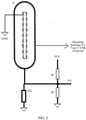
- FIG. 1 is a circuit diagram of a first Type C USB interface according to an embodiment of this application.
- FIG. 1 shows a Type C USB interface J1 of an electronic device.
- a level of the shielding housing of J1 is V0.
- the level of the shielding housing of J1 of the electronic device is a low level because a shielding housing of a Type C USB interface of the external device is connected to the ground of the electronic device and is connected to the shielding housing of J1 of the electronic device.
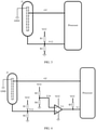
- FIG. 2 is an equivalent circuit diagram in which there is liquid or stains in a Type C USB interface according to an embodiment of this application.
- whether an external device is plugged into the Type C USB interface of the electronic device, whether the external device is unplugged from the Type C USB interface of the electronic device, and whether there is liquid or sundries in the Type C USB interface of the electronic device may be determined by obtaining the level of the shielding housing of the Type C USB interface J1 of the electronic device.
- a pulse signal of a CC pin of the Type C USB interface is disabled; or when it is obtained that the external device is connected to the Type C USB interface of the electronic device, a pulse signal of a CC pin of the Type C USB interface is enabled, to obtain a type of the external device. Therefore, problems of terminal power waste and security risks (such as short circuit and corrosion caused by liquid in the interface) caused by real-time charging of the CC pin of the Type C USB interface are effectively alleviated.
- FIG. 3 is a circuit diagram of a second Type C USB interface according to an embodiment of this application.
- a processor identifies a level V12 of a shielding housing of J1, and controls a signal of a CC pin of a Type C USB interface of an electronic device.
- the processor When the processor identifies that a level value of V12 is less than a first preset threshold, it is determined that an external device is plugged into the Type C USB interface J1 of the electronic device. When it is determined that the external device is plugged into the Type C USB interface J1 of the electronic device, the processor controls to output the signal to the CC pin of J1, to obtain a type of the plugged external device. Optionally, when it is determined that the external device is plugged into the Type C USB interface J1 of the electronic device, text, figures, or audio may be output to inform a user.
- the processor When the processor identifies that the level value of V12 is greater than a second preset threshold and less than a third preset threshold, for example, the level V12 is V0, it is determined that no external device is plugged into the Type C USB interface J1 of the electronic device or that the external device is unplugged from the Type C USB interface J1 of the electronic device. When it is determined that no external device is plugged into the Type C USB interface J1 of the electronic device or that the external device is unplugged from the Type C USB interface J1 of the electronic device, the processor stops outputting the signal to the CC pin of J1. Optionally, when it is determined that the external device is unplugged from the Type C USB interface J1 of the electronic device, text, figures, or audio may be output to inform a user.
- the processor When the processor identifies that the level value of V12 is greater than a first preset threshold and less than a second preset threshold, it is determined that there is liquid or sundries in J1. Because a difference between conductivity capabilities of different liquid or impurities indicates different resistance values of R0, different liquid or impurities correspond to different impedance R0. Therefore, the shielding housing of J1 has different levels. Further, N threshold ranges corresponding to types of the liquid or the sundries may be set between the first preset threshold and the second preset threshold. The type of the liquid or the sundries is determined based on a preset threshold range in which the obtained level falls. Optionally, when it is determined that there is liquid or sundries in the Type C USB interface J1 of the electronic device, text, figures, or audio may be output to inform a user.
- FIG. 4 is a circuit diagram of a third Type C USB interface according to an embodiment of this application.
- FIG. 4 shows an implementation in which a processor determines whether an external device is plugged into J1.
- An electronic device includes a comparator U1, divided voltages R1, R2, R3, and R4, a voltage Vcc, a processor, and an interface J1.
- a shielding housing of J1 is disconnected from the ground of the electronic device and is connected to bleeder resistance R1 and R2.
- a level of the shielding housing of J1 is a level Vcc ⁇ R2/(R1+R2), where the level is divided by R2 and R1.
- a negative input end of the comparator U1 is connected to the divided voltages R3 and R4, and the voltage Vcc is divided by R3 and R4. Therefore, a voltage value V34 of the negative input end of the comparator U1 is a voltage value Vcc ⁇ R4/(R3+R4), where the voltage value is obtained through division on R4.
- a positive input end of the comparator U1 is connected to the shielding housing of the interface of a terminal.
- the comparator U1 When a voltage value V12 of the shielding housing of J1 is greater than V34, the comparator U1 outputs a high level, indicating that the external device is unplugged from the interface J1 or that no external device is plugged into J1; or when V12 is less than V34, the comparator U1 outputs a low level, indicating that the external device is plugged into the interface J1.
- the processor may determine, based on the high/low level output by the comparator U1, whether the external device is plugged into J1.
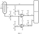
- FIG. 5 is a circuit diagram of a fourth Type C USB interface according to an embodiment of this application.
- FIG. 5 shows another implementation in which a processor determines whether an external device is plugged into J1.
- An electronic device includes comparators U1 and U2, divided voltages R1, R2, R3, R4, R7 and R8, a voltage Vcc, a processor, and an interface J1.
- a shielding housing of J1 is disconnected from the ground of the electronic device and is connected to bleeder resistance R1 and R2.
- a level of the shielding housing of J1 is a level Vcc ⁇ R2/(R1+R2), where the level is divided by R2 and R1.
- Whether the external device is plugged into or unplugged from the interface J1 and whether there is liquid or stains in the interface J1 may be determined by using the comparators U1 and U2.
- a negative input end of the comparator U1 is connected to the divided voltages R3 and R4, and the voltage Vcc is divided by R3 and R4. Therefore, a voltage value V34 of the negative input end of the comparator U1 is a voltage value Vcc ⁇ R4/(R3+R4), where the voltage value is obtained through division on R4.
- a positive input end of the comparator U1 is connected to the shielding housing of the interface J1.
- a negative input end of the comparator U2 is connected to the shielding housing of the interface J1.
- a positive input end of the comparator U2 is connected to the divided voltages R7 and R8, and the voltage Vcc is divided by R7 and R8.
- a voltage value V78 of the positive input end of the comparator U2 is a voltage value Vcc ⁇ R8/(R7+R8), where the voltage value is obtained through division on R8.
- R1, R2, R3, R4, R7 and R8 are selected, so that the voltage of the shielding housing of J1 satisfies: V12>V34 and V12>V78 when no external device is plugged into J1. That is, V1 output by the comparator U1 to the processor is a high level, and V2 output by the comparator U2 to the processor is a low level.
- the processor may determine, based on the level states of V1 and V2, that no external device is plugged into J1 or that the external device is unplugged from J1 in this case.
- the voltage of the shielding housing of the J1 satisfies: V12 ⁇ V78 and V12 ⁇ V34. That is, V1 output by the comparator U1 to the processor is a low level, and V2 output by the comparator U2 to the processor is a high level.
- the processor may determine, based on the level states of V1 and V2, that the external device is plugged into J1 in this case.
- the voltage of the shielding housing of J1 satisfies: V34 ⁇ V12 ⁇ V78. That is, V1 output by the comparator U1 to the processor is a high level, and V2 output by the comparator U2 to the processor is a high level.
- the processor may determine, based on the level states of V1 and V2, that the external device is plugged into J1 in this case.
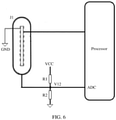
- FIG. 6 is a circuit diagram of a fifth Type C USB interface according to an embodiment of this application.
- FIG. 6 shows still another implementation in which a processor determines whether an external device is plugged into J1.
- An electronic device includes divided voltages R1 and R2, a voltage Vcc, a processor, and an interface J1.
- a shielding housing of J1 is disconnected from the ground of the electronic device and is connected to bleeder resistance R1 and R2.
- a level V12 of the shielding housing of J1 is a level Vcc ⁇ R2/(R1+R2), where the level is divided by R2 and R1.
- the level V12 of the shielding housing of J1 approaches 0, and when there is liquid or stains in the shielding housing of the J1, V12 is between 0 and Vcc ⁇ R2/(R1+R2).
- the processor may determine, by identifying the level of the shielding housing of J1 and comparing the level with a preset threshold, whether the external device is plugged into or unplugged from the interface J1 and whether there is liquid or stains in J1.
- FIG. 7 is a circuit diagram of a sixth Type C USB interface according to an embodiment of this application.
- a processor may be directly connected to a CC pin of an interface J1, so that the processor stops outputting a pulse signal to the CC pin of a Type C USB interface when obtaining that no external device is connected to the Type C USB interface of an electronic device or that the external device is unplugged from the Type C USB interface of the electronic device.
- a processor may be connected to a CC pin of an interface J1 by using a power delivery (power delivery, PD) module.
- the processor controls, when obtaining that no external device is connected to the Type C USB interface of an electronic device or that the external device is unplugged from the Type C USB interface of the electronic device, the PD module to stop outputting a pulse signal to the CC pin of a Type C USB interface.
- a processor may be directly connected to a CC pin of an interface J1, so that the processor outputs a pulse signal to the CC pin of a Type C USB interface when determining that an external device is plugged into the interface J1.
- a processor may be connected to a CC pin of an interface J1 by using a power delivery (power delivery, PD) module.
- the processor controls, when determining that an external device is plugged into the interface J1, the PD module to output a pulse signal to the CC pin of a Type C USB interface.
- the processor may be directly connected to the Type C USB interface, as shown in FIG. 3 to FIG. 6 , or may be connected to the Type C USB interface by using the power delivery (power delivery, PD) module, as shown in FIG. 7 .
- the manner in FIG. 7 in which the processor is connected to the Type C USB interface is applicable to all implementations in the embodiments of this application.
- the manner in FIG. 3 to FIG. 5 in which the processor is directly connected to the Type C USB interface is changed to the manner in which the processor is connected to the Type C USB interface by using the PD module. Details are not described herein again.
- FIG. 8 is a flowchart of a method for controlling a Type C USB interface according to an embodiment of this application.
- the embodiments of this application further provide an interface obtaining method, applied to the electronic device provided in the embodiments of this application.
- the method includes the following steps.
- S1010 Obtain a voltage level of a shielding housing of a Type C USB interface of an electronic device.
- the level may be obtained in a plurality of manners.
- an ADC module is connected to the shielding housing, to obtain the level.
- a specific obtaining manner is not specifically limited in this embodiment.
- the obtained level is less than a first voltage threshold
- S1011 Determine a connection status of the Type C USB interface of the electronic device based on the obtained level.
- Step S1011 specifically includes S102, S103, and S108; or S104, S105, and S108; or S106, S107, and S108.
- S102 Determine that an external device is plugged into the Type C USB interface of the electronic device, where when the obtained level is less than a first voltage threshold, it is determined that the external device is plugged into the Type C USB interface of the electronic device.
- S103 Enable a CC signal of the Type C USB interface, to detect a type of the plugged external device.
- a processor may output the CC signal to the Type C USB interface, or may control a PD module to output the CC signal to the Type C USB interface.
- a processor may output the CC signal to the Type C USB interface, or may control a PD module to output the CC signal to the Type C USB interface.
- the prompt information is used to inform a user that the external device is plugged into the electronic device, or used to inform a user of a device type of the plugged electronic device.
- the prompt information may be text, figures, audio, vibration, or the like.
- S 104 Determine that an external device is unplugged from the Type C USB interface of the electronic device, where when the obtained level is greater than a second voltage threshold and less than a third voltage threshold, it is determined that the external device is unplugged from the Type C USB interface of the electronic device.
- S 105 Disable the CC signal of the Type C USB interface.
- the processor may stop outputting the CC signal to the Type C USB interface, or may control the PD module to stop outputting the CC signal to the Type C USB interface.
- the processor may stop outputting the CC signal to the Type C USB interface, or may control the PD module to stop outputting the CC signal to the Type C USB interface.
- the prompt information is used to inform a user that the external device is unplugged from the electronic device.
- the prompt information may be text, figures, audio, vibration, or the like.
- S106 Determine that there is liquid or stains in the Type C USB interface of the electronic device, where when the obtained level is greater than a first voltage threshold and less than a second voltage threshold, it is determined that there is liquid or stains in the Type C USB interface of the electronic device.
- a type of the liquid or the stains may further be determined based on a range that is between the first voltage threshold and the second voltage threshold and in which the obtained level falls.
- S 107 Disable the CC signal of the Type C USB interface, where when it is determined that there is liquid or stains in the Type C USB interface of the electronic device, the CC signal of the Type C USB interface is disabled, to reduce corrosion on the interface caused by the liquid or the stains.
- the prompt information is used to inform a user that there is liquid or stains in the Type C USB interface, to inform a user to clean the interface in a timely manner.
- a type of the prompt information used to inform the user that there is liquid or stains is optional.
- the prompt information may be text, figures, audio, vibration, or the like.
- the level of the shielding housing of the Type C USB interface of the electronic device is obtained; whether the external device is plugged into or unplugged from the Type C USB interface and whether there is liquid or stains in the Type C USB interface are determined based on the obtained level; when it is determined that the external device is plugged into the Type C USB interface of the electronic device, the CC signal of the Type C USB interface is enabled; and when it is determined that the external device is unplugged from the Type C USB interface of the electronic device or that there is liquid or stains in the Type C USB interface of the electronic device, the CC signal of the Type C USB interface is disabled. Therefore, problems of terminal power waste and security risks (such as short circuit and corrosion caused by the liquid in the interface) caused by real-time charging of the CC pin of the Type C USB interface are effectively alleviated.
- the terminal includes corresponding hardware structures and/or software modules for performing the functions.
- a person of ordinary skill in the art should easily be aware that, in combination with units and algorithms steps of the examples described in the embodiments disclosed in this specification, this application may be implemented by hardware or a combination of hardware and computer software. Whether a function is performed by hardware or hardware driven by computer software depends on particular applications and design constraints of the technical solutions. A person skilled in the art may use different methods to implement the described functions for each particular application, but it should not be considered that the implementation goes beyond the scope of this application.
- functional unit division may be performed for the terminal according to the foregoing method examples.
- the functional unit division may be performed corresponding to the functions, or two or more functions may be integrated in one processing module.
- the integrated unit may be implemented in a form of hardware, or may be implemented in a form of a software functional unit.
- unit division is exemplary, and is merely a logical function division. In an actual implementation, another division manner may be used.
- FIG. 9 is a schematic structural diagram of an electronic device according to an embodiment of the present invention.
- the electronic device specifically includes the following units:
- the output module is further configured to output prompt information when it is determined that the external device is unplugged from the Type C USB interface of the electronic device.
- the prompt information is used to inform a user that the external device is unplugged from the electronic device.
- the prompt information may be text, figures, audio, vibration, or the like.
- the output module is further configured to output prompt information when it is determined that there is liquid or stains in the Type C USB interface of the electronic device.
- the prompt information is used to inform a user that there is liquid or stains in the Type C USB interface, to inform the user to clean the interface in a timely manner.
- a type of the prompt information used to inform the user that there is liquid or stains is optional.
- the prompt information may be text, figures, audio, vibration, or the like.
- FIG. 10 is a schematic structural diagram of another electronic device according to an embodiment of the present invention.
- the device includes a processor 1010, a memory 1020, a Type C USB interface 1050, and a display 1060.
- the processor 1010, the memory 1020, the Type C USB interface 1050, and the display 1060 are connected to each other by using a bus.
- the memory 1020 is configured to store computer executable program code, and the program code includes an instruction.
- the processor 1010 runs the instruction stored in the memory 1020, to implement various functional applications and data processing of the electronic device.
- the memory 1020 may mainly include a program storage area and a data storage area.
- the program storage area may store an operating system, an application program required by at least one function (for example, a prompt information displaying function, a sound playing function, and an image playing function), or the like.
- the data storage area may store data (for example, audio data and a phone book) created according to use of the electronic device.
- the memory 120 may include a high-speed random access memory, and may further include a nonvolatile memory such as at least one disk storage device, a flash storage device, or another volatile solid-state storage device.
- the processor 1010 is a control center of the electronic device, and is connected to various parts of the entire mobile phone by using various interfaces and lines. By running or executing a software program and/or a module stored in the memory 1020, and invoking data stored in the memory 1020, various functions and data processing of the electronic device are performed, thereby implementing overall monitoring on the electronic device.
- the processor 1010 may include one or more processing units.
- the processor 1010 may integrate an application processor, a modem processor, a baseband module, a power management chip, a memory, a coder/decoder, and the like.
- the application processor mainly processes an operating system, a user interface, an application program, and the like.
- the modem processor mainly processes wireless communication.
- the modem processor may either not be integrated into the processor 1010.
- the internet protocol, the wireless local area network protocol (for example, IEEE 702.11), 3G communication protocol, 4G communication protocol, 5G communication protocol, or the like may be implemented by using the processor 1010 and the memory 1020.
- the processor 1010 in this embodiment of this application is configured to obtain a level of a shielding housing of a Type C USB interface 1050 of the electronic device; determine, based on the obtained level, whether an external device is plugged into or unplugged from the Type C USB interface of the electronic device and whether there is liquid or stains in the Type C USB interface of the electronic device; and enable a CC signal of the Type C USB interface when it is determined that the external device is plugged into the Type C USB interface of the electronic device; and is further configured to disable the CC signal of the Type C USB interface when it is determined that the external device is unplugged from the Type C USB interface of the electronic device or that there is liquid or stains in the Type C USB interface of the electronic device.
- the processor is further configured to output prompt information when it is determined that the external device is plugged into the Type C USB interface of the electronic device.
- the prompt information is used to inform a user that the external device is plugged into the electronic device, or used to inform a user of a device type of the plugged electronic device.
- the prompt information may be text, figures, audio, vibration, or the like.
- the processor is further configured to output prompt information when it is determined that the external device is unplugged from the Type C USB interface of the electronic device.
- the prompt information is used to inform a user that the external device is unplugged from the electronic device.
- the prompt information may be text, figures, audio, vibration, or the like.
- the processor is further configured to output prompt information when it is determined that there is liquid or stains in the Type C USB interface of the electronic device.
- the prompt information is used to inform a user that there is liquid or stains in the Type C USB interface, to inform a user to clean the interface in a timely manner.
- a type of the prompt information used to inform the user that there is liquid or stains is optional.
- the prompt information may be text, figures, audio, vibration, or the like.
- the foregoing prompt information may be output by the display screen 1060 of the electronic device, or may be output by an audio device, such as a speaker (not shown).
- the Type C USB interface may be a charging interface or a headset jack.
- the external device connected to the Type C USB interface of the electronic device may be a charger or a headset.
- the processor invokes the instruction stored in the memory to implement the solution of this embodiment of this application. Therefore, for a specific implementation, refer to the foregoing embodiments of this application. Repeated descriptions are not provided again.
- the level may represent a power supply, or may represent a level value of a power supply; and R may represent a resistance device in a circuit, or may represent a resistance value of resistance.
- the integrated unit When the integrated unit is implemented in the form of a software functional unit and sold or used as an independent product, the integrated unit may be stored in a computer-readable storage medium. Based on such an understanding, all or some of the technical solutions of this application may be implemented in a form of a software product.
- the software product is stored in a storage medium, and includes instructions for instructing a computer device (which may be a personal computer, a server, a network device, or the like) to perform all or some of the steps of the methods described in the embodiments of this application.
- the foregoing storage medium includes various media that can store program code, such as a flash drive, a removable hard disk, a read-only memory (English: read-only memory, ROM), a random access memory (English: random access memory, RAM), a magnetic disk, or an optical disc.
- program code such as a flash drive, a removable hard disk, a read-only memory (English: read-only memory, ROM), a random access memory (English: random access memory, RAM), a magnetic disk, or an optical disc.
Landscapes
- Engineering & Computer Science (AREA)
- Theoretical Computer Science (AREA)
- General Engineering & Computer Science (AREA)
- Physics & Mathematics (AREA)
- General Physics & Mathematics (AREA)
- Computer Hardware Design (AREA)
- Power Sources (AREA)
- Microelectronics & Electronic Packaging (AREA)
Claims (11)
- Dispositif électronique, dans lequel le dispositif électronique comprend une interface USB de type C (J1, 1050), et l'interface USB de type C (J1, 1050) a un boîtier de blindage ; et le dispositif électronique comprend en outre un processeur (1010), dans lequelle processeur (1010) est connecté à l'interface USB de type C (J1, 1050) ;l'interface USB de type C (J1, 1050) est configurée pour se connecter à un dispositif externe ;le boîtier de blindage de l'interface USB de type C (J1, 1050) est déconnecté d'un signal de mise à la masse du dispositif électronique et est connecté à une première résistance (R1) et une seconde résistance (R2), la première résistance (R1) et la seconde résistance (R2) sont configurées pour diviser une tension (Vcc) afin de générer une tension divisée (V0) et pour appliquer la tension divisée (V0) au boîtier de blindage de l'interface USB de type C (J1, 1050) ;lorsqu'aucun dispositif externe n'est connecté à l'interface USB de type C (J1, 1050), un niveau de tension du boîtier de blindage de l'interface USB de type C (J1, 1050) est un premier niveau de tension, le premier niveau de tension étant supérieur à 0 ;lorsque le dispositif externe est connecté à l'interface USB de type C (J1, 1050), le processeur (1010) émet un signal vers une broche CC de l'interface USB de type C (J1, 1050) ; etlorsqu'aucun dispositif externe n'est connecté à l'interface USB de type C (J1, 1050), le processeur (1010) arrête d'émettre le signal vers la broche CC de l'interface USB de type C (J1, 1050) ;le dispositif électronique comprend en outre un premier comparateur (U1) ; une première extrémité d'entrée positive du premier comparateur (U1) est connectée au boîtier de blindage de l'interface USB de type C (J1, 1050) ; une première extrémité d'entrée négative du premier comparateur (U1) est connectée à une première tension de référence ; une première extrémité de sortie du premier comparateur (U1) est connectée au processeur (1010) ; le premier comparateur (U1) est configuré pour comparer un niveau de tension de la première extrémité d'entrée positive avec un niveau de tension de la première extrémité d'entrée négative et émettre un premier signal de comparaison au processeur (1010) ; et le processeur (1010) est configuré pour déterminer, sur la base du premier signal de comparaison, que le dispositif externe est débranché de l'interface USB de type C (J1, 1050) et/ou que le dispositif externe est connecté à l'interface USB de type C (J1, 1050) ; oule processeur (1010) comprend un module de détection ADC, et le module de détection ADC est connecté au boîtier de blindage de l'interface USB de type C (J1, 1050) ; le module de détection ADC est configuré pour détecter le niveau de tension du boîtier de blindage de l'interface USB de type C (J1, 1050) ; et le processeur (1010) est configuré pour déterminer, sur la base du niveau de tension détecté par le module de détection ADC, que le dispositif externe est débranché de l'interface USB de type C (J1, 1050), et/ou que le dispositif externe est connecté à l'interface USB de type C (J1, 1050), et/ou qu'il y a du liquide dans l'interface USB de type C.
- Dispositif électronique selon la revendication 1, dans lequel le dispositif électronique comprend en outre un module de distribution d'énergie, PD, le processeur (1010) étant connecté à l'interface USB de type C (J1, 1050) à l'aide du module PD ; et le processeur (1010) est spécifiquement configuré pour :lorsque le dispositif externe est connecté à l'interface USB de type C (J1, 1050), commander le module PD pour émettre le signal vers la broche CC de l'interface USB de type C (J1, 1050) ; etlorsqu'aucun dispositif externe n'est connecté à l'interface USB de type C (J1, 1050), commander le module PD pour arrêter d'émettre le signal vers la broche CC de l'interface USB de type C (J1, 1050).
- Dispositif électronique selon la revendication 1 ou 2, dans lequel le processeur (1010) est en outre configuré pour :émettre les premières informations d'invite lorsque le dispositif externe est débranché de l'interface USB de type C (J1, 1050), les premières informations d'invite étant utilisées pour informer que le dispositif externe est débranché de l'interface USB de type C (J1, 1050) ; et/ouémettre des deuxièmes informations d'invite lorsque le dispositif externe est connecté à l'interface USB de type C (J1, 1050), les deuxièmes informations d'invite étant utilisées pour indiquer que le dispositif externe est connecté à l'interface USB de type C (J1, 1050).
- Dispositif électronique selon l'une quelconque des revendications 1 à 3, dans lequel le processeur (1010) est en outre configuré pour arrêter d'émettre le signal vers la broche CC de l'interface USB de type C (J1, 1050) lorsqu'il y a du liquide ou des taches dans l'interface USB de type C (J1, 1050).
- Dispositif électronique selon la revendication 4, dans lequel le processeur (1010) est en outre configuré pour émettre des troisièmes informations d'invite, et les troisièmes informations d'invite sont utilisées pour informer qu'il y a du liquide ou des taches dans l'interface USB de type C (J1, 1050).
- Dispositif électronique selon l'une quelconque des revendications 1 à 5, le dispositif électronique comprenant en outre un second comparateur (U2) ;une seconde extrémité d'entrée négative du second comparateur (U2) est connectée au boîtier de blindage de l'interface USB de type C (J1, 1050) ;une seconde extrémité d'entrée positive du second comparateur (U2) est connectée à une seconde tension de référence ;une seconde extrémité de sortie du second comparateur (U2) est connectée au processeur (1010) ;le second comparateur (U2) est configuré pour comparer un niveau de tension de la seconde extrémité d'entrée positive avec un niveau de tension de la seconde extrémité d'entrée négative et émettre un second signal de comparaison vers le processeur (1010) ; etle processeur (1010) est configuré pour déterminer, sur la base du premier signal de comparaison et du second signal de comparaison, que le dispositif externe est débranché de l'interface USB de type C (J1, 1050), et/ou que le dispositif externe est connecté à l'interface USB de type C (J1, 1050) et/ou qu'il y a du liquide ou des taches dans l'interface USB de type C (J1, 1050).
- Procédé de commande d'une interface USB de type C (J1, 1050), appliqué au dispositif électronique selon les revendications 1 à 6, dans lequel le procédé comprend :l'arrêt (S105) de la sortie d'un signal à une broche CC de l'interface USB de type C (J1, 1050) lorsqu'aucun dispositif externe n'est connecté à l'interface USB de type C (J1, 1050) ;le procédé comprenant en outre :l'obtention (S1010) d'un niveau de tension d'un boîtier de blindage de l'interface USB de type C (J1, 1050) ; etla détermination (S102, S104, S106), sur la base du niveau de tension du boîtier de blindage de l'interface USB de type C (J1, 1050), du fait qu'un dispositif externe est débranché de l'interface USB de type C (J1, 1050), ou du fait que le dispositif externe est connecté à l'interface USB de type C (J1, 1050), ou du fait qu'il y a du liquide ou des taches dans l'interface USB de type C (J1, 1050).
- Procédé selon la revendication 7, dans lequel le procédé comprend en outre : l'émission (S103) du signal vers la broche CC de l'interface USB de type C (J1, 1050) lorsque le dispositif externe est branché dans l'interface USB de type C (J1, 1050).
- Procédé selon la revendication 7 ou 8, le procédé comprenant en outre :la sortie (S108) des premières informations d'invite lorsque le dispositif externe est débranché de l'interface USB de type C (J1, 1050), les premières informations d'invite étant utilisées pour indiquer que le dispositif externe est débranché de l'interface USB de type C (J1, 1050) ; etla sortie (S108) des deuxièmes informations d'invite lorsque le dispositif externe est connecté à l'interface USB de type C (J1, 1050), les deuxièmes informations d'invite étant utilisées pour indiquer que le dispositif externe est connecté à l'interface USB de type C (J1, 1050).
- Procédé selon l'une quelconque des revendications 7 à 9, dans lequel le procédé comprend en outre : l'arrêt (S107) de la sortie du signal vers la broche CC de l'interface USB de type C (J1, 1050) lorsqu'il y a du liquide ou des taches dans le type C Interface USB (J1, 1050).
- Procédé selon l'une quelconque des revendications 7 à 10, dans lequel le procédé comprend en outre la sortie (S107) de troisièmes informations d'invite, et les troisièmes informations d'invite sont utilisées pour informer qu'il y a du liquide ou des taches dans l'interface USB de type C (J1, 1050).
Applications Claiming Priority (1)
| Application Number | Priority Date | Filing Date | Title |
|---|---|---|---|
| PCT/CN2017/105135 WO2019061538A1 (fr) | 2017-09-30 | 2017-09-30 | Dispositif électronique ayant une interface usb de type c, procédé de commande pour interface usb de type c, et support d'informations |
Publications (3)
| Publication Number | Publication Date |
|---|---|
| EP3674904A1 EP3674904A1 (fr) | 2020-07-01 |
| EP3674904A4 EP3674904A4 (fr) | 2020-08-19 |
| EP3674904B1 true EP3674904B1 (fr) | 2022-02-23 |
Family
ID=65902324
Family Applications (1)
| Application Number | Title | Priority Date | Filing Date |
|---|---|---|---|
| EP17926441.1A Active EP3674904B1 (fr) | 2017-09-30 | 2017-09-30 | Dispositif électronique ayant une interface usb de type c, procédé de commande pour interface usb de type c, et support d'informations |
Country Status (4)
| Country | Link |
|---|---|
| US (1) | US11074212B2 (fr) |
| EP (1) | EP3674904B1 (fr) |
| CN (1) | CN110366721B (fr) |
| WO (1) | WO2019061538A1 (fr) |
Families Citing this family (6)
| Publication number | Priority date | Publication date | Assignee | Title |
|---|---|---|---|---|
| KR102406959B1 (ko) * | 2017-11-28 | 2022-06-13 | 삼성전자주식회사 | 커넥터를 포함하는 전자 장치 및 전자 장치에서의 전력 송수신을 제어하는 방법 |
| RU2764146C1 (ru) * | 2018-07-24 | 2022-01-13 | Хонор Дивайс Ко., Лтд. | Терминал и способ защиты от коррозии интерфейса type c |
| CN111949107B (zh) * | 2019-05-15 | 2023-11-07 | 北京小米移动软件有限公司 | 控制包括USB Type-C接口的电子设备的方法和装置、电子设备 |
| CN112187252A (zh) * | 2020-10-12 | 2021-01-05 | 深圳市道通科技股份有限公司 | 接口识别电路、方法、设备和电子设备 |
| CN114236240B (zh) * | 2022-02-25 | 2023-10-20 | 荣耀终端有限公司 | 进液检测电路和电子设备 |
| CN114624632B (zh) * | 2022-05-17 | 2022-09-30 | 陕西天视致远航空技术有限公司 | Usb端口插拔检测系统、方法、电子设备及存储介质 |
Family Cites Families (15)
| Publication number | Priority date | Publication date | Assignee | Title |
|---|---|---|---|---|
| US9146888B2 (en) * | 2012-07-05 | 2015-09-29 | Apple Inc. | Techniques for monitoring contacts in a connector |
| US9030208B2 (en) | 2013-02-07 | 2015-05-12 | Apple Inc. | Using pulsed DC to detect connector mating and unmating |
| CN104218350B (zh) | 2014-07-30 | 2020-11-13 | 连展科技电子(昆山)有限公司 | 插头电连接器 |
| CN104268110B (zh) * | 2014-09-15 | 2018-10-12 | 联想(北京)有限公司 | 一种设备识别方法、处理器和设备识别系统 |
| CN106291210B (zh) | 2015-05-22 | 2020-05-05 | 快捷半导体(苏州)有限公司 | Usb接口检测器、检测方法、usb连接器及电子设备 |
| US9400546B1 (en) * | 2015-06-19 | 2016-07-26 | Cypress Semiconductor Corporation | Low-power implementation of Type-C connector subsystem |
| US10014637B2 (en) | 2015-10-20 | 2018-07-03 | Sony Mobile Communications Inc. | Connector receptacle interfacing circuit and method of operation |
| US11277015B2 (en) * | 2016-01-05 | 2022-03-15 | Semiconductor Components Industries, Llc | USB Type-C connector with shorted differential data contacts |
| CN105630724B (zh) * | 2016-01-27 | 2017-03-15 | 深圳慧能泰半导体科技有限公司 | 一种USB Type‑C系统控制电路 |
| CN105656162B (zh) | 2016-03-17 | 2018-06-08 | 深圳市乐得瑞科技有限公司 | 基于usb pd协议的快速充电系统及方法 |
| CN105955912B (zh) * | 2016-05-16 | 2019-01-25 | 芯海科技(深圳)股份有限公司 | 一种用于usb type-c接口的设备检测方法 |
| CN106095715B (zh) * | 2016-06-17 | 2019-04-16 | 芯海科技(深圳)股份有限公司 | 一种Type-C自动识别电路及识别方法 |
| CN106020176B (zh) * | 2016-07-29 | 2018-11-02 | 珠海智融科技有限公司 | 一种cc逻辑控制芯片低功耗连接检测方法及结构 |
| CN106802875A (zh) * | 2017-01-13 | 2017-06-06 | 珠海市魅族科技有限公司 | 电子设备 |
| CN106844265B (zh) | 2017-02-06 | 2018-10-19 | 维沃移动通信有限公司 | 一种通用串行总线usb接口的控制方法及移动终端 |
-
2017
- 2017-09-30 US US16/650,340 patent/US11074212B2/en active Active
- 2017-09-30 EP EP17926441.1A patent/EP3674904B1/fr active Active
- 2017-09-30 WO PCT/CN2017/105135 patent/WO2019061538A1/fr not_active Ceased
- 2017-09-30 CN CN201780085805.2A patent/CN110366721B/zh active Active
Also Published As
| Publication number | Publication date |
|---|---|
| CN110366721A (zh) | 2019-10-22 |
| CN110366721B (zh) | 2021-06-15 |
| US20200311010A1 (en) | 2020-10-01 |
| US11074212B2 (en) | 2021-07-27 |
| EP3674904A1 (fr) | 2020-07-01 |
| EP3674904A4 (fr) | 2020-08-19 |
| WO2019061538A1 (fr) | 2019-04-04 |
Similar Documents
| Publication | Publication Date | Title |
|---|---|---|
| EP3674904B1 (fr) | Dispositif électronique ayant une interface usb de type c, procédé de commande pour interface usb de type c, et support d'informations | |
| CA2969011C (fr) | Procede et appareil de protection de charge | |
| JP7121865B2 (ja) | 逆方向充電装置、逆方向充電電流調整方法及び装置 | |
| US20190260211A1 (en) | Power adapter, terminal, and method for processing impedance anomalies in charging loop | |
| KR102439078B1 (ko) | 전자 장치 및 그의 충전 제어 방법 | |
| JP5005845B2 (ja) | 電子機器 | |
| KR20160100973A (ko) | Usb 접속으로 전자 디바이스를 충전하기 위한 방법 및 장치 | |
| KR20130122266A (ko) | 호스트모드에서 충전동작을 수행하는 시스템, 장치 및 방법 | |
| CN106502368B (zh) | 一种移动终端的otg外设控制方法及系统 | |
| CN106786960A (zh) | 充电控制方法、装置及终端 | |
| US10411466B2 (en) | Apparatus and method for a mobile router to receive power from a plurality of power supplies | |
| CN105576753A (zh) | 一种信息处理方法及电子设备 | |
| US20130244455A1 (en) | Processing device and processing system | |
| CN105958562A (zh) | 用于电子设备的充电保护方法、装置及电子设备 | |
| CN105204954A (zh) | 一种处理死机状态的方法和终端 | |
| US10742057B2 (en) | Self-loop detection method and apparatus for charging device | |
| CN105098854B (zh) | 充电方法与电子装置 | |
| EP3070961B1 (fr) | Circuit pour détecter une action de pression de bouton d'un écouteur, terminal et écouteur | |
| CN116979625A (zh) | 充电保护电路、充电保护方法、终端设备及存储介质 | |
| CN110120695B (zh) | 一种充电方法及终端设备 | |
| CN106972568A (zh) | 充电检测电路、方法及电子设备 | |
| EP2645202B1 (fr) | Procédé d'alimentation d'un terminal de réseau sans fil et terminal de réseau sans fil | |
| US20130165096A1 (en) | Incoming call forwarding method and communication device having incoming call forwarding function | |
| CN106787648B (zh) | 一种保护移动终端开机的方法及系统 | |
| CN110989812B (zh) | 加密设备、系统及加密设备控制方法 |
Legal Events
| Date | Code | Title | Description |
|---|---|---|---|
| STAA | Information on the status of an ep patent application or granted ep patent |
Free format text: STATUS: THE INTERNATIONAL PUBLICATION HAS BEEN MADE |
|
| PUAI | Public reference made under article 153(3) epc to a published international application that has entered the european phase |
Free format text: ORIGINAL CODE: 0009012 |
|
| STAA | Information on the status of an ep patent application or granted ep patent |
Free format text: STATUS: REQUEST FOR EXAMINATION WAS MADE |
|
| 17P | Request for examination filed |
Effective date: 20200324 |
|
| AK | Designated contracting states |
Kind code of ref document: A1 Designated state(s): AL AT BE BG CH CY CZ DE DK EE ES FI FR GB GR HR HU IE IS IT LI LT LU LV MC MK MT NL NO PL PT RO RS SE SI SK SM TR |
|
| AX | Request for extension of the european patent |
Extension state: BA ME |
|
| A4 | Supplementary search report drawn up and despatched |
Effective date: 20200721 |
|
| RIC1 | Information provided on ipc code assigned before grant |
Ipc: G06F 13/40 20060101AFI20200715BHEP Ipc: G06F 13/42 20060101ALI20200715BHEP |
|
| DAV | Request for validation of the european patent (deleted) | ||
| DAX | Request for extension of the european patent (deleted) | ||
| GRAP | Despatch of communication of intention to grant a patent |
Free format text: ORIGINAL CODE: EPIDOSNIGR1 |
|
| STAA | Information on the status of an ep patent application or granted ep patent |
Free format text: STATUS: GRANT OF PATENT IS INTENDED |
|
| GRAJ | Information related to disapproval of communication of intention to grant by the applicant or resumption of examination proceedings by the epo deleted |
Free format text: ORIGINAL CODE: EPIDOSDIGR1 |
|
| GRAP | Despatch of communication of intention to grant a patent |
Free format text: ORIGINAL CODE: EPIDOSNIGR1 |
|
| INTG | Intention to grant announced |
Effective date: 20211013 |
|
| INTG | Intention to grant announced |
Effective date: 20211027 |
|
| GRAS | Grant fee paid |
Free format text: ORIGINAL CODE: EPIDOSNIGR3 |
|
| GRAA | (expected) grant |
Free format text: ORIGINAL CODE: 0009210 |
|
| STAA | Information on the status of an ep patent application or granted ep patent |
Free format text: STATUS: THE PATENT HAS BEEN GRANTED |
|
| AK | Designated contracting states |
Kind code of ref document: B1 Designated state(s): AL AT BE BG CH CY CZ DE DK EE ES FI FR GB GR HR HU IE IS IT LI LT LU LV MC MK MT NL NO PL PT RO RS SE SI SK SM TR |
|
| REG | Reference to a national code |
Ref country code: GB Ref legal event code: FG4D |
|
| REG | Reference to a national code |
Ref country code: CH Ref legal event code: EP |
|
| REG | Reference to a national code |
Ref country code: DE Ref legal event code: R096 Ref document number: 602017053908 Country of ref document: DE |
|
| REG | Reference to a national code |
Ref country code: AT Ref legal event code: REF Ref document number: 1470995 Country of ref document: AT Kind code of ref document: T Effective date: 20220315 |
|
| REG | Reference to a national code |
Ref country code: IE Ref legal event code: FG4D |
|
| REG | Reference to a national code |
Ref country code: LT Ref legal event code: MG9D |
|
| REG | Reference to a national code |
Ref country code: NL Ref legal event code: MP Effective date: 20220223 |
|
| REG | Reference to a national code |
Ref country code: AT Ref legal event code: MK05 Ref document number: 1470995 Country of ref document: AT Kind code of ref document: T Effective date: 20220223 |
|
| PG25 | Lapsed in a contracting state [announced via postgrant information from national office to epo] |
Ref country code: SE Free format text: LAPSE BECAUSE OF FAILURE TO SUBMIT A TRANSLATION OF THE DESCRIPTION OR TO PAY THE FEE WITHIN THE PRESCRIBED TIME-LIMIT Effective date: 20220223 Ref country code: RS Free format text: LAPSE BECAUSE OF FAILURE TO SUBMIT A TRANSLATION OF THE DESCRIPTION OR TO PAY THE FEE WITHIN THE PRESCRIBED TIME-LIMIT Effective date: 20220223 Ref country code: PT Free format text: LAPSE BECAUSE OF FAILURE TO SUBMIT A TRANSLATION OF THE DESCRIPTION OR TO PAY THE FEE WITHIN THE PRESCRIBED TIME-LIMIT Effective date: 20220623 Ref country code: NO Free format text: LAPSE BECAUSE OF FAILURE TO SUBMIT A TRANSLATION OF THE DESCRIPTION OR TO PAY THE FEE WITHIN THE PRESCRIBED TIME-LIMIT Effective date: 20220523 Ref country code: NL Free format text: LAPSE BECAUSE OF FAILURE TO SUBMIT A TRANSLATION OF THE DESCRIPTION OR TO PAY THE FEE WITHIN THE PRESCRIBED TIME-LIMIT Effective date: 20220223 Ref country code: LT Free format text: LAPSE BECAUSE OF FAILURE TO SUBMIT A TRANSLATION OF THE DESCRIPTION OR TO PAY THE FEE WITHIN THE PRESCRIBED TIME-LIMIT Effective date: 20220223 Ref country code: HR Free format text: LAPSE BECAUSE OF FAILURE TO SUBMIT A TRANSLATION OF THE DESCRIPTION OR TO PAY THE FEE WITHIN THE PRESCRIBED TIME-LIMIT Effective date: 20220223 Ref country code: ES Free format text: LAPSE BECAUSE OF FAILURE TO SUBMIT A TRANSLATION OF THE DESCRIPTION OR TO PAY THE FEE WITHIN THE PRESCRIBED TIME-LIMIT Effective date: 20220223 Ref country code: BG Free format text: LAPSE BECAUSE OF FAILURE TO SUBMIT A TRANSLATION OF THE DESCRIPTION OR TO PAY THE FEE WITHIN THE PRESCRIBED TIME-LIMIT Effective date: 20220523 |
|
| PG25 | Lapsed in a contracting state [announced via postgrant information from national office to epo] |
Ref country code: PL Free format text: LAPSE BECAUSE OF FAILURE TO SUBMIT A TRANSLATION OF THE DESCRIPTION OR TO PAY THE FEE WITHIN THE PRESCRIBED TIME-LIMIT Effective date: 20220223 Ref country code: LV Free format text: LAPSE BECAUSE OF FAILURE TO SUBMIT A TRANSLATION OF THE DESCRIPTION OR TO PAY THE FEE WITHIN THE PRESCRIBED TIME-LIMIT Effective date: 20220223 Ref country code: GR Free format text: LAPSE BECAUSE OF FAILURE TO SUBMIT A TRANSLATION OF THE DESCRIPTION OR TO PAY THE FEE WITHIN THE PRESCRIBED TIME-LIMIT Effective date: 20220524 Ref country code: FI Free format text: LAPSE BECAUSE OF FAILURE TO SUBMIT A TRANSLATION OF THE DESCRIPTION OR TO PAY THE FEE WITHIN THE PRESCRIBED TIME-LIMIT Effective date: 20220223 Ref country code: AT Free format text: LAPSE BECAUSE OF FAILURE TO SUBMIT A TRANSLATION OF THE DESCRIPTION OR TO PAY THE FEE WITHIN THE PRESCRIBED TIME-LIMIT Effective date: 20220223 |
|
| PG25 | Lapsed in a contracting state [announced via postgrant information from national office to epo] |
Ref country code: IS Free format text: LAPSE BECAUSE OF FAILURE TO SUBMIT A TRANSLATION OF THE DESCRIPTION OR TO PAY THE FEE WITHIN THE PRESCRIBED TIME-LIMIT Effective date: 20220623 |
|
| PG25 | Lapsed in a contracting state [announced via postgrant information from national office to epo] |
Ref country code: SM Free format text: LAPSE BECAUSE OF FAILURE TO SUBMIT A TRANSLATION OF THE DESCRIPTION OR TO PAY THE FEE WITHIN THE PRESCRIBED TIME-LIMIT Effective date: 20220223 Ref country code: SK Free format text: LAPSE BECAUSE OF FAILURE TO SUBMIT A TRANSLATION OF THE DESCRIPTION OR TO PAY THE FEE WITHIN THE PRESCRIBED TIME-LIMIT Effective date: 20220223 Ref country code: RO Free format text: LAPSE BECAUSE OF FAILURE TO SUBMIT A TRANSLATION OF THE DESCRIPTION OR TO PAY THE FEE WITHIN THE PRESCRIBED TIME-LIMIT Effective date: 20220223 Ref country code: EE Free format text: LAPSE BECAUSE OF FAILURE TO SUBMIT A TRANSLATION OF THE DESCRIPTION OR TO PAY THE FEE WITHIN THE PRESCRIBED TIME-LIMIT Effective date: 20220223 Ref country code: DK Free format text: LAPSE BECAUSE OF FAILURE TO SUBMIT A TRANSLATION OF THE DESCRIPTION OR TO PAY THE FEE WITHIN THE PRESCRIBED TIME-LIMIT Effective date: 20220223 Ref country code: CZ Free format text: LAPSE BECAUSE OF FAILURE TO SUBMIT A TRANSLATION OF THE DESCRIPTION OR TO PAY THE FEE WITHIN THE PRESCRIBED TIME-LIMIT Effective date: 20220223 |
|
| REG | Reference to a national code |
Ref country code: DE Ref legal event code: R097 Ref document number: 602017053908 Country of ref document: DE |
|
| PG25 | Lapsed in a contracting state [announced via postgrant information from national office to epo] |
Ref country code: AL Free format text: LAPSE BECAUSE OF FAILURE TO SUBMIT A TRANSLATION OF THE DESCRIPTION OR TO PAY THE FEE WITHIN THE PRESCRIBED TIME-LIMIT Effective date: 20220223 |
|
| PLBE | No opposition filed within time limit |
Free format text: ORIGINAL CODE: 0009261 |
|
| STAA | Information on the status of an ep patent application or granted ep patent |
Free format text: STATUS: NO OPPOSITION FILED WITHIN TIME LIMIT |
|
| 26N | No opposition filed |
Effective date: 20221124 |
|
| PG25 | Lapsed in a contracting state [announced via postgrant information from national office to epo] |
Ref country code: SI Free format text: LAPSE BECAUSE OF FAILURE TO SUBMIT A TRANSLATION OF THE DESCRIPTION OR TO PAY THE FEE WITHIN THE PRESCRIBED TIME-LIMIT Effective date: 20220223 |
|
| PG25 | Lapsed in a contracting state [announced via postgrant information from national office to epo] |
Ref country code: MC Free format text: LAPSE BECAUSE OF FAILURE TO SUBMIT A TRANSLATION OF THE DESCRIPTION OR TO PAY THE FEE WITHIN THE PRESCRIBED TIME-LIMIT Effective date: 20220223 |
|
| REG | Reference to a national code |
Ref country code: CH Ref legal event code: PL |
|
| REG | Reference to a national code |
Ref country code: BE Ref legal event code: MM Effective date: 20220930 |
|
| PG25 | Lapsed in a contracting state [announced via postgrant information from national office to epo] |
Ref country code: LU Free format text: LAPSE BECAUSE OF NON-PAYMENT OF DUE FEES Effective date: 20220930 |
|
| PG25 | Lapsed in a contracting state [announced via postgrant information from national office to epo] |
Ref country code: LI Free format text: LAPSE BECAUSE OF NON-PAYMENT OF DUE FEES Effective date: 20220930 Ref country code: IT Free format text: LAPSE BECAUSE OF FAILURE TO SUBMIT A TRANSLATION OF THE DESCRIPTION OR TO PAY THE FEE WITHIN THE PRESCRIBED TIME-LIMIT Effective date: 20220223 Ref country code: IE Free format text: LAPSE BECAUSE OF NON-PAYMENT OF DUE FEES Effective date: 20220930 Ref country code: CH Free format text: LAPSE BECAUSE OF NON-PAYMENT OF DUE FEES Effective date: 20220930 |
|
| PG25 | Lapsed in a contracting state [announced via postgrant information from national office to epo] |
Ref country code: BE Free format text: LAPSE BECAUSE OF NON-PAYMENT OF DUE FEES Effective date: 20220930 |
|
| PG25 | Lapsed in a contracting state [announced via postgrant information from national office to epo] |
Ref country code: CY Free format text: LAPSE BECAUSE OF FAILURE TO SUBMIT A TRANSLATION OF THE DESCRIPTION OR TO PAY THE FEE WITHIN THE PRESCRIBED TIME-LIMIT Effective date: 20220223 |
|
| PG25 | Lapsed in a contracting state [announced via postgrant information from national office to epo] |
Ref country code: MK Free format text: LAPSE BECAUSE OF FAILURE TO SUBMIT A TRANSLATION OF THE DESCRIPTION OR TO PAY THE FEE WITHIN THE PRESCRIBED TIME-LIMIT Effective date: 20220223 Ref country code: HU Free format text: LAPSE BECAUSE OF FAILURE TO SUBMIT A TRANSLATION OF THE DESCRIPTION OR TO PAY THE FEE WITHIN THE PRESCRIBED TIME-LIMIT; INVALID AB INITIO Effective date: 20170930 |
|
| PG25 | Lapsed in a contracting state [announced via postgrant information from national office to epo] |
Ref country code: MT Free format text: LAPSE BECAUSE OF FAILURE TO SUBMIT A TRANSLATION OF THE DESCRIPTION OR TO PAY THE FEE WITHIN THE PRESCRIBED TIME-LIMIT Effective date: 20220223 |
|
| PGFP | Annual fee paid to national office [announced via postgrant information from national office to epo] |
Ref country code: DE Payment date: 20250805 Year of fee payment: 9 |
|
| PGFP | Annual fee paid to national office [announced via postgrant information from national office to epo] |
Ref country code: GB Payment date: 20250807 Year of fee payment: 9 |
|
| PGFP | Annual fee paid to national office [announced via postgrant information from national office to epo] |
Ref country code: FR Payment date: 20250808 Year of fee payment: 9 |
|
| PG25 | Lapsed in a contracting state [announced via postgrant information from national office to epo] |
Ref country code: TR Free format text: LAPSE BECAUSE OF FAILURE TO SUBMIT A TRANSLATION OF THE DESCRIPTION OR TO PAY THE FEE WITHIN THE PRESCRIBED TIME-LIMIT Effective date: 20220223 |