EP3675152A1 - Wärmeableitungsvorrichtung - Google Patents
Wärmeableitungsvorrichtung Download PDFInfo
- Publication number
- EP3675152A1 EP3675152A1 EP19217626.1A EP19217626A EP3675152A1 EP 3675152 A1 EP3675152 A1 EP 3675152A1 EP 19217626 A EP19217626 A EP 19217626A EP 3675152 A1 EP3675152 A1 EP 3675152A1
- Authority
- EP
- European Patent Office
- Prior art keywords
- peak portion
- heat
- heat dissipation
- dissipation device
- circle
- Prior art date
- Legal status (The legal status is an assumption and is not a legal conclusion. Google has not performed a legal analysis and makes no representation as to the accuracy of the status listed.)
- Withdrawn
Links
Images


Classifications
-
- F—MECHANICAL ENGINEERING; LIGHTING; HEATING; WEAPONS; BLASTING
- F28—HEAT EXCHANGE IN GENERAL
- F28F—DETAILS OF HEAT-EXCHANGE AND HEAT-TRANSFER APPARATUS, OF GENERAL APPLICATION
- F28F13/00—Arrangements for modifying heat-transfer, e.g. increasing, decreasing
- F28F13/18—Arrangements for modifying heat-transfer, e.g. increasing, decreasing by applying coatings, e.g. radiation-absorbing, radiation-reflecting; by surface treatment, e.g. polishing
-
- H—ELECTRICITY
- H05—ELECTRIC TECHNIQUES NOT OTHERWISE PROVIDED FOR
- H05K—PRINTED CIRCUITS; CASINGS OR CONSTRUCTIONAL DETAILS OF ELECTRIC APPARATUS; MANUFACTURE OF ASSEMBLAGES OF ELECTRICAL COMPONENTS
- H05K7/00—Constructional details common to different types of electric apparatus
- H05K7/20—Modifications to facilitate cooling, ventilating, or heating
- H05K7/2039—Modifications to facilitate cooling, ventilating, or heating characterised by the heat transfer by conduction from the heat generating element to a dissipating body
-
- H—ELECTRICITY
- H10—SEMICONDUCTOR DEVICES; ELECTRIC SOLID-STATE DEVICES NOT OTHERWISE PROVIDED FOR
- H10W—GENERIC PACKAGES, INTERCONNECTIONS, CONNECTORS OR OTHER CONSTRUCTIONAL DETAILS OF DEVICES COVERED BY CLASS H10
- H10W40/00—Arrangements for thermal protection or thermal control
- H10W40/20—Arrangements for cooling
- H10W40/22—Arrangements for cooling characterised by their shape, e.g. having conical or cylindrical projections
-
- F—MECHANICAL ENGINEERING; LIGHTING; HEATING; WEAPONS; BLASTING
- F28—HEAT EXCHANGE IN GENERAL
- F28F—DETAILS OF HEAT-EXCHANGE AND HEAT-TRANSFER APPARATUS, OF GENERAL APPLICATION
- F28F13/00—Arrangements for modifying heat-transfer, e.g. increasing, decreasing
- F28F13/06—Arrangements for modifying heat-transfer, e.g. increasing, decreasing by affecting the pattern of flow of the heat-exchange media
- F28F13/08—Arrangements for modifying heat-transfer, e.g. increasing, decreasing by affecting the pattern of flow of the heat-exchange media by varying the cross-section of the flow channels
-
- F—MECHANICAL ENGINEERING; LIGHTING; HEATING; WEAPONS; BLASTING
- F28—HEAT EXCHANGE IN GENERAL
- F28F—DETAILS OF HEAT-EXCHANGE AND HEAT-TRANSFER APPARATUS, OF GENERAL APPLICATION
- F28F21/00—Constructions of heat-exchange apparatus characterised by the selection of particular materials
- F28F21/08—Constructions of heat-exchange apparatus characterised by the selection of particular materials of metal
- F28F21/081—Heat exchange elements made from metals or metal alloys
-
- H—ELECTRICITY
- H10—SEMICONDUCTOR DEVICES; ELECTRIC SOLID-STATE DEVICES NOT OTHERWISE PROVIDED FOR
- H10W—GENERIC PACKAGES, INTERCONNECTIONS, CONNECTORS OR OTHER CONSTRUCTIONAL DETAILS OF DEVICES COVERED BY CLASS H10
- H10W40/00—Arrangements for thermal protection or thermal control
- H10W40/01—Manufacture or treatment
- H10W40/03—Manufacture or treatment of arrangements for cooling
- H10W40/037—Assembling together parts thereof
-
- H—ELECTRICITY
- H10—SEMICONDUCTOR DEVICES; ELECTRIC SOLID-STATE DEVICES NOT OTHERWISE PROVIDED FOR
- H10W—GENERIC PACKAGES, INTERCONNECTIONS, CONNECTORS OR OTHER CONSTRUCTIONAL DETAILS OF DEVICES COVERED BY CLASS H10
- H10W40/00—Arrangements for thermal protection or thermal control
- H10W40/20—Arrangements for cooling
- H10W40/22—Arrangements for cooling characterised by their shape, e.g. having conical or cylindrical projections
- H10W40/226—Arrangements for cooling characterised by their shape, e.g. having conical or cylindrical projections characterised by projecting parts, e.g. fins to increase surface area
-
- H—ELECTRICITY
- H10—SEMICONDUCTOR DEVICES; ELECTRIC SOLID-STATE DEVICES NOT OTHERWISE PROVIDED FOR
- H10W—GENERIC PACKAGES, INTERCONNECTIONS, CONNECTORS OR OTHER CONSTRUCTIONAL DETAILS OF DEVICES COVERED BY CLASS H10
- H10W70/00—Package substrates; Interposers; Redistribution layers [RDL]
- H10W70/01—Manufacture or treatment
- H10W70/02—Manufacture or treatment of conductive package substrates serving as an interconnection, e.g. of metal plates
-
- F—MECHANICAL ENGINEERING; LIGHTING; HEATING; WEAPONS; BLASTING
- F28—HEAT EXCHANGE IN GENERAL
- F28F—DETAILS OF HEAT-EXCHANGE AND HEAT-TRANSFER APPARATUS, OF GENERAL APPLICATION
- F28F2215/00—Fins
- F28F2215/08—Fins with openings, e.g. louvers
Definitions
- the present invention generally relates to a dissipation device, and more particularly, to a dissipation device based on a heat radiation mechanism.
- conventional heat dissipation devices are usually free of external power and able to freely and passively perform heat dissipation. Accordingly, they are classified as “passive heat dissipation elements" in the field of electronic engineering, where "passive” means "free of external power”.
- conventional heat dissipation devices usually have a metal material which is less in weight, good at heat conducting and easy to be fabricated. Such a metal heat dissipation device may be attached to a heat emitting surface of a concerned object (i.e., electronic device which produces thermal energy and thus emits heat), and heat dissipation may be performed based on a mechanism of "composite heat-exchange”. Furthermore, conventional heat dissipation devices usually have heat sink fins, which function based on mechanisms of "heat-conduction”, “heat-transferring” or “heat-convection”.
- FIG. 1 is a schematic perspective view of a conventional heat dissipation device 10.
- the heat dissipation device 10 includes a heat conducting plate 11, a plurality of heat sink fins 12 and a plurality of airflow channel 13 between each of the heat sink fins 12.
- the heat conducting plate 11 is for contacting the heat emitting surface of the concerned object, so that heat emitted by the concerned object can be delivered or transmitted to the whole heat dissipation device 10 through the heat conducting plate 11.
- the heat sink fins 12 are vertically disposed on the heat conducting plate 11, wherein each of the heat sink fins 12 is parallel with one another. With the aids of the heat sink fins 12, a larger surface area for the heat dissipation device 10 may be obtained, and better efficiency for heat dissipation may thus be achieved.
- heat-radiation a mechanism known as “heat-radiation” can be also employed.
- heat-radiation firstly, heat may be absorbed by the heat dissipation device 10 and converted to electromagnetic radiation waves. Then, the electromagnetic radiation waves may be radiated and dissipated outwards from the heat dissipation device 10.
- Heat-radiation can be performed without other conducting medium, and specifically, can be activated as temperature of the heat radiating material gets higher than absolute zero degree.
- a material of graphene is usually selected for performing heat-radiation, which may be coated, sputtered or sprayed on the outer surface of the heat dissipation device 10.
- each of the heat sink fins 12 is parallel with one another. Which means, each of the heat sink fins 12 may directly face to an adjacent one (i.e., in a manner of face-to-face). Accordingly, when performing heat-radiation, heat radiated from one of the heat sink fins 12 will be mostly blocked or re-absorbed by the adjacent one, and heat dissipating efficiency may suffer severely.
- the foregoing identifies one of technical problems for the conventional heat dissipation device 10.
- the present invention is to provide a heat dissipation device.
- the heat dissipation device comprises a heat conducting plate and a heat sink.
- the heat conducting plate has a first surface and a second surface opposite to each other, and the heat sink is coupled to the first surface of the heat conducting plate.
- the heat sink comprises a first peak portion, a second peak portion, a valley portion and a first curved surface.
- the second peak portion is adjacent to the first peak portion, the valley portion is located between the first peak portion and the second peak portion, while the first curved surface is coupled between the first peak portion and the valley portion.
- an extension line perpendicular to a corresponding tangent line of the first curved surface passes between the first peak portion and the second peak portion.
- the first curved surface has a curved profile being a portion of a first circle, the center of the first circle is located within a first predefine region, the first predefine region centers at the second peak portion and expands by a radius equaling half the radius of the first circle.
- the radius of the first predefined region is smaller than or equal to the distance between the first peak portion and the second peak portion.
- the center of the first circle is located on a virtual connection line between the first peak portion and the second peak portion.
- the radius of the first circle is smaller than or equal to the distance between the center of the first circle and the valley portion.
- the heat sink further comprises an extended surface, being coupled between the first peak portion and the first curved surface, and/or coupled between the first curved surface and the valley portion.
- the extended surface takes a plane shape, a curved shape or a wavy shape.
- the heat sink further comprises a second curved surface, being coupled between the second peak portion and the valley portion, wherein an extension line perpendicular to a tangent line of the second curved surface passes between the first peak portion and the second peak portion.
- the second curved surface has a curved profile being a portion of a second circle, the center of the second circle is located within a second predefine region, the second predefine region centers at the first peak portion and expands by a radius equaling half the radius of the second circle.
- the radius of the first circle is different from that of the second circle in length.
- the radius of the second predefined region is smaller than or equal to the distance between the first peak portion and the second peak portion.
- the center of the second circle is located on a virtual connection line between the first peak portion and the second peak portion.
- the radius of the second circle is smaller than or equal to the distance between the center of the second circle and the valley portion.
- the heat sink further comprises an extended surface, being coupled between the second peak portion and the second curved surface, and/or coupled between the second curved surface and the valley portion.
- the extended surface takes a plane shape, a curved shape or a wavy shape.
- the first peak portion, the second peak portion or the valley portion of the heat sink has a shape selected from a plane shape, a curved shape or a tipped shape, or a combination thereof.
- the heat conducting plate and/or the heat sink include a heat radiating material.
- the heat dissipation device of further comprises a heat radiating layer, covering at least portions of outer surface of the heat conducting plate and the heat sink.
- the heat dissipation device of the present invention features that, curved surfaces are provided for the heat sink, being disposed between corresponding peak portions and valley portions. Furthermore, each of the curved surfaces may have a curved profile, being a portion of a circle centering between the first peak portion and the second peak portion. Thereby, heat radiated from the curved surfaces of the heat sink, which is in the form of radiated electromagnetic waves, may travel along transmission paths between the first peak potion and the second peak portion of the heat sink. Which means, any portion of body of the heat sink will not block or re-absorb the radiated heat, and heat dissipating efficiency may thus be improved.
- FIG. 2 is schematic perspective view of a heat dissipation device 20 according to a preferred embodiment of the present invention.
- the heat dissipation device 20 may include a heat conducting plate 21 and a heat sink 22.
- each of the heat conducting plate 21 and the heat sink 22 may be an individual component, and may then be combined or assembled to form the whole heat dissipation device 20.
- the heat conducting plate 21 together with the heat sink 22 may be formed by a single process, being in the form of one-piece.
- an embodiment will be provided in which the heat conducting plate 21 together with the heat sink 22 are formed as an integral whole (in the form of one-piece).
- both the heat conducting plate 21 and heat sink 22 may include a heat radiating material, such as porous alumina, which can perform heat radiation well.
- the outer surface of the heat conducting plate 21 and heat sink 22 may be covered (by means of coating or spraying) with a heat radiating layer having a material of liquid ceramic or graphene.
- the heat radiating layer may cover the whole outer surface of the heat conducting plate 21 and heat sink 22, or selectively cover specific or designated portions of their outer surface. For example, only portions of the first curved surface 224 and the second curved surface 225 of the heat sink 22 may be covered with the heat radiating layer, as will be described later.
- the heat conducting plate 21 may have a first surface 211 and a second surface 212 opposite to each other.
- the heat sink 22 may be coupled to or connected with the first surface 211 of the heat conducting plate 21.
- the heat sink 22 may directly contact (and then secured or fixed to) the first surface 211 of the heat conducting plate 21.
- the heat sink 22 may be indirectly coupled to the first surface 211 of the heat conducting plate 21 through a heat conducting path (the heat conducting path may comprise other medium or elements).
- the heat sink 22 and the heat conducting plate 21 may be portions of one single body (that is, the heat sink 22 and the heat conducting plate 21 are formed as an integral whole).
- the heat sink 22 may include a plurality of fins (also termed as “heat sink fins”, “heat dissipating fins” or “cooling fins”) each of which may be parallel with one another.
- the heat sink 22 may be composed of at least a plurality of peak portions, valley portions and curved surfaces, and wherein, each fin of the heat sink 22 may have one corresponding peak portion.
- peak portions, valley portions and curved surfaces will be exemplarily described as a first peak portion 221, a second peak portion 222, a valley portion 223, a first curved surface 224 and a second curved surface 225.
- the first peak portion 221 and the second peak portion 222 may be disposed adjacent to each other, that is, the first peak portion 221 and the second peak portion 222 may correspond to two adjacent fins of the heat sink 22, respectively.
- the valley portion 223 may be located between the first peak portion 221 and the second peak portion 222, in other words, the valley portion 223 may be located between two adjacent fins of the heat sink 22.
- the first curved surface 224 may be coupled between the first peak portion 221 and the valley portion 223, while the second curved surface 225 may be coupled between the second peak portion 222 and the valley portion 223. Which means, the first curved surface 224 may be opposite to the second curved surface 225.
- FIG. 3 is a schematic side view illustrating portions of the heat dissipation device 20 of FIG. 2 .
- the first curved surface 224 may have a first curved profile 226 (also termed as “first curved lateral” or “first curved side face”) as its profile or lateral.
- the second curved surface 225 may have a second curved profile 227 (also termed as “second curved lateral” or “second curved side face”) as its profile or lateral.
- the first curved profile 226 and the second curved profile 227 may intersect at the valley portion 223.
- the first curved profile 226 may be a portion of a first circle, wherein the first circle may have a first center C1 and a first radius L11. Furthermore, an extension line, which is a normal line perpendicular to a tangent line L01 at a point of the first curved profile 226, may pass between the first peak portion 221 and the second peak portion 222. In one example, the extension line may overlap the first radius L11 and hence pass the first center C1 of the first circle.
- the first center C1 of the first circle may be located within a first predefined region (also termed as "first predefined range” or "first predefined area”).
- the first predefined region which may be a circular region, may take the second peak portion 222 as its center and take a proportion (such as, half the length) of the first radius L11 as its radius. More particularly, the radius of the first predefined region may be smaller than or equal to the distance between the first peak portion 221 and the second peak portion 222, so that the first predefined region may have a preferable, reasonable and practical scope or coverage.
- the first predefined region may expand toward the first peak portion 221 so as to obtain its scope or coverage.
- any portion of body of the heat sink 22 should not lie in or fall into the scope or coverage of the first predefined region. That is, the first predefined region should exclude the body of the heat sink 22 from its scope or coverage.
- first center C1 of the first circle may selectively vary its location so as to meet variety of requirements. Different locations for the first center C1 may result in different curvatures or different areas for the first curved surface 224, and various levels of heat dissipation may thus be arrived.
- the first center C1 may be located between the first peak portion 221 and the second peak portion 222, and preferably located closer to the second peak portion 222. Consequently, any of the extension lines (i.e., normal lines, which are perpendicular to corresponding tangent lines L01 of the first curved profile 226) may exactly pass through the first center C1 without contacting any portion of body of the heat sink 22.
- the radiated heat may travel along the extension lines. Which means, the radiated heat may be directly transmitted or delivered into atmosphere without being blocked or re-absorbed by any portion of body of the heat sink 22. Accordingly, efficiency for heat dissipation may be greatly enhanced, which is the main technical effect of the present invention.
- the second curved surface 225 may have a featured structure and technical effect similar to the first curved surface 224, which are set forth as follows.
- a second circle may be defined by a second center C2 and a second radius L12
- the second curved profile 227 may be a portion of the second circle as defined.
- extension lines associated with the first curved profile 226, extension lines associated with the second curved profile 227 i.e., normal lines, being perpendicular to corresponding tangent lines L02
- the extension line may overlap the second radius L12 and hence pass the second center C2 of the second circle.
- a circular second predefined region (also termed as “second predefined range” or “second predefined area”) may be defined in the same fashion as the first predefined region.
- the second predefined region may center at the first peak portion 221 and expand by a radius equaling half the second radius L12.
- the second center C2 may restrict its location within the second predefined region. More particularly, a preferable scope or coverage may be obtained for the second predefined region by adjusting length of its radius.
- the second predefined region may have a radius smaller than or equal to the distance between the first peak portion 221 and the second peak portion 222.
- the second predefined region may reach a desirable scope or coverage which excludes any portion of body of the heat sink 22.
- the first radius L11 may be equal to the second radius L12 in length.
- the first curved surface 224 may be symmetrical to the second curved surface 225.
- first center C1 of the first circle location of the second center C2 of the second circle may be also varied on various demands.
- Second center C2 of different locations may lead to second curved surface 225 of different curvatures or areas, which may achieve various measures of heat dissipating efficiency.
- both the first center C1 and the second center C2 may be exactly located at the midpoint of a virtual connection line between the first peak portion 221 and the second peak portion 222. That is, the first center C1 and the second center C2 may be located at the same position. Consequently, the first curved profile 226 in conjunction with the second curved profile 227 may thus form a semicircle.
- the second curved surface 225 may work on the same principle as the first curved surface 224.
- the second center C2 which defines the second curved surface 225, may be located between the first peak portion 221 and the second peak portion 222 and preferably located closer to the first peak portion 221.
- any of the extension lines associated with the second curved profile 227 (which is perpendicular to a corresponding tangent line L02), may pass through the second center C2 without contacting any portion of body of the heat sink 22.
- the second curved surface 225 may directly and completely radiate heat (in the form of infrared-ray or far-infrared-ray) into atmosphere, without being blocked or re-absorbed by any portion of body of the heat sink 22.
- FIG. 4 is a schematic side view of a various type of heat dissipation device 20a according to a preferred embodiment of the present invention.
- the heat sink 22 may further include at least one extended surface which may take a plane shape, a curved shape or a wavy shape.
- the extended surface(s) are disposed in order to (but not limited to) improve appearance of the heat dissipation device 20a, or to consolidate and strengthen structure thereof. In addition, efficiency for heat dissipation may be further enhanced with the help of the extended surface(s).
- the extended surface(s) have a plane shape.
- the plane-shaped extended surfaces of the heat dissipation device 20a may direct to a first plane surface 228 and a second plane surface 229.
- the first plane surface 228 may be coupled between the first curved surface 224 and the valley portion 223, while the second plane surface 229 may be coupled between the second curved surface 225 and the valley portion 223.
- arrangements of the first and second plane surfaces 228 and 229 may be modified, so that the first plane surface 228 may be coupled between the first peak portion 221 and the first curved surface 224, while the second plane surface 229 may be coupled between the second peak portion 222 and the second curved surface 225.
- slope of the first plane surface 228 and/or the second plane surface 229 may be varied so as to suit various design concerns.
- the first plane surface 228 and/or the second plane surface 229 may have various angles of 0 to 90 degrees with respect to the first surface 211 of the heat conducting plate 21.
- the first plane surface 228 and/or the second plane surface 229 may have a first slope to result in a zero-degree angle with respect to the first surface 211 of the heat conducting plate 21.
- the first plane surface 228 and/or the second plane surface 229 may be parallel with the first surface 211 of the heat conducting plate 21.
- first plane surface 228 and/or the second plane surface 229 may have a second slope that leads to a 90-degree angle with respect to the first surface 211 of the heat conducting plate 21. With the second slope and hence the 90-degree angle, the first plane surface 228 and/or the second plane surface 229 may make themselves perpendicular to the first surface 211 of the heat conducting plate 21, as shown in FIG. 4 .
- first plane surface 228 and the second plane surface 229 may be both replaced with curved surfaces (not shown). That is, each of the extended surfaces of the heat sink 22 may take a curved shape.
- first plane surface 228 and the second plane surface 229 may be replaced with a curved surface, while the other one may remain a plane shape, namely, the extended surfaces of the same heat dissipation device 20a may have both plane shape and curved shape.
- the first plane surface 228 is replaced with a curved surface
- its curvature may be different from those of the first curved surface 224 and/or the second curved surface 225.
- the curved extended surfaces may be further shaped as a plurality of continuous or successive waves.
- the corresponding valley portion 223 may be also plane-shaped, as shown in FIG. 4 . Nevertheless, not limited to plane shape, in other examples, the valley portion 223 may be curve-shaped (not shown). On the other hand, when curve-shaped extended surfaces are arranged (i.e., all extended surfaces are curved), the corresponding valley portion 223 may be tip-shaped. As well, if the heat ink 22 does not include any extended surface as shown in FIG. 2 , the corresponding valley portion 223 may be also tipped. In still other examples, different types of valley portions taking a combination of tipped shape, curved shape and plane shape, may be jointly disposed in the same heat dissipation device 20.
- the first and second peak portions 221 and 222 may have various shapes, such as tipped shape, curved shape or plane shape.
- the peak portion 32a may have a tipped shape
- the peak portion 32b may have a curved shape
- the peak portion 32c may have a plane shape.
- different types of peak portions taking a combination of tipped shape, curved shape and plane shape may be jointly disposed in the same heat dissipation device 20.
- FIG. 6 is a schematic side view illustrating portions of an asymmetric type of heat dissipation device according to a preferred embodiment of the present invention.
- the distance from the first center C3 to the second peak portion 222a may be shorter than that from the second center C4 to the first peak portion 221a.
- the first radius L21 (corresponding to the first curved surface 224a) may be longer than the second radius L22 (corresponding to the second curved surface 225a).
- the first curved surface 224a is not symmetric to the second curved surface 225a, which results in an asymmetric type of heat dissipation device.
- the first curved surface 224a in FIG. 6 also features that, each of its extension lines (i.e., normal lines) will pass through the first center C3 without contacting any portion of body of the heat sink 22a. Thereby, radiated heat from the first curved surface 224a, which may be transmitted along the extension lines thereof, will not be blocked or re-absorbed by the body of the heat sink 22a.
- each of its extension lines i.e., normal lines
- each of extension lines (i.e., normal lines) of the second curved surface 225a will pass through the second center C4 without contacting any portion of body of the heat sink 22a. Thereby, when taking these extension lines as transmission paths and keeping these transmission paths away from any portion of body of the heat sink 22a, the second curved surface 225a can freely transmit heat and thus increase heat dissipating efficiency.
- FIGS. 2 to 5 are provided where the first center C1 and the second center C2 are both located on a virtual connection line between the first peak portion 221 and the second peak portion 222.
- one of (or both) the first center C1 and the second center C2 may deviate from this virtual connection line.
- the second center C4 may be located on the virtual connection line VL31 between the first peak portion 221a and the second peak portion 222a, while the first center C3 may slightly deviate from the virtual connection line VL31.
- the first curved surface 224a and the second curved surface 225a may have surface areas of different amounts.
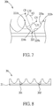
- FIG. 7 is a schematic side view illustrating portions of still another type of heat dissipation device 20b according to a preferred embodiment of the present invention.
- a first circle (not shown) may be defined based on a first center C5 and a first radius L31, and the first curved surface 224b may then be defined with its profile being a portion of the first circle.
- the first center C5 may be located within a first predefined region (not shown).
- the first predefined region is also a circular region, which centers at the second peak portion 222b and expands by a radius equaling half the first radius L31.
- a second circle (not shown) may be derived from a second center C6 and a second radius L32, and a portion of such second circle may be taken as the second curved surface 225b.
- a second predefined region R2 which is also circular, may be derived from the first peak portion 221b (as its center) and half the distance between the first peak portion 221b and the second peak portion 222b (as its radius).
- the second center C6 may be bounded by the circular second predefined region R2.
- the heat sink of the heat dissipation device 20b may further include a second plane surface 229a, which may be coupled between the second curved surface 225b and the second peak portion 222b.
- a second plane surface 229a which may be coupled between the second curved surface 225b and the second peak portion 222b.
- the largest surface area for the heat dissipation device would not be the best choice.
- best efficiency for heat dissipation can be achieved when the heat dissipation device has a sub-optimal surface area (which is slightly smaller than the largest surface area).
- arrangements for the first and second curved surfaces 224b and 225b as well as the additional second plane surface 229a may be adjusted or modified to reach the sub-optimal surface area.
- FIG. 8 is a schematic side view of the heat dissipation device 20 with openings, according to a preferred embodiment of the present invention.
- the heat dissipation device 20 may further include openings 201 and 202, which may be formed in the heat sink 22 and the heat conducting plate 21, and may penetrate the heat conducting plate 21. With the aids of the openings 201 and 202, the heat dissipation device 20 may be connected with or coupled to a heat emitting surface of a concerned object.
- the openings 201 and 202 may be screw holes, so as to secure or fix the heat dissipation device 20 to the heat emitting surface of the concerned object by screws.
- the heat dissipation device 20 may be attached to the heat emitting surface of the concerned object by heat conducting glue or heat dissipating grease.
- the heat dissipation device of the present invention features that, curved surfaces are provided for the heat sink, being disposed between corresponding peak portions and valley portions. Furthermore, each of the curved surfaces may have a curved profile, being a portion of a circle centering between the first peak portion and the second peak portion. Moreover, for each point along the curved profile, a corresponding extension line (i.e., a normal line, which is perpendicular to a tangent line at that point) may pass through the center of the above-identified circle. In other words, for each point along the curved profile, the corresponding extension line may pass between the first and second peak potions without contacting any portion of the heat sink.
- a corresponding extension line i.e., a normal line, which is perpendicular to a tangent line at that point
- heat radiated from the curved surfaces of the heat sink which is in the form of radiated electromagnetic waves (such as infrared-ray or far-infrared-ray), may travel along the extension lines between the first peak potion and the second peak portion.
- radiated electromagnetic waves such as infrared-ray or far-infrared-ray
- the heat dissipation device of the present invention may be also applied or utilized for waste heat recycling, thermal energy conduction or heaters.
Landscapes
- Engineering & Computer Science (AREA)
- Physics & Mathematics (AREA)
- Thermal Sciences (AREA)
- Mechanical Engineering (AREA)
- General Engineering & Computer Science (AREA)
- Microelectronics & Electronic Packaging (AREA)
- Cooling Or The Like Of Semiconductors Or Solid State Devices (AREA)
- Cooling Or The Like Of Electrical Apparatus (AREA)
Applications Claiming Priority (1)
| Application Number | Priority Date | Filing Date | Title |
|---|---|---|---|
| TW107147347A TW202024553A (zh) | 2018-12-27 | 2018-12-27 | 散熱裝置 |
Publications (1)
| Publication Number | Publication Date |
|---|---|
| EP3675152A1 true EP3675152A1 (de) | 2020-07-01 |
Family
ID=68965665
Family Applications (1)
| Application Number | Title | Priority Date | Filing Date |
|---|---|---|---|
| EP19217626.1A Withdrawn EP3675152A1 (de) | 2018-12-27 | 2019-12-18 | Wärmeableitungsvorrichtung |
Country Status (5)
| Country | Link |
|---|---|
| US (1) | US11215408B2 (de) |
| EP (1) | EP3675152A1 (de) |
| JP (1) | JP2020107886A (de) |
| CN (1) | CN111386007A (de) |
| TW (1) | TW202024553A (de) |
Families Citing this family (1)
| Publication number | Priority date | Publication date | Assignee | Title |
|---|---|---|---|---|
| US11774183B2 (en) * | 2020-09-01 | 2023-10-03 | City University Of Hong Kong | Heat transferring device and method for making thereof |
Citations (7)
| Publication number | Priority date | Publication date | Assignee | Title |
|---|---|---|---|---|
| DE4217289A1 (de) * | 1992-05-25 | 1993-12-16 | Mannesmann Ag | Fluidkühlung von Halbleiterelementen |
| DE10031465A1 (de) * | 2000-06-28 | 2002-01-17 | Eupec Gmbh & Co Kg | Kühleinrichtung für eine Schaltungsanordnung |
| EP1280202A2 (de) * | 2001-07-27 | 2003-01-29 | Hewlett-Packard Company | Hochleitungskühler |
| EP1398833A2 (de) * | 2002-09-10 | 2004-03-17 | Hewlett-Packard Development Company, L.P. | Passiver Hochleistungskühler mit Leitungskanälen |
| EP1473982A2 (de) * | 2003-04-30 | 2004-11-03 | Hewlett-Packard Development Company, L.P. | Kühlvorrichtung |
| US20080093730A1 (en) * | 2005-01-24 | 2008-04-24 | Toyota Jidosha Kabushiki Kaisha | Semiconductor Module And Semiconductor Device |
| US20100012294A1 (en) * | 2008-07-21 | 2010-01-21 | Raschid Jose Bezama | Structure and Apparatus for Cooling Integrated Circuits Using Cooper Microchannels |
Family Cites Families (27)
| Publication number | Priority date | Publication date | Assignee | Title |
|---|---|---|---|---|
| US3285333A (en) * | 1962-10-17 | 1966-11-15 | Garrett Corp | Geometrically-spectrally selective radiator |
| US3982527A (en) * | 1974-01-02 | 1976-09-28 | Cheng Chen Yen | Method and apparatus for concentrating, harvesting and storing of solar energy |
| US4313426A (en) * | 1978-03-13 | 1982-02-02 | Niedermeyer William P | Solar energy collector |
| US5368094A (en) * | 1993-11-02 | 1994-11-29 | Hung; Chin-Ping | Bipartite heat sink positioning device for computer chips |
| US7003970B2 (en) * | 2001-07-09 | 2006-02-28 | Daikin Industries, Ltd. | Power module and air conditioner |
| JP3707688B2 (ja) * | 2002-05-31 | 2005-10-19 | スタンレー電気株式会社 | 発光装置およびその製造方法 |
| JP4289027B2 (ja) * | 2002-07-25 | 2009-07-01 | 豊田合成株式会社 | 発光装置 |
| US20050152115A1 (en) * | 2004-01-09 | 2005-07-14 | Chui-Kai Peng | Thermal module |
| US7290598B2 (en) * | 2004-02-26 | 2007-11-06 | University Of Rochester | Heat exchange device |
| CN100411207C (zh) * | 2004-06-28 | 2008-08-13 | 京瓷株式会社 | 发光装置及照明装置 |
| US7204299B2 (en) * | 2004-11-09 | 2007-04-17 | Delphi Technologies, Inc. | Cooling assembly with sucessively contracting and expanding coolant flow |
| US8939683B1 (en) * | 2004-12-21 | 2015-01-27 | Robert Alvin White | Inverse square tool form |
| US7588074B1 (en) * | 2004-12-21 | 2009-09-15 | Robert Alvin White | In the rate of energy transfer across boundaries |
| US7433191B2 (en) * | 2005-09-30 | 2008-10-07 | Apple Inc. | Thermal contact arrangement |
| KR100827378B1 (ko) * | 2006-02-08 | 2008-05-07 | 엘지전자 주식회사 | 열확산 시트 |
| US7889421B2 (en) * | 2006-11-17 | 2011-02-15 | Rensselaer Polytechnic Institute | High-power white LEDs and manufacturing method thereof |
| DE102007019885B4 (de) * | 2007-04-27 | 2010-11-25 | Wieland-Werke Ag | Kühlkörper mit matrixförmig strukturierter Oberfläche |
| EP2417843A2 (de) * | 2009-04-08 | 2012-02-15 | NS Acquisition LLC | Kühlkörper mit niedriger spannungsinduktion |
| CN102080771A (zh) * | 2009-11-27 | 2011-06-01 | 富准精密工业(深圳)有限公司 | 发光二极管灯具 |
| WO2012079042A1 (en) * | 2010-12-09 | 2012-06-14 | Panasonic Avionics Corporation | Heatsink device and method |
| JP5234138B2 (ja) * | 2011-05-06 | 2013-07-10 | 船井電機株式会社 | 放熱板 |
| US20130168042A1 (en) * | 2012-01-04 | 2013-07-04 | General Electric Company | Heat exchanger having corrugated sheets |
| US20130250522A1 (en) * | 2012-03-22 | 2013-09-26 | Varian Medical Systems, Inc. | Heat sink profile for interface to thermally conductive material |
| US9743555B2 (en) * | 2013-04-02 | 2017-08-22 | Gerald Ho Kim | Silicon-based heat dissipation device for heat-generating devices |
| CN104582234A (zh) * | 2013-10-12 | 2015-04-29 | 富葵精密组件(深圳)有限公司 | 散热装置、其制作方法及具有散热装置的柔性电路板 |
| US10163754B2 (en) * | 2013-12-26 | 2018-12-25 | Taiwan Semiconductor Manufacturing Company, Ltd. | Lid design for heat dissipation enhancement of die package |
| US10448538B1 (en) * | 2017-12-10 | 2019-10-15 | Symantec Corporation | Apparatuses, systems, and methods for cooling wireless routers |
-
2018
- 2018-12-27 TW TW107147347A patent/TW202024553A/zh unknown
-
2019
- 2019-12-11 CN CN201911265525.7A patent/CN111386007A/zh active Pending
- 2019-12-12 US US16/711,589 patent/US11215408B2/en not_active Expired - Fee Related
- 2019-12-13 JP JP2019224985A patent/JP2020107886A/ja active Pending
- 2019-12-18 EP EP19217626.1A patent/EP3675152A1/de not_active Withdrawn
Patent Citations (7)
| Publication number | Priority date | Publication date | Assignee | Title |
|---|---|---|---|---|
| DE4217289A1 (de) * | 1992-05-25 | 1993-12-16 | Mannesmann Ag | Fluidkühlung von Halbleiterelementen |
| DE10031465A1 (de) * | 2000-06-28 | 2002-01-17 | Eupec Gmbh & Co Kg | Kühleinrichtung für eine Schaltungsanordnung |
| EP1280202A2 (de) * | 2001-07-27 | 2003-01-29 | Hewlett-Packard Company | Hochleitungskühler |
| EP1398833A2 (de) * | 2002-09-10 | 2004-03-17 | Hewlett-Packard Development Company, L.P. | Passiver Hochleistungskühler mit Leitungskanälen |
| EP1473982A2 (de) * | 2003-04-30 | 2004-11-03 | Hewlett-Packard Development Company, L.P. | Kühlvorrichtung |
| US20080093730A1 (en) * | 2005-01-24 | 2008-04-24 | Toyota Jidosha Kabushiki Kaisha | Semiconductor Module And Semiconductor Device |
| US20100012294A1 (en) * | 2008-07-21 | 2010-01-21 | Raschid Jose Bezama | Structure and Apparatus for Cooling Integrated Circuits Using Cooper Microchannels |
Also Published As
| Publication number | Publication date |
|---|---|
| US20200208926A1 (en) | 2020-07-02 |
| TW202024553A (zh) | 2020-07-01 |
| CN111386007A (zh) | 2020-07-07 |
| JP2020107886A (ja) | 2020-07-09 |
| US11215408B2 (en) | 2022-01-04 |
Similar Documents
| Publication | Publication Date | Title |
|---|---|---|
| CN101685330A (zh) | 散热装置及具有该散热装置的笔记本电脑 | |
| TWI603441B (zh) | 功率模組及其製造方法 | |
| CN209057439U (zh) | 一种多鳍片接触式散热片 | |
| TWM584591U (zh) | 散熱裝置 | |
| EP3675152A1 (de) | Wärmeableitungsvorrichtung | |
| JP2001085877A (ja) | 突起部を有する受熱面を備えたヒートシンク | |
| US20130233520A1 (en) | Flat heat pipe | |
| CN210607227U (zh) | 芯片散热结构和硬盘 | |
| CN210247322U (zh) | 散热器及具有该散热器的散热系统与医疗设备 | |
| CN209749023U (zh) | 一种石墨烯散热器 | |
| CN209435686U (zh) | 遥控器整体散热结构 | |
| CN209544581U (zh) | 一种室内定向天线结构 | |
| CN212588569U (zh) | 一种带有散热装置的柔性线路板 | |
| CN207395549U (zh) | 一种高效散热冷锻散热器 | |
| CN104754915A (zh) | 应用于移动装置的散热结构 | |
| CN220171501U (zh) | 工控机及计算机 | |
| CN208589434U (zh) | 一种柔性膜片散热器 | |
| CN209358905U (zh) | 散热器、散热系统及电子设备 | |
| TWI912091B (zh) | 散熱裝置與包含其的顯示卡模組 | |
| CN105899043A (zh) | 一种具有电磁屏蔽功能的散热装置 | |
| CN223065717U (zh) | 散热结构和电子设备 | |
| CN223872643U (zh) | 散热鳍片组件及包括该散热鳍片组件的散热器 | |
| CN107396613B (zh) | 一种翅片距离规律变化的圆弧形截面的电子元件散热器 | |
| CN221553770U (zh) | 雷达及其金属散热扼流槽 | |
| CN222017098U (zh) | 一种散热器 |
Legal Events
| Date | Code | Title | Description |
|---|---|---|---|
| PUAI | Public reference made under article 153(3) epc to a published international application that has entered the european phase |
Free format text: ORIGINAL CODE: 0009012 |
|
| STAA | Information on the status of an ep patent application or granted ep patent |
Free format text: STATUS: THE APPLICATION HAS BEEN PUBLISHED |
|
| AK | Designated contracting states |
Kind code of ref document: A1 Designated state(s): AL AT BE BG CH CY CZ DE DK EE ES FI FR GB GR HR HU IE IS IT LI LT LU LV MC MK MT NL NO PL PT RO RS SE SI SK SM TR |
|
| AX | Request for extension of the european patent |
Extension state: BA ME |
|
| STAA | Information on the status of an ep patent application or granted ep patent |
Free format text: STATUS: THE APPLICATION IS DEEMED TO BE WITHDRAWN |
|
| 18D | Application deemed to be withdrawn |
Effective date: 20210112 |