EP3675203B1 - Batterie secondaire et module de batterie - Google Patents
Batterie secondaire et module de batterie Download PDFInfo
- Publication number
- EP3675203B1 EP3675203B1 EP19180052.3A EP19180052A EP3675203B1 EP 3675203 B1 EP3675203 B1 EP 3675203B1 EP 19180052 A EP19180052 A EP 19180052A EP 3675203 B1 EP3675203 B1 EP 3675203B1
- Authority
- EP
- European Patent Office
- Prior art keywords
- current collecting
- sheet
- axial direction
- collecting sheet
- electrode
- Prior art date
- Legal status (The legal status is an assumption and is not a legal conclusion. Google has not performed a legal analysis and makes no representation as to the accuracy of the status listed.)
- Active
Links
Images


Classifications
-
- H—ELECTRICITY
- H01—ELECTRIC ELEMENTS
- H01M—PROCESSES OR MEANS, e.g. BATTERIES, FOR THE DIRECT CONVERSION OF CHEMICAL ENERGY INTO ELECTRICAL ENERGY
- H01M50/00—Constructional details or processes of manufacture of the non-active parts of electrochemical cells other than fuel cells, e.g. hybrid cells
- H01M50/10—Primary casings; Jackets or wrappings
- H01M50/102—Primary casings; Jackets or wrappings characterised by their shape or physical structure
- H01M50/103—Primary casings; Jackets or wrappings characterised by their shape or physical structure prismatic or rectangular
-
- H—ELECTRICITY
- H01—ELECTRIC ELEMENTS
- H01M—PROCESSES OR MEANS, e.g. BATTERIES, FOR THE DIRECT CONVERSION OF CHEMICAL ENERGY INTO ELECTRICAL ENERGY
- H01M10/00—Secondary cells; Manufacture thereof
- H01M10/04—Construction or manufacture in general
- H01M10/0431—Cells with wound or folded electrodes
-
- H—ELECTRICITY
- H01—ELECTRIC ELEMENTS
- H01M—PROCESSES OR MEANS, e.g. BATTERIES, FOR THE DIRECT CONVERSION OF CHEMICAL ENERGY INTO ELECTRICAL ENERGY
- H01M50/00—Constructional details or processes of manufacture of the non-active parts of electrochemical cells other than fuel cells, e.g. hybrid cells
- H01M50/20—Mountings; Secondary casings or frames; Racks, modules or packs; Suspension devices; Shock absorbers; Transport or carrying devices; Holders
- H01M50/204—Racks, modules or packs for multiple batteries or multiple cells
- H01M50/207—Racks, modules or packs for multiple batteries or multiple cells characterised by their shape
- H01M50/209—Racks, modules or packs for multiple batteries or multiple cells characterised by their shape adapted for prismatic or rectangular cells
-
- H—ELECTRICITY
- H01—ELECTRIC ELEMENTS
- H01M—PROCESSES OR MEANS, e.g. BATTERIES, FOR THE DIRECT CONVERSION OF CHEMICAL ENERGY INTO ELECTRICAL ENERGY
- H01M50/00—Constructional details or processes of manufacture of the non-active parts of electrochemical cells other than fuel cells, e.g. hybrid cells
- H01M50/50—Current conducting connections for cells or batteries
- H01M50/531—Electrode connections inside a battery casing
- H01M50/533—Electrode connections inside a battery casing characterised by the shape of the leads or tabs
-
- H—ELECTRICITY
- H01—ELECTRIC ELEMENTS
- H01M—PROCESSES OR MEANS, e.g. BATTERIES, FOR THE DIRECT CONVERSION OF CHEMICAL ENERGY INTO ELECTRICAL ENERGY
- H01M50/00—Constructional details or processes of manufacture of the non-active parts of electrochemical cells other than fuel cells, e.g. hybrid cells
- H01M50/50—Current conducting connections for cells or batteries
- H01M50/531—Electrode connections inside a battery casing
- H01M50/536—Electrode connections inside a battery casing characterised by the method of fixing the leads to the electrodes, e.g. by welding
-
- H—ELECTRICITY
- H01—ELECTRIC ELEMENTS
- H01M—PROCESSES OR MEANS, e.g. BATTERIES, FOR THE DIRECT CONVERSION OF CHEMICAL ENERGY INTO ELECTRICAL ENERGY
- H01M50/00—Constructional details or processes of manufacture of the non-active parts of electrochemical cells other than fuel cells, e.g. hybrid cells
- H01M50/50—Current conducting connections for cells or batteries
- H01M50/531—Electrode connections inside a battery casing
- H01M50/538—Connection of several leads or tabs of wound or folded electrode stacks
-
- H—ELECTRICITY
- H01—ELECTRIC ELEMENTS
- H01M—PROCESSES OR MEANS, e.g. BATTERIES, FOR THE DIRECT CONVERSION OF CHEMICAL ENERGY INTO ELECTRICAL ENERGY
- H01M10/00—Secondary cells; Manufacture thereof
- H01M10/05—Accumulators with non-aqueous electrolyte
- H01M10/052—Li-accumulators
- H01M10/0525—Rocking-chair batteries, i.e. batteries with lithium insertion or intercalation in both electrodes; Lithium-ion batteries
-
- H—ELECTRICITY
- H01—ELECTRIC ELEMENTS
- H01M—PROCESSES OR MEANS, e.g. BATTERIES, FOR THE DIRECT CONVERSION OF CHEMICAL ENERGY INTO ELECTRICAL ENERGY
- H01M50/00—Constructional details or processes of manufacture of the non-active parts of electrochemical cells other than fuel cells, e.g. hybrid cells
- H01M50/50—Current conducting connections for cells or batteries
- H01M50/502—Interconnectors for connecting terminals of adjacent batteries; Interconnectors for connecting cells outside a battery casing
- H01M50/505—Interconnectors for connecting terminals of adjacent batteries; Interconnectors for connecting cells outside a battery casing comprising a single busbar
-
- Y—GENERAL TAGGING OF NEW TECHNOLOGICAL DEVELOPMENTS; GENERAL TAGGING OF CROSS-SECTIONAL TECHNOLOGIES SPANNING OVER SEVERAL SECTIONS OF THE IPC; TECHNICAL SUBJECTS COVERED BY FORMER USPC CROSS-REFERENCE ART COLLECTIONS [XRACs] AND DIGESTS
- Y02—TECHNOLOGIES OR APPLICATIONS FOR MITIGATION OR ADAPTATION AGAINST CLIMATE CHANGE
- Y02E—REDUCTION OF GREENHOUSE GAS [GHG] EMISSIONS, RELATED TO ENERGY GENERATION, TRANSMISSION OR DISTRIBUTION
- Y02E60/00—Enabling technologies; Technologies with a potential or indirect contribution to GHG emissions mitigation
- Y02E60/10—Energy storage using batteries
-
- Y—GENERAL TAGGING OF NEW TECHNOLOGICAL DEVELOPMENTS; GENERAL TAGGING OF CROSS-SECTIONAL TECHNOLOGIES SPANNING OVER SEVERAL SECTIONS OF THE IPC; TECHNICAL SUBJECTS COVERED BY FORMER USPC CROSS-REFERENCE ART COLLECTIONS [XRACs] AND DIGESTS
- Y02—TECHNOLOGIES OR APPLICATIONS FOR MITIGATION OR ADAPTATION AGAINST CLIMATE CHANGE
- Y02P—CLIMATE CHANGE MITIGATION TECHNOLOGIES IN THE PRODUCTION OR PROCESSING OF GOODS
- Y02P70/00—Climate change mitigation technologies in the production process for final industrial or consumer products
- Y02P70/50—Manufacturing or production processes characterised by the final manufactured product
Definitions
- the disclosure relates to the technical field of battery, and in particular to a secondary battery and a battery module.
- a secondary battery includes an electrode assembly and a current collecting unit connected to the electrode assembly.
- the electrode assembly comprises an end surface and a tab extending from the end surface. Since the preformed gap between the current collecting unit and the end surface is small, it is difficult to use a welding device to weld the current collecting unit and the tab, and thereby welding defect may occur at the current collecting unit and the tab.
- EP2557609A discloses a rechargeable battery including a plurality of electrode assemblies including pair of electrode tabs protruding to both sides; a case receives the plurality of electrode assemblies; and first and second current collecting plates cover openings formed on both sides of the case.
- CN108198989A discloses a connection member for a rechargeable battery, including a guide plate, two first connection plates and a second connection plate.
- Document US2014/349149 discloses a secondary batteries having a current collecting unit attached to tab portions of the electrode assemblies.
- US2017279157A1 discloses a rechargeable battery including: a first electrode assembly and a second electrode assembly, each including a first electrode and a second electrode configured with an electrode plate and an electrode uncoated region; a case for receiving the first electrode assembly and the second electrode assembly and including an opening; a cap assembly combined with the case to seal the opening; and a current collecting member electrically connected between the electrode uncoated region of the first electrode assembly and the electrode uncoated region of the second electrode assembly.
- JP2007073317A discloses a wound pole group 100 including a plurality of wound power generation elements 101 and L-shaped current collector plates 102 and 102 that hold a stack of the plurality of wound power generation elements 101 from both sides.
- a secondary battery and a battery module there is provided a secondary battery and a battery module.
- the tab of the secondary battery can be connected to the cap assembly through the current cohering unit.
- the current collecting unit according to embodiments has a simple and compact structure, and it is advantageous to increase the energy density of the secondary battery.
- embodiments of the disclosure provide a case comprising a receiving hole having an opening; a cap assembly sealingly connected with the case to close the opening; an electrode assembly disposed in the receiving hole, wherein the electrode assembly comprises two end surfaces opposite to each other in a first direction perpendicular to an axial direction of the receiving hole and tabs extending from respective end surfaces, and the electrode assembly comprises two or more electrode units which are stacked in the axial direction; and a current collecting unit comprising a first sheet and a first current collecting sheet connected to the first sheet, wherein both the first sheet and the first current collecting sheet extend in the axial direction, and the tab is bent with respect to the first direction and is electrically connected to the first current collecting sheet.
- the first current collecting sheet comprises a first connecting end connected to the first sheet, and the first connecting end extends in a second direction perpendicular to both the axial direction and the first direction.
- the first current collecting sheet is disposed at a side of the first sheet close to the case, and the tab is fixedly connected to a surface of the first current collecting sheet away from the first sheet.
- the current collecting unit further comprises a second current collecting sheet connected to the first sheet, wherein both the first current collecting sheet and the second current collecting sheet extend in the axial direction, the first current collecting sheet and the second current collecting sheet are disposed to at least partly overlap with each other in the axial direction, and there are two electrode assemblies stacked in the axial direction, wherein the tab of one of the two electrode assemblies is electrically connected to the first current collecting sheet, and the tab of the other of the two electrode assemblies is electrically connected to the second current collecting sheet.
- both the first current collecting sheet and the second current collecting sheet are disposed at a side of the first sheet close to the case, and the first current collecting sheet and the second current collecting sheet extend toward each other.
- the first sheet comprises a body portion extending in the axial direction and a first extending portion connected to the body portion, wherein the first extending portion extends outside of the body portion in the second direction perpendicular to both the axial direction and the first direction, and the first current collecting sheet and the second current collecting sheet are connected to two ends of the first extending portion in the axial direction, respectively.
- the first sheet further comprises a second extending portion connected to the body portion, wherein the first extending portion and the second extending portion are spaced apart in the axial direction to form a clearance notch, and in the axial direction, the clearance notch is disposed at a side of the first current collecting sheet close to the cap assembly, and the tab is able to pass through the clearance notch to connect with the first current collecting sheet.
- the clearance notch extends in the second direction beyond the first current collecting sheet.
- the first extending portion overlaps with the second extending portion.
- the current collecting unit further comprises a second sheet connected to the cap assembly, wherein the body portion and the second sheet are disposed to intersect with each other, and the first sheet, the second sheet, the first current collecting sheet and the second current collecting sheet are integrally formed.
- the electrode assembly is disposed between the two current collecting units, and the two current collecting units are connected to respective tabs through the first current collecting sheets.
- each electrode assembly comprises two electrode units
- the electrode unit comprises a sub-end-surface and a sub-tab extending from the sub-end-surface, two sub-end-surfaces at a same side form the end surface, two sub-tabs at a same side connect together and form the tab, and the sub-tab of one electrode unit extends in the axial direction from a side of the sub-end-surface close to the other electrode unit.
- the electrode unit comprises two wide surfaces and two narrow surfaces for connecting the two wide surfaces, wherein the two wide surfaces are disposed opposite to each other in the axial direction, the wide surfaces and the narrow surfaces are alternatively disposed, and the tab extends from a region of the end surface close to the two adjacent wide surfaces of the two electrode units.
- the secondary battery comprises a case having a receiving hole, an electrode assembly disposed within the case, and a current collecting unit for inputting electric energy to the electrode assembly or outputting electric energy from the electrode assembly.
- the current collecting unit comprises a first sheet and a first current collecting sheet connected to the first sheet. Both the first sheet and the first current collecting sheet extend in the axial direction. Since the first sheet is close to the electrode assembly while the first current collecting sheet is away from the electrode assembly, a clearance space can be formed, which facilitates the welding of the first current collecting sheet and the tab through a welding device. Thereby, the welding difficulty can be effectively reduced and welding quality can be improved. On the other hand, since the first current collecting sheet extends in the axial direction, the occupied space in the first direction can be reduced, and it is also advantageous to increase the energy density of the secondary battery.
- embodiments of the disclosure provide a battery module comprising two or more secondary batteries according to the above embodiments which are arranged side by side.
- the present invention is defined by the features of claim 1 and relates to a secondary battery.
- a battery module 20 and a secondary battery 10 according to embodiments of the disclosure will be described below in detail with reference to Figs. 1 to 8 .
- the embodiments of the disclosure further provide a battery module 20, comprising two or more secondary batteries 10 according to the embodiment and a busbar for connecting two of the secondary batteries 10.
- the two or more secondary batteries 10 are arranged side by side in one direction.
- One end of the busbar is fixedly connected to one of two secondary batteries 10, and the other end of the busbar is fixedly connected to the other one of the two secondary batteries 10.
- the two or more secondary batteries 10 according to the embodiment are arranged side by side in their thickness direction to form the battery module 20.
- the secondary battery 10 comprises a case 11, an electrode assembly 13 disposed in the case 11, and a cap assembly 12 that is sealingly connected with the case 11.
- the case 11 may be formed in a shape of quadrangular prism or in other shapes.
- the case 11 comprises a receiving hole 11a having an opening.
- the receiving hole 11a can accommodate the electrode assembly 13 and electrolyte.
- the case 11 can be made of a material such as aluminum, aluminum alloy and plastic.
- the electrode assembly 13 comprises two end surfaces 13a opposite to each other in a first direction Y perpendicular to an axial direction X of the receiving hole 11a and tabs 13b extending from each end surface 13a.
- each tab 13b extends from an end surface 13a of the electrode assembly 13.
- Each electrode assembly 13 comprises two tabs 13b opposite to each other in the first direction Y, wherein a tab 13b is a positive tab, and the other is a negative tab.
- the electrode assembly 13 comprises two or more electrode units 131 stacked in the axial direction X of the receiving hole 11a.
- a body of the electrode unit 131 and a sub-tab connected to the body can be formed by stacking or winding a first electrode plate, a second electrode plate, and a separator together.
- the separator is an insulator between the first electrode plate and the second electrode plate.
- the electrode unit 131 according to the embodiment comprises a layer of separator, a layer of first electrode plate, another layer of separator and a layer of second electrode plate.
- the description is made by exemplarily taking the first electrode plate as a positive electrode plate and the second electrode plate as a negative electrode plate.
- the first electrode plate may be a negative electrode plate
- the second electrode plate may be a positive electrode plate
- a positive active material is coated on a coating region of the positive electrode plate
- a negative active material is coated on a coating region of the negative electrode plate.
- An uncoated region extending from the body serves as the sub-tab.
- An electrode unit 131 comprises two sub-tabs opposite to each other in the first direction Y, i.e., a positive tab and a negative tab.
- the positive tab extends from the coating region of the positive electrode plate while the negative tab extends from the coating region of the negative electrode plate.
- the first direction Y is perpendicular to the axial direction X.
- each electrode assembly 13 comprises sub-end-surfaces 131c of the respective electrode units 131, while tabs 13b of an electrode assembly 13 comprise sub-tabs 131d of respective electrode units 131.
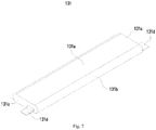
- the electrode unit 131 has a flat shape comprising two wide surfaces and two narrow surfaces 131b connecting the two wide surfaces 131a.
- the two wide surfaces 131a are disposed opposite to each other in the axial direction X.
- the wide surfaces 131a and the narrow surfaces 131b are alternately arranged.
- the cap assembly 12 is sealingly connected with the case 11 to close the opening.
- the cap assembly 12 comprises a cap plate 121 and electrode terminals 122.
- the cap assembly 12 is sealingly connected with the case 11 through the cap plate 121.
- the electrode terminal 122 is disposed on the cap plate 121 and is electrically connected to the electrode assembly 13 through a current collecting unit.
- the secondary battery 10 comprises a current collecting unit 14 for connecting the electrode assembly 13 and the cap assembly 12.
- the tab 13b is connected to the electrode terminal 122 through the current collecting unit 14.
- the current collecting unit 14 according to the embodiment comprises a first sheet 141 and a first current collecting sheet 14a connected to the first sheet 141. Both the first sheet 141 and the first current collecting sheet 14a extend in the axial direction X. In an embodiment, in the X direction, both a thickness direction of the first current collecting sheet 14a and a thickness direction of the first sheet 141 are identical with the first direction Y. Furthermore, the first current collecting sheet 14a and the first sheet 141 are disposed to at least partly overlap with each other.
- the first sheet 141 is disposed between an end surface 13a of the electrode assembly 13 and the case 11, while the first current collecting sheet 14a is connected to a part of the first sheet 141 between the end surface 13a of the electrode assembly 13 and the case 11.
- the tab 13b is bent with respect to the first direction Y and electrically connected to the first current collecting sheet 14a.
- the bent portion of the tab 13b extends in the axial direction X.
- the first current collecting sheet 14a, the first sheet 141 and a portion of the tab 13b connected to the first current collecting sheet 14a at least partly overlap with each other.
- the secondary battery 10 comprises a case 11 having a receiving hole 11a, an electrode assembly 13 disposed in the case 11 and a current collecting unit 14 for inputting electric energy to the electrode assembly 13 or outputting electric energy from the electrode assembly 13.
- the current collecting unit 14 comprises a first sheet 141 and a first current collecting sheet 14a connected to the first sheet 141. Both the first current collecting sheet 14a and the first sheet 141 extend in the axial direction X of the receiving hole 11a. Since the current collecting unit 14 according to embodiments of the disclosure comprises the first sheet 141 and the first current collecting sheet 14a, the first sheet 141 and the first current collecting sheet 14a are small in size and occupy small space in the case 11.
- the current collecting unit 14 can electrically connect the tab 13b of the electrode assembly 13 to the electrode terminal 122 of the cap assembly 12.
- the first current collecting sheet 14a comprises the first current collecting sheet 14a for electrically connecting the tab 13b.
- the first current collecting sheet 14a can be fixedly connected to the corresponding tab 13b.
- the current collecting unit 14 according to the embodiment is fixedly connected to the tab 13b through the first current collecting sheet 14a disposed on the first sheet 141.
- the first current collecting sheet 14a is far from the electrode assembly 13. Therefore, there will be a clearance space such that the first current collecting sheet 14a and the tab 13b can be welded through a welding device. Accordingly, welding difficulty can be effectively reduced and welding quality can be improved. Furthermore, it is advantageous to improve stability of the connection between the first current collecting sheet 14a and the tab 13b such that they cannot be easily separated from each other, and the stability and safety of the battery module 20 in use can be ensured.
- the first current collecting sheet 14a comprises a first connecting end 14c connected to the first sheet 141.
- the first connecting end 14c extends in a second direction Z perpendicular to both the axial direction X and the first direction Y.
- the second direction Z is parallel to a thickness direction of the secondary battery 10.
- the first current collecting sheet 14a is connected to the first sheet 141 through the first connecting end 14c. Since the first connecting end 14c extends in the second direction Z, it is ensured that the first current collecting sheet 14a has a large surface area away from the electrode assembly 13, and thus the connection of the tab 13b and the first current collecting sheet 14a is more reliable.
- the length of the tab 13b in the second direction Z is greater than its thickness in the axial direction X, and the length of the first current collecting sheet 14a in the second direction Z is greater than its thickness in the first direction Y.
- the first current collecting sheet 14a has a rectangular shape.
- the first current collecting sheet 14a and the tab 13b according to the embodiment may be connected by ultrasonic welding.
- the first current collecting sheet 14a is located on a side of the first sheet 141 close to the case 11.
- the tab 13b is fixedly connected to a surface of the first current collecting sheet 14a away from the first sheet 141.
- the first sheet 141 is disposed between the first current collecting sheet 14a and the end surface 13a of the electrode assembly 13.
- the first current collecting sheet 14a does not contact with the end surface 13a of the electrode assembly 13, thus it is prevented that the first current collecting sheet 14a scratches or damages the electrode unit 131 in the electrode assembly 13 during the mounting or operation process.
- the tab 13b Since the tab 13b is fixedly connected to a surface of the first current collecting sheet 14a away from the first sheet 141, a free end of the tab 13b will not be folded during the mounting or operation process to contact with the end surface 13a of the electrode assembly 13. Thereby, it is advantageous to reduce the possibility that the tab 13b is folded to insert into the end surface 13a and thus cause structural damage or breakage of the electrode unit 131. Furthermore, the tab 13b, the first current collecting sheet 14a and the first sheet 141 in the first direction Y have a small total thickness, thus the occupied space between the end surface 13a and the case 11 can be effectively reduced, and the energy density of the secondary battery 10 can be effectively improved.
- the current collecting unit 14 further comprises a second current collecting sheet 14b connected to the first sheet 141.
- Both the first current collecting sheet 14a and the second current collecting sheet 14b extend in the axial direction X, and they at least partially overlap with each other in the axial direction X. Thereby, the dimension of the first current collecting sheet 14a and the second current collecting sheet 14b in the second direction Z can be reduced.
- the second current collecting sheet 14b comprises a second connecting end extending in the second direction Z.
- the second current collecting sheet 14b is connected to the first sheet 141 through the second connecting end.
- the two electrode assemblies 13 are stacked in the axial direction X.
- the tab 13b of one of the electrode assemblies 13 is electrically connected to the first current collecting sheet 14a, and the tab 13b of the other of the electrode assemblies 13 is electrically connected to the second current collecting sheet 14b.
- the tabs 13b of the two electrode assemblies 13 at a same side are connected through the first current collecting sheet 14a and the second current collecting sheet 14b such that current collection can be achieved. In this way, on the one hand, it can be avoided that when a plurality of electrode units 131 are connected to the first current collecting sheet 14a through one tab 13b, the temperature at the connection between the tab 13b and the first current collecting sheet 14a will be excessively high.
- the tab 13b extends a short distance to fixedly connect with the corresponding first current collecting sheet 14a or the corresponding second current collecting sheet 14b, such that the tab 13b does not need to extend a long distance from the end surface 13a for being connected to the first current collecting sheet 14a. Therefore, the electrode unit 131 can have uniform size and uniform manufacturing process, and it is possible to reduce the manufacturing difficulty and cost.
- each electrode assembly 13 comprises two electrode units 131.
- the electrode unit 131 comprises a sub-end-surface 131c and a sub-tab 131d extending from the sub-end-surface 131c.
- the two sub-end-surfaces 131c at a same side form the end surface 13a, while the two sub-tabs 131d at a same side connect together and form the tab 13b.
- the sub-tab 131d of one electrode unit 131 extends in the axial direction from a region of the sub-end-surface 131c close to another electrode unit 131.
- the respective sub-tabs 131d of the two electrode units 131 are close to each other and extend short distances to connect together and form the tab 13b that will be fixedly connected to the first current collecting sheet 14a and the second current collecting sheet 14b.
- the sub-tab 131d do not extend an excess distance to have a redundant length.
- the sub-tab 131d is likely to be broken and fractured at the stress concentration region.
- the extending dimension of the sub-tab 131d is controlled within a small range. The occupied space of the tab 13b formed by the sub-tabs 131d is reduced, and the energy density of the secondary battery 10 is increased.
- both the first current collecting sheet 14a and the second current collecting sheet 14b are located on a same side of the first sheet 141 close to the case 11. Both the first current collecting sheet 14a and the second current collecting sheet 14b extend in the axial direction X. The first current collecting sheet 14a and the second current collecting sheet 14b extend toward each other such that the first current collecting sheet 14a and the second current collecting sheet 14b are spaced apart from the end surface 13a by the first sheet 141. Thereby, neither the first current collecting sheet 14a nor the second current collecting sheet 14b will contact with the end surface 13a of the electrode assembly 13.
- the thickness direction of the second current collecting sheet 14b is identical with the thickness direction of the first sheet 141, and their thickness directions are identical with the first direction Y.
- the second current collecting sheet 14b and the first current collecting sheet 14a have the same structure.
- the second current collecting sheet 14b and the tab 13b according to the embodiment may be connected by ultrasonic welding.
- the first sheet 141 comprises a body portion 141a extending in the axial direction X and a first extending portion 141b connected to the body portion 141a.
- the first extending portion 141b extends outside of the body portion 141a in the second direction Z perpendicular to both the axial direction X and the first direction Y.
- the first current collecting sheet 14a and the second current collecting sheet 14b are connected to two respective ends of the first extending portion 141b in the axial direction X.
- the two electrode assemblies 13 are stacked in the axial direction X, and thus the respective tabs 13b are spaced apart in the axial direction X.
- the two tabs 13b on a same side of the electrode assembly 13 can pass over the two opposite ends of the first extending portion 141b in the axial direction X, and then be fixedly connected to the first current collecting sheet 14a and the second current collecting sheet 14b, respectively. Since the first current collecting sheet 14a and the second current collecting sheet 14b are respectively connected to the two opposite ends of the first extending portion 141b, an extended size of the tab 13b does not need to be too long to be fixedly connected with the first current collecting sheet 14a or the second current collecting sheet 14b. Therefore, the extended length of the tab 13b can be effectively shortened. It is advantageous to reduce the occupied space of the tab 13b, improve the energy density of the secondary battery 10, and effectively reduce the manufacturing cost.
- the first sheet 141 further comprises a second extending portion 141c connected to the body portion 141a.
- the first extending portion 141b and the second extending portion 141c are spaced apart in the axial direction X to form a clearance notch 141d.
- the clearance notch 141d is located on a side of the first current collecting sheet 14a close to the cap assembly 12.
- the tab 13b can pass through the clearance notch 141d to be connected to the first current collecting sheet 14a.
- the first sheet 141 may be electrically connected to the electrode terminal 122 through the body portion 141a and the second extending portion 141c.
- the second extension portion 141c can improve the strength and rigidity of the first sheet 141 and the current passing area of the first sheet 141.
- the clearance notch 141d extends in the second direction Z perpendicular to both the axial direction X and the first direction Y and passes beyond the first current collecting sheet 14a. Therefore, when the tab 13b passes through the clearance notch 141d, the tab 13b will not contact with the body portion 141a, and thus the tab 13b will not be pressed by the body portion 141a, which reduces the possibility that the tab 13b deforms or is damaged due to pressure from the body portion 141a. The possibility can be reduced that the displacement of the tab 13b leads to an inaccurate and unstable connection region between the tab 13b and the first current collecting sheet 14a.
- the clearance structure can be a slot extending in the second direction Z.
- the second extending portion 141c and at least a part of the first extending portion 141b are disposed to overlap with each other in the axial direction X.
- the clearance notch 141d is designed on the first sheet 141 while ensuring that a connection transition region between the body portion 141a and the second sheet have a large current passing area.
- the current collecting unit 14 further comprises a second sheet 142 connected to the cap assembly 12.
- the body portion 141a and the second sheet 142 are disposed to intersect with each other.
- the second sheet 142 extends in the first direction Y.
- the thickness direction of the second sheet 142 is identical with the axial direction X.
- the second sheet 142 comprises a protrusion 142a away from the electrode assembly 13.
- the second sheet 142 is electrically connected to the electrode terminal 122 in the cap assembly 12 through the protrusion 142a.
- the first sheet 141, the second sheet 142, the first current collecting sheet 14a and the second current collecting sheet 14b are integrally formed. Thereby, on one hand, the overall structural strength and impact resistance of the current collecting unit 14 can be ensured.
- the current collecting unit 14 can be manufactured with an integral molding process, which reduces the number of processing steps and reduces the manufacturing cost.
- two tabs 13b of an electrode assembly 13 comprise a positive tab and a negative tab.
- the first current collecting sheet 14a of the current collecting unit 14 may be electrically connected to the positive tab or negative tab.
- the two current collecting units 14 are spaced apart in the first direction Y. In the first direction Y, the electrode assembly 13 is disposed between the two current collecting units 14.
- the body of the electrode unit 131 of the electrode assembly 13 is disposed between the two current collecting units 14, and the two tabs 13b of the electrode assembly 13 correspond to the two current collecting units 14, respectively.
- One tab 13b is connected to one current collecting unit 14, and the other tab 13b is connected to the other current collecting unit 14.
- the two current collecting units 14 are electrically connected to the corresponding tabs 13b through the first current collecting sheets 14a.
- the electrode assembly 13 comprises two electrode units 131.
- the electrode unit 131 comprises two wide surfaces 131a and two narrow surfaces 131b connecting the two wide faces 131a.
- the two wide surfaces 131a are disposed opposite to each other in the axial direction X.
- the wide surfaces 131a and the narrow surfaces 131b are alternately disposed.
- the tab 13b extends from a region of the end surface 13a close to the two adjacent wide surfaces 131a of the two electrode units 131. Therefore, in the axial direction X, the tab 13b is substantially in a central region of the end surface 13a, it is ensured that the two sub-tabs 131d extending from the two electrode units 131 have substantially the same size.
- the electrode units 131 can be manufactured in identical process, and thus the manufacturing cost can be reduced.
- the battery module 20 comprises a plurality of secondary batteries 10 arranged side by side in a same direction.
- the electrode units 131 in the respective secondary batteries 10 according to the embodiment are stacked in the axial direction X of the receiving hole 11a of the case 11.
- the electrode unit 131 according to the embodiment expands, it mainly expands and deforms in the axial direction X of the receiving hole 11a, and it has a small expansion in a direction in which the secondary batteries 10 are arranged.
- a resultant expansion force accumulated in an arrangement direction of the respective secondary batteries 10 is small.
- the battery module 20 does not need to use a structural member having a higher strength to restrain and counteract the expansion force, and a structural member with a lower strength may be used to restrain and counteract the expansion force.
- the weight of the battery module 20 can be effectively reduced, the battery module 20 may have a more compact structure, and the energy density of the battery module 20 can be effectively increased.
- the battery module 20 has a small expansion or has no expansion in a thickness direction of the secondary battery 10, thus the safety in use can be effectively improved.
Landscapes
- Chemical & Material Sciences (AREA)
- Chemical Kinetics & Catalysis (AREA)
- Electrochemistry (AREA)
- General Chemical & Material Sciences (AREA)
- Engineering & Computer Science (AREA)
- Manufacturing & Machinery (AREA)
- Connection Of Batteries Or Terminals (AREA)
Claims (13)
- Batterie secondaire (10), comprenant :un boîtier (11) pourvu d'un trou de réception (11a) ayant une ouverture ;un ensemble de couvercle (12) connecté de manière étanche au boîtier (11) pour fermer l'ouverture ;un ensemble d'électrodes (13) disposé à l'intérieur du trou de réception (11a), dans laquelle l'ensemble d'électrodes (13) comprend deux faces d'extrémité (13a) en opposées l'une à l'autre dans une première direction (Y) perpendiculaire à une direction axiale (X) du trou de réception (11a) et deux languettes (13b) s'étendant à partir des faces d'extrémité (13a) respectives, l'ensemble d'électrodes (13) comprend deux ou plusieurs ensemble d'électrodes (131) superposées dans la direction axiale (X), et une unité d'électrode (131) présente une forme plate comprenant deux surfaces larges (131a) et deux surfaces étroites (131b) connectées aux deux surfaces larges (131a), les deux surfaces larges (131a) étant disposées en opposées l'une à l'autre dans la direction axial (X), et les surfaces larges (131a) et les surfaces étroites (131b) étant disposées en alternance ; etune unité collectrice de courant (14) comprenant une première feuille (141) et une première feuille collectrice de courant (14a) connectée à la première feuille (141), dans laquelle chacune de la première feuille (141) et de la première feuille collectrice de courant (14a) s'étendent dans la direction axiale (X), la première feuille collectrice de courant (14a) est disposée sur un côté de la première feuille (141) proche du boîtier (11), une languette correspondant (13b) aux deux languettes est courbée vers la première direction (Y) et est connectée de manière fixe à une surface de la première feuille collectrice de courant (14a) éloignée de la première feuille (141).
- Batterie secondaire (10) selon la revendication 1, caractérisée en ce que, la première feuille collectrice de courant (14a) comprend une première extrémité de connexion (14c) connectée à la première feuille (141), et la première extrémité de connexion (14c) s'étend dans une deuxième direction (Z) perpendiculaire à la fois à la direction axiale (X) et à la première direction (Y).
- Batterie secondaire (10) selon la revendication 1 ou 2, caractérisée en ce que l'unité collectrice de courant (14) comprend en outre une deuxième feuille collectrice de courant (14b) connectée à la première feuille (141), dans laquelle chacune de la première feuille collectrice de courant (14a) et de la deuxième feuille collectrice de courant (14b) s'étendent dans la direction axiale (X), la première feuille collectrice de courant (14a) et la deuxième feuille collectrice de courant (14b) sont disposées en se chevauchant au moins partiellement dans la direction axiale (X) et deux ensembles d'électrodes (13) sont superposées dans la direction axiale (X), une languette correspondant (13b) à l'un des deux ensembles d'électrodes (13) étant connectée électriquement à la première feuille collectrice de courant (14a), et une patte languette (13b) à l'autre des deux ensembles d'électrodes (13) étant connectée électriquement à la deuxième feuille collectrice de courant (14b).
- Batterie secondaire (10) selon la revendication 3, caractérisée en ce que, chacune de la première feuille collectrice de courant (14a) et de la deuxième feuille collectrice de courant (14b) est disposée sur un côté de la première feuille (141) proche du boîtier (11), et la première feuille collectrice de courant (14a) et la deuxième feuille collectrice de courant (14b) s'étendent l'une vers l'autre.
- Batterie secondaire (10) selon la revendication 3, caractérisée en ce que, la première feuille (141) comprend une part de corps (141a) s'étendant dans la direction axiale (X) et une première part d'extension (141b) connectée à la part de corps (141a), dans laquelle la première part d'extension (141b) s'étend hors de la part de corps (141a) dans la deuxième direction (Z) perpendiculaire à la fois à la direction axiale (X) et à la première direction (Y), et la première feuille collectrice de courant (14a) et la deuxième feuille collectrice de courant (14b) sont connectées respectivement à deux extrémités de la première part d'extension (141b) dans la direction axiale (X).
- Batterie secondaire (10) selon la revendication 5, caractérisée en ce que, la première feuille (141) comprend en outre une deuxième part d'extension (141c) connectée à la part de corps (141a), dans laquelle la première part d'extension (141b) et la deuxième part d'extension (141c) sont disposées à l'intervalle dans la direction axiale (X) pour former une encoche de dégagement (141d), et dans la direction axiale (X), l'encoche de dégagement (141d) est disposée sur un côté de la première feuille collectrice de courant (14a) proche de l'ensemble de couvercle (12), et la languette (13b) peut passer à travers l'encoche de dégagement (141d) pour se connecter à la première feuille collectrice de courant (14a).
- Batterie secondaire (10) selon la revendication 6, caractérisée en ce que, l'encoche de dégagement (141d) s'étend dans la deuxième direction (Z) au-delà de la première feuille collectrice de courant (14a).
- Batterie secondaire (10) selon la revendication 6, caractérisée en ce que, dans la direction axiale (X), la première part d'extension (141b) et la deuxième part d'extension (141c) se chevauchent au moins en partie.
- Batterie secondaire (10) selon la revendication 5, caractérisée en ce que, l'unité collectrice de courant (14) comprend en outre une deuxième feuille (142) connectée à l'ensemble de couvercle (12), dans laquelle la part de corps (141a) et la deuxième feuille (142) sont disposées de manière de se croiser l'un avec l'autre, et la première feuille (141), la deuxième feuille (142), la première feuille collectrice de courant (14a) et la deuxième feuille collectrice de courant (14b) sont réalisées d'un seul tenant.
- Batterie secondaire (10) selon l'une quelconque des revendications 1 à 9, caractérisée en ce que, deux unités collectrices de courant (14) sont prévues, dans la première direction (Y), l'ensemble d'électrodes (13) étant disposé entre les deux unités collectrices de courant (14) et les deux unités collectrices de courant (14) étant connectés aux languettes correspondantes (13b) à travers la première feuille collectrice de courant (14a).
- Batterie secondaire (10) selon l'une quelconque des revendications 1 à 10, caractérisée en ce que, deux ensembles d'électrodes (13) sont superposés dans la direction axiale (X), dans laquelle chaque ensemble d'électrodes (13) comprend deux unités d'électrode (131), chaque unité d'électrode (131) comprend une sous-surface d'extrémité (131c) et une sous-languette (131d) s'étendant à partir de la sous-surface d'extrémité (131c), les deux sous-surfaces d'extrémité (131c) sur un même côté forment la surface d'extrémité (13a), les deux sous-languettes (131d) sur un même côté se relient l'une à l'autre et forment une languette (13b), et la sous-languette (131d) d'une unité d'électrode (131) s'étend dans la direction axiale (X) à partir d'un côté de la sous-surface d'extrémité (131c) proche de l'autre unités d'électrode (131).
- Batterie secondaire (10) selon la revendication 11, caractérisée en ce que, la languette (13b) s'étend à partir de la zone de la surface d'extrémité (13a) proche des deux surfaces larges (131a) adjacentes de l'unité d'électrode (131).
- Module de batterie (20) comprenant deux ou plusieurs batteries secondaires (10) selon l'une quelconque des revendications 1 à 12 disposées côte à côte.
Applications Claiming Priority (1)
| Application Number | Priority Date | Filing Date | Title |
|---|---|---|---|
| CN201811641919.3A CN111384350B (zh) | 2018-12-29 | 2018-12-29 | 二次电池以及电池模组 |
Publications (2)
| Publication Number | Publication Date |
|---|---|
| EP3675203A1 EP3675203A1 (fr) | 2020-07-01 |
| EP3675203B1 true EP3675203B1 (fr) | 2021-09-01 |
Family
ID=66857815
Family Applications (1)
| Application Number | Title | Priority Date | Filing Date |
|---|---|---|---|
| EP19180052.3A Active EP3675203B1 (fr) | 2018-12-29 | 2019-06-13 | Batterie secondaire et module de batterie |
Country Status (4)
| Country | Link |
|---|---|
| US (1) | US11335978B2 (fr) |
| EP (1) | EP3675203B1 (fr) |
| CN (1) | CN111384350B (fr) |
| WO (1) | WO2020134745A1 (fr) |
Families Citing this family (4)
| Publication number | Priority date | Publication date | Assignee | Title |
|---|---|---|---|---|
| CN111463367B (zh) * | 2019-01-22 | 2024-09-06 | 宁德时代新能源科技股份有限公司 | 二次电池以及电池模组 |
| JP7304330B2 (ja) * | 2020-09-18 | 2023-07-06 | プライムプラネットエナジー&ソリューションズ株式会社 | 二次電池 |
| CN121394510A (zh) | 2021-02-10 | 2026-01-23 | 宁德时代新能源科技股份有限公司 | 电池单体、电池及用电设备 |
| JP7721783B2 (ja) * | 2022-02-18 | 2025-08-13 | 株式会社東芝 | 二次電池 |
Citations (1)
| Publication number | Priority date | Publication date | Assignee | Title |
|---|---|---|---|---|
| US20140349149A1 (en) * | 2013-05-22 | 2014-11-27 | Samsung Sdi Co., Ltd. | Rechargeable battery |
Family Cites Families (36)
| Publication number | Priority date | Publication date | Assignee | Title |
|---|---|---|---|---|
| US7718312B2 (en) * | 2002-05-27 | 2010-05-18 | Gs Yuasa Corporation | Battery |
| KR100599709B1 (ko) * | 2004-07-28 | 2006-07-12 | 삼성에스디아이 주식회사 | 이차 전지 |
| KR100637443B1 (ko) * | 2005-07-05 | 2006-10-20 | 삼성에스디아이 주식회사 | 이차 전지와 이에 사용되는 단자 조립체 |
| JP2007073317A (ja) | 2005-09-07 | 2007-03-22 | Gs Yuasa Corporation:Kk | 捲回式発電要素及び電池 |
| JP5181422B2 (ja) * | 2006-03-17 | 2013-04-10 | 日産自動車株式会社 | 双極型二次電池 |
| JP4906538B2 (ja) * | 2007-02-28 | 2012-03-28 | 日立ビークルエナジー株式会社 | リチウム二次電池 |
| KR101072956B1 (ko) * | 2009-03-30 | 2011-10-12 | 에스비리모티브 주식회사 | 이차전지 |
| TW201101559A (en) * | 2009-06-17 | 2011-01-01 | Gs Yuasa Int Ltd | Battery and its production method |
| US11152669B2 (en) * | 2009-11-09 | 2021-10-19 | Enerdel, Inc. | Scalable battery module |
| US8628878B2 (en) * | 2010-04-12 | 2014-01-14 | Samsung Sdi Co., Ltd. | Hooked retainer for electrode body in rechargeable battery |
| KR101147176B1 (ko) * | 2010-08-31 | 2012-05-25 | 에스비리모티브 주식회사 | 이차전지 |
| KR101147174B1 (ko) * | 2010-11-25 | 2012-05-25 | 에스비리모티브 주식회사 | 이차 전지 |
| KR101265199B1 (ko) | 2011-08-08 | 2013-05-23 | 삼성에스디아이 주식회사 | 이차 전지 |
| KR20140110353A (ko) * | 2013-03-07 | 2014-09-17 | 삼성에스디아이 주식회사 | 초음파 혼 및 이를 사용하여 제조된 이차 전지 |
| KR101744087B1 (ko) * | 2013-06-25 | 2017-06-07 | 삼성에스디아이 주식회사 | 이차 전지 |
| KR101749507B1 (ko) * | 2013-12-18 | 2017-07-03 | 삼성에스디아이 주식회사 | 전극 조립체의 절연을 강화한 이차 전지 |
| CN106463699B (zh) * | 2014-05-09 | 2019-08-27 | 株式会社半导体能源研究所 | 锂离子二次电池及电子装置 |
| KR102201306B1 (ko) * | 2014-06-17 | 2021-01-11 | 삼성에스디아이 주식회사 | 이차 전지 |
| DE112015005478T5 (de) | 2014-12-03 | 2017-08-24 | Kabushiki Kaisha Toyota Jidoshokki | Energiespeichervorrichtung |
| JP2017050069A (ja) * | 2015-08-31 | 2017-03-09 | 株式会社豊田自動織機 | 蓄電装置 |
| KR102571182B1 (ko) | 2016-03-22 | 2023-08-24 | 삼성에스디아이 주식회사 | 이차 전지 |
| CN116454360A (zh) * | 2016-10-12 | 2023-07-18 | 株式会社半导体能源研究所 | 正极活性物质粒子以及正极活性物质粒子的制造方法 |
| JP7098901B2 (ja) * | 2017-09-29 | 2022-07-12 | 三洋電機株式会社 | 二次電池及びその製造方法 |
| CN208014793U (zh) | 2018-01-16 | 2018-10-26 | 宁德时代新能源科技股份有限公司 | 连接构件和充电电池 |
| CN208014792U (zh) | 2018-01-16 | 2018-10-26 | 宁德时代新能源科技股份有限公司 | 连接构件和充电电池 |
| CN108598353B (zh) | 2018-01-16 | 2020-10-23 | 宁德时代新能源科技股份有限公司 | 充电电池 |
| CN108199072B (zh) | 2018-01-16 | 2020-06-23 | 宁德时代新能源科技股份有限公司 | 充电电池 |
| CN108198989B (zh) | 2018-01-16 | 2021-01-12 | 宁德时代新能源科技股份有限公司 | 连接构件和充电电池 |
| KR102606100B1 (ko) * | 2018-01-17 | 2023-11-24 | 삼성에스디아이 주식회사 | 이차 전지 |
| CN108428921A (zh) * | 2018-02-01 | 2018-08-21 | 宁德时代新能源科技股份有限公司 | 二次电池 |
| CN209298235U (zh) | 2018-12-29 | 2019-08-23 | 宁德时代新能源科技股份有限公司 | 二次电池以及电池模组 |
| CN209217068U (zh) | 2018-12-29 | 2019-08-06 | 宁德时代新能源科技股份有限公司 | 电池模组以及电池包 |
| CN209217104U (zh) | 2018-12-29 | 2019-08-06 | 宁德时代新能源科技股份有限公司 | 二次电池以及电池模组 |
| CN209217105U (zh) | 2018-12-29 | 2019-08-06 | 宁德时代新能源科技股份有限公司 | 集流件以及二次电池 |
| CN209232866U (zh) * | 2018-12-29 | 2019-08-09 | 宁德时代新能源科技股份有限公司 | 二次电池以及电池模组 |
| CN111463367B (zh) * | 2019-01-22 | 2024-09-06 | 宁德时代新能源科技股份有限公司 | 二次电池以及电池模组 |
-
2018
- 2018-12-29 CN CN201811641919.3A patent/CN111384350B/zh active Active
-
2019
- 2019-05-28 US US16/424,058 patent/US11335978B2/en active Active
- 2019-06-13 EP EP19180052.3A patent/EP3675203B1/fr active Active
- 2019-11-21 WO PCT/CN2019/119939 patent/WO2020134745A1/fr not_active Ceased
Patent Citations (1)
| Publication number | Priority date | Publication date | Assignee | Title |
|---|---|---|---|---|
| US20140349149A1 (en) * | 2013-05-22 | 2014-11-27 | Samsung Sdi Co., Ltd. | Rechargeable battery |
Also Published As
| Publication number | Publication date |
|---|---|
| CN111384350B (zh) | 2024-10-15 |
| EP3675203A1 (fr) | 2020-07-01 |
| US20200212407A1 (en) | 2020-07-02 |
| US11335978B2 (en) | 2022-05-17 |
| CN111384350A (zh) | 2020-07-07 |
| WO2020134745A1 (fr) | 2020-07-02 |
Similar Documents
| Publication | Publication Date | Title |
|---|---|---|
| EP2919312B1 (fr) | Élément de batterie comprenant un ensemble électrode présentant une structure d'alignement alternée | |
| EP3675203B1 (fr) | Batterie secondaire et module de batterie | |
| EP3686949B1 (fr) | Batterie secondaire et module de batterie | |
| CN111864172A (zh) | 电池单元和电池模组 | |
| EP3872893B1 (fr) | Batterie secondaire et module batterie | |
| US20050214642A1 (en) | Electrode package and secondary battery using the same | |
| CN104871358A (zh) | 包括阶梯结构的电池单体 | |
| CN209232866U (zh) | 二次电池以及电池模组 | |
| EP3806180B1 (fr) | Module de batterie | |
| EP3139425A1 (fr) | Procédé de fabrication d'une batterie rechargeable et une batterie rechargeable fabriquée par ce procédé | |
| EP3664191A1 (fr) | Ensemble d'électrodes comprenant un élément en plastique appliqué à une partie de jonction languette-fil d'électrode et batterie secondaire le contenant | |
| EP3675238B1 (fr) | Batterie secondaire et module de batterie | |
| CN113924685B (zh) | 二次电池及其制造方法、电池模块以及装置 | |
| US12489161B2 (en) | Secondary battery and battery module | |
| KR20180093330A (ko) | 전극단자 접속 플레이트를 포함하고 있는 전지팩 | |
| CN209217104U (zh) | 二次电池以及电池模组 | |
| US20110305942A1 (en) | Rechargeable battery pack | |
| KR102517098B1 (ko) | 배터리 모듈 | |
| KR102515054B1 (ko) | 전극 조립체 및 이를 포함하는 이차 전지 | |
| JP2025128615A (ja) | 蓄電素子 |
Legal Events
| Date | Code | Title | Description |
|---|---|---|---|
| PUAI | Public reference made under article 153(3) epc to a published international application that has entered the european phase |
Free format text: ORIGINAL CODE: 0009012 |
|
| STAA | Information on the status of an ep patent application or granted ep patent |
Free format text: STATUS: THE APPLICATION HAS BEEN PUBLISHED |
|
| AK | Designated contracting states |
Kind code of ref document: A1 Designated state(s): AL AT BE BG CH CY CZ DE DK EE ES FI FR GB GR HR HU IE IS IT LI LT LU LV MC MK MT NL NO PL PT RO RS SE SI SK SM TR |
|
| AX | Request for extension of the european patent |
Extension state: BA ME |
|
| STAA | Information on the status of an ep patent application or granted ep patent |
Free format text: STATUS: REQUEST FOR EXAMINATION WAS MADE |
|
| 17P | Request for examination filed |
Effective date: 20200728 |
|
| RBV | Designated contracting states (corrected) |
Designated state(s): AL AT BE BG CH CY CZ DE DK EE ES FI FR GB GR HR HU IE IS IT LI LT LU LV MC MK MT NL NO PL PT RO RS SE SI SK SM TR |
|
| STAA | Information on the status of an ep patent application or granted ep patent |
Free format text: STATUS: EXAMINATION IS IN PROGRESS |
|
| 17Q | First examination report despatched |
Effective date: 20201105 |
|
| REG | Reference to a national code |
Ref country code: DE Ref legal event code: R079 Ref document number: 602019007268 Country of ref document: DE Free format text: PREVIOUS MAIN CLASS: H01M0002020000 Ipc: H01M0050103000 |
|
| GRAP | Despatch of communication of intention to grant a patent |
Free format text: ORIGINAL CODE: EPIDOSNIGR1 |
|
| STAA | Information on the status of an ep patent application or granted ep patent |
Free format text: STATUS: GRANT OF PATENT IS INTENDED |
|
| RIC1 | Information provided on ipc code assigned before grant |
Ipc: H01M 10/0525 20100101ALN20210427BHEP Ipc: H01M 50/538 20210101ALI20210427BHEP Ipc: H01M 50/502 20210101ALI20210427BHEP Ipc: H01M 50/103 20210101AFI20210427BHEP |
|
| RIC1 | Information provided on ipc code assigned before grant |
Ipc: H01M 10/0525 20100101ALN20210504BHEP Ipc: H01M 50/538 20210101ALI20210504BHEP Ipc: H01M 50/502 20210101ALI20210504BHEP Ipc: H01M 50/103 20210101AFI20210504BHEP |
|
| INTG | Intention to grant announced |
Effective date: 20210518 |
|
| GRAS | Grant fee paid |
Free format text: ORIGINAL CODE: EPIDOSNIGR3 |
|
| GRAA | (expected) grant |
Free format text: ORIGINAL CODE: 0009210 |
|
| STAA | Information on the status of an ep patent application or granted ep patent |
Free format text: STATUS: THE PATENT HAS BEEN GRANTED |
|
| AK | Designated contracting states |
Kind code of ref document: B1 Designated state(s): AL AT BE BG CH CY CZ DE DK EE ES FI FR GB GR HR HU IE IS IT LI LT LU LV MC MK MT NL NO PL PT RO RS SE SI SK SM TR |
|
| REG | Reference to a national code |
Ref country code: GB Ref legal event code: FG4D |
|
| REG | Reference to a national code |
Ref country code: CH Ref legal event code: EP Ref country code: AT Ref legal event code: REF Ref document number: 1427168 Country of ref document: AT Kind code of ref document: T Effective date: 20210915 |
|
| REG | Reference to a national code |
Ref country code: DE Ref legal event code: R096 Ref document number: 602019007268 Country of ref document: DE |
|
| REG | Reference to a national code |
Ref country code: IE Ref legal event code: FG4D |
|
| REG | Reference to a national code |
Ref country code: LT Ref legal event code: MG9D |
|
| REG | Reference to a national code |
Ref country code: NL Ref legal event code: MP Effective date: 20210901 |
|
| PG25 | Lapsed in a contracting state [announced via postgrant information from national office to epo] |
Ref country code: HR Free format text: LAPSE BECAUSE OF FAILURE TO SUBMIT A TRANSLATION OF THE DESCRIPTION OR TO PAY THE FEE WITHIN THE PRESCRIBED TIME-LIMIT Effective date: 20210901 Ref country code: NO Free format text: LAPSE BECAUSE OF FAILURE TO SUBMIT A TRANSLATION OF THE DESCRIPTION OR TO PAY THE FEE WITHIN THE PRESCRIBED TIME-LIMIT Effective date: 20211201 Ref country code: LT Free format text: LAPSE BECAUSE OF FAILURE TO SUBMIT A TRANSLATION OF THE DESCRIPTION OR TO PAY THE FEE WITHIN THE PRESCRIBED TIME-LIMIT Effective date: 20210901 Ref country code: BG Free format text: LAPSE BECAUSE OF FAILURE TO SUBMIT A TRANSLATION OF THE DESCRIPTION OR TO PAY THE FEE WITHIN THE PRESCRIBED TIME-LIMIT Effective date: 20211201 Ref country code: ES Free format text: LAPSE BECAUSE OF FAILURE TO SUBMIT A TRANSLATION OF THE DESCRIPTION OR TO PAY THE FEE WITHIN THE PRESCRIBED TIME-LIMIT Effective date: 20210901 Ref country code: FI Free format text: LAPSE BECAUSE OF FAILURE TO SUBMIT A TRANSLATION OF THE DESCRIPTION OR TO PAY THE FEE WITHIN THE PRESCRIBED TIME-LIMIT Effective date: 20210901 Ref country code: RS Free format text: LAPSE BECAUSE OF FAILURE TO SUBMIT A TRANSLATION OF THE DESCRIPTION OR TO PAY THE FEE WITHIN THE PRESCRIBED TIME-LIMIT Effective date: 20210901 Ref country code: SE Free format text: LAPSE BECAUSE OF FAILURE TO SUBMIT A TRANSLATION OF THE DESCRIPTION OR TO PAY THE FEE WITHIN THE PRESCRIBED TIME-LIMIT Effective date: 20210901 |
|
| REG | Reference to a national code |
Ref country code: AT Ref legal event code: MK05 Ref document number: 1427168 Country of ref document: AT Kind code of ref document: T Effective date: 20210901 |
|
| PG25 | Lapsed in a contracting state [announced via postgrant information from national office to epo] |
Ref country code: PL Free format text: LAPSE BECAUSE OF FAILURE TO SUBMIT A TRANSLATION OF THE DESCRIPTION OR TO PAY THE FEE WITHIN THE PRESCRIBED TIME-LIMIT Effective date: 20210901 Ref country code: LV Free format text: LAPSE BECAUSE OF FAILURE TO SUBMIT A TRANSLATION OF THE DESCRIPTION OR TO PAY THE FEE WITHIN THE PRESCRIBED TIME-LIMIT Effective date: 20210901 Ref country code: GR Free format text: LAPSE BECAUSE OF FAILURE TO SUBMIT A TRANSLATION OF THE DESCRIPTION OR TO PAY THE FEE WITHIN THE PRESCRIBED TIME-LIMIT Effective date: 20211202 |
|
| PG25 | Lapsed in a contracting state [announced via postgrant information from national office to epo] |
Ref country code: AT Free format text: LAPSE BECAUSE OF FAILURE TO SUBMIT A TRANSLATION OF THE DESCRIPTION OR TO PAY THE FEE WITHIN THE PRESCRIBED TIME-LIMIT Effective date: 20210901 |
|
| PG25 | Lapsed in a contracting state [announced via postgrant information from national office to epo] |
Ref country code: IS Free format text: LAPSE BECAUSE OF FAILURE TO SUBMIT A TRANSLATION OF THE DESCRIPTION OR TO PAY THE FEE WITHIN THE PRESCRIBED TIME-LIMIT Effective date: 20220101 Ref country code: SM Free format text: LAPSE BECAUSE OF FAILURE TO SUBMIT A TRANSLATION OF THE DESCRIPTION OR TO PAY THE FEE WITHIN THE PRESCRIBED TIME-LIMIT Effective date: 20210901 Ref country code: SK Free format text: LAPSE BECAUSE OF FAILURE TO SUBMIT A TRANSLATION OF THE DESCRIPTION OR TO PAY THE FEE WITHIN THE PRESCRIBED TIME-LIMIT Effective date: 20210901 Ref country code: RO Free format text: LAPSE BECAUSE OF FAILURE TO SUBMIT A TRANSLATION OF THE DESCRIPTION OR TO PAY THE FEE WITHIN THE PRESCRIBED TIME-LIMIT Effective date: 20210901 Ref country code: PT Free format text: LAPSE BECAUSE OF FAILURE TO SUBMIT A TRANSLATION OF THE DESCRIPTION OR TO PAY THE FEE WITHIN THE PRESCRIBED TIME-LIMIT Effective date: 20220103 Ref country code: NL Free format text: LAPSE BECAUSE OF FAILURE TO SUBMIT A TRANSLATION OF THE DESCRIPTION OR TO PAY THE FEE WITHIN THE PRESCRIBED TIME-LIMIT Effective date: 20210901 Ref country code: EE Free format text: LAPSE BECAUSE OF FAILURE TO SUBMIT A TRANSLATION OF THE DESCRIPTION OR TO PAY THE FEE WITHIN THE PRESCRIBED TIME-LIMIT Effective date: 20210901 Ref country code: CZ Free format text: LAPSE BECAUSE OF FAILURE TO SUBMIT A TRANSLATION OF THE DESCRIPTION OR TO PAY THE FEE WITHIN THE PRESCRIBED TIME-LIMIT Effective date: 20210901 Ref country code: AL Free format text: LAPSE BECAUSE OF FAILURE TO SUBMIT A TRANSLATION OF THE DESCRIPTION OR TO PAY THE FEE WITHIN THE PRESCRIBED TIME-LIMIT Effective date: 20210901 |
|
| REG | Reference to a national code |
Ref country code: DE Ref legal event code: R097 Ref document number: 602019007268 Country of ref document: DE |
|
| PLBE | No opposition filed within time limit |
Free format text: ORIGINAL CODE: 0009261 |
|
| STAA | Information on the status of an ep patent application or granted ep patent |
Free format text: STATUS: NO OPPOSITION FILED WITHIN TIME LIMIT |
|
| PG25 | Lapsed in a contracting state [announced via postgrant information from national office to epo] |
Ref country code: IT Free format text: LAPSE BECAUSE OF FAILURE TO SUBMIT A TRANSLATION OF THE DESCRIPTION OR TO PAY THE FEE WITHIN THE PRESCRIBED TIME-LIMIT Effective date: 20210901 Ref country code: DK Free format text: LAPSE BECAUSE OF FAILURE TO SUBMIT A TRANSLATION OF THE DESCRIPTION OR TO PAY THE FEE WITHIN THE PRESCRIBED TIME-LIMIT Effective date: 20210901 |
|
| 26N | No opposition filed |
Effective date: 20220602 |
|
| PG25 | Lapsed in a contracting state [announced via postgrant information from national office to epo] |
Ref country code: SI Free format text: LAPSE BECAUSE OF FAILURE TO SUBMIT A TRANSLATION OF THE DESCRIPTION OR TO PAY THE FEE WITHIN THE PRESCRIBED TIME-LIMIT Effective date: 20210901 |
|
| PG25 | Lapsed in a contracting state [announced via postgrant information from national office to epo] |
Ref country code: MC Free format text: LAPSE BECAUSE OF FAILURE TO SUBMIT A TRANSLATION OF THE DESCRIPTION OR TO PAY THE FEE WITHIN THE PRESCRIBED TIME-LIMIT Effective date: 20210901 |
|
| REG | Reference to a national code |
Ref country code: CH Ref legal event code: PL |
|
| REG | Reference to a national code |
Ref country code: BE Ref legal event code: MM Effective date: 20220630 |
|
| PG25 | Lapsed in a contracting state [announced via postgrant information from national office to epo] |
Ref country code: LU Free format text: LAPSE BECAUSE OF NON-PAYMENT OF DUE FEES Effective date: 20220613 Ref country code: LI Free format text: LAPSE BECAUSE OF NON-PAYMENT OF DUE FEES Effective date: 20220630 Ref country code: IE Free format text: LAPSE BECAUSE OF NON-PAYMENT OF DUE FEES Effective date: 20220613 Ref country code: CH Free format text: LAPSE BECAUSE OF NON-PAYMENT OF DUE FEES Effective date: 20220630 |
|
| PG25 | Lapsed in a contracting state [announced via postgrant information from national office to epo] |
Ref country code: BE Free format text: LAPSE BECAUSE OF NON-PAYMENT OF DUE FEES Effective date: 20220630 |
|
| P01 | Opt-out of the competence of the unified patent court (upc) registered |
Effective date: 20230516 |
|
| PG25 | Lapsed in a contracting state [announced via postgrant information from national office to epo] |
Ref country code: MK Free format text: LAPSE BECAUSE OF FAILURE TO SUBMIT A TRANSLATION OF THE DESCRIPTION OR TO PAY THE FEE WITHIN THE PRESCRIBED TIME-LIMIT Effective date: 20210901 Ref country code: CY Free format text: LAPSE BECAUSE OF FAILURE TO SUBMIT A TRANSLATION OF THE DESCRIPTION OR TO PAY THE FEE WITHIN THE PRESCRIBED TIME-LIMIT Effective date: 20210901 |
|
| PG25 | Lapsed in a contracting state [announced via postgrant information from national office to epo] |
Ref country code: HU Free format text: LAPSE BECAUSE OF FAILURE TO SUBMIT A TRANSLATION OF THE DESCRIPTION OR TO PAY THE FEE WITHIN THE PRESCRIBED TIME-LIMIT; INVALID AB INITIO Effective date: 20190613 |
|
| PG25 | Lapsed in a contracting state [announced via postgrant information from national office to epo] |
Ref country code: TR Free format text: LAPSE BECAUSE OF FAILURE TO SUBMIT A TRANSLATION OF THE DESCRIPTION OR TO PAY THE FEE WITHIN THE PRESCRIBED TIME-LIMIT Effective date: 20210901 |
|
| REG | Reference to a national code |
Ref country code: DE Ref legal event code: R081 Ref document number: 602019007268 Country of ref document: DE Owner name: CONTEMPORARY AMPEREX TECHNOLOGY (HONG KONG) LI, HK Free format text: FORMER OWNER: CONTEMPORARY AMPEREX TECHNOLOGY CO., LIMITED, NINGDE CITY, FUJIAN, CN |
|
| REG | Reference to a national code |
Ref country code: GB Ref legal event code: 732E Free format text: REGISTERED BETWEEN 20240808 AND 20240814 |
|
| PG25 | Lapsed in a contracting state [announced via postgrant information from national office to epo] |
Ref country code: MT Free format text: LAPSE BECAUSE OF FAILURE TO SUBMIT A TRANSLATION OF THE DESCRIPTION OR TO PAY THE FEE WITHIN THE PRESCRIBED TIME-LIMIT Effective date: 20210901 |
|
| PGFP | Annual fee paid to national office [announced via postgrant information from national office to epo] |
Ref country code: DE Payment date: 20250402 Year of fee payment: 7 |
|
| PGFP | Annual fee paid to national office [announced via postgrant information from national office to epo] |
Ref country code: GB Payment date: 20250401 Year of fee payment: 7 |
|
| PGFP | Annual fee paid to national office [announced via postgrant information from national office to epo] |
Ref country code: FR Payment date: 20250401 Year of fee payment: 7 |