EP3675223A1 - Batteriemodul, batteriepack mit dem batteriemodul und automobil mit dem batteriepack - Google Patents
Batteriemodul, batteriepack mit dem batteriemodul und automobil mit dem batteriepack Download PDFInfo
- Publication number
- EP3675223A1 EP3675223A1 EP19763310.0A EP19763310A EP3675223A1 EP 3675223 A1 EP3675223 A1 EP 3675223A1 EP 19763310 A EP19763310 A EP 19763310A EP 3675223 A1 EP3675223 A1 EP 3675223A1
- Authority
- EP
- European Patent Office
- Prior art keywords
- pair
- battery module
- battery
- bus bar
- bar unit
- Prior art date
- Legal status (The legal status is an assumption and is not a legal conclusion. Google has not performed a legal analysis and makes no representation as to the accuracy of the status listed.)
- Pending
Links
Images


Classifications
-
- H—ELECTRICITY
- H01—ELECTRIC ELEMENTS
- H01M—PROCESSES OR MEANS, e.g. BATTERIES, FOR THE DIRECT CONVERSION OF CHEMICAL ENERGY INTO ELECTRICAL ENERGY
- H01M50/00—Constructional details or processes of manufacture of the non-active parts of electrochemical cells other than fuel cells, e.g. hybrid cells
- H01M50/50—Current conducting connections for cells or batteries
- H01M50/502—Interconnectors for connecting terminals of adjacent batteries; Interconnectors for connecting cells outside a battery casing
-
- H—ELECTRICITY
- H01—ELECTRIC ELEMENTS
- H01M—PROCESSES OR MEANS, e.g. BATTERIES, FOR THE DIRECT CONVERSION OF CHEMICAL ENERGY INTO ELECTRICAL ENERGY
- H01M50/00—Constructional details or processes of manufacture of the non-active parts of electrochemical cells other than fuel cells, e.g. hybrid cells
- H01M50/20—Mountings; Secondary casings or frames; Racks, modules or packs; Suspension devices; Shock absorbers; Transport or carrying devices; Holders
-
- H—ELECTRICITY
- H01—ELECTRIC ELEMENTS
- H01M—PROCESSES OR MEANS, e.g. BATTERIES, FOR THE DIRECT CONVERSION OF CHEMICAL ENERGY INTO ELECTRICAL ENERGY
- H01M10/00—Secondary cells; Manufacture thereof
- H01M10/04—Construction or manufacture in general
- H01M10/0481—Compression means other than compression means for stacks of electrodes and separators
-
- H—ELECTRICITY
- H01—ELECTRIC ELEMENTS
- H01M—PROCESSES OR MEANS, e.g. BATTERIES, FOR THE DIRECT CONVERSION OF CHEMICAL ENERGY INTO ELECTRICAL ENERGY
- H01M10/00—Secondary cells; Manufacture thereof
- H01M10/42—Methods or arrangements for servicing or maintenance of secondary cells or secondary half-cells
-
- H—ELECTRICITY
- H01—ELECTRIC ELEMENTS
- H01M—PROCESSES OR MEANS, e.g. BATTERIES, FOR THE DIRECT CONVERSION OF CHEMICAL ENERGY INTO ELECTRICAL ENERGY
- H01M10/00—Secondary cells; Manufacture thereof
- H01M10/42—Methods or arrangements for servicing or maintenance of secondary cells or secondary half-cells
- H01M10/425—Structural combination with electronic components, e.g. electronic circuits integrated to the outside of the casing
- H01M10/4257—Smart batteries, e.g. electronic circuits inside the housing of the cells or batteries
-
- H—ELECTRICITY
- H01—ELECTRIC ELEMENTS
- H01M—PROCESSES OR MEANS, e.g. BATTERIES, FOR THE DIRECT CONVERSION OF CHEMICAL ENERGY INTO ELECTRICAL ENERGY
- H01M10/00—Secondary cells; Manufacture thereof
- H01M10/42—Methods or arrangements for servicing or maintenance of secondary cells or secondary half-cells
- H01M10/48—Accumulators combined with arrangements for measuring, testing or indicating the condition of cells, e.g. the level or density of the electrolyte
-
- H—ELECTRICITY
- H01—ELECTRIC ELEMENTS
- H01M—PROCESSES OR MEANS, e.g. BATTERIES, FOR THE DIRECT CONVERSION OF CHEMICAL ENERGY INTO ELECTRICAL ENERGY
- H01M10/00—Secondary cells; Manufacture thereof
- H01M10/42—Methods or arrangements for servicing or maintenance of secondary cells or secondary half-cells
- H01M10/48—Accumulators combined with arrangements for measuring, testing or indicating the condition of cells, e.g. the level or density of the electrolyte
- H01M10/482—Accumulators combined with arrangements for measuring, testing or indicating the condition of cells, e.g. the level or density of the electrolyte for several batteries or cells simultaneously or sequentially
-
- H—ELECTRICITY
- H01—ELECTRIC ELEMENTS
- H01M—PROCESSES OR MEANS, e.g. BATTERIES, FOR THE DIRECT CONVERSION OF CHEMICAL ENERGY INTO ELECTRICAL ENERGY
- H01M50/00—Constructional details or processes of manufacture of the non-active parts of electrochemical cells other than fuel cells, e.g. hybrid cells
- H01M50/20—Mountings; Secondary casings or frames; Racks, modules or packs; Suspension devices; Shock absorbers; Transport or carrying devices; Holders
- H01M50/204—Racks, modules or packs for multiple batteries or multiple cells
-
- H—ELECTRICITY
- H01—ELECTRIC ELEMENTS
- H01M—PROCESSES OR MEANS, e.g. BATTERIES, FOR THE DIRECT CONVERSION OF CHEMICAL ENERGY INTO ELECTRICAL ENERGY
- H01M50/00—Constructional details or processes of manufacture of the non-active parts of electrochemical cells other than fuel cells, e.g. hybrid cells
- H01M50/20—Mountings; Secondary casings or frames; Racks, modules or packs; Suspension devices; Shock absorbers; Transport or carrying devices; Holders
- H01M50/271—Lids or covers for the racks or secondary casings
-
- H—ELECTRICITY
- H01—ELECTRIC ELEMENTS
- H01M—PROCESSES OR MEANS, e.g. BATTERIES, FOR THE DIRECT CONVERSION OF CHEMICAL ENERGY INTO ELECTRICAL ENERGY
- H01M50/00—Constructional details or processes of manufacture of the non-active parts of electrochemical cells other than fuel cells, e.g. hybrid cells
- H01M50/50—Current conducting connections for cells or batteries
- H01M50/569—Constructional details of current conducting connections for detecting conditions inside cells or batteries, e.g. details of voltage sensing terminals
-
- H—ELECTRICITY
- H01—ELECTRIC ELEMENTS
- H01M—PROCESSES OR MEANS, e.g. BATTERIES, FOR THE DIRECT CONVERSION OF CHEMICAL ENERGY INTO ELECTRICAL ENERGY
- H01M2220/00—Batteries for particular applications
- H01M2220/20—Batteries in motive systems, e.g. vehicle, ship, plane
-
- Y—GENERAL TAGGING OF NEW TECHNOLOGICAL DEVELOPMENTS; GENERAL TAGGING OF CROSS-SECTIONAL TECHNOLOGIES SPANNING OVER SEVERAL SECTIONS OF THE IPC; TECHNICAL SUBJECTS COVERED BY FORMER USPC CROSS-REFERENCE ART COLLECTIONS [XRACs] AND DIGESTS
- Y02—TECHNOLOGIES OR APPLICATIONS FOR MITIGATION OR ADAPTATION AGAINST CLIMATE CHANGE
- Y02E—REDUCTION OF GREENHOUSE GAS [GHG] EMISSIONS, RELATED TO ENERGY GENERATION, TRANSMISSION OR DISTRIBUTION
- Y02E60/00—Enabling technologies; Technologies with a potential or indirect contribution to GHG emissions mitigation
- Y02E60/10—Energy storage using batteries
-
- Y—GENERAL TAGGING OF NEW TECHNOLOGICAL DEVELOPMENTS; GENERAL TAGGING OF CROSS-SECTIONAL TECHNOLOGIES SPANNING OVER SEVERAL SECTIONS OF THE IPC; TECHNICAL SUBJECTS COVERED BY FORMER USPC CROSS-REFERENCE ART COLLECTIONS [XRACs] AND DIGESTS
- Y02—TECHNOLOGIES OR APPLICATIONS FOR MITIGATION OR ADAPTATION AGAINST CLIMATE CHANGE
- Y02P—CLIMATE CHANGE MITIGATION TECHNOLOGIES IN THE PRODUCTION OR PROCESSING OF GOODS
- Y02P70/00—Climate change mitigation technologies in the production process for final industrial or consumer products
- Y02P70/50—Manufacturing or production processes characterised by the final manufactured product
Definitions
- the present disclosure relates to a battery module, a battery pack including the battery module, and a vehicle including the battery pack.
- Secondary batteries which are highly applicable to various products and exhibit superior electrical properties such as high energy density, etc. are commonly used not only in portable devices but also in electric vehicles (EVs) or hybrid electric vehicles (HEVs) driven by electrical power sources.
- EVs electric vehicles
- HEVs hybrid electric vehicles
- the secondary battery is drawing attentions as a new energy source for enhancing environment friendliness and energy efficiency in that the use of fossil fuels can be reduced greatly and no byproduct is generated during energy consumption.
- Secondary batteries widely used at present include lithium ion batteries, lithium polymer batteries, nickel cadmium batteries, nickel hydrogen batteries, nickel zinc batteries and the like.
- An operating voltage of the unit secondary battery cell namely a unit battery cell, is about 2.5V to 4.5V. Therefore, if a higher output voltage is required, a plurality of battery cells may be connected in series to configure a battery pack. In addition, depending on the charge/discharge capacity required for the battery pack, a plurality of battery cells may be connected in parallel to configure a battery pack. Thus, the number of battery cells included in the battery pack may be variously set according to the required output voltage or the demanded charge/discharge capacity.
- the present disclosure is directed to providing a battery module, which may realize a more compact size while further securing a greater space for battery cells, a battery pack including the battery module, and a vehicle including the battery pack.
- a battery module comprising: a battery cell assembly having a plurality of battery cells; a top plate configured to cover an upper side of the battery cell assembly; a bottom plate disposed opposite to the top plate and configured to cover a lower side of the battery cell assembly; a sensing assembly disposed at a front side and a rear side of the bottom plate and the top plate to cover a front side and a rear side of the battery cell assembly; a pair of side plates coupled to the sensing assembly, the top plate and the bottom plate and disposed at both side surfaces of the battery cell assembly; and a pair of compression pads disposed between the pair of side plates and the battery cell assembly.
- the sensing assembly may include: a first bus bar unit disposed at the front side of the battery cell assembly and coupled to the pair of side plates; a second bus bar unit disposed opposite to the first bus bar unit and coupled to the pair of side plates at the rear side of the battery cell assembly; and a pair of sensing wires configured to connect the first bus bar unit and the second bus bar unit and interposed between the pair of compression pads or the pair of side plates.
- the pair of sensing wires may be provided as a flexible printed circuit board.
- the pair of compression pads may have a wire placing groove formed along a longitudinal direction of the pair of sensing wires by a predetermined length so that the pair of sensing wires are placed therein.
- the wire placing groove may have a depth corresponding to a thickness of the pair of sensing wires.
- the pair of side plates may have a wire placing groove formed along a longitudinal direction of the pair of sensing wires by a predetermined length so that the pair of sensing wires are placed therein.
- the wire placing groove may have a depth corresponding to a thickness of the pair of sensing wires.
- the first bus bar unit and the second bus bar unit may be coupled to the pair of side plates by means of at least one coupling pin.
- the coupling pin may be provided in plural, and the plurality of coupling pins may be provided at both ends of the first bus bar unit and the second bus bar unit and spaced apart from each other by a predetermined distance along a height direction of the first bus bar unit and the second bus bar unit.
- the pair of side plates may have at least one pin insert groove into which the at least one coupling pin is inserted.
- the present disclosure provides a battery pack, comprising: at least one battery module according to the above embodiments; and a pack case configured to package the at least one battery module.
- the present disclosure provides a vehicle, comprising at least one battery pack according to the above embodiment.
- a battery module which may realize a more compact size while further securing a greater space for battery cells, a battery pack including the battery module, and a vehicle including the battery pack.
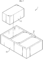
- FIG. 1 is a diagram for illustrating a battery module according to an embodiment of the present disclosure
- FIG. 2 is a side sectional view showing the battery module of FIG. 1
- FIG. 3 is a side sectional view showing the battery module of FIG. 1 according to another embodiment.
- the battery module 10 may include a battery cell assembly 100, a top plate 200, a bottom plate 300, a sensing assembly 400, a side plate 500, and a compression pad 600.
- the battery cell assembly 100 may include a plurality of battery cells 150.
- the plurality of battery cells 150 may be stacked so as to be electrically connected to each other.
- electrode leads 155 of the plurality of battery cells 150 may be electrically connected to the sensing assembly 400, explained later.
- the top plate 200 may cover an upper side of the battery cell assembly 100. To this end, the top plate 200 may have a size and shape to cover the entire upper side of the battery cell assembly 100.
- the bottom plate 300 is disposed opposite to the top plate 200 and may cover a lower side of the battery cell assembly 100.
- the bottom plate 300 may stably support the battery cell assembly 100.
- the sensing assembly 400 is disposed at a front side and a rear side of the top plate 200 and the bottom plate 300 and may cover the front and rear of the battery cell assembly 100.
- the sensing assembly 400 is electrically connected to the battery cell assembly 100 and may sense a voltage or temperature of the battery cell assembly 100. In addition, the sensing assembly 400 may be connected to an external power source or the like.
- the sensing assembly 400 may include a first bus bar unit 410, a second bus bar unit 430, and a sensing wire 450.
- the first bus bar unit 410 is disposed at a front side of the battery cell assembly 100 and may be coupled to a pair of side plates 500, explained later. Here, the first bus bar unit 410 may also be coupled to the top plate 200 and the bottom plate 300 together.
- the first bus bar unit 410 may include a bus bar body 412 and a cover frame 414.
- the bus bar body 412 may be electrically connected to the electrode leads 155 of the battery cells 150 of the battery cell assembly 100. To this end, the bus bar body 412 may have a plurality of bus bars electrically contacted and connected to the electrode leads 155 of the battery cells 155.
- the cover frame 414 may cover the front side of the bus bar body 412.
- the cover frame 414 may form a front surface of the battery module 10.
- the second bus bar unit 430 is disposed to face the first bus bar unit 410 with the battery cell assembly 100 being interposed therebetween and may be coupled to a pair of side plates 500, explained later, at a rear side of the battery cell assembly 100.
- the second bus bar unit 430 may also be coupled to the top plate 200 and the bottom plate 300 together.
- the second bus bar unit 430 may include a bus bar body 432, a cover frame 434, and a control board 436.
- the bus bar body 432 may be electrically connected to the electrode leads 155 of the battery cells 150 of the battery cell assembly 100. To this end, the bus bar body 432 may have a plurality of bus bars electrically contacted and connected to the electrode leads 155 of the battery cells 155.
- the cover frame 434 may cover the rear side of the bus bar body 432.
- the cover frame 434 may form a rear surface of the battery module 10.
- the control board 436 is for controlling the operation of the sensing assembly 400 and may be mounted between the bus bar body 432 and the cover frame 434.
- the control board 436 may be a printed circuit board.
- the sensing wire 450 may connect the first bus bar unit 410 and the second bus bar unit 430.
- the sensing wires 450 may be formed as a flexible printed circuit board and may be provided in a pair.
- the pair of sensing wires 450 may be fitted into the pair of side plates 500, explained later, or into the pair of compression pads 600, explained later. That is, in this embodiment, the pair of sensing wires 450 may be provided at both side surfaces of the battery module 10.
- the side plate 500 is coupled to the top plate 200 and the bottom plate 300 and may be disposed at both side surfaces of the battery cell assembly 100. To this end, the side plate 500 may be provided in a pair.
- the compression pad 600 may be disposed between the pair of side plates 500 and the battery cell assembly 100.
- the compression pad 600 may be provided only in a pair.
- One of the pair of compression pads 600 may be disposed at one of the pair of side plates 500 and one side surface of the battery cell assembly 100.
- the other of the pair of compression pads 600 may be disposed at the other of the pair of side plates 500 and the other side surface of the battery cell assembly 100.
- the compression pads 600 are provided only in a pair, the space efficiency of the battery module 10 may be maximized compared with a conventional structure in which a plurality of compression pads are mounted, and the battery module 10 may be designed in a slim form more easily.
- the pair of compression pads 600 may have a wire placing groove 650.
- the wire placing groove 650 may be formed by a predetermined length along the longitudinal direction of the pair of compression pads 600, and the pair of sensing wires 450 may be placed therein.
- the wire placing groove 650 may have a depth corresponding to the thickness of the pair of sensing wires 450. Accordingly, the pair of sensing wires 450 may not protrude out of the compression pad 600 when being placed in the wire placing groove 650.
- the wire placing groove 650 may also be formed at the pair of side plates 500 as disclosed in FIG. 3 , instead of the pair of compression pads 600. That is, the pair of side plates 500 may have a wire placing groove 550 formed along the longitudinal direction of the pair of sensing wires 450 by a predetermined length so that the pair of sensing wires 450 is placed therein. Also, the depth of the wire placing groove 550 may be correspond to the thickness of the pair of sensing wires 450.
- the space efficiency of the battery module 10 may be improved in the height direction.
- the pair of sensing wires 450 are mounted to both side surfaces of the battery module 10 not to protrude out of the side plate 500 or the compression pad 600, it is possible to secure space efficiency of both side surfaces of the battery module 10.
- FIG. 4 is a diagram for illustrating a battery module according to another embodiment of the present disclosure
- FIG. 5 is a diagram for illustrating a main part of a sensing assembly of the battery module of FIG. 4
- FIG. 6 is a diagram for illustrating a main part of a side plate of the battery module of FIG. 4 .
- the battery module 20 of this embodiment is substantially identical or similar to the battery module 10 of the former embodiment, the identical or similar features will not be explained again, and the following description will focus on different features from the former embodiment.
- the battery module 20 may include a battery cell assembly 100, a top plate 200, a bottom plate 300, a pair of compression pads 600, a sensing assembly 700, and a pair of side plates 800.
- the battery cell assembly 100, the top plate 200, the bottom plate 300 and the pair of compression pads 600 are substantially identical or similar to those of the former embodiment and thus will not described again.
- the sensing assembly 700 may include a sensing wire 750, a first bus bar unit 760 and a second bus bar unit 780.
- the sensing wire 750 is substantially identical or similar to that of the former embodiment and thus will not described again.
- the first bus bar unit 760 may include a bus bar body 762, a cover frame 764, and a coupling pin 768.
- the bus bar body 762 and the cover frame 764 are substantially identical or similar to those of the former embodiment and thus will not described again.
- the coupling pin 768 may couple the first bus bar unit 760 and the pair of side plates 800, explained later, to each other.
- the coupling pin 768 may be provided in plural.
- the plurality of coupling pins 768 are provided at both ends of the first bus bar unit 760 and may be spaced apart from each other by a predetermined distance along the height direction of the first bus bar unit 760.
- the plurality of coupling pins 768 are provided at both side surfaces of the cover frame 764 and may be spaced apart from each other along the height direction of the cover frame 764.
- the second bus bar unit 780 may include a bus bar body 782, a cover frame 784, a control board 786, and a coupling pin 788.
- the bus bar body 782, the cover frame 784 and the control board 786 are substantially identical or similar to those of the former embodiment and thus will not described again.
- the coupling pin 788 may couple the second bus bar unit 780 with the pair of side plates 800, explained later, to each other.
- the coupling pin 788 may be provided in plural.
- the plurality of coupling pins 788 are provided at both ends of the second bus bar unit 780 and may be spaced apart from each other by a predetermined distance along the height direction of the second bus bar unit 780.
- the plurality of coupling pins 788 are provided at both side surfaces of the cover frame 784 and may be spaced apart from each other along the height direction of the cover frame 784.
- the pair of side plates 800 may have a pin insert groove 850 formed therein.
- the coupling pins 768 of the first bus bar unit 760 and the coupling pins 788 of the second bus bar unit 780 may be inserted into the pin insert groove 850.
- the pin insert groove 850 may be provided in plural.
- the plurality of pin insert grooves 850 may be spaced apart from each other by a predetermined distance along the height direction of the pair of side plates 800.
- the sensing assembly 700 and the side plate 800 may be coupled more conveniently by means of the pin insertion structure of the sensing assembly 700 and the side plate 800 without any additional bonding process such as welding.
- FIG. 7 is a diagram for illustrating a battery pack according to an embodiment of the present disclosure.
- a battery pack 1 may include at least one battery module 10 according to the former embodiment and a pack case 50 for packaging the at least one battery module 10.
- the at least one battery module may be the battery module 20 of the former embodiment. It is also possible that the battery module may be provided as a group of the battery module 10 and the battery module 20 of the former embodiments.
- the battery pack 1 may be provided to a vehicle as a fuel source of the vehicle.
- the battery pack 1 may be provided to an electric vehicle, a hybrid vehicle, and various other-type vehicles capable of using the battery pack 1 as a fuel source.
- the battery pack 1 may be provided in other devices, instruments or facilities such as an energy storage system using a secondary battery, in addition to the vehicle.
- the battery pack 1 of this embodiment and devices, instruments or facilities such as a vehicle, which have the battery pack 1 include the battery module 10 as described above, and thus it is possible to implement a battery pack 1 having all the advantages of the battery module 10 described above, or devices, instruments, facilities or the like such as a vehicle, which have the battery pack 1.
- a battery module 10, 20, which may realize a more compact size while further securing a greater space for battery cells 150, a battery pack 1 including the battery module 10, 20, and a vehicle including the battery pack 1.
Landscapes
- Chemical & Material Sciences (AREA)
- Chemical Kinetics & Catalysis (AREA)
- Electrochemistry (AREA)
- General Chemical & Material Sciences (AREA)
- Engineering & Computer Science (AREA)
- Manufacturing & Machinery (AREA)
- Microelectronics & Electronic Packaging (AREA)
- Battery Mounting, Suspending (AREA)
Priority Applications (1)
| Application Number | Priority Date | Filing Date | Title |
|---|---|---|---|
| EP24184816.7A EP4447193B1 (de) | 2018-03-07 | 2019-02-13 | Batteriemodul, batteriepack mit dem batteriemodul und automobil mit dem batteriepack |
Applications Claiming Priority (2)
| Application Number | Priority Date | Filing Date | Title |
|---|---|---|---|
| KR1020180026988A KR102250204B1 (ko) | 2018-03-07 | 2018-03-07 | 배터리 모듈, 이러한 배터리 모듈을 포함하는 배터리 팩 및 이러한 배터리 팩을 포함하는 자동차 |
| PCT/KR2019/001782 WO2019172545A1 (ko) | 2018-03-07 | 2019-02-13 | 배터리 모듈, 이러한 배터리 모듈을 포함하는 배터리 팩 및 이러한 배터리 팩을 포함하는 자동차 |
Related Child Applications (1)
| Application Number | Title | Priority Date | Filing Date |
|---|---|---|---|
| EP24184816.7A Division EP4447193B1 (de) | 2018-03-07 | 2019-02-13 | Batteriemodul, batteriepack mit dem batteriemodul und automobil mit dem batteriepack |
Publications (2)
| Publication Number | Publication Date |
|---|---|
| EP3675223A1 true EP3675223A1 (de) | 2020-07-01 |
| EP3675223A4 EP3675223A4 (de) | 2021-01-13 |
Family
ID=67846210
Family Applications (2)
| Application Number | Title | Priority Date | Filing Date |
|---|---|---|---|
| EP24184816.7A Active EP4447193B1 (de) | 2018-03-07 | 2019-02-13 | Batteriemodul, batteriepack mit dem batteriemodul und automobil mit dem batteriepack |
| EP19763310.0A Pending EP3675223A4 (de) | 2018-03-07 | 2019-02-13 | Batteriemodul, batteriepack mit dem batteriemodul und automobil mit dem batteriepack |
Family Applications Before (1)
| Application Number | Title | Priority Date | Filing Date |
|---|---|---|---|
| EP24184816.7A Active EP4447193B1 (de) | 2018-03-07 | 2019-02-13 | Batteriemodul, batteriepack mit dem batteriemodul und automobil mit dem batteriepack |
Country Status (9)
| Country | Link |
|---|---|
| US (4) | US11522246B2 (de) |
| EP (2) | EP4447193B1 (de) |
| JP (1) | JP7045592B2 (de) |
| KR (1) | KR102250204B1 (de) |
| CN (2) | CN115939649A (de) |
| ES (1) | ES3023216T3 (de) |
| HU (1) | HUE071270T2 (de) |
| PL (1) | PL4447193T3 (de) |
| WO (1) | WO2019172545A1 (de) |
Families Citing this family (18)
| Publication number | Priority date | Publication date | Assignee | Title |
|---|---|---|---|---|
| KR102250204B1 (ko) * | 2018-03-07 | 2021-05-10 | 주식회사 엘지화학 | 배터리 모듈, 이러한 배터리 모듈을 포함하는 배터리 팩 및 이러한 배터리 팩을 포함하는 자동차 |
| KR102378527B1 (ko) * | 2018-12-05 | 2022-03-23 | 주식회사 엘지에너지솔루션 | 전지 모듈 및 그 제조 방법 |
| KR102473336B1 (ko) * | 2019-10-07 | 2022-12-01 | 주식회사 엘지에너지솔루션 | 전지 모듈 및 이를 포함하는 전지팩 |
| KR102481343B1 (ko) * | 2019-10-25 | 2022-12-23 | 주식회사 엘지에너지솔루션 | 전지 모듈 및 이를 포함하는 전지팩 |
| KR102876302B1 (ko) * | 2019-10-25 | 2025-10-23 | 주식회사 엘지에너지솔루션 | 전지 모듈 및 이을 포함하는 전지 팩 |
| KR102890750B1 (ko) * | 2020-01-16 | 2025-11-24 | 주식회사 엘지에너지솔루션 | 전지 모듈 및 이를 포함하는 전지팩 |
| KR102917540B1 (ko) * | 2020-01-21 | 2026-01-23 | 주식회사 엘지에너지솔루션 | 셀 모듈 어셈블리 및 그 제조 방법 |
| KR102754508B1 (ko) * | 2020-03-17 | 2025-01-13 | 주식회사 엘지에너지솔루션 | 전지 모듈 및 이를 포함하는 전지 팩 |
| KR20220000637A (ko) | 2020-06-26 | 2022-01-04 | 주식회사 엘지에너지솔루션 | 전지 모듈 및 이를 포함하는 전지팩 |
| KR20220026790A (ko) * | 2020-08-26 | 2022-03-07 | 주식회사 엘지에너지솔루션 | 전지 모듈 및 이를 포함하는 전지팩 |
| DE212021000361U1 (de) | 2020-10-26 | 2022-12-22 | Lg Energy Solution, Ltd. | Batteriemodul und Batteriepack mit diesem Modul |
| ES2983049T3 (es) | 2020-12-11 | 2024-10-21 | Contemporary Amperex Technology Hong Kong Ltd | Batería, aparato de utilización de energía y método de fabricación de batería |
| KR102834536B1 (ko) * | 2021-01-11 | 2025-07-15 | 주식회사 엘지에너지솔루션 | 팽창완화 유닛을 포함하는 전지 모듈 |
| KR102454069B1 (ko) * | 2021-09-13 | 2022-10-13 | 유진에스엠알시오토모티브테크노 주식회사 | 스웰링 대응구조를 갖는 배터리 모듈 |
| CN117203836A (zh) * | 2021-11-26 | 2023-12-08 | 株式会社Lg新能源 | 电池模块、电池组以及包括电池组的能量存储设备 |
| KR20240041431A (ko) * | 2022-09-23 | 2024-04-01 | 주식회사 엘지에너지솔루션 | 배터리 모듈 및 이를 포함하는 배터리 팩 |
| KR20240153771A (ko) * | 2023-04-17 | 2024-10-24 | 현대자동차주식회사 | 배터리 모듈 어셈블리 |
| KR20240161915A (ko) | 2023-05-06 | 2024-11-13 | 한광현 | 온도 및 압력 변화로부터 셀을 보호하는 배터리 모듈과 이를 구비한 배터리 팩 |
Family Cites Families (31)
| Publication number | Priority date | Publication date | Assignee | Title |
|---|---|---|---|---|
| EP1991880B1 (de) * | 2006-03-06 | 2020-01-08 | LG Chem. Ltd. | Spannungsmessglied und batteriemodul damit |
| WO2008021964A2 (en) * | 2006-08-09 | 2008-02-21 | Black & Decker Inc. | Battery pack and internal component arrangement within the battery pack for cordless power tool system |
| EP2416436B1 (de) * | 2009-04-01 | 2018-02-21 | LG Chem, Ltd. | Spannungserkennungselement und batteriemodul damit |
| KR101126889B1 (ko) | 2010-05-31 | 2012-03-20 | 에스비리모티브 주식회사 | 배터리 팩 |
| JP5932990B2 (ja) * | 2011-06-27 | 2016-06-08 | エルジー・ケム・リミテッド | 電池モジュール及びこれを含む電池アセンブリー |
| US20130115496A1 (en) | 2011-11-07 | 2013-05-09 | Johnson Controls Technology Llc | One-piece housing with plugs for prismatic cell assembly |
| JP2013178894A (ja) | 2012-02-28 | 2013-09-09 | Sanyo Electric Co Ltd | 電源装置 |
| KR20140130357A (ko) * | 2013-04-30 | 2014-11-10 | 타이코에이엠피(유) | 이차전지 팩 |
| KR20150024724A (ko) | 2013-08-27 | 2015-03-09 | 삼성에스디아이 주식회사 | 배터리 팩 |
| KR101707976B1 (ko) * | 2013-10-29 | 2017-02-17 | 주식회사 엘지화학 | 개선된 체결구조를 갖는 센싱 모듈을 구비하는 배터리 모듈 |
| KR102258973B1 (ko) * | 2013-10-31 | 2021-06-02 | 타이코에이엠피 주식회사 | 센싱 블록 및 이를 포함하는 배터리 패키지 |
| JP6281398B2 (ja) | 2014-04-21 | 2018-02-21 | 株式会社豊田自動織機 | 電池モジュール |
| US10230219B2 (en) | 2014-05-29 | 2019-03-12 | Hitachi Automotive Systems, Ltd. | Storage module |
| EP3161899A4 (de) * | 2014-06-30 | 2017-12-27 | Black & Decker Inc. | Batteriepack für schnurlose elektrowerkzeuge |
| KR101679913B1 (ko) * | 2014-08-12 | 2016-11-25 | 현대자동차주식회사 | 배터리 모듈 |
| JP6252464B2 (ja) * | 2014-12-22 | 2017-12-27 | 株式会社オートネットワーク技術研究所 | 蓄電パック |
| KR102308635B1 (ko) | 2015-04-17 | 2021-10-05 | 삼성에스디아이 주식회사 | 배터리 모듈 |
| KR102009443B1 (ko) * | 2015-06-19 | 2019-08-12 | 주식회사 엘지화학 | 카트리지 및 이를 포함하는 전지 모듈 |
| JPWO2017026145A1 (ja) | 2015-08-07 | 2018-03-01 | 株式会社Ihi | 電池モジュール |
| KR102047480B1 (ko) * | 2015-10-30 | 2019-11-21 | 주식회사 엘지화학 | 배터리 모듈 및 이를 포함하는 배터리 팩 |
| KR102047481B1 (ko) | 2015-10-30 | 2019-11-21 | 주식회사 엘지화학 | 배터리 모듈 및 이를 포함하는 배터리 팩 |
| KR102507879B1 (ko) | 2015-11-16 | 2023-03-07 | 삼성에스디아이 주식회사 | 이차 전지 모듈 |
| KR101916720B1 (ko) | 2016-01-05 | 2018-11-08 | 엘지전자 주식회사 | 배터리 모듈 및 그 제조방법, 배터리 모듈을 이용한 전기 자동차 |
| JP2017195018A (ja) | 2016-04-18 | 2017-10-26 | 株式会社豊田自動織機 | 電池パック |
| KR102018721B1 (ko) | 2016-05-31 | 2019-09-09 | 주식회사 엘지화학 | 배터리 모듈 및 이를 포함하는 배터리 팩, 자동차 |
| KR102018301B1 (ko) | 2016-09-01 | 2019-09-04 | 주식회사 엘지화학 | 배터리 모듈 및 그 제조 방법 |
| KR20180026988A (ko) | 2016-09-05 | 2018-03-14 | 전승탁 | 간이 지진계 |
| CN206250254U (zh) | 2016-12-27 | 2017-06-13 | 宁德时代新能源科技股份有限公司 | 电池模组端板组件及电池模组 |
| KR101829350B1 (ko) | 2016-12-30 | 2018-02-14 | 한국단자공업 주식회사 | 배터리모듈용 센싱장치 |
| KR102159347B1 (ko) * | 2017-11-14 | 2020-09-23 | 주식회사 엘지화학 | 배터리 셀 가압형 엔드 플레이트와 확장형 센싱 하우징 구조가 적용된 배터리 모듈 |
| KR102250204B1 (ko) * | 2018-03-07 | 2021-05-10 | 주식회사 엘지화학 | 배터리 모듈, 이러한 배터리 모듈을 포함하는 배터리 팩 및 이러한 배터리 팩을 포함하는 자동차 |
-
2018
- 2018-03-07 KR KR1020180026988A patent/KR102250204B1/ko active Active
-
2019
- 2019-02-13 US US16/629,793 patent/US11522246B2/en active Active
- 2019-02-13 EP EP24184816.7A patent/EP4447193B1/de active Active
- 2019-02-13 PL PL24184816.7T patent/PL4447193T3/pl unknown
- 2019-02-13 EP EP19763310.0A patent/EP3675223A4/de active Pending
- 2019-02-13 WO PCT/KR2019/001782 patent/WO2019172545A1/ko not_active Ceased
- 2019-02-13 CN CN202310080030.7A patent/CN115939649A/zh active Pending
- 2019-02-13 HU HUE24184816A patent/HUE071270T2/hu unknown
- 2019-02-13 ES ES24184816T patent/ES3023216T3/es active Active
- 2019-02-13 CN CN201980003932.2A patent/CN111052439B/zh active Active
- 2019-02-13 JP JP2019571294A patent/JP7045592B2/ja active Active
-
2022
- 2022-11-01 US US17/978,676 patent/US11923562B2/en active Active
-
2024
- 2024-01-02 US US18/402,240 patent/US12261326B2/en active Active
-
2025
- 2025-02-10 US US19/049,602 patent/US20250183487A1/en active Pending
Also Published As
| Publication number | Publication date |
|---|---|
| KR20190106060A (ko) | 2019-09-18 |
| CN115939649A (zh) | 2023-04-07 |
| US20210036277A1 (en) | 2021-02-04 |
| ES3023216T3 (en) | 2025-05-30 |
| US20240195017A1 (en) | 2024-06-13 |
| WO2019172545A1 (ko) | 2019-09-12 |
| US11923562B2 (en) | 2024-03-05 |
| US12261326B2 (en) | 2025-03-25 |
| KR102250204B1 (ko) | 2021-05-10 |
| US20230047201A1 (en) | 2023-02-16 |
| CN111052439A (zh) | 2020-04-21 |
| JP7045592B2 (ja) | 2022-04-01 |
| EP3675223A4 (de) | 2021-01-13 |
| JP2020524888A (ja) | 2020-08-20 |
| HUE071270T2 (hu) | 2025-08-28 |
| EP4447193B1 (de) | 2025-04-02 |
| PL4447193T3 (pl) | 2025-06-09 |
| US20250183487A1 (en) | 2025-06-05 |
| EP4447193A1 (de) | 2024-10-16 |
| US11522246B2 (en) | 2022-12-06 |
| CN111052439B (zh) | 2023-02-17 |
Similar Documents
| Publication | Publication Date | Title |
|---|---|---|
| US11923562B2 (en) | Battery module, battery pack including same battery module, and automobile including same battery pack | |
| EP3836244B1 (de) | Batteriemodul und batteriepack mit dem batteriemodul | |
| EP3675274B1 (de) | Batteriemodul, batteriepack mit dem batteriemodul und fahrzeug mit dem batteriepack | |
| EP3336928B1 (de) | Batteriemodul, batteriepack mit batteriemodul und fahrzeug mit batteriepack | |
| KR101841801B1 (ko) | 엔드 플레이트를 결합시키는 부싱을 포함한 배터리 팩 | |
| EP3567669B1 (de) | Batteriemodul, batteriepack mit dem batteriemodul und fahrzeug mit dem batteriepack | |
| US11158895B2 (en) | Battery module, battery pack including battery module, and vehicle including battery pack | |
| EP3675239A1 (de) | Batteriemodul sowie batteriepack und automobil damit | |
| EP3644401B1 (de) | Batteriemodul sowie batteriepack und fahrzeug damit | |
| US11456502B2 (en) | Battery module, battery pack comprising same battery module, and vehicle comprising same battery pack | |
| KR20150142790A (ko) | 스웰링 현상에 의한 배터리 모듈의 외형 변화를 방지할 수 있는 배터리 모듈 어셈블리용 엔드 플레이트 및 이를 포함하는 배터리 팩 | |
| CN114080726B (zh) | 单体模块组件和制造该单体模块组件的方法 | |
| CN108140797A (zh) | 包括一体式弹簧或柔性垫的电池端子 | |
| EP4027448A1 (de) | Batteriemodul, batteriepack mit batteriemodul und fahrzeug |
Legal Events
| Date | Code | Title | Description |
|---|---|---|---|
| STAA | Information on the status of an ep patent application or granted ep patent |
Free format text: STATUS: THE INTERNATIONAL PUBLICATION HAS BEEN MADE |
|
| PUAI | Public reference made under article 153(3) epc to a published international application that has entered the european phase |
Free format text: ORIGINAL CODE: 0009012 |
|
| STAA | Information on the status of an ep patent application or granted ep patent |
Free format text: STATUS: REQUEST FOR EXAMINATION WAS MADE |
|
| 17P | Request for examination filed |
Effective date: 20200325 |
|
| AK | Designated contracting states |
Kind code of ref document: A1 Designated state(s): AL AT BE BG CH CY CZ DE DK EE ES FI FR GB GR HR HU IE IS IT LI LT LU LV MC MK MT NL NO PL PT RO RS SE SI SK SM TR |
|
| AX | Request for extension of the european patent |
Extension state: BA ME |
|
| A4 | Supplementary search report drawn up and despatched |
Effective date: 20201211 |
|
| RIC1 | Information provided on ipc code assigned before grant |
Ipc: H01M 2/02 20060101ALI20201207BHEP Ipc: H01M 2/20 20060101ALI20201207BHEP Ipc: H01M 10/48 20060101ALI20201207BHEP Ipc: H01M 2/10 20060101AFI20201207BHEP Ipc: H01M 10/42 20060101ALI20201207BHEP |
|
| DAV | Request for validation of the european patent (deleted) | ||
| DAX | Request for extension of the european patent (deleted) | ||
| RAP1 | Party data changed (applicant data changed or rights of an application transferred) |
Owner name: LG ENERGY SOLUTION LTD. |
|
| RAP3 | Party data changed (applicant data changed or rights of an application transferred) |
Owner name: LG ENERGY SOLUTION, LTD. |
|
| STAA | Information on the status of an ep patent application or granted ep patent |
Free format text: STATUS: EXAMINATION IS IN PROGRESS |
|
| 17Q | First examination report despatched |
Effective date: 20221201 |