EP3675313A2 - Verfahren und vorrichtung zur steuerung des ladevorgangs auf der basis des batteriestatus - Google Patents
Verfahren und vorrichtung zur steuerung des ladevorgangs auf der basis des batteriestatus Download PDFInfo
- Publication number
- EP3675313A2 EP3675313A2 EP18857154.1A EP18857154A EP3675313A2 EP 3675313 A2 EP3675313 A2 EP 3675313A2 EP 18857154 A EP18857154 A EP 18857154A EP 3675313 A2 EP3675313 A2 EP 3675313A2
- Authority
- EP
- European Patent Office
- Prior art keywords
- battery
- voltage
- charging
- state
- electronic device
- Prior art date
- Legal status (The legal status is an assumption and is not a legal conclusion. Google has not performed a legal analysis and makes no representation as to the accuracy of the status listed.)
- Granted
Links
Images






Classifications
-
- H—ELECTRICITY
- H02—GENERATION; CONVERSION OR DISTRIBUTION OF ELECTRIC POWER
- H02J—ELECTRIC POWER NETWORKS; CIRCUIT ARRANGEMENTS OR SYSTEMS FOR SUPPLYING OR DISTRIBUTING ELECTRIC POWER; SYSTEMS FOR STORING ELECTRIC ENERGY
- H02J7/00—Circuit arrangements for charging or discharging batteries or for supplying loads from batteries
- H02J7/90—Regulation of charging or discharging current or voltage
- H02J7/96—Regulation of charging or discharging current or voltage in response to battery voltage
-
- G—PHYSICS
- G01—MEASURING; TESTING
- G01R—MEASURING ELECTRIC VARIABLES; MEASURING MAGNETIC VARIABLES
- G01R31/00—Arrangements for testing electric properties; Arrangements for locating electric faults; Arrangements for electrical testing characterised by what is being tested not provided for elsewhere
- G01R31/36—Arrangements for testing, measuring or monitoring the electrical condition of accumulators or electric batteries, e.g. capacity or state of charge [SoC]
-
- G—PHYSICS
- G01—MEASURING; TESTING
- G01R—MEASURING ELECTRIC VARIABLES; MEASURING MAGNETIC VARIABLES
- G01R31/00—Arrangements for testing electric properties; Arrangements for locating electric faults; Arrangements for electrical testing characterised by what is being tested not provided for elsewhere
- G01R31/36—Arrangements for testing, measuring or monitoring the electrical condition of accumulators or electric batteries, e.g. capacity or state of charge [SoC]
- G01R31/382—Arrangements for monitoring battery or accumulator variables, e.g. SoC
- G01R31/3835—Arrangements for monitoring battery or accumulator variables, e.g. SoC involving only voltage measurements
-
- G—PHYSICS
- G01—MEASURING; TESTING
- G01R—MEASURING ELECTRIC VARIABLES; MEASURING MAGNETIC VARIABLES
- G01R31/00—Arrangements for testing electric properties; Arrangements for locating electric faults; Arrangements for electrical testing characterised by what is being tested not provided for elsewhere
- G01R31/36—Arrangements for testing, measuring or monitoring the electrical condition of accumulators or electric batteries, e.g. capacity or state of charge [SoC]
- G01R31/392—Determining battery ageing or deterioration, e.g. state of health
-
- H—ELECTRICITY
- H02—GENERATION; CONVERSION OR DISTRIBUTION OF ELECTRIC POWER
- H02J—ELECTRIC POWER NETWORKS; CIRCUIT ARRANGEMENTS OR SYSTEMS FOR SUPPLYING OR DISTRIBUTING ELECTRIC POWER; SYSTEMS FOR STORING ELECTRIC ENERGY
- H02J7/00—Circuit arrangements for charging or discharging batteries or for supplying loads from batteries
- H02J7/60—Circuit arrangements for charging or discharging batteries or for supplying loads from batteries including safety or protection arrangements
-
- H—ELECTRICITY
- H02—GENERATION; CONVERSION OR DISTRIBUTION OF ELECTRIC POWER
- H02J—ELECTRIC POWER NETWORKS; CIRCUIT ARRANGEMENTS OR SYSTEMS FOR SUPPLYING OR DISTRIBUTING ELECTRIC POWER; SYSTEMS FOR STORING ELECTRIC ENERGY
- H02J7/00—Circuit arrangements for charging or discharging batteries or for supplying loads from batteries
- H02J7/80—Circuit arrangements for charging or discharging batteries or for supplying loads from batteries including monitoring or indicating arrangements
- H02J7/82—Control of state of charge [SOC]
-
- H—ELECTRICITY
- H02—GENERATION; CONVERSION OR DISTRIBUTION OF ELECTRIC POWER
- H02J—ELECTRIC POWER NETWORKS; CIRCUIT ARRANGEMENTS OR SYSTEMS FOR SUPPLYING OR DISTRIBUTING ELECTRIC POWER; SYSTEMS FOR STORING ELECTRIC ENERGY
- H02J7/00—Circuit arrangements for charging or discharging batteries or for supplying loads from batteries
- H02J7/90—Regulation of charging or discharging current or voltage
- H02J7/94—Regulation of charging or discharging current or voltage in response to battery current
- H02J7/953—Regulation of charging or discharging current or voltage in response to battery current in response to charge current gradient
-
- H—ELECTRICITY
- H04—ELECTRIC COMMUNICATION TECHNIQUE
- H04M—TELEPHONIC COMMUNICATION
- H04M1/00—Substation equipment, e.g. for use by subscribers
- H04M1/02—Constructional features of telephone sets
- H04M1/0202—Portable telephone sets, e.g. cordless phones, mobile phones or bar type handsets
- H04M1/026—Details of the structure or mounting of specific components
- H04M1/0262—Details of the structure or mounting of specific components for a battery compartment
-
- H—ELECTRICITY
- H04—ELECTRIC COMMUNICATION TECHNIQUE
- H04M—TELEPHONIC COMMUNICATION
- H04M1/00—Substation equipment, e.g. for use by subscribers
- H04M1/72—Mobile telephones; Cordless telephones, i.e. devices for establishing wireless links to base stations without route selection
- H04M1/724—User interfaces specially adapted for cordless or mobile telephones
- H04M1/72403—User interfaces specially adapted for cordless or mobile telephones with means for local support of applications that increase the functionality
- H04M1/72409—User interfaces specially adapted for cordless or mobile telephones with means for local support of applications that increase the functionality by interfacing with external accessories
-
- H—ELECTRICITY
- H04—ELECTRIC COMMUNICATION TECHNIQUE
- H04M—TELEPHONIC COMMUNICATION
- H04M1/00—Substation equipment, e.g. for use by subscribers
- H04M1/72—Mobile telephones; Cordless telephones, i.e. devices for establishing wireless links to base stations without route selection
- H04M1/724—User interfaces specially adapted for cordless or mobile telephones
- H04M1/72448—User interfaces specially adapted for cordless or mobile telephones with means for adapting the functionality of the device according to specific conditions
- H04M1/72454—User interfaces specially adapted for cordless or mobile telephones with means for adapting the functionality of the device according to specific conditions according to context-related or environment-related conditions
-
- H—ELECTRICITY
- H02—GENERATION; CONVERSION OR DISTRIBUTION OF ELECTRIC POWER
- H02J—ELECTRIC POWER NETWORKS; CIRCUIT ARRANGEMENTS OR SYSTEMS FOR SUPPLYING OR DISTRIBUTING ELECTRIC POWER; SYSTEMS FOR STORING ELECTRIC ENERGY
- H02J7/00—Circuit arrangements for charging or discharging batteries or for supplying loads from batteries
- H02J7/90—Regulation of charging or discharging current or voltage
- H02J7/96—Regulation of charging or discharging current or voltage in response to battery voltage
- H02J7/963—Regulation of charging or discharging current or voltage in response to battery voltage in response to battery voltage gradient
Definitions
- the present disclosure relates to a technology for charging a battery included in an electronic device by using a power received from an external power source of the electronic device.
- the portable electronic device uses a battery, which is embedded in the electronic device or is detachable, as a power supply source.
- a technology for increasing the capacity of the battery is being developed; however, the capacity of the battery is restrictive, and a user needs to charge the battery by using a charging device in the case where the remaining capacity of the battery is insufficient.
- An electronic device which uses the battery, such as a smartphone may charge the battery by using the charging device.
- the charging device may be placed outside the electronic device and may supply a power to the electronic device through a connector.
- the electronic device may control charging based on a voltage of the battery.
- an inexact battery voltage may be measured.
- the electronic device may control charging based on the inexact battery voltage. This causes incomplete charging, charging delay, and/or overheating of the electronic device.
- a charging and discharging characteristic of the battery may be changed. In this case, specified battery charging control parameters may not correspond to a present characteristic of the battery.
- the electronic device may control charging based only on a voltage of the battery. For example, the electronic device may selectively perform constant current (CC) charging or constant voltage (CV) charging based on the voltage of the battery.
- CC constant current
- CV constant voltage
- the issues such as incomplete charging, charging delay, and/or overheating of the electronic device, cannot be solved through the charging control only based on the battery voltage.
- an aspect of the present disclosure is to provide an apparatus and a method which may detect a non-ideal charging situation and may charge a battery depending on battery status.
- an electronic device may include a battery, a first detection circuit that detects a voltage of the battery, a charging circuit that charges the battery in a constant current state or a constant voltage state based on the voltage of the battery, a second detection circuit that detects an output voltage of the charging circuit, and a processor.
- the processor may verify the voltage of the battery by using the first detection circuit and the output voltage by using the second detection circuit, while the battery is charged in the constant current state, and may determine a state of the battery based at least on the voltage of the battery and the output voltage.
- an electronic device may a battery, a first detection circuit that detects a voltage of the battery, a charging circuit that charges the battery in a constant current state or a constant voltage state based on the voltage of the battery, a second detection circuit that detects an output voltage of the charging circuit, a display, and a processor.
- the processor may periodically verify the voltage of the battery and the output voltage by using the first detection circuit and the second detection circuit, respectively, while the battery is charged in the constant current state, and may provide information about a charging state of the battery through the display based on at least one of a difference between the voltage of the battery and the output voltage, the change in the voltage of the battery periodically verified, or the change in the output voltage periodically verified.
- an electronic device may include a battery, a first detection circuit that detects a voltage of the battery, a charging circuit that charges the battery in a constant current state or a constant voltage state based on the voltage of the battery, a second detection circuit that detects an output voltage of the charging circuit, and a processor.
- the processor is may verify the voltage of the battery and the output voltage by using the first detection circuit and the second detection circuit, respectively, while the battery is charged in the constant current state, may charge the battery in the constant current state or the constant voltage state depending on a first reference by using the charging circuit, when a difference between the output voltage and the battery voltage is not greater than a specified value, and may charge the battery in the constant current state or the constant voltage state depending on a second reference different from the first reference by using the charging circuit, when the difference between the output voltage and the battery voltage exceeds the specified value.
- the first reference may include a first battery voltage value.
- abnormal charging of an electronic device may be previously prevented.
- more efficient charging may be performed by supplying an appropriate power to a battery of the electronic device.
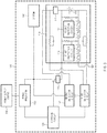
- FIG. 1 is a block diagram of an electronic device according to an embodiment.
- the electronic device 100 may include a battery 110, a processor 120, a charging circuit 130, and a detection circuit 140. Also, in an embodiment, the electronic device 100 may include at least one output circuit. The at least one output circuit may provide, for example, a visual, auditory, and/or tactile output. In an embodiment, the electronic device 100 may include a display 180 as the at least one output circuit.
- the battery 110 may include one or more charging cells. Also, the battery 110 may supply the power to any other components of the electronic device 100. In an embodiment, the battery 110 may further include various other electronic elements (e.g., a protection circuit module (or a battery protection circuit)). According to various embodiments, the battery 110 may be detachable from the electronic device 100.
- a protection circuit module or a battery protection circuit
- the processor 120 may control other components (e.g., the battery 110, the charging circuit 130, the detection circuit 140, the display 180, and/or any other components (not illustrated)) of the electronic device 100.
- the processor 120 may control other components (e.g., the battery 110, the charging circuit 130, the detection circuit 140, the display 180, and/or any other components (not illustrated)) of the electronic device 100.
- the charging circuit 130 may control an output power (e.g., an output voltage and/or an output current) of the charging circuit 130 based on a voltage of the battery 110. Also, the charging circuit 130 may be controlled by the processor 120 of the electronic device 100.
- an output power e.g., an output voltage and/or an output current
- the detection circuit 140 may measure the voltage of the battery 110.
- the detection circuit 140 may detect the voltage of the battery 110 by measuring a voltage across an anode and a cathode of the battery 110.
- the detection circuit 140 may detect the voltage of the battery 110 periodically or randomly.
- the detection circuit 140 may provide the detected voltage to the charging circuit 130 and/or the processor 120.
- the detection circuit 140 may detect an output voltage of the charging circuit 130 periodically or randomly. Also, the detection circuit 140 may provide the detected voltage to the charging circuit 130 and/or the processor 120.
- the detection circuit 140 may detect a charging amount (e.g., a state of charging (SoC)) of the battery 110 periodically or randomly. Also, the detection circuit 140 may provide the detected charging amount to the charging circuit 130 and/or the processor 120.
- SoC state of charging
- the detection circuit 140 may detect the voltage of the battery 110, the charging amount of the battery 110, and/or the output voltage of the charging circuit 130 periodically or in response to a request.
- the voltage of the battery 110, the charging amount of the battery 110, and/or the output voltage of the charging circuit 130 may be detected at the same time or at different times.
- the detection circuit 140 may provide the processor 120 and/or the charging circuit 130 with information about the voltage of the battery 110, the charging amount of the battery 110, and/or the output voltage of the charging circuit 130 periodically or in response to a request.
- a switch to a constant voltage charging state may be determined based on the voltage of the battery 110.
- an abnormal charging situation may happen due to a change in an internal and/or external impedance of the battery 110.
- a constant current charging state may be switched to the constant voltage charging state due to a recognition error associated with the voltage of the battery 110.
- the processor 120 may obtain or verify the voltage of the battery 110 and the output voltage of the charging circuit 130 by using the detection circuit 140. For example, the processor 120 may obtain or verify the voltage of the battery 110 and the output voltage of the charging circuit 130 at a specified time interval.
- a state of the battery 110 may be defined based on the voltage of the battery 110 and the output voltage of the charging circuit 130.
- the processor 120 may determine the state of the battery 110 based on the voltage of the battery 110 and the output voltage of the charging circuit 130.
- the state of the battery 110 may be determined as a normal charging state or an abnormal charging state based at least on a difference between the voltage of the battery 110 and the output voltage of the charging circuit 130.
- the state of the battery 110 may be referenced as the normal charging state.
- the state of the battery 110 may be referenced as the abnormal charging state.
- the electronic device 100 may determine the state of the battery 110 based on at least one of a change in the voltage of the battery 110 or a change in the output voltage of the charging circuit 130 verified/obtained at the specified time interval.
- the change in the voltage of the battery 110 or the change in the output voltage of the charging circuit 130 may include at least one of a difference between a previously verified value and a presently verified value, a rate of change per hour, or a change in an average in each time interval.
- the processor 120 may determine the state of the battery 110 by comparing at least one of the change in the voltage of the battery 110 or the change in the output voltage of the charging circuit 130 with a specified second value.
- the processor 120 may determine the state of the battery 110 as the normal charging state when the change in the voltage of the battery 110 is within a threshold range or a threshold ratio from the specified second value, and may determine the state of the battery 110 as the abnormal charging state when the change in the voltage of the battery 110 exceeds the threshold range or the threshold ratio from the specified second value. In an embodiment, the processor 120 may determine the state of the battery 110 as the normal charging state when the change in the output voltage of the charging circuit 130 is within the threshold range or the threshold ratio from the specified second value, and may determine the state of the battery 110 as the abnormal charging state when the change in the output voltage of the charging circuit 130 exceeds the threshold range or the threshold ratio from the specified second value.
- the processor 120 may determine the state of the battery 110 as the normal charging state when the changes in the voltage of the battery 110 and the output voltage of the charging circuit 130 are within the threshold range or the threshold ratio from the specified second value, and may determine the state of the battery 110 as an abnormal charging state when the changes in the voltage of the battery 110 and the output voltage of the charging circuit 130 exceed the threshold range or the threshold ratio from the specified second value.
- the processor 120 may determine the state of the battery 110 by comparing the change in the voltage of the battery 110 and/or the change in the output voltage of the charging circuit 130 with a specified second range.
- the threshold range or the threshold ratio from the specified second value of the above-described embodiment may be defined as the specified second range.
- the change in the voltage of the battery 110 or the change in the output voltage of the charging circuit 130 may be associated with a present charging amount of the battery 110.
- the specified second value and/or the specified second range may be a value associated with a charging amount of the battery 110.
- the processor 120 may determine the state of the battery 110 by comparing the specified second value and/or the specified second range associated with the charging amount of the battery 110 with the change in the voltage of the battery 110 or the change in the output voltage of the charging circuit 130.
- the processor 120 may charge the battery 110 in the constant current state or in a constant voltage state based on a specified voltage. For example, in the case where the voltage of the battery 110 is not smaller than the specified value, the processor 120 may charge the battery 110 in the constant voltage state. Also, for example, in the case where the voltage of the battery 110 is smaller than the specified value, the processor 120 may charge the battery 110 in the constant current state.
- the processor 120 may charge the battery 110 in the constant current state or in the constant voltage state based on a reference different than in the case of the normal charging state. In an embodiment, the processor 120 may determine whether to perform a constant voltage charging operation in the case of the normal charging state by comparing the battery voltage and/or the output voltage of the charging circuit 130 with a specified third value, and may determine whether to perform a constant voltage charging operation in the case of the abnormal charging state by comparing the battery voltage and/or the output voltage of the charging circuit 130 with a specified fourth value. The specified fourth value may be set to a value which is different from the specified third value.
- the processor 120 may charge the battery 110 in the constant voltage state regardless of a voltage value of the battery 110. In an embodiment, in the case where the state of the battery 110 is the abnormal charging state, the processor 120 may charge the battery 110 with a current, the level of which is lower than in the normal charging state. In an embodiment, in the case where the state of the battery 110 is the abnormal charging state, the processor 120 may complete charging based on the voltage of the battery 110, which is different from a voltage of the battery 110 in the normal charging state. For example, the processor 120 may complete or interrupt charging at the voltage of the battery 110, which is lower than in the normal charging state. Also, in an embodiment, in the case where the abnormal charging state is determined, the processor 120 may interrupt the charging of the battery 110.
- the processor 120 may determine a cause of the abnormal charging state.
- the detection circuit 140 may detect (or measure) the internal impedance of the battery 110.
- the processor 120 may determine the cause of the abnormal charging state based on a difference between the voltage of the battery 110 and the output voltage of the charging circuit 130, a change in the voltage of the battery 110, a change in the output voltage of the charging circuit 130, and/or an internal impedance of the battery 110.
- the processor 120 may determine that the cause of the abnormal charging state is the internal impedance of the battery 110.
- the processor 120 may determine that the cause of the abnormal charging state is the external impedance of the battery 110.
- the processor 120 may provide information about the state of the battery 110 by using the above-described at least one output circuit (e.g., the display 180).
- the information about the state of the battery 110 may include information indicating at least one of the abnormal charging state, a cause of the abnormal charging state, or an instruction corresponding to the abnormal charging state.
- the information about the state of the battery 110 may be provided a visual, auditory, and/or tactile notification.
- the processor 120 may train a value for determining the state of the battery 110 and/or a value for controlling a constant voltage charging operation of the battery 110. For example, while a charging operation is performed as much as the specified number of times, the processor 120 may record a parameter associated with a charging control of the battery 110.
- the parameter associated with the charging control of the battery 110 may include the voltage of the battery 110, the output voltage of the charging circuit 130, a difference between the voltage of the battery 110 and the output voltage of the charging circuit 130, a change in the voltage of the battery 110, and/or a length of a constant voltage charging switching time according to a charging amount.
- the processor 120 may update the value for determining the state of the battery 110 and/or the value for controlling a constant voltage charging operation of the battery 110.
- the value for determining the state of the battery 110 and/or the value for controlling a constant voltage charging operation of the battery 110 may be a value which is updated based at least on a previously verified parameter associated with a charging control.
- FIG. 2 is a view illustrating a configuration of an electronic device according to an embodiment.
- the electronic device 100 may include a power regulator 150, the charging circuit 130, the detection circuit 140, the battery 110, and a system 160.
- the system 160 may include any other components of the electronic device 100.
- the system 160 may include any other components (e.g., at least one of the remaining components of an electronic device 1201 other than the battery 1289 and the power management module 1288 to be described with reference to FIG. 12 ) of the electronic device 100 including a processor (e.g., the processor 120 of FIG. 1 ).
- a power supply source 200 may supply a power to the electronic device 100 through a connector on the outside of the electronic device 100.
- the power supply source 200 may wirelessly supply the power to the electronic device 100.
- the power regulator 150 may control the power received from the power supply source 200 under control of the charging circuit 130.
- the power regulator 150 may include a DC-DC converter (e.g., a buck-booster converter).
- the battery 110 may include a battery cell 111, a first protection circuit 113, a second protection circuit 114, a plurality of switches, and a plurality of electronic elements.
- One battery cell 111 is illustrated in FIG. 2 .
- the battery 110 may include one or more cells.
- the first protection circuit 113 and the second protection circuit 114 may prevent overcharging and over-discharging of a related cell (e.g., the battery cell 111).
- the battery 110 may include at least one protection circuit.
- the configuration of the battery 110 of FIG. 2 is exemplary.
- the battery 110 may further include any other components not illustrated in FIG. 2 .
- a first impedance 171 indicates an impedance corresponding to a result of modeling the outside of the battery 110
- a second impedance 172 indicates an impedance corresponding to a result of modeling the inside of the battery 110.
- the first impedance 171 corresponds to an abnormal impedance between the charging circuit 130 and the battery 110.
- the first impedance 171 may increase due to an internal or external factor of the electronic device 100.
- the first impedance 171 may be increased.
- the first impedance 171 may be increased when parts of the electronic device 100 are abnormally installed.
- the second impedance 172 corresponds to an abnormal impedance which may occur within the battery 110.
- the second impedance 172 in the battery 110 may be increased by the degradation of performance due to the iteration of charging and discharging of the battery 110 or an external factor.
- the detection circuit 140 may detect the output voltage of the charging circuit 130, the voltage of the battery 110, and/or a charging amount of the battery 110.
- the detection circuit 140 may detect the second impedance 172 in the battery 110.
- the detection circuit 140 may detect the second impedance 172 in the battery 110 by detecting (or measuring) a voltage and a current of the battery 110.
- the embodiment is illustrated in FIG. 2 as the detection circuit 140 is implemented with one component, but the detection circuit 140 may be implemented with a plurality of circuits.
- FIG. 3 is a view illustrating a configuration of an electronic device according to another embodiment.
- a first detection circuit 141 and a second detection circuit 142 corresponds to the detection circuit 140 of FIG. 2 .
- the first detection circuit 141 may detect a voltage Vp of the battery 110 periodically or randomly.
- the first detection circuit 141 may detect a charging amount of the battery 110.
- the second detection circuit 142 may detect an output voltage of the charging circuit 130 periodically or randomly. That is, the second detection circuit 142 may detect a voltage which is applied to the system 160.
- a battery voltage and a system voltage may be measured at the same time or at different times.
- the first detection circuit 141 and the second detection circuit 142 may provide the charging circuit 130 and/or the processor 120 with information including the battery voltage and/or the system voltage periodically or in response to a request.
- the second detection circuit 142 may detect the second impedance 172 in the battery 110.
- the second detection circuit 142 may detect the second impedance 172 in the battery 110 by using a voltage and a current of the battery 110.
- the second detection circuit 142 may provide information about the second detection circuit 142 to the charging circuit 130 and/or the processor 120 periodically or in response to a request.
- a battery voltage may correspond to the voltage of the battery 110 detected by the detection circuit 140
- a charging voltage may correspond to a voltage output from the charging circuit 130
- a charging current may correspond to a current output from the charging circuit 130.
- FIG. 4 is a view illustrating a battery voltage, a charging voltage, and a charging current in a normal charging situation, according to an embodiment.
- a battery voltage is increased until a time t1.
- a charging current of a maximum value may be relatively uniformly maintained for the purpose of charging the battery 110 quickly.
- a time interval before the time t1 may be referenced as a constant current charging interval.
- the charging current decreases; in contrast, the battery voltage may be maintained relatively uniformly.
- an interval after the time t1 may be referenced as a constant voltage charging interval.
- the charging circuit 130 may switch a charging state from the constant current charging state to the constant voltage charging state.
- the charging circuit 130 may perform constant current charging and constant voltage charging under control of the processor 120.
- An electronic element, an integrated circuit, and/or line loss between the charging circuit 130 and the detection circuit 140 may cause an impedance. Since a maximum charging current is maintained in the constant current charging interval, as illustrated in FIG. 4 , a difference between the charging voltage and the battery voltage is maximized. Also, the difference between the charging voltage and the battery voltage is gradually decreased as constant voltage charging is made.
- FIG. 5 is a view illustrating a charging state and a charging current in a normal charging situation, according to an embodiment.
- a charging state may be changed from the constant current charging state to the constant voltage charging state at a time t1.
- a state of charging (SoC) of the battery 110 is approximately 79.5% when the charging state is changed from the constant current charging state to the constant voltage charging state. That is, in a normal charging situation, since the capacity of the battery 110 is charged to approximately 80%, a decrease of the constant current charging interval may cause a delay of a time when charging is completed.
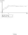
- FIG. 6A is a view illustrating a battery voltage and a system voltage in a normal charging situation according to an embodiment.
- the battery 110 may be charged up to approximately 80% at the time t1. Also, in the normal charging situation, a difference between the system voltage and the battery voltage may be maintained within approximately 10% of the output voltage of the charging circuit 130. Also, for example, a length of a constant current charging interval from a start charging time to the time t1 may be approximately 57 minutes. However, an abnormal charging situation may be caused due to a reason to be described below.
- FIG. 6B is a view illustrating an abnormal charging situation according to one exemplification.
- FIG. 6B is illustrated by the same scale as FIG. 6A .
- an increase in the external impedance (e.g., the first impedance 171) of the battery 110 may cause an abnormal charging situation.
- the increase in the external impedance (e.g., the first impedance 171) of the battery 110 may make a difference between the battery voltage and the charging voltage greater.
- a charging state may be switched from the constant current charging state to the constant voltage charging state.
- a difference between the charging voltage and the battery voltage may correspond to approximately 40% of the output voltage of the charging circuit 130.
- a length of a constant current charging interval may be approximately 57 minutes. Accordingly, in the abnormal charging situation of FIG. 6B , the charging voltage may be greatly increased.
- the increase in the charging voltage may cause abnormal heating and failure of the electronic device 100.
- a charging time may be increased due to the external impedance.
- the abnormal charging state may be detected.
- the processor 120 may control charging of the battery 110, depending on the above-described embodiments, for the purpose of coping with the abnormal charging state. Also, the processor 120 may provide information about the abnormal charging state, depending on the above-described embodiments. Also, as will be described with reference to FIG. 6C , an increase in the internal impedance of the battery 110 may cause the abnormal charging state.
- FIG. 6C is a view illustrating an abnormal charging situation according to another exemplification.
- FIG. 6C is illustrated by the same scale as FIG. 6A .
- an increase in the internal impedance (e.g., the second impedance 172) of the battery 110 may cause an abnormal charging situation.
- the battery voltage may be very quickly increased due to the increase in the internal impedance of the battery 110.
- a charging state may be switched from the constant current charging state to the constant voltage charging state at a time t3.
- a constant current charging interval in an abnormal charging situation of FIG. 6C may be short compared to a normal charging situation of FIG. 6A .
- FIG. 1 in the case of FIG.
- a length of a constant current charging interval may be approximately 30 minutes. Accordingly, even though a charging state of the battery 110 is low, a charging state may be changed to a constant voltage charging state. This may cause an increase in a charging time of the battery 110.
- the abnormal charging state may be detected based on a change in the battery voltage and/or a change in the charging voltage.
- a constant voltage charging switching time is shorter than a switching time of a normal charging situation.
- the abnormal charging state may be detected based on the constant voltage charging switching time.
- a charging amount of the battery 110 at the constant voltage charging switching time t3 is lower than in a normal charging situation.
- the abnormal charging state may be detected based on the battery voltage and the charging amount of the battery 110.
- the processor 120 may control charging of the battery 110, depending on the above-described embodiments, for the purpose of coping with the abnormal charging state. Also, the processor 120 may provide information about the abnormal charging state, depending on the above-described embodiments.
- FIGS. 7A , 7B , and 7C have reference points t1 and t2 on the same time axis.
- FIG. 7A is a view illustrating a charging state for each interval according to one exemplification.
- FIG. 7A is illustrated as a constant current charging interval of FIG. 6A is expanded two times on a time axis.
- rates of change of the battery voltage and the charging voltage in a normal charging situation are illustrated for each interval (for respective first and second intervals).
- FIG. 7B is a view illustrating a charging state for each interval according to another exemplification.
- an abnormal charging situation occurs due to an increase in the external impedance of the battery 110.
- rates of change in the battery voltage and the charging voltage for each interval is similar to rates of change in a normal charging situation.
- a difference between the battery voltage and the charging voltage is greater than in the normal charging situation.
- an abnormal charging situation may be determined based on a difference between the battery voltage and the charging voltage.
- the processor 120 may determine a cause of the abnormal charging situation based on the difference between the battery voltage and the charging voltage.
- FIG. 7C is a view illustrating a charging state for each interval according to another exemplification.
- an abnormal charging situation occurs due to an increase in the internal impedance of the battery 110.
- rates of change of the battery voltage and the charging voltage in the first interval is higher than in a normal charging situation.
- rates of change of the battery voltage and the charging voltage in the first interval are lower than in a normal charging situation.
- an abnormal charging situation may be determined by detecting changes in the battery voltage and the charging voltage at a specified time interval.
- the processor 120 may determine a cause of the abnormal charging situation based on the change in the battery voltage and/or the charging voltage.
- the charging state and the constant voltage charging operation of the battery 110 may be controlled based on various references.
- the above-described references may be changed by various causes such as degradation of the battery 110 and the electronic device 100. Accordingly, in an embodiment, the references may be trained to cope with the degradation of the battery 110 and the electronic device 100.
- FIG. 8 is a flowchart illustrating a battery status determining method according to various embodiments.
- the electronic device 100 may charge the battery 110 in the constant current state.
- the electronic device 100 may perform constant current charging based on a battery voltage.
- the electronic device 100 may charge the battery 110 in the constant current state.
- the electronic device 100 may verify the battery voltage and an output voltage of the charging circuit 130.
- the electronic device 100 may verify the battery voltage and the output voltage of the charging circuit 130 by using the detection circuit 140.
- the electronic device 100 may verify the battery voltage and the output voltage of the charging circuit 130 by using the first detection circuit 141 and the second detection circuit 142.
- the electronic device 100 may perform training based on the battery voltage and/or the output voltage of the charging circuit 130.
- the electronic device 100 may store a training value.
- the training value may include a difference between the battery voltage and the output voltage of the charging circuit 130, a length of a constant current charging interval, a rate of change of the battery voltage, or a rate of change of the impedance of the battery 110 and/or the output voltage of the charging circuit 130.
- the difference between the battery voltage and the output voltage of the charging circuit 130 may be stored with regard to a specified charging amount of the battery 110.
- the length of the constant current charging interval may be stored together with a charging amount of the battery 110 when a constant current charging operation starts and a charging amount of the battery 110 when the constant current charging operation ends.
- the length of the constant current charging interval may be a time taken to arrive at a battery charging amount of a second value from a battery charging amount of a first value or may be a time from a time at which a battery charging amount corresponds to a third value to a time at which the constant current charging operation ends.
- the rate of change of the battery voltage and/or the rate of change of the output voltage of the charging circuit 130 may be stored by accumulating respective voltage values at a specified time interval.
- the rate of change of the battery voltage and/or the rate of change of the output voltage of the charging circuit 130 may be stored as a difference between a previously detected value and a presently detected value.
- the electronic device 100 may store the rate of change of the battery voltage and/or the rate of change of the output voltage of the charging circuit 130 in each of a plurality of time intervals.
- a length of each of the plurality of time intervals may be trained depending on the rate of change of the battery voltage and/or the rate of change of the output voltage of the charging circuit 130.
- the time interval may be changed to a next time interval.
- the electronic device 100 may store the above-described training value at least once or more. For example, in the case where the constant current charging operation is completed once, the training operation may be completed once. In an embodiment, in the case where the training value is trained as much as the specified number of times or more, the electronic device 100 (e.g., the processor 120) may update parameters for controlling battery charging based on the stored training values. In an embodiment, the parameters may be updated based on an average of the training values. Also, in an embodiment, values, which are determined as corresponding to the abnormal charging state, from among the training values may not be stored or may not be used to calculate the average. Also, for example, different weights may be set to the training values, respectively.
- parameters for controlling charging may include a length of a time interval for measuring the a battery voltage and/or an output voltage of a charging circuit, a difference between the battery voltage and the output voltage for determining a normal charging situation, a change in the battery voltage for determining the normal charging situation and/or a change in the output voltage of the charging circuit for determining the normal charging situation, a difference between the battery voltage and the output voltage according to a battery charging amount, and/or a constant current charging time.
- the parameters may be updated to cope with the degradation of performance of an electronic device and/or a battery and a change of a characteristic thereof, by using the training values.
- the electronic device 100 may determine a battery state based on the battery voltage and the output voltage of the charging circuit 130. For example, the electronic device 100 may determine the battery state as the abnormal charging state or the normal charging state. A description associated with determining the battery state may be referenced by the description given with reference to FIGS. 1 to 7C .
- the electronic device 100 may charge the battery 110 in the constant voltage state.
- the electronic device 100 may perform constant voltage charging based on the battery voltage.
- an electronic device may charge a battery in the constant voltage state based on a reference different than in a normal charging situation.
- FIG. 9 is a flowchart illustrating a charging control method according to various embodiments.
- a description associated with operation 901 and operation 903 of FIG. 9 may be referenced by the description associated with operation 801 and operation 803 of FIG. 8 . Thus, additional description will be omitted to avoid redundancy.
- the electronic device 100 may charge the battery 110 in the constant current state or the constant voltage state based at least on the battery voltage and the output voltage of the charging circuit 130.
- the electronic device 100 may charge the battery 110 in the constant current state or in the constant voltage state depending on a first reference.
- the electronic device 100 may charge the battery 110 in the constant current state or in the constant voltage state depending on a second reference different from the first reference.
- the first reference may include a battery voltage value.
- the second reference may include a battery voltage value different than in the first reference.
- the electronic device 100 may charge the battery 110 in the constant current state or in the constant voltage state by using the charging circuit 130 depending on the first reference.
- the electronic device 100 may charge the battery 110 in the constant current state or in the constant voltage state depending on the second reference.
- the first value may be not smaller than the second value.
- one of the first value and the second value may be a value which is updated based on at least one of a change in the battery voltage or a change in the output voltage previously verified.
- the battery 110 may be charged based on a reference different than in a normal charging situation. Also, in the case where the abnormal charging situation is detected, the electronic device 100 (e.g., the processor 120) may provide information about the battery state.
- the electronic device 100 e.g., the processor 120
- FIG. 10 is a flowchart illustrating a battery status providing method according to various embodiments.
- a description associated with operation 1001 and operation 1003 of FIG. 10 may be referenced by the description associated with operation 801 and operation 803 of FIG. 8 . Thus, additional description will be omitted to avoid redundancy.
- the electronic device 100 may charge battery-related information based on a specified condition. For example, in the case where a charging state of the battery 110 is the abnormal charging state, the electronic device 100 may provide the battery-related information. For example, in the case where the charging state of the battery 110 is the abnormal charging state, the electronic device 100 may provide information about the battery 110. For example, the electronic device 100 may detect the abnormal charging state based on the variety of references described above. In this case, the electronic device 100 may provide information indicating the abnormal charging state of the battery 110. For example, the electronic device 100 may provide visual, auditory, and/or tactile information indicating the abnormal charging state.
- FIG. 11 is a view illustrating a notification providing screen according to various embodiments.
- the electronic device 100 may provide information associated with charging the battery 110 based on a specified condition.
- the electronic device 100 may be configured to provide the information about the charging of the battery 110 when the abnormal charging state is detected.
- the electronic device 100 may provide a visual, auditory, and/or tactile notification.
- the notification may include an image, an icon, a text, an alarm, and/or a voice indicating the abnormal charging state.
- the notification may include information about a cause of the abnormal charging state.
- a first message of a notification due to a change in the internal impedance of the battery 110 and a second message of a notification due to a change in the external impedance of the battery 110 may be differently set.
- the notification may include information about a recommended action corresponding to an abnormal charging situation.
- a notification 1100 is provided on the display 180 of the electronic device 100.
- the notification 1100 is illustrated as being in a visual form, but the notification 1100 may be provided together with an auditory and/or tactile notification.
- the electronic device 100 e.g., the processor 120
- the electronic device 100 may detect the abnormal charging state due to a change in the external impedance of the battery 110 and may provide the notification 1100 so as to cope with the abnormal charging state.
- the notification 1100 may include a specified background image and information on the background image.
- the notification 1100 may be provided in the form of a pop-up message.
- the notification 1100 may include an icon 1105, a first display region 1110, and a second display region 1115.
- the icon 1105 may correspond to an icon (e.g., an exclamation mark or the like) indicating a notification, an icon (e.g., an icon of the form of the battery 110, an icon of the form of the electronic device 100, or an icon of the form of a connector) corresponding to a component giving cause for the notification, or an icon associated with a required user action (e.g., exchange of a battery or reconnection of a connector).
- an icon e.g., an exclamation mark or the like
- an icon e.g., an icon of the form of the battery 110, an icon of the form of the electronic device 100, or an icon of the form of a connector
- a component giving cause for the notification e.g., exchange of a battery or reconnection of a connector
- the information about the abnormal charging state may be displayed in the first display region 1110.
- the information about the abnormal charging state may include information instructing an abnormal state of the battery 110 or the electronic device 100, or information (e.g., the external impedance (e.g., the first impedance 171) of the battery 110 or the internal impedance (e.g., the second impedance 172) of the battery 110) directly or indirectly instructing a cause of the abnormal charging state.
- the information about an action (hereinafter referred to as a "correspondence action") corresponding to the abnormal charging state may be displayed in the second display region 1115.
- the information about the correspondence action may correspond to information instructing disconnection of the connector from the electronic device 100, reconnection of the connector to the electronic device 100, exchange of the battery 110, or power-off of the electronic device 100.
- the information about the correspondence action may include information (e.g., information about the power-off of the electronic device 100) instructing an operation of the electronic device 100 corresponding to the detected abnormal charging state.
- the electronic device 100 may detect the abnormal charging state due to the abnormal external impedance (e.g., the first impedance 171) of the battery 110 and may display a notification (e.g., the notification 1100) corresponding to the detected abnormal charging state on the display 180.
- the electronic device 100 may display an icon of the form of the battery 110, an icon of the form of the electronic device 100, an icon of the form of a connector, or an icon corresponding to reconnection of a connector, as the icon 1105.
- the electronic device 100 may display information (e.g., "battery connection is incomplete") indicating that abnormal charging is performed, on the first display region 1110.
- the electronic device 100 may display information (e.g., "you need to reconnect a battery after disconnection from a cellular phone") associated with the correspondence action for the user on the second display region 1115.
- the electronic device 100 may detect the abnormal charging state due to the abnormal internal impedance (e.g., the second impedance 172) of the battery 110 and may display a notification (e.g., the notification 1100) corresponding to the detected abnormal charging state on the display 180.
- the electronic device 100 may display an icon of the form of the battery 110, an icon of the form of the electronic device 100, or an icon corresponding to exchange of the battery 110, as the icon 1105.
- the electronic device 100 may display information (e.g., "an abnormal battery state is detected") indicating that abnormal charging is performed, on the first display region 1110.
- the electronic device 100 may display information (e.g., "please replace a battery") associated with the correspondence action for the user on the second display region 1115.
- the notification 1100 of FIG. 11 is exemplary, and the notification 1100 is not limited to the embodiment of the form of FIG. 11 and the description given with reference to FIG. 11 .
- the notification 1100 may include at least one of the icon 1105, the first display region 1110, or the second display region 1115.
- visual elements e.g., the icon 1105, the first display region 1110, or the second display region 1115 included in the notification 1100 may be displayed at a position different than in FIG. 11 .
- an electronic device may include a battery (e.g., the battery 110), a first detection circuit (e.g., the first detection circuit 141) that detects a voltage of the battery, a charging circuit (e.g., the charging circuit 130) that charges the battery in a constant current state or a constant voltage state based on the voltage of the battery, a second detection circuit (e.g., the second detection circuit 142) that detects an output voltage of the charging circuit, and a processor (e.g., the processor 120).
- the processor may verify the voltage of the battery by using the first detection circuit and the output voltage by using the second detection circuit while the battery is charged in the constant current state, and may determine a state of the battery based at least on the voltage of the battery and the output voltage.
- the processor may determine the state of the battery as a normal charging state when a difference between the voltage of the battery and the output voltage is smaller than a specified first value and may determine the state of the battery as an abnormal charging state when the difference between the voltage of the battery and the output voltage is not smaller than the specified first value.
- the processor may charge the battery in the constant voltage state when the voltage of the battery is not smaller than a specified value and may charge the battery in the constant current state when the voltage of the battery is smaller than the specified value.
- the processor may perform the verifying of the voltage of the battery and the output voltage at a specified time interval and may determine the state of the battery based on at least one of a change in the battery voltage or a change in the output voltage verified at the specified time interval.
- the processor may determine the state of the battery by comparing at least one of the change in the battery voltage or the change in the output voltage with a specified second value.
- the specified second value may be updated based on at least one of a change in the battery voltage or a change in the output voltage previously verified.
- the processor may charge the battery in the constant current state or the constant voltage state based on a reference different than in the case where the state of the battery is a normal charging state, by using the charging circuit.
- the charging circuit may detect a charging amount of the battery, and when the state of the battery is determined as the abnormal charging state, the processor may charge the battery in the constant current state or the constant voltage state based on the charging amount of the battery, by using the charging circuit.
- the processor may charge the battery in the constant current state or the constant voltage state by comparing the voltage of the battery with a specified first value, when the state of the battery is determined as the normal charging state, and may charge the battery in the constant current state or the constant voltage state by comparing the voltage of the battery with a specified second value different from the specified first value, when the state of the battery is determined as the normal charging state.
- the processor may charge the battery in the constant voltage state independently of the voltage of the battery, by using the charging circuit, when the state of the battery is determined as an abnormal charging state.
- the electronic device may further include a display device.
- the processor may provide information associated with a charging state of the battery by using the display device, when the state of the battery is determined as an abnormal charging state.
- the information associated with the charging state of the battery may include information indicating at least one of the abnormal charging state or an instruction corresponding to the abnormal charging state.
- the electronic device may further include a sound output device.
- the processor may provide information associated with a charging state of the battery by using the sound output device, when the state of the battery is determined as an abnormal charging state.
- an electronic device e.g., the electronic device 100
- a battery e.g., the battery 110
- a first detection circuit e.g., the first detection circuit 141
- a charging circuit e.g., the charging circuit 130
- a second detection circuit e.g., the second detection circuit 142
- a processor e.g., the processor 120
- the processor may verify the voltage of the battery and the output voltage by using the first detection circuit and the second detection circuit, respectively, while the battery is charged in the constant current state, may charge the battery in the constant current state or the constant voltage state depending on a first reference by using the charging circuit, when a difference between the output voltage and the battery voltage is not greater than a specified value, and may charge the battery in the constant current state or the constant voltage state depending on a second reference different from the first reference by using the charging circuit, when the difference between the output voltage and the battery voltage exceeds the specified value.
- the first reference may include a first battery voltage value.
- the second reference may include at least one of a second battery voltage value different from the first battery voltage value or a charging amount of the battery.
- the processor may perform the verifying of the voltage of the battery and the output voltage at a specified time interval, may charge the battery in the constant current state or the constant voltage state depending on the first reference by using the charging circuit, when a change in the battery voltage and a change in the output voltage verified at the specified time interval is not greater than a specified first value and is not smaller than a specified second value, and may charge the battery in the constant current state or the constant voltage state depending on the second reference by using the charging circuit, when the change in the battery voltage or the change in the output voltage verified at the specified time interval exceeds the specified first value or is smaller than the specified second value.
- the first value may be greater than the second value.
- At least one of the specified first value or the specified second value may be updated based on at least one a change in the battery voltage or a change in the output voltage previously verified.
- an electronic device e.g., the electronic device 100
- a battery e.g., the battery 110
- a first detection circuit e.g., the first detection circuit 141
- a charging circuit e.g., the charging circuit 130
- a second detection circuit e.g., the second detection circuit 142
- a display e.g., the display 180
- a processor e.g., the processor 120
- the processor may periodically verify the voltage of the battery and the output voltage by using the first detection circuit and the second detection circuit, respectively, while the battery is charged in the constant current state, and may provide information about a charging state of the battery through the display based on at least one of a difference between the voltage of the battery and the output voltage, the change in the voltage of the battery periodically verified, or the change in the output voltage periodically verified.
- the processor may provide the information about the charging state of the battery through the display based on at least one of the change in the voltage of the battery periodically verified or the change in the output voltage periodically verified.
- the information about the charging state of the battery may include information indicating at least one of an abnormal charging state or an instruction corresponding to the abnormal charging state.
- FIG. 12 is a block diagram of an electronic device 1201 (e.g., the electronic device 100) in a network environment 1200 according to various embodiments.
- the electronic device 1201 may communicate with an electronic device 1202 through a first network 1298 (e.g., a short-range wireless communication) or may communicate with an electronic device 1204 or a server 1208 through a second network 1299 (e.g., a long-distance wireless communication) in the network environment 1200.
- the electronic device 1201 may communicate with the electronic device 1204 through the server 1208.
- the electronic device 1201 may include a processor 1220 (e.g., the processor 120), a memory 1230, an input device 1250, a sound output device 1255, a display device 1260 (e.g., the display 180), an audio module 1270, a sensor module 1276, an interface 1277, a haptic module 1279, a camera module 1280, a power management module 1288 (e.g., the charging circuit 130 and the detection circuit 140), a battery 1289 (e.g., the battery 110), a communication module 1290, a subscriber identification module 1296, and an antenna module 1297.
- a processor 1220 e.g., the processor 120
- a memory 1230 e.g., the processor 120
- an input device 1250 e.g., the processor 120
- a sound output device 1255 e.g., the display 180
- an audio module 1270 e.g., a sensor module 1276, an interface 1277, a haptic module 1279,
- At least one (e.g., the display device 1260 or the camera module 1280) among components of the electronic device 1201 may be omitted or other components may be added to the electronic device 1201.
- some components may be integrated and implemented as in the case of the sensor module 1276 (e.g., a fingerprint sensor, an iris sensor, or an illuminance sensor) embedded in the display device 1260 (e.g., a display).
- the processor 1220 may operate, for example, software (e.g., a program 1240) to control at least one of other components (e.g., a hardware or software component) of the electronic device 1201 connected to the processor 1220 and may process and compute a variety of data.
- the processor 1220 may load a command set or data, which is received from other components (e.g., the sensor module 1276 or the communication module 1290), into a volatile memory 1232, may process the loaded command or data, and may store result data into a nonvolatile memory 1234.
- the processor 1220 may include a main processor 1221 (e.g., a central processing unit or an application processor) and an coprocessor 1223 (e.g., a graphic processing device, an image signal processor, a sensor hub processor, or a communication processor), which operates independently from the main processor 1221, additionally or alternatively uses less power than the main processor 1221, or is specified to a designated function.
- the coprocessor 1223 may operate separately from the main processor 1221 or embedded.
- the coprocessor 1223 may control, for example, at least some of functions or states associated with at least one component (e.g., the display device 1260, the sensor module 1276, or the communication module 1290) among the components of the electronic device 1201 instead of the main processor 1221 while the main processor 1221 is in an inactive (e.g., sleep) state or together with the main processor 1221 while the main processor 1221 is in an active (e.g., an application execution) state.
- the coprocessor 1223 e.g., the image signal processor or the communication processor
- the memory 1230 may store a variety of data used by at least one component (e.g., the processor 1220 or the sensor module 1276) of the electronic device 1201, for example, software (e.g., the program 1240) and input data or output data with respect to commands associated with the software.
- the memory 1230 may include the volatile memory 1232 or the nonvolatile memory 1234.
- the program 1240 may be stored in the memory 1230 as software and may include, for example, an operating system 1242, a middleware 1244, or an application 1246.
- the input device 1250 may be a device for receiving a command or data, which is used for a component (e.g., the processor 1220) of the electronic device 1201, from an outside (e.g., a user) of the electronic device 1201 and may include, for example, a microphone, a mouse, or a keyboard.
- the sound output device 1255 may be a device for outputting a sound signal to the outside of the electronic device 1201 and may include, for example, a speaker used for general purposes, such as multimedia play or recordings play, and a receiver used only for receiving calls. According to an embodiment, the receiver and the speaker may be either integrally or separately implemented.
- the display device 1260 may be a device for visually presenting information to the user and may include, for example, a display, a hologram device, or a projector and a control circuit for controlling a corresponding device. According to an embodiment, the display device 1260 may include a touch circuitry or a pressure sensor for measuring an intensity of pressure on the touch.
- the audio module 1270 may convert a sound and an electrical signal in dual directions. According to an embodiment, the audio module 1270 may obtain the sound through the input device 1250 or may output the sound through an external electronic device (e.g., the electronic device 1202 (e.g., a speaker or a headphone)) wired or wirelessly connected to the sound output device 1255 or the electronic device 1201.
- an external electronic device e.g., the electronic device 1202 (e.g., a speaker or a headphone)
- the sensor module 1276 may generate an electrical signal or a data value corresponding to an operating state (e.g., power or temperature) inside or an environmental state outside the electronic device 1201.
- the sensor module 1276 may include, for example, a gesture sensor, a gyro sensor, a barometric pressure sensor, a magnetic sensor, an acceleration sensor, a grip sensor, a proximity sensor, a color sensor, an infrared sensor, a biometric sensor, a temperature sensor, a humidity sensor, or an illuminance sensor.
- the interface 1277 may support a designated protocol wired or wirelessly connected to the external electronic device (e.g., the electronic device 1202).
- the interface 1277 may include, for example, an HDMI (high-definition multimedia interface), a USB (universal serial bus) interface, an SD card interface, or an audio interface.
- a connection terminal 1278 may include a connector that physically connects the electronic device 1201 to the external electronic device (e.g., the electronic device 1202), for example, an HDMI connector, a USB connector, an SD card connector, or an audio connector (e.g., a headphone connector).
- the external electronic device e.g., the electronic device 1202
- an HDMI connector e.g., a USB connector
- SD card connector e.g., an SD card connector
- an audio connector e.g., a headphone connector
- the haptic module 1279 may convert an electrical signal to a mechanical stimulation (e.g., vibration or movement) or an electrical stimulation perceived by the user through tactile or kinesthetic sensations.
- the haptic module 1279 may include, for example, a motor, a piezoelectric element, or an electric stimulator.
- the camera module 1280 may shoot a still image or a video image.
- the camera module 1280 may include, for example, at least one lens, an image sensor, an image signal processor, or a flash.
- the power management module 1288 may be a module for managing power supplied to the electronic device 1201 and may serve as at least a part of a power management integrated circuit (PMIC).
- PMIC power management integrated circuit
- the battery 1289 may be a device for supplying power to at least one component of the electronic device 1201 and may include, for example, a non-rechargeable (primary) battery, a rechargeable (secondary) battery, or a fuel cell.
- the communication module 1290 may establish a wired or wireless communication channel between the electronic device 1201 and the external electronic device (e.g., the electronic device 1202, the electronic device 1204, or the server 1208) and support communication execution through the established communication channel.
- the communication module 1290 may include at least one communication processor operating independently from the processor 1220 (e.g., the application processor) and supporting the wired communication or the wireless communication.
- the communication module 1290 may include a wireless communication module 1292 (e.g., a cellular communication module, a short-range wireless communication module, or a GNSS (global navigation satellite system) communication module) or a wired communication module 1294 (e.g., an LAN (local area network) communication module or a power line communication module) and may communicate with the external electronic device using a corresponding communication module among them through the first network 1298 (e.g., the short-range communication network such as a Bluetooth, a WiFi direct, or an IrDA (infrared data association)) or the second network 1299 (e.g., the long-distance wireless communication network such as a cellular network, an internet, or a computer network (e.g., LAN or WAN)).
- the above-mentioned various communication modules 1290 may be implemented into one chip or into separate chips, respectively.
- the wireless communication module 1292 may identify and authenticate the electronic device 1201 using user information stored in the subscriber identification module 1296 in the communication network.
- the antenna module 1297 may include one or more antennas to transmit or receive the signal or power to or from an external source.
- the communication module 1290 e.g., the wireless communication module 1292
- Some components among the components may be connected to each other through a communication method (e.g., a bus, a GPIO (general purpose input/output), an SPI (serial peripheral interface), or an MIPI (mobile industry processor interface)) used between peripheral devices to exchange signals (e.g., a command or data) with each other.
- a communication method e.g., a bus, a GPIO (general purpose input/output), an SPI (serial peripheral interface), or an MIPI (mobile industry processor interface) used between peripheral devices to exchange signals (e.g., a command or data) with each other.
- the command or data may be transmitted or received between the electronic device 1201 and the external electronic device 1204 through the server 1208 connected to the second network 1299.
- Each of the electronic devices 1202 and 1204 may be the same or different types as or from the electronic device 1201.
- all or some of the operations performed by the electronic device 1201 may be performed by another electronic device or a plurality of external electronic devices.
- the electronic device 1201 may request the external electronic device to perform at least some of the functions related to the functions or services, in addition to or instead of performing the functions or services by itself.
- the external electronic device receiving the request may carry out the requested function or the additional function and transmit the result to the electronic device 1201.
- the electronic device 1201 may provide the requested functions or services based on the received result as is or after additionally processing the received result.
- a cloud computing, distributed computing, or client-server computing technology may be used.
- the electronic device 1201 of FIG. 12 may correspond to the electronic device 100 described with reference to FIGS. 1 to 11 .
- the battery 1289 may correspond to the battery 110 described with reference to FIGS. 1 to 11 .
- the display device 1260 may correspond to the display 180 described above.
- the processor 1223 may correspond to the processor 120 described above.
- the power management module 1288 may include the charging circuit 130, the power regulator 150, the detection circuit 140, and/or the first detection circuit 141.
- the second detection circuit 142 may be included in the power management module 1288 or may be implemented as a component different from the power management module 1288.
- FIG. 13 is a block diagram 1300 illustrating the wireless communication module 1288 and the battery 1289 (e.g., the battery 110), according to various embodiments.
- the power management module 1288 may include a charging circuit 1310 (e.g., the charging circuit 130), a power regulator 1320 (e.g., the power regulator 150), or a fuel gauge 1330 (e.g., the detection circuit 140, the first detection circuit 141, and/or the second detection circuit 142).
- the charging circuit 1310 may charge the battery 1289 by using a power supplied from an external power source (e.g., the power supply source 200) for the electronic device 1201 (e.g., the electronic device 100).
- an external power source e.g., the power supply source 200
- the charging circuit 1310 may select a charging manner (e.g., normal charging or quick charging) based at least on a kind (e.g., power adapter, USB or wireless charging) of the external power source, the magnitude (e.g., approximately 20 Watt or more) of the power which may be supplied from the external power source, or attributes of the battery 1289, and may charge the battery 1289 by using the selected charging manner.
- a charging manner e.g., normal charging or quick charging
- the external power source may be wiredly connected through the connection terminal 1278 or may be wirelessly connected through antenna module 1297.
- the power regulator 1320 may generate another voltage or a plurality of powers having different current levels by regulating a voltage level or a current level of the external power or the power supplied from the battery 1289.
- the power regulator 1320 may regulate the external power or the power of the battery 1289 to a voltage or current level suitable for each component included in the electronic device 1201.
- the power regulator 1320 may be implemented in the form of a low drop out (LDO) regulator or a switching regulator.
- LDO low drop out
- the fuel gauge 1330 may measure information (e.g., a capacity, a charging/discharging count, a voltage, or a temperature of a battery) about a usage state of the battery 1289.
- information e.g., a capacity, a charging/discharging count, a voltage, or a temperature of a battery
- the power management module 1288 may determine charging state information (e.g., lifetime, overvoltage, low voltage, overcurrent, overcharging, over discharge, over-heating, short circuit, or swelling) associated with charging the battery 1289 based at least on the usage state information measured by using the charging circuit 1310, the power regulator 1320, or the fuel gauge 1330, may determine whether the battery 1289 is in an abnormal state or in a normal state, based at least on the determined charging state information, and may regulate the charging of the battery 1289 (e.g., may decrease a charging current or voltage or may stop charging) when the abnormal state is determined.
- at least a part of functions of the power management module 1288 may be performed by an external control device (e.g., the processor 1220).
- the battery 1289 may include a protection circuit module (PCM) 1340 (e.g., the first protection circuit 113 and/or the second protection circuit 114).
- the protection circuit module 1340 may perform various functions (e.g., a pre-prevention function) for the purpose of preventing reduction of performance of the battery 1289 or burning of the battery 1289.
- the protection circuit module 1340 may be implemented as, additionally or in alternative to, at least a part of a battery management system (BMS) for cell balancing and for measuring a capacity, a charging/discharging count, a temperature, or a voltage of a battery.
- BMS battery management system
- the usage state information of the battery 1289 or at least a portion of the charging state information may be measured by using the fuel gauge 1330, the power management module 1288, or a relevant sensor (e.g., a temperature sensor) in the sensor module 1276.
- a relevant sensor e.g., a temperature sensor
- the relevant sensor e.g., a temperature sensor
- the sensor module 1276 may be included as a part of the protection circuit module 1340 or may be positioned in the vicinity of the battery 1289 as a device independently of the protection circuit module 1340.
- the components of FIG. 13 may correspond to various components of the electronic device 100 described with reference to FIGS. 1 to 11 .
- the charging circuit 1310 may correspond to the above-described charging circuit 130.
- the power regulator 1320 may correspond to the power regulator 150.
- the fuel gauge 1330 may correspond to the detection circuit 140, the first detection circuit 141, and/or the second detection circuit 142.
- the second detection circuit 142 may be included in the fuel gauge 1330 or may be implemented as a component independent of the fuel gauge 1330.
- the electronic device may be various types of devices.
- the electronic device may include, for example, at least one of a portable communication device (e.g., a smartphone), a computer device, a portable multimedia device, a mobile medical appliance, a camera, a wearable device, or a home appliance.
- a portable communication device e.g., a smartphone
- a computer device e.g
- a first”, “a second”, “the first”, or “the second”, used in herein may refer to various components regardless of the order and/or the importance, but do not limit the corresponding components.
- the above expressions are used merely for the purpose of distinguishing a component from the other components. It should be understood that when a component (e.g., a first component) is referred to as being (operatively or communicatively) "connected,” or “coupled,” to another component (e.g., a second component), it may be directly connected or coupled directly to the other component or any other component (e.g., a third component) may be interposed between them.
- module used herein may represent, for example, a unit including one or more combinations of hardware, software and firmware.
- module may be interchangeably used with the terms “logic”, “logical block”, “part” and “circuit”.
- the “module” may be a minimum unit of an integrated part or may be a part thereof.
- the “module” may be a minimum unit for performing one or more functions or a part thereof.
- the “module” may include an application-specific integrated circuit (ASIC).
- ASIC application-specific integrated circuit
- Various embodiments of the present disclosure may be implemented by software (e.g., the program 1240) including an instruction stored in a machine-readable storage media (e.g., an internal memory 1236 or an external memory 1238) readable by a machine (e.g., a computer).
- the machine may be a device that calls the instruction from the machine-readable storage media and operates depending on the called instruction and may include the electronic device (e.g., the electronic device 1201).
- the processor e.g., the processor 1220
- the processor may perform a function corresponding to the instruction directly or using other components under the control of the processor.
- the instruction may include a code generated or executed by a compiler or an interpreter.
- the machine-readable storage media may be provided in the form of non-transitory storage media.
- non-transitory is a limitation of the medium itself (i.e., tangible, not a signal) as opposed to a limitation on data storage persistency.
- the method according to various embodiments disclosed in the present disclosure may be provided as a part of a computer program product.
- the computer program product may be traded between a seller and a buyer as a product.
- the computer program product may be distributed in the form of machine-readable storage medium (e.g., a compact disc read only memory (CD-ROM)) or may be distributed only through an application store (e.g., a Play StoreTM).
- an application store e.g., a Play StoreTM
- at least a portion of the computer program product may be temporarily stored or generated in a storage medium such as a memory of a manufacturer's server, an application store's server, or a relay server.
- Each component may include at least one of the above components, and a portion of the above sub-components may be omitted, or additional other sub-components may be further included.
- some components e.g., the module or the program
- Operations performed by a module, a programming, or other components according to various embodiments of the present disclosure may be executed sequentially, in parallel, repeatedly, or in a heuristic method. Also, at least some operations may be executed in different sequences, omitted, or other operations may be added.
Landscapes
- Engineering & Computer Science (AREA)
- Power Engineering (AREA)
- Physics & Mathematics (AREA)
- General Physics & Mathematics (AREA)
- Signal Processing (AREA)
- Human Computer Interaction (AREA)
- Computer Networks & Wireless Communication (AREA)
- Environmental & Geological Engineering (AREA)
- Charge And Discharge Circuits For Batteries Or The Like (AREA)
- Secondary Cells (AREA)
Applications Claiming Priority (2)
| Application Number | Priority Date | Filing Date | Title |
|---|---|---|---|
| KR1020170119353A KR102500690B1 (ko) | 2017-09-18 | 2017-09-18 | 배터리 상태를 기반으로 충전을 제어하는 방법 및 장치 |
| PCT/KR2018/011003 WO2019054851A2 (ko) | 2017-09-18 | 2018-09-18 | 배터리 상태를 기반으로 충전을 제어하는 방법 및 장치 |
Publications (3)
| Publication Number | Publication Date |
|---|---|
| EP3675313A2 true EP3675313A2 (de) | 2020-07-01 |
| EP3675313A4 EP3675313A4 (de) | 2020-11-11 |
| EP3675313B1 EP3675313B1 (de) | 2025-10-29 |
Family
ID=65724045
Family Applications (1)
| Application Number | Title | Priority Date | Filing Date |
|---|---|---|---|
| EP18857154.1A Active EP3675313B1 (de) | 2017-09-18 | 2018-09-18 | Verfahren und vorrichtung zur steuerung des ladevorgangs auf der basis des batteriestatus |
Country Status (4)
| Country | Link |
|---|---|
| US (1) | US11462930B2 (de) |
| EP (1) | EP3675313B1 (de) |
| KR (1) | KR102500690B1 (de) |
| WO (1) | WO2019054851A2 (de) |
Families Citing this family (5)
| Publication number | Priority date | Publication date | Assignee | Title |
|---|---|---|---|---|
| KR102610543B1 (ko) * | 2018-11-19 | 2023-12-07 | 삼성전자주식회사 | 전자 장치 및 그의 배터리를 진단하는 방법 |
| KR102915943B1 (ko) | 2019-10-11 | 2026-01-22 | 삼성전자주식회사 | 배터리 충전 장치 및 방법 |
| US11404886B2 (en) * | 2020-04-17 | 2022-08-02 | Snap-On Incorporated | Communicating battery charger |
| CN115372831B (zh) * | 2022-09-16 | 2026-04-21 | 湖南华美兴泰科技有限责任公司 | 锂电池异常预测的方法、装置、电子设备及可读存储介质 |
| KR102695664B1 (ko) * | 2023-11-28 | 2024-08-19 | 소우철 | 자가 충전이 가능한 전기 이륜차 |
Family Cites Families (76)
| Publication number | Priority date | Publication date | Assignee | Title |
|---|---|---|---|---|
| JPS4827237A (de) * | 1971-08-13 | 1973-04-10 | ||
| KR960027134A (ko) * | 1994-12-22 | 1996-07-22 | 김광호 | 만충전 배터리의 재충전 방지 기능을 갖는 충전장치 및 그 제어방법 |
| JP3713828B2 (ja) * | 1996-08-12 | 2005-11-09 | ソニー株式会社 | 充電方法、充電装置及び充電制御回路 |
| JP3823503B2 (ja) * | 1997-09-12 | 2006-09-20 | 宇部興産株式会社 | 二次電池の充電制御方法およびその充電装置 |
| JP2000329834A (ja) * | 1999-05-20 | 2000-11-30 | Hitachi Shonan Denshi Co Ltd | バッテリー劣化検出方法とその装置 |
| IT1313833B1 (it) * | 1999-10-28 | 2002-09-23 | St Microelectronics Srl | Circuito di controllo della corrente di fine carica delle batteriespecialmente per batterie al litio |
| US6344733B1 (en) * | 2000-01-31 | 2002-02-05 | Snap-On Technologies, Inc. | Portable jump-starting battery pack with charge monitoring system |
| JP4627588B2 (ja) * | 2000-10-20 | 2011-02-09 | パナソニック株式会社 | 電池パックとその検査装置 |
| JP4794760B2 (ja) | 2001-07-04 | 2011-10-19 | パナソニック株式会社 | 電池パック |
| JP3848239B2 (ja) * | 2002-11-08 | 2006-11-22 | ローム株式会社 | 電池充電方法、電池充電回路、及び電池を有する携帯電子機器 |
| JP4009537B2 (ja) * | 2003-01-15 | 2007-11-14 | 松下電器産業株式会社 | 充電制御装置、電池管理システム、電池パック、及びそれらによる二次電池の劣化判定方法 |
| JP4124041B2 (ja) * | 2003-07-18 | 2008-07-23 | 日立工機株式会社 | 充電機能付き直流電源装置 |
| US7592716B2 (en) * | 2003-07-29 | 2009-09-22 | Dell Products L.P. | Information handling system including a battery that reduces a voltage fluctuation |
| JP4395770B2 (ja) * | 2004-11-25 | 2010-01-13 | 株式会社デンソー | バッテリ充電装置の充電線断線検出方法及びバッテリ充電装置 |
| JP4510753B2 (ja) * | 2005-12-16 | 2010-07-28 | パナソニックEvエナジー株式会社 | 電源装置、及びその制御方法 |
| JP4533328B2 (ja) * | 2006-02-28 | 2010-09-01 | 株式会社リコー | 充電制御用半導体集積回路、その充電制御用半導体集積回路を使用した充電装置及び2次電池接続検出方法 |
| US7449862B1 (en) * | 2006-09-29 | 2008-11-11 | Motorola, Inc. | Method and apparatus for charging a battery using a threshold to cease charging |
| FR2908939B1 (fr) * | 2006-11-17 | 2009-01-09 | Agence Spatiale Europeenne | Dispositif de commande pour assurer la regulation en tension d'un bus d'alimentation. |
| EP1983602A4 (de) * | 2007-01-11 | 2011-03-16 | Panasonic Corp | Degradierungserkennungsverfahren für eine sekundärlithiumzelle, degradierungserkenner, degradierungsunterdrückungsvorrichtung und zellpaket mit dem gleichen batterie-ladegerät |
| JP5261942B2 (ja) * | 2007-02-14 | 2013-08-14 | 株式会社リコー | 充電制御回路への電源供給を行う電源回路、その電源回路を備えた充電装置及び充電制御回路への電源供給方法 |
| KR101354798B1 (ko) * | 2007-04-03 | 2014-01-23 | 삼성전자주식회사 | 휴대 단말기의 배터리 탈착 감지 장치 및 방법 |
| JP2009072039A (ja) * | 2007-09-18 | 2009-04-02 | Panasonic Corp | 電源システム |
| KR100998302B1 (ko) * | 2007-12-07 | 2010-12-06 | 삼성에스디아이 주식회사 | 이차 전지의 충전 방법 및 충전 장치 |
| KR100998304B1 (ko) * | 2008-01-23 | 2010-12-03 | 삼성에스디아이 주식회사 | 배터리 팩 및 이의 충전 방법 |
| TWI373900B (en) * | 2008-01-28 | 2012-10-01 | Delta Electronics Inc | High efficiency charging circuit and power supplying system |
| JP2009195081A (ja) * | 2008-02-18 | 2009-08-27 | Panasonic Corp | 充電制御回路、及びこれを備える充電装置、電池パック |
| JP2010038592A (ja) * | 2008-07-31 | 2010-02-18 | Sanyo Electric Co Ltd | パック電池 |
| US8928172B2 (en) * | 2009-11-12 | 2015-01-06 | Toyota Jidosha Kabushiki Kaisha | Booster control apparatus and an idling-stop system using the same |
| KR20110075137A (ko) * | 2009-12-28 | 2011-07-06 | 삼성에스디아이 주식회사 | 배터리팩의 충전장치 및 그의 충전방법 |
| KR20120007830A (ko) * | 2010-07-15 | 2012-01-25 | 삼성전기주식회사 | 전자 선반 라벨 시스템 및 그 구동 방법 |
| JP5567956B2 (ja) * | 2010-09-16 | 2014-08-06 | 矢崎総業株式会社 | 複数組電池のセル電圧均等化装置 |
| KR101192010B1 (ko) * | 2011-02-10 | 2012-10-16 | 삼성에스디아이 주식회사 | 배터리의 충전 제어 시스템 및 그를 포함하는 배터리 팩 |
| CN102655333B (zh) * | 2011-03-04 | 2015-02-04 | 国基电子(上海)有限公司 | 电池充电装置及其充电方法 |
| WO2013002202A1 (ja) * | 2011-06-29 | 2013-01-03 | 三洋電機株式会社 | 電池劣化判定装置 |
| JP5792552B2 (ja) * | 2011-08-03 | 2015-10-14 | ラピスセミコンダクタ株式会社 | 電源供給制御システム及び半導体集積回路 |
| DE102011089312A1 (de) * | 2011-12-20 | 2013-06-20 | Robert Bosch Gmbh | System und Verfahren zum Laden der Energiespeicherzellen einer Energiespeichereinrichtung |
| TWI426288B (zh) * | 2011-12-26 | 2014-02-11 | Ind Tech Res Inst | 電池老化估測方法 |
| EP2641783B1 (de) * | 2012-03-20 | 2016-04-20 | Samsung SDI Co., Ltd. | Batteriepack und Verfahren zu dessen Steuerung |
| KR101397023B1 (ko) * | 2012-03-23 | 2014-05-20 | 삼성에스디아이 주식회사 | 배터리 팩 및 배터리 팩의 제어 방법 |
| US9118266B2 (en) * | 2012-05-07 | 2015-08-25 | Atieva, Inc. | Synchronous energy source switching controller and method of operation thereof |
| US9198292B2 (en) * | 2012-05-08 | 2015-11-24 | Samsung Sdi Co., Ltd. | Battery pack including circuit board assembly having first circuit board connected to terminals and second circuit board connected to first circuit board |
| US9263908B2 (en) * | 2012-06-26 | 2016-02-16 | Samsung Sdi Co., Ltd. | Battery pack having linear voltage profile, and SOC algorithm applying to the battery pack |
| TWI474531B (zh) * | 2012-10-22 | 2015-02-21 | 順達科技股份有限公司 | 電池充電方法 |
| KR101502230B1 (ko) * | 2013-09-17 | 2015-03-12 | 삼성에스디아이 주식회사 | 배터리 충전 방법 및 배터리 충전 시스템 |
| JP6097678B2 (ja) * | 2013-12-18 | 2017-03-15 | 株式会社富士通テレコムネットワークス福島 | 接触不良を検出する充放電試験装置 |
| KR102208427B1 (ko) * | 2014-01-13 | 2021-01-27 | 삼성전자주식회사 | 충전 장치 및 그 동작 방법 |
| CN108134432B (zh) | 2014-01-28 | 2021-01-15 | Oppo广东移动通信有限公司 | 电子设备充电控制装置及方法 |
| KR20160136283A (ko) * | 2014-01-28 | 2016-11-29 | 광동 오포 모바일 텔레커뮤니케이션즈 코포레이션 리미티드 | 전원 어댑터, 단말기 및 충전회로 임피던스 이상 처리방법 |
| CN106787026B (zh) | 2014-01-28 | 2019-05-10 | Oppo广东移动通信有限公司 | 充电模式切换电路和方法 |
| ES2880466T3 (es) | 2014-01-28 | 2021-11-24 | Guangdong Oppo Mobile Telecommunications Corp Ltd | Adaptador de alimentación y terminal |
| CN103762702B (zh) | 2014-01-28 | 2015-12-16 | 广东欧珀移动通信有限公司 | 电子设备充电装置及其电源适配器 |
| JP6296608B2 (ja) * | 2014-06-26 | 2018-03-20 | Fdk株式会社 | 無停電電源装置 |
| KR102255130B1 (ko) * | 2014-07-16 | 2021-05-24 | 삼성전자주식회사 | 배터리의 충전을 제어하는 전자 장치 및 방법 |
| JP2016054082A (ja) * | 2014-09-04 | 2016-04-14 | 株式会社デンソー | リチウムイオン電池の充電制御方法、リチウムイオン電池の充電制御装置およびリチウムイオン電池システム |
| KR20160094225A (ko) * | 2015-01-30 | 2016-08-09 | 삼성에스디아이 주식회사 | 배터리 팩의 과충전 보호 장치 및 과충전 보호 시스템 |
| KR102341489B1 (ko) * | 2015-02-27 | 2021-12-21 | 삼성전자 주식회사 | 전자 장치 및 전자 장치의 충전 제어 방법 |
| KR102418791B1 (ko) * | 2015-05-15 | 2022-07-08 | 삼성전자 주식회사 | 동적 컷오프 전압 기반의 배터리 고속 충전 시스템 및 방법 |
| JP6569122B2 (ja) * | 2015-08-05 | 2019-09-04 | 株式会社オートネットワーク技術研究所 | 車載充電システム |
| JP6421095B2 (ja) * | 2015-08-05 | 2018-11-07 | 株式会社オートネットワーク技術研究所 | 中継機 |
| KR102408846B1 (ko) * | 2015-10-07 | 2022-06-15 | 삼성전자주식회사 | 전자 장치, 충전 제어 방법 및 컴퓨터 판독가능 기록매체 |
| KR20170062133A (ko) * | 2015-11-27 | 2017-06-07 | 주식회사 엘지화학 | 배터리 충전방법 |
| KR102059616B1 (ko) * | 2015-11-30 | 2019-12-26 | 주식회사 엘지화학 | 배터리의 충전 전압 제어 장치 및 방법 |
| JP6621325B2 (ja) * | 2015-12-25 | 2019-12-18 | ラピスセミコンダクタ株式会社 | 半導体装置、電池監視システム、及び半導体装置の診断方法 |
| DE102016203172A1 (de) * | 2016-02-29 | 2017-08-31 | Robert Bosch Gmbh | Vorrichtung zum Laden eines elektrischen Energiespeichers und Verfahren zum Initialisieren eines Ladevorgangs für einen elektrischen Energiespeicher |
| JP6394631B2 (ja) * | 2016-03-22 | 2018-09-26 | トヨタ自動車株式会社 | 電源装置 |
| KR102589963B1 (ko) * | 2016-04-12 | 2023-10-13 | 삼성에스디아이 주식회사 | 배터리의 충방전 제어 장치 및 그 제어 방법 |
| DE102016124501A1 (de) * | 2016-12-15 | 2018-06-21 | Metabowerke Gmbh | Konfigurierbares Akkupack |
| KR102752990B1 (ko) * | 2017-01-05 | 2025-01-10 | 삼성전자주식회사 | 배터리 팩으로부터 출력된 전력을 제어하는 회로 및 배터리 팩 |
| KR102298069B1 (ko) * | 2017-03-10 | 2021-09-03 | 삼성전자주식회사 | 전자 장치의 배터리 관리 방법 및 그 장치 |
| WO2019042003A1 (zh) * | 2017-08-31 | 2019-03-07 | 上海汇瑞半导体科技有限公司 | 一种并行电池充电电路及其充电方法 |
| KR102516361B1 (ko) * | 2017-12-07 | 2023-03-31 | 삼성전자주식회사 | 배터리 충전 방법 및 장치 |
| KR102544462B1 (ko) * | 2018-01-25 | 2023-06-19 | 삼성전자 주식회사 | 배터리를 포함하는 전자 장치 및 이의 충전구간을 제어하는 방법 |
| CN110247443B (zh) * | 2018-03-07 | 2022-11-22 | 瑞昱半导体股份有限公司 | 充电系统 |
| US11387659B2 (en) * | 2018-06-26 | 2022-07-12 | Texas Instruments Incorporated | Switching mode charger with pass through mode |
| KR102602533B1 (ko) * | 2018-09-21 | 2023-11-15 | 삼성전자주식회사 | 로드 스위치 회로 및 이를 이용한 배터리 전력 제어 방법 |
| KR102731011B1 (ko) * | 2019-06-05 | 2024-11-19 | 삼성에스디아이 주식회사 | 배터리의 충방전 사이클에 따른 용량 변화 예측방법 및 예측시스템 |
-
2017
- 2017-09-18 KR KR1020170119353A patent/KR102500690B1/ko active Active
-
2018
- 2018-09-18 US US16/647,550 patent/US11462930B2/en active Active
- 2018-09-18 EP EP18857154.1A patent/EP3675313B1/de active Active
- 2018-09-18 WO PCT/KR2018/011003 patent/WO2019054851A2/ko not_active Ceased
Also Published As
| Publication number | Publication date |
|---|---|
| KR102500690B1 (ko) | 2023-02-17 |
| EP3675313A4 (de) | 2020-11-11 |
| KR20190031653A (ko) | 2019-03-27 |
| US11462930B2 (en) | 2022-10-04 |
| WO2019054851A3 (ko) | 2019-05-02 |
| WO2019054851A2 (ko) | 2019-03-21 |
| EP3675313B1 (de) | 2025-10-29 |
| US20200220371A1 (en) | 2020-07-09 |
Similar Documents
| Publication | Publication Date | Title |
|---|---|---|
| KR102767967B1 (ko) | 복수의 배터리들의 충전을 제어하는 방법 및 그 방법을 적용한 전자 장치 | |
| US11296518B2 (en) | Power circuit and electronic device including the same | |
| KR102610543B1 (ko) | 전자 장치 및 그의 배터리를 진단하는 방법 | |
| US11462930B2 (en) | Method and device for controlling charging on basis of state of battery | |
| KR102756814B1 (ko) | 복수의 배터리들을 제어하는 방법 및 그 방법을 적용한 전자 장치 | |
| KR102569178B1 (ko) | 충전 회로와 연결된 스위치들을 제어하는 복수의 제어 회로를 포함하는 전자 장치 | |
| KR102710752B1 (ko) | 복수의 배터리들의 충전을 제어하는 방법 및 그 방법을 적용한 전자 장치 | |
| KR20200101035A (ko) | 전자 장치 및 전자 장치에서 외부 객체 검출 기반의 무선 전력 전송 방법 | |
| KR102434405B1 (ko) | 전자 장치의 상태에 기반하여, 무선 전력 수신 회로를 비활성화하는 방법 및 그 전자 장치 | |
| KR102547282B1 (ko) | 배터리 충방전 시간에 기반하여 충전을 제어하는 장치 및 방법 | |
| US11509156B2 (en) | Apparatus and method for charging battery | |
| KR20200048975A (ko) | 복수의 부분들의 배터리를 충전하는 전자 장치 | |
| KR102800823B1 (ko) | 배터리를 충전하는 방법 및 상기 배터리를 포함하는 전자 장치 | |
| KR20190090474A (ko) | 배터리를 포함하는 전자 장치 및 이의 충전구간을 제어하는 방법 | |
| KR20200100976A (ko) | 무선 전력 충전 방법 및 이를 사용하는 전자 장치 | |
| KR20190111640A (ko) | 전자 장치의 외부에서 공급되는 전력의 속성 및 전자 장치의 상태에 적어도 기반하여 전력 전송 경로를 결정하는 전자 장치 및 제어 방법 | |
| KR20190065758A (ko) | 배터리 교정을 위한 전자 장치 및 그 동작 방법 | |
| EP4008082B1 (de) | Verfahren zur steuerung der ladung einer batterie eines elektronischen gerätes und elektronisches gerät dafür | |
| KR102800822B1 (ko) | 배터리를 충전하는 방법 및 그 방법을 적용한 전자 장치 | |
| KR102778975B1 (ko) | 배터리 수명을 연장하기 위한 전자 장치 및 방법 | |
| US11282356B2 (en) | Electronic device and method for outputting alert, and system comprising locking device coupled to electronic device | |
| KR20190055588A (ko) | 복수의 통신 인터페이스들을 지원하는 전자 장치 | |
| KR20210146123A (ko) | 충전을 제어하는 방법 및 장치 |
Legal Events
| Date | Code | Title | Description |
|---|---|---|---|
| STAA | Information on the status of an ep patent application or granted ep patent |
Free format text: STATUS: THE INTERNATIONAL PUBLICATION HAS BEEN MADE |
|
| PUAI | Public reference made under article 153(3) epc to a published international application that has entered the european phase |
Free format text: ORIGINAL CODE: 0009012 |
|
| STAA | Information on the status of an ep patent application or granted ep patent |
Free format text: STATUS: REQUEST FOR EXAMINATION WAS MADE |
|
| 17P | Request for examination filed |
Effective date: 20200324 |
|
| AK | Designated contracting states |
Kind code of ref document: A2 Designated state(s): AL AT BE BG CH CY CZ DE DK EE ES FI FR GB GR HR HU IE IS IT LI LT LU LV MC MK MT NL NO PL PT RO RS SE SI SK SM TR |
|
| AX | Request for extension of the european patent |
Extension state: BA ME |
|
| A4 | Supplementary search report drawn up and despatched |
Effective date: 20201008 |
|
| RIC1 | Information provided on ipc code assigned before grant |
Ipc: H04M 1/725 20060101ALI20201002BHEP Ipc: H02J 7/00 20060101AFI20201002BHEP Ipc: G01R 31/36 20200101ALI20201002BHEP |
|
| DAV | Request for validation of the european patent (deleted) | ||
| DAX | Request for extension of the european patent (deleted) | ||
| STAA | Information on the status of an ep patent application or granted ep patent |
Free format text: STATUS: EXAMINATION IS IN PROGRESS |
|
| 17Q | First examination report despatched |
Effective date: 20211125 |
|
| GRAP | Despatch of communication of intention to grant a patent |
Free format text: ORIGINAL CODE: EPIDOSNIGR1 |
|
| STAA | Information on the status of an ep patent application or granted ep patent |
Free format text: STATUS: GRANT OF PATENT IS INTENDED |
|
| INTG | Intention to grant announced |
Effective date: 20250508 |
|
| GRAS | Grant fee paid |
Free format text: ORIGINAL CODE: EPIDOSNIGR3 |
|
| GRAA | (expected) grant |
Free format text: ORIGINAL CODE: 0009210 |
|
| STAA | Information on the status of an ep patent application or granted ep patent |
Free format text: STATUS: THE PATENT HAS BEEN GRANTED |
|
| AK | Designated contracting states |
Kind code of ref document: B1 Designated state(s): AL AT BE BG CH CY CZ DE DK EE ES FI FR GB GR HR HU IE IS IT LI LT LU LV MC MK MT NL NO PL PT RO RS SE SI SK SM TR |
|
| REG | Reference to a national code |
Ref country code: CH Ref legal event code: F10 Free format text: ST27 STATUS EVENT CODE: U-0-0-F10-F00 (AS PROVIDED BY THE NATIONAL OFFICE) Effective date: 20251029 Ref country code: GB Ref legal event code: FG4D |
|
| REG | Reference to a national code |
Ref country code: DE Ref legal event code: R096 Ref document number: 602018086787 Country of ref document: DE |
|
| REG | Reference to a national code |
Ref country code: IE Ref legal event code: FG4D |
|
| REG | Reference to a national code |
Ref country code: NL Ref legal event code: MP Effective date: 20251029 |
|
| PG25 | Lapsed in a contracting state [announced via postgrant information from national office to epo] |
Ref country code: ES Free format text: LAPSE BECAUSE OF FAILURE TO SUBMIT A TRANSLATION OF THE DESCRIPTION OR TO PAY THE FEE WITHIN THE PRESCRIBED TIME-LIMIT Effective date: 20251029 |
|
| REG | Reference to a national code |
Ref country code: LT Ref legal event code: MG9D |
|
| PG25 | Lapsed in a contracting state [announced via postgrant information from national office to epo] |
Ref country code: NO Free format text: LAPSE BECAUSE OF FAILURE TO SUBMIT A TRANSLATION OF THE DESCRIPTION OR TO PAY THE FEE WITHIN THE PRESCRIBED TIME-LIMIT Effective date: 20260129 |
|
| PG25 | Lapsed in a contracting state [announced via postgrant information from national office to epo] |
Ref country code: HR Free format text: LAPSE BECAUSE OF FAILURE TO SUBMIT A TRANSLATION OF THE DESCRIPTION OR TO PAY THE FEE WITHIN THE PRESCRIBED TIME-LIMIT Effective date: 20251029 Ref country code: FI Free format text: LAPSE BECAUSE OF FAILURE TO SUBMIT A TRANSLATION OF THE DESCRIPTION OR TO PAY THE FEE WITHIN THE PRESCRIBED TIME-LIMIT Effective date: 20251029 Ref country code: AT Free format text: LAPSE BECAUSE OF FAILURE TO SUBMIT A TRANSLATION OF THE DESCRIPTION OR TO PAY THE FEE WITHIN THE PRESCRIBED TIME-LIMIT Effective date: 20251029 |
|
| REG | Reference to a national code |
Ref country code: AT Ref legal event code: MK05 Ref document number: 1852795 Country of ref document: AT Kind code of ref document: T Effective date: 20251029 |
|
| PG25 | Lapsed in a contracting state [announced via postgrant information from national office to epo] |
Ref country code: NL Free format text: LAPSE BECAUSE OF FAILURE TO SUBMIT A TRANSLATION OF THE DESCRIPTION OR TO PAY THE FEE WITHIN THE PRESCRIBED TIME-LIMIT Effective date: 20251029 |
|
| PG25 | Lapsed in a contracting state [announced via postgrant information from national office to epo] |
Ref country code: RS Free format text: LAPSE BECAUSE OF FAILURE TO SUBMIT A TRANSLATION OF THE DESCRIPTION OR TO PAY THE FEE WITHIN THE PRESCRIBED TIME-LIMIT Effective date: 20260129 |
|
| PG25 | Lapsed in a contracting state [announced via postgrant information from national office to epo] |
Ref country code: IS Free format text: LAPSE BECAUSE OF FAILURE TO SUBMIT A TRANSLATION OF THE DESCRIPTION OR TO PAY THE FEE WITHIN THE PRESCRIBED TIME-LIMIT Effective date: 20260228 |
|
| PG25 | Lapsed in a contracting state [announced via postgrant information from national office to epo] |
Ref country code: PT Free format text: LAPSE BECAUSE OF FAILURE TO SUBMIT A TRANSLATION OF THE DESCRIPTION OR TO PAY THE FEE WITHIN THE PRESCRIBED TIME-LIMIT Effective date: 20260302 |
|
| PG25 | Lapsed in a contracting state [announced via postgrant information from national office to epo] |
Ref country code: PL Free format text: LAPSE BECAUSE OF FAILURE TO SUBMIT A TRANSLATION OF THE DESCRIPTION OR TO PAY THE FEE WITHIN THE PRESCRIBED TIME-LIMIT Effective date: 20251029 |
|
| PG25 | Lapsed in a contracting state [announced via postgrant information from national office to epo] |
Ref country code: LV Free format text: LAPSE BECAUSE OF FAILURE TO SUBMIT A TRANSLATION OF THE DESCRIPTION OR TO PAY THE FEE WITHIN THE PRESCRIBED TIME-LIMIT Effective date: 20251029 |