EP3675372A1 - Terminal mobile ayant une antenne radiofréquence partagée - Google Patents
Terminal mobile ayant une antenne radiofréquence partagée Download PDFInfo
- Publication number
- EP3675372A1 EP3675372A1 EP18848434.9A EP18848434A EP3675372A1 EP 3675372 A1 EP3675372 A1 EP 3675372A1 EP 18848434 A EP18848434 A EP 18848434A EP 3675372 A1 EP3675372 A1 EP 3675372A1
- Authority
- EP
- European Patent Office
- Prior art keywords
- resistor
- module
- distance sensing
- electrically connected
- mobile terminal
- Prior art date
- Legal status (The legal status is an assumption and is not a legal conclusion. Google has not performed a legal analysis and makes no representation as to the accuracy of the status listed.)
- Granted
Links
Images

Classifications
-
- H—ELECTRICITY
- H04—ELECTRIC COMMUNICATION TECHNIQUE
- H04B—TRANSMISSION
- H04B1/00—Details of transmission systems, not covered by a single one of groups H04B3/00 - H04B13/00; Details of transmission systems not characterised by the medium used for transmission
- H04B1/005—Details of transmission systems, not covered by a single one of groups H04B3/00 - H04B13/00; Details of transmission systems not characterised by the medium used for transmission adapting radio receivers, transmitters andtransceivers for operation on two or more bands, i.e. frequency ranges
- H04B1/0053—Details of transmission systems, not covered by a single one of groups H04B3/00 - H04B13/00; Details of transmission systems not characterised by the medium used for transmission adapting radio receivers, transmitters andtransceivers for operation on two or more bands, i.e. frequency ranges with common antenna for more than one band
- H04B1/0057—Details of transmission systems, not covered by a single one of groups H04B3/00 - H04B13/00; Details of transmission systems not characterised by the medium used for transmission adapting radio receivers, transmitters andtransceivers for operation on two or more bands, i.e. frequency ranges with common antenna for more than one band using diplexing or multiplexing filters for selecting the desired band
-
- H—ELECTRICITY
- H04—ELECTRIC COMMUNICATION TECHNIQUE
- H04B—TRANSMISSION
- H04B1/00—Details of transmission systems, not covered by a single one of groups H04B3/00 - H04B13/00; Details of transmission systems not characterised by the medium used for transmission
- H04B1/38—Transceivers, i.e. devices in which transmitter and receiver form a structural unit and in which at least one part is used for functions of transmitting and receiving
- H04B1/40—Circuits
-
- H—ELECTRICITY
- H01—ELECTRIC ELEMENTS
- H01Q—ANTENNAS, i.e. RADIO AERIALS
- H01Q1/00—Details of, or arrangements associated with, antennas
- H01Q1/12—Supports; Mounting means
- H01Q1/22—Supports; Mounting means by structural association with other equipment or articles
- H01Q1/24—Supports; Mounting means by structural association with other equipment or articles with receiving set
- H01Q1/241—Supports; Mounting means by structural association with other equipment or articles with receiving set used in mobile communications, e.g. GSM
- H01Q1/242—Supports; Mounting means by structural association with other equipment or articles with receiving set used in mobile communications, e.g. GSM specially adapted for hand-held use
- H01Q1/243—Supports; Mounting means by structural association with other equipment or articles with receiving set used in mobile communications, e.g. GSM specially adapted for hand-held use with built-in antennas
-
- H—ELECTRICITY
- H01—ELECTRIC ELEMENTS
- H01Q—ANTENNAS, i.e. RADIO AERIALS
- H01Q1/00—Details of, or arrangements associated with, antennas
- H01Q1/12—Supports; Mounting means
- H01Q1/22—Supports; Mounting means by structural association with other equipment or articles
- H01Q1/24—Supports; Mounting means by structural association with other equipment or articles with receiving set
- H01Q1/241—Supports; Mounting means by structural association with other equipment or articles with receiving set used in mobile communications, e.g. GSM
- H01Q1/242—Supports; Mounting means by structural association with other equipment or articles with receiving set used in mobile communications, e.g. GSM specially adapted for hand-held use
- H01Q1/245—Supports; Mounting means by structural association with other equipment or articles with receiving set used in mobile communications, e.g. GSM specially adapted for hand-held use with means for shaping the antenna pattern, e.g. in order to protect user against rf exposure
-
- H—ELECTRICITY
- H01—ELECTRIC ELEMENTS
- H01Q—ANTENNAS, i.e. RADIO AERIALS
- H01Q5/00—Arrangements for simultaneous operation of antennas on two or more different wavebands, e.g. dual-band or multi-band arrangements
- H01Q5/50—Feeding or matching arrangements for broad-band or multi-band operation
-
- H—ELECTRICITY
- H04—ELECTRIC COMMUNICATION TECHNIQUE
- H04B—TRANSMISSION
- H04B1/00—Details of transmission systems, not covered by a single one of groups H04B3/00 - H04B13/00; Details of transmission systems not characterised by the medium used for transmission
- H04B1/38—Transceivers, i.e. devices in which transmitter and receiver form a structural unit and in which at least one part is used for functions of transmitting and receiving
- H04B1/3827—Portable transceivers
- H04B1/3833—Hand-held transceivers
- H04B1/3838—Arrangements for reducing RF exposure to the user, e.g. by changing the shape of the transceiver while in use
-
- H—ELECTRICITY
- H04—ELECTRIC COMMUNICATION TECHNIQUE
- H04B—TRANSMISSION
- H04B1/00—Details of transmission systems, not covered by a single one of groups H04B3/00 - H04B13/00; Details of transmission systems not characterised by the medium used for transmission
- H04B1/02—Transmitters
- H04B1/04—Circuits
- H04B1/0458—Arrangements for matching and coupling between power amplifier and antenna or between amplifying stages
-
- H—ELECTRICITY
- H04—ELECTRIC COMMUNICATION TECHNIQUE
- H04B—TRANSMISSION
- H04B1/00—Details of transmission systems, not covered by a single one of groups H04B3/00 - H04B13/00; Details of transmission systems not characterised by the medium used for transmission
- H04B1/06—Receivers
- H04B1/16—Circuits
- H04B1/18—Input circuits, e.g. for coupling to an antenna or a transmission line
Definitions
- the present invention relates to an antenna design for a mobile terminal having a distance sensing function, and more particularly, to a mobile terminal with a share radio frequency (RF) antenna.
- RF radio frequency
- mobile terminals such as a cell phone
- More and more cell phones are equipped with a distance sensing function.
- the distance sensing function could reduce the radiation to human bodies and reduce the power consumption of the mobile terminal.
- the transmission function of the antenna is reduced to reduce the radiation to a human body. Therefore, most of the mobile terminals are equipped with the distance sensing function.
- the distance sensing chip and the RF chip in a conventional mobile terminal are independently connected to their antennas. As shown in Fig. 1 , the distance sensing antenna is close to the RF antenna. Because both antenna are close to each other and are made by metal, they introduce interferences to each other. Furthermore, the occupied area of the distance sensing antenna is larger and the cost of the distance sensing antenna is higher.
- One objective of an embodiment of the present invention is to provide a mobile terminal with a shared antenna to solve the above-mentioned issues of high interferences and high costs.
- a mobile terminal with a shared radio frequency (RF) antenna comprises: a printed circuit board (PCB), comprising: a distance sensing module, configured to perform a distance sensing operation; a radio frequency (RF) module, configured to perform an RF transceiving operation; a filter module, configured to filter out a unwanted portion of an output signal of the distance sensing module; and an RF antenna module, electrically connected to the RF distance sensing module through the filter module and electrically connected to the RF module, configured to generate a resonant frequency for the distance sensing module and a resonant frequency for the RF module.
- PCB printed circuit board
- RF radio frequency
- the filter module comprises: a first resistor; a first capacitor; and a first inductor.
- One end of the first resistor is electrically connected to the RF antenna, and another end of the first resistor is electrically connected to a ground through the first capacitor and is electrically connected to the distance sensing module through the first inductor.
- the first inductor has an inductance between 39-100 nh.
- the RF antenna comprises: an RF antenna and a second resistor. An end of the RF antenna is electrically connected to the ground through the second resistor and is electrically connected to the end of the first resistor.
- the RF module comprises: an RF chip; a third resistor; a fourth resistor; and a second capacitor.
- An end of the third resistor is electrically connected to the end of the RF antenna, another end of the third resistor is electrically connected to the ground through the second capacitor and is electrically connected to a signal pin of the RF chip through the fourth resistor, and the GND pin of the RF chip is electrically connected to the ground.
- a model type of the RF chip is RF1662.
- the distance sensing module comprises: a distance sensing chip; a fifth resistor; a sixth resistor; and a third capacitor.
- One end of the fifth resistor is electrically connected to the another end of the first resistor through the first inductor, another end of the fifth resistor is electrically connected to the ground through the third capacitor and is electrically connected to an RX pin of the distance sensing chip through the sixth resistor, a GND pin of the distance sensing chip is electrically connected to the ground, and a VDD pin of the distance sensing chip is electrically connected to a 3.3V voltage source.
- a model type of the distance sensing chip is LDJ18829M24AC002.
- the first resistor is installed near the antenna feeding point and the first inductor is installed near the distance sensing chip.
- a mobile terminal with a shared radio frequency (RF) antenna includes a printed circuit board (PCB).
- the PCB includes: a distance sensing module, configured to perform a distance sensing operation; a radio frequency (RF) module, configured to perform an RF transceiving operation; a filter module, configured to filter out a unwanted portion of an input signal of the distance sensing module; and an RF antenna module, electrically connected to the RF distance sensing module through the filter module and electrically connected to the RF module, configured to generate a resonant frequency for the distance sensing module and a resonant frequency for the RF module.
- RF radio frequency
- the RF antenna module generates a working signal when the mobile terminal is working in a communication mode, and the working signal is respectively transmitted to the RF module and the filter module; the RF module receives the working signal and works accordingly; and the filter module receives the working signal and filters out a high frequency portion from the working signal such that the distance sensing module and the RF module share an antenna to prevent from incorrectly triggering the distance sensing module and ensure that the distance sensing module is correctly triggered when the distance sensing operation is required.
- the filter module comprises: a first resistor; a first capacitor; and a first inductor.
- One end of the first resistor is electrically connected to the RF antenna, and another end of the first resistor is electrically connected to a ground through the first capacitor and is electrically connected to the distance sensing module through the first inductor.
- the first inductor has an inductance between 39-100 nh.
- the RF antenna comprises: an RF antenna and a second resistor. An end of the RF antenna is electrically connected to the ground through the second resistor and is electrically connected to the end of the first resistor.
- the RF module comprises: an RF chip; a third resistor; a fourth resistor; and a second capacitor.
- An end of the third resistor is electrically connected to the end of the RF antenna, another end of the third resistor is electrically connected to the ground through the second capacitor and is electrically connected to a signal pin of the RF chip through the fourth resistor, and the GND pin of the RF chip is electrically connected to the ground.
- a model type of the RF chip is RF1662.
- the distance sensing module comprises: a distance sensing chip; a fifth resistor; a sixth resistor; and a third capacitor.
- One end of the fifth resistor is electrically connected to the another end of the first resistor through the first inductor, another end of the fifth resistor is electrically connected to the ground through the third capacitor and is electrically connected to an RX pin of the distance sensing chip through the sixth resistor, a GND pin of the distance sensing chip is electrically connected to the ground, and a VDD pin of the distance sensing chip is electrically connected to a 3.3V voltage source.
- a model type of the distance sensing chip is LDJ18829M24AC002.
- the first resistor is installed near the antenna feeding point and the first inductor is installed near the distance sensing chip.
- the first resistor is installed near the antenna feeding point and the first inductor is installed near the distance sensing chip.
- the first capacitor is a filter capacitor for filtering out a signal portion having a frequency higher than 600 MHz.
- a mobile terminal with a shared radio frequency (RF) antenna includes a printed circuit board (PCB).
- the PCB includes: a distance sensing module, configured to perform a distance sensing operation; a radio frequency (RF) module, configured to perform an RF transceiving operation; a filter module, configured to filter out a unwanted portion of an input signal of the distance sensing module; and an RF antenna module, electrically connected to the RF distance sensing module through the filter module and electrically connected to the RF module, configured to generate a resonant frequency for the distance sensing module and a resonant frequency for the RF module.
- RF radio frequency
- the mobile terminal of an embodiment adopts the RF antenna module and the filter module respectively capable of generating high-frequency and low-frequency resonant frequencies. Therefore, when the distance sensing module and the RF module shares the same antenna, they do not influence each other. This reduces the number of antenna and solves the issues of the above-mentioned issues of high interferences due to the short distance between two antennas and the metallic material of the two antennas. Furthermore, it also reduces the cost.
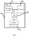
- Fig. 2 is a diagram of a structure of a mobile terminal with a shared RF antenna according to an embodiment of the present invention.
- the mobile terminal comprises a printed circuit board (PCB) 1.
- the PCB comprises a distance sensing module 11, an RF module 12, a filter module 13, and an RF antenna module 14.
- the distance sensing module 11 is electrically connected to the RF antenna module 14 through the filter module 13.
- the RF antenna module 14 is electrically connected to the RF module 12.
- the RF antenna module 14 could generate a low-frequency resonant frequency (determined by the working frequency of the distance sensing module) and a high-frequency resonant frequency (corresponding to the working frequency of the RF module 12) such that the RF antenna module 14 could satisfy the demands of a low-frequency working signal required by the distance sensing module 11 and a high-frequency working signal required by the high-frequency RF module 12.
- the filter module 13 is used to block the unwanted portion of the input signal of the distance sensing module 11. While the mobile terminal is working in a communication mode, the RF antenna module 14 generates a working signal. The working signal is transmitted to the RF module 12 and the filter module 13. The RF module 12 receives the working signal and works accordingly.
- the filter module 13 receives the working signal and filters out the high-frequency portion of the working signal. For example, the filter module 13 could filter out the portion having frequency larger than 600MHz and only allow the signal having the frequency lower than 500 MHz to pass through. The filtered working signal is then transmitted to the distance sensing module 11 as its input signal such that the distance sensing module 11 works accordingly. In this way, it could prevent the distance sensing module 11 from being incorrectly triggered. It could also ensure that the distance sensing module 11 could correctly be triggered when the distance sensing operation is required.
- the distance sensing module 11 is used to perform the distance sensing operation.
- the RF module 12 is used to perform a RF transceiving operation.
- the mobile terminal could be a LTE, 3G or 2G wireless communication smart terminals having the distance sensing function, such as a tablet, a cell phone, a data card, etc. These belong to the scope of the present invention.
- the RF antenna module 14 and the filter module 13 capable of generating high-frequency and low-frequency resonant frequencies are adopted. This reduces the interferences between the distance sensing module 11 and the RF module 12 when they share the same antenna. Because only one shared antenna is used, the number of antennas is reduced and thus the cost is reduced. Furthermore, the above-mentioned issue of interferences is also solved.
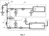
- the filter module comprises the first resistor R1, the first capacitor C1 and the first inductor L1.
- One end of the first resistor R1 is electrically connected to the RF antenna module 14 and the other end of the first resistor R1 is electrically connected to the ground through the first capacitor C1 and is also electrically connected to the distance sensing module 11 through the first inductor L1.
- the first resistor R1 connects the distance sensing module 11 to the RF antenna module 14 to realize the share of antenna.
- the first inductor L1 is used to block high-frequency portions and allow the low-frequency portion (such as signals having a frequency lower than 500 MHz) to pass through.
- the first capacitor C1 is a filter capacitor for filtering out signals having a frequency higher than 600 MHz.
- the filter module 13 When the mobile terminal is working in the communication mode, the communication signal is released to the ground and the signal having the frequency higher than 600 MHz is blocked. This prevents the distance sensing module from being incorrectly triggered.
- the filter module 13 could allow the low-frequency signal to pass through the filter module to trigger the distance sensing module 11 to work. In this way, there is no need to add another distance sensing antenna. Therefore, the cost is reduced and the interference between two antennas is avoided.
- the inductance of the first inductor L1 is 39nh-100nh. This inductance is not too low to affect the RF signal and is not too high to affect the distance sensing function. Thus, this inductance range could ensure the function of the filter module 1.
- the RF antenna module 14 comprises an RF antenna ANT and the second resistor R2.
- the end of the RF antenna ANT is electrically connected to the ground through the second resistor R2 and is electrically connected to one end of the first resistor R1.
- the second resistor R2 is used for protection.
- the RF antenna module 14 could generate the resonant frequency for the distance sensing module 11 to work and could also generate the resonant frequency for the RF module 12 to work. In other words, the RF antenna module 14 could satisfy the requirement of the distance sensing signal of the distance sensing module 11 and the requirement of the RF signal of the RF module 12.
- the end of the RF antenna ANT has an antenna feeding point, which is electrically connected to the RF module 14 and the filter module 13 to ensure the communication signal to pass.
- the RF module 12 comprises the RF chip U1, the third resistor R3, the fourth resistor R4 and the second capacitor C2.
- One end of the third resistor R3 is electrically connected to the end of the RF antenna ANT.
- the other end of the third resistor R3 is electrically connected to the ground through the second capacitor C2 and is also electrically connected to the signal pin of the RF chip U1 through the fourth resistor R4.
- the GND pin of the RF chip U1 is electrically connected to the ground.
- the third resistor R3 and the second capacitor C2 form the RC oscillator circuit for the filter function.
- the fourth resistor R4 is a protection resistor.
- the RF chip could be the RF chip of the model type RF1662. This model type has advantages of stable performance and great function. In another embodiment, the present invention could adopt another model type of the RF chip. This change also falls within the scope of the present invention.
- the RF antenna module 14 When the mobile terminal is working in the communication mode, the RF antenna module 14 generates the communication signal.
- the RC oscillator circuit performs the filter operation on the communication signal and then transfers the filtered signal to the RF chip U1 to drive the RF chip U1 to work such that various RF functions are realized.
- the distance sensing module 11 comprises the distance sensing chip U2, the fifth resistor R5, the sixth resistor R6, and the third capacitor C3.
- One end of the fifth resistor R5 is electrically connected to the other end of the first resistor R1 through the first inductor L1.
- the other end of the fifth resistor R5 is electrically connected to the ground through the third capacitor C3 and is electrically connected to an RX pin of the distance sensing chip U2 through the sixth resistor R6.
- the GND pin of the distance sensing chip U2 is electrically connected to the ground and the VDD pin of the distance sensing chip U2 is electrically connected to a 3.3V voltage source.
- the fifth resistor R5 and the third capacitor C3 form an RC oscillator circuit to perform the filter function.
- the sixth resistor R6 is the protection resistor.
- the distance sensing chip U2 could be the distance sensing chip of the model type LDJ18829M24AC002. This model type has advantages of stable performance and great function. In another embodiment, the present invention could adopt another model type of the distance sensing chip. This change also falls within the scope of the present invention.
- the communication signal is released to the ground through the filter module 13 and the signals having the frequency higher than 600 MHz to prevent the distance sensing function from being incorrectly triggered.
- the filter module 13 could allow the low-frequency signal to pass through the filter module 13.
- the RC oscillator circuit performs the filter operation on the communication signal and transfers the filtered signal to the distance sensing chip U2 to drive the distance sensing chip U2 to work such that the distance sensing function is triggered.
- the first resistor R1 is installed near the antenna feeding point.
- the first inductor L1 is installed near the distance sensing chip U2. This could ensure the filter module 13 to correctly work and prevent the interference between the devices. In this way, the distance sensing function and the RF function could be satisfied by sharing only one antenna.
- the layout wire is shorter on the PCB such that the influence on the RF and low frequency band is avoided.
- the RF antenna module 14 generates the working signal when the mobile terminal is working in the communication mode.
- the working signal is respectively transmitted to the RF module 12 and the filter module 13.
- the RF module 12 receives the working signal and works accordingly.
- the filter module 13 receives the working signal and filters out a high frequency portion from the working signal (e.g. filter out the signal portion having the frequency higher than 600 MHz and allow the signal portion having the frequency lower than 500 MHz to pass). This prevents the distance sensing module from being incorrectly triggered.
- the low frequency signal that passes through the filter module 13 could drive the distance sensing chip U2 to work such that the distance sensing function is triggered.
- the mobile terminal with a shared radio frequency (RF) antenna includes a printed circuit board (PCB).
- a distance sensing module, a radio frequency (RF) module, and a filter module are disposed on the PCB.
- the distance sensing module is configured to perform a distance sensing operation.
- the RF module is configured to perform an RF transceiving operation.
- the mobile terminal of an embodiment adopts the RF antenna module and the filter module respectively capable of generating high-frequency and low-frequency resonant frequencies. Therefore, when the distance sensing module and the RF module shares the same antenna, they do not influence each other. This reduces the number of antenna and solves the issues of the above-mentioned issues of high interferences due to the short distance between two antennas and the metallic material of the two antennas. Furthermore, it also reduces the cost.
Landscapes
- Engineering & Computer Science (AREA)
- Computer Networks & Wireless Communication (AREA)
- Signal Processing (AREA)
- Transceivers (AREA)
- Support Of Aerials (AREA)
- Details Of Aerials (AREA)
- Telephone Function (AREA)
Applications Claiming Priority (2)
| Application Number | Priority Date | Filing Date | Title |
|---|---|---|---|
| CN201710741183.6A CN107547101B (zh) | 2017-08-25 | 2017-08-25 | 一种共用射频天线的移动终端 |
| PCT/CN2018/102348 WO2019037786A1 (fr) | 2017-08-25 | 2018-08-24 | Terminal mobile ayant une antenne radiofréquence partagée |
Publications (3)
| Publication Number | Publication Date |
|---|---|
| EP3675372A1 true EP3675372A1 (fr) | 2020-07-01 |
| EP3675372A4 EP3675372A4 (fr) | 2021-05-26 |
| EP3675372B1 EP3675372B1 (fr) | 2025-05-14 |
Family
ID=60958828
Family Applications (1)
| Application Number | Title | Priority Date | Filing Date |
|---|---|---|---|
| EP18848434.9A Active EP3675372B1 (fr) | 2017-08-25 | 2018-08-24 | Terminal mobile ayant une antenne radiofréquence partagée |
Country Status (4)
| Country | Link |
|---|---|
| US (1) | US20210167809A1 (fr) |
| EP (1) | EP3675372B1 (fr) |
| CN (1) | CN107547101B (fr) |
| WO (1) | WO2019037786A1 (fr) |
Families Citing this family (5)
| Publication number | Priority date | Publication date | Assignee | Title |
|---|---|---|---|---|
| CN107547101B (zh) * | 2017-08-25 | 2020-09-22 | 惠州Tcl移动通信有限公司 | 一种共用射频天线的移动终端 |
| CN113054403B (zh) * | 2019-12-26 | 2022-06-10 | 华为技术有限公司 | 电子设备 |
| CN114339509B (zh) * | 2020-09-30 | 2024-12-17 | 南京矽力微电子(香港)有限公司 | 无线耳机 |
| CN114520942B (zh) * | 2020-11-20 | 2025-03-11 | 南京矽力微电子(香港)有限公司 | 无线耳机 |
| EP4358419A4 (fr) | 2021-09-24 | 2024-10-23 | Samsung Electronics Co., Ltd. | Dispositif électronique comprenant une antenne pour prendre en charge de multiples communications |
Family Cites Families (10)
| Publication number | Priority date | Publication date | Assignee | Title |
|---|---|---|---|---|
| TWI489358B (zh) * | 2010-12-28 | 2015-06-21 | Chi Mei Comm Systems Inc | 具有接近感測器模組之無線通訊裝置 |
| US9578159B2 (en) * | 2011-06-20 | 2017-02-21 | Prasad Muthukumar | Fisheye lens based proactive user interface for mobile devices |
| CN103138794B (zh) * | 2011-11-28 | 2015-02-11 | 启碁科技股份有限公司 | 射频装置及无线通信装置 |
| JP2014082735A (ja) * | 2012-09-26 | 2014-05-08 | Panasonic Corp | 通信機器及び電子機器 |
| US9407335B2 (en) * | 2013-08-06 | 2016-08-02 | Google Technology Holdings LLC | Method and wireless communication device for using an antenna as a sensor device in guiding selection of optimized tuning networks |
| US9621230B2 (en) * | 2014-03-03 | 2017-04-11 | Apple Inc. | Electronic device with near-field antennas |
| US9444425B2 (en) * | 2014-06-20 | 2016-09-13 | Apple Inc. | Electronic device with adjustable wireless circuitry |
| CN104362425B (zh) * | 2014-11-20 | 2018-04-06 | 惠州Tcl移动通信有限公司 | 一种共用nfc天线的移动终端 |
| CN106411420A (zh) * | 2016-09-06 | 2017-02-15 | 惠州Tcl移动通信有限公司 | 一种消除信号干扰的电路及移动设备 |
| CN107547101B (zh) * | 2017-08-25 | 2020-09-22 | 惠州Tcl移动通信有限公司 | 一种共用射频天线的移动终端 |
-
2017
- 2017-08-25 CN CN201710741183.6A patent/CN107547101B/zh active Active
-
2018
- 2018-08-24 EP EP18848434.9A patent/EP3675372B1/fr active Active
- 2018-08-24 US US16/641,656 patent/US20210167809A1/en not_active Abandoned
- 2018-08-24 WO PCT/CN2018/102348 patent/WO2019037786A1/fr not_active Ceased
Also Published As
| Publication number | Publication date |
|---|---|
| US20210167809A1 (en) | 2021-06-03 |
| WO2019037786A1 (fr) | 2019-02-28 |
| EP3675372A4 (fr) | 2021-05-26 |
| EP3675372B1 (fr) | 2025-05-14 |
| CN107547101A (zh) | 2018-01-05 |
| CN107547101B (zh) | 2020-09-22 |
Similar Documents
| Publication | Publication Date | Title |
|---|---|---|
| EP3675372B1 (fr) | Terminal mobile ayant une antenne radiofréquence partagée | |
| JP6015830B2 (ja) | アンテナ装置および電子機器 | |
| US6924773B1 (en) | Integrated dual band H-field shielded loop antenna and E-field antenna | |
| US11881616B2 (en) | Smart ring | |
| US20200076393A1 (en) | Coupled Resonator On-Die Filters for WiFi Applications | |
| US20140269217A1 (en) | User control interface button flex antenna system | |
| CN106252881B (zh) | 天线装置及移动终端 | |
| US10686248B2 (en) | Wireless communication device | |
| CN110708080B (zh) | 通信装置 | |
| KR101492992B1 (ko) | 무선 통신기기 및 안테나 장치 | |
| CN107871993B (zh) | 通信装置的接口模块 | |
| US20200014108A1 (en) | Antenna device | |
| US20100130273A1 (en) | Portable wireless device | |
| TWI599098B (zh) | 行動裝置 | |
| CN103999288B (zh) | 通信终端装置 | |
| US8779982B2 (en) | System for reducing antenna gain deterioration | |
| CN106329113A (zh) | 移动装置 | |
| TWI844029B (zh) | 天線切換電路組及電子裝置 | |
| CN205992592U (zh) | 天线装置及移动终端 | |
| CN119627402A (zh) | 混合天线结构 |
Legal Events
| Date | Code | Title | Description |
|---|---|---|---|
| STAA | Information on the status of an ep patent application or granted ep patent |
Free format text: STATUS: THE INTERNATIONAL PUBLICATION HAS BEEN MADE |
|
| PUAI | Public reference made under article 153(3) epc to a published international application that has entered the european phase |
Free format text: ORIGINAL CODE: 0009012 |
|
| STAA | Information on the status of an ep patent application or granted ep patent |
Free format text: STATUS: REQUEST FOR EXAMINATION WAS MADE |
|
| 17P | Request for examination filed |
Effective date: 20200226 |
|
| AK | Designated contracting states |
Kind code of ref document: A1 Designated state(s): AL AT BE BG CH CY CZ DE DK EE ES FI FR GB GR HR HU IE IS IT LI LT LU LV MC MK MT NL NO PL PT RO RS SE SI SK SM TR |
|
| AX | Request for extension of the european patent |
Extension state: BA ME |
|
| DAV | Request for validation of the european patent (deleted) | ||
| DAX | Request for extension of the european patent (deleted) | ||
| REG | Reference to a national code |
Ref country code: DE Ref legal event code: R079 Free format text: PREVIOUS MAIN CLASS: H04B0001400000 Ipc: H04B0001000000 Ref document number: 602018081990 Country of ref document: DE |
|
| A4 | Supplementary search report drawn up and despatched |
Effective date: 20210422 |
|
| RIC1 | Information provided on ipc code assigned before grant |
Ipc: H04B 1/00 20060101AFI20210416BHEP Ipc: H04B 1/3827 20150101ALI20210416BHEP Ipc: H01Q 1/24 20060101ALI20210416BHEP Ipc: H04B 1/18 20060101ALN20210416BHEP Ipc: H04B 1/04 20060101ALN20210416BHEP |
|
| STAA | Information on the status of an ep patent application or granted ep patent |
Free format text: STATUS: EXAMINATION IS IN PROGRESS |
|
| 17Q | First examination report despatched |
Effective date: 20230307 |
|
| GRAP | Despatch of communication of intention to grant a patent |
Free format text: ORIGINAL CODE: EPIDOSNIGR1 |
|
| STAA | Information on the status of an ep patent application or granted ep patent |
Free format text: STATUS: GRANT OF PATENT IS INTENDED |
|
| RIC1 | Information provided on ipc code assigned before grant |
Ipc: H04B 1/04 20060101ALN20241119BHEP Ipc: H04B 1/18 20060101ALN20241119BHEP Ipc: H01Q 5/50 20150101ALI20241119BHEP Ipc: H01Q 1/24 20060101ALI20241119BHEP Ipc: H04B 1/3827 20150101ALI20241119BHEP Ipc: H04B 1/00 20060101AFI20241119BHEP |
|
| INTG | Intention to grant announced |
Effective date: 20241209 |
|
| P01 | Opt-out of the competence of the unified patent court (upc) registered |
Free format text: CASE NUMBER: APP_9311/2025 Effective date: 20250225 |
|
| GRAS | Grant fee paid |
Free format text: ORIGINAL CODE: EPIDOSNIGR3 |
|
| GRAA | (expected) grant |
Free format text: ORIGINAL CODE: 0009210 |
|
| STAA | Information on the status of an ep patent application or granted ep patent |
Free format text: STATUS: THE PATENT HAS BEEN GRANTED |
|
| AK | Designated contracting states |
Kind code of ref document: B1 Designated state(s): AL AT BE BG CH CY CZ DE DK EE ES FI FR GB GR HR HU IE IS IT LI LT LU LV MC MK MT NL NO PL PT RO RS SE SI SK SM TR |
|
| REG | Reference to a national code |
Ref country code: GB Ref legal event code: FG4D |
|
| REG | Reference to a national code |
Ref country code: CH Ref legal event code: EP |
|
| REG | Reference to a national code |
Ref country code: DE Ref legal event code: R096 Ref document number: 602018081990 Country of ref document: DE |
|
| REG | Reference to a national code |
Ref country code: IE Ref legal event code: FG4D |
|
| REG | Reference to a national code |
Ref country code: NL Ref legal event code: MP Effective date: 20250514 |
|
| PG25 | Lapsed in a contracting state [announced via postgrant information from national office to epo] |
Ref country code: PT Free format text: LAPSE BECAUSE OF FAILURE TO SUBMIT A TRANSLATION OF THE DESCRIPTION OR TO PAY THE FEE WITHIN THE PRESCRIBED TIME-LIMIT Effective date: 20250915 Ref country code: FI Free format text: LAPSE BECAUSE OF FAILURE TO SUBMIT A TRANSLATION OF THE DESCRIPTION OR TO PAY THE FEE WITHIN THE PRESCRIBED TIME-LIMIT Effective date: 20250514 Ref country code: ES Free format text: LAPSE BECAUSE OF FAILURE TO SUBMIT A TRANSLATION OF THE DESCRIPTION OR TO PAY THE FEE WITHIN THE PRESCRIBED TIME-LIMIT Effective date: 20250514 |
|
| PGFP | Annual fee paid to national office [announced via postgrant information from national office to epo] |
Ref country code: DE Payment date: 20250820 Year of fee payment: 8 |
|
| REG | Reference to a national code |
Ref country code: LT Ref legal event code: MG9D |
|
| PG25 | Lapsed in a contracting state [announced via postgrant information from national office to epo] |
Ref country code: NO Free format text: LAPSE BECAUSE OF FAILURE TO SUBMIT A TRANSLATION OF THE DESCRIPTION OR TO PAY THE FEE WITHIN THE PRESCRIBED TIME-LIMIT Effective date: 20250814 Ref country code: GR Free format text: LAPSE BECAUSE OF FAILURE TO SUBMIT A TRANSLATION OF THE DESCRIPTION OR TO PAY THE FEE WITHIN THE PRESCRIBED TIME-LIMIT Effective date: 20250815 |
|
| PG25 | Lapsed in a contracting state [announced via postgrant information from national office to epo] |
Ref country code: NL Free format text: LAPSE BECAUSE OF FAILURE TO SUBMIT A TRANSLATION OF THE DESCRIPTION OR TO PAY THE FEE WITHIN THE PRESCRIBED TIME-LIMIT Effective date: 20250514 Ref country code: PL Free format text: LAPSE BECAUSE OF FAILURE TO SUBMIT A TRANSLATION OF THE DESCRIPTION OR TO PAY THE FEE WITHIN THE PRESCRIBED TIME-LIMIT Effective date: 20250514 |
|
| REG | Reference to a national code |
Ref country code: AT Ref legal event code: MK05 Ref document number: 1795698 Country of ref document: AT Kind code of ref document: T Effective date: 20250514 |
|
| PG25 | Lapsed in a contracting state [announced via postgrant information from national office to epo] |
Ref country code: BG Free format text: LAPSE BECAUSE OF FAILURE TO SUBMIT A TRANSLATION OF THE DESCRIPTION OR TO PAY THE FEE WITHIN THE PRESCRIBED TIME-LIMIT Effective date: 20250514 |
|
| PGFP | Annual fee paid to national office [announced via postgrant information from national office to epo] |
Ref country code: GB Payment date: 20250820 Year of fee payment: 8 |
|
| PG25 | Lapsed in a contracting state [announced via postgrant information from national office to epo] |
Ref country code: HR Free format text: LAPSE BECAUSE OF FAILURE TO SUBMIT A TRANSLATION OF THE DESCRIPTION OR TO PAY THE FEE WITHIN THE PRESCRIBED TIME-LIMIT Effective date: 20250514 |
|
| PG25 | Lapsed in a contracting state [announced via postgrant information from national office to epo] |
Ref country code: AT Free format text: LAPSE BECAUSE OF FAILURE TO SUBMIT A TRANSLATION OF THE DESCRIPTION OR TO PAY THE FEE WITHIN THE PRESCRIBED TIME-LIMIT Effective date: 20250514 |
|
| PGFP | Annual fee paid to national office [announced via postgrant information from national office to epo] |
Ref country code: FR Payment date: 20250828 Year of fee payment: 8 |
|
| PG25 | Lapsed in a contracting state [announced via postgrant information from national office to epo] |
Ref country code: RS Free format text: LAPSE BECAUSE OF FAILURE TO SUBMIT A TRANSLATION OF THE DESCRIPTION OR TO PAY THE FEE WITHIN THE PRESCRIBED TIME-LIMIT Effective date: 20250814 |
|
| PG25 | Lapsed in a contracting state [announced via postgrant information from national office to epo] |
Ref country code: IS Free format text: LAPSE BECAUSE OF FAILURE TO SUBMIT A TRANSLATION OF THE DESCRIPTION OR TO PAY THE FEE WITHIN THE PRESCRIBED TIME-LIMIT Effective date: 20250914 |
|
| PG25 | Lapsed in a contracting state [announced via postgrant information from national office to epo] |
Ref country code: LV Free format text: LAPSE BECAUSE OF FAILURE TO SUBMIT A TRANSLATION OF THE DESCRIPTION OR TO PAY THE FEE WITHIN THE PRESCRIBED TIME-LIMIT Effective date: 20250514 |
|
| PG25 | Lapsed in a contracting state [announced via postgrant information from national office to epo] |
Ref country code: SM Free format text: LAPSE BECAUSE OF FAILURE TO SUBMIT A TRANSLATION OF THE DESCRIPTION OR TO PAY THE FEE WITHIN THE PRESCRIBED TIME-LIMIT Effective date: 20250514 Ref country code: DK Free format text: LAPSE BECAUSE OF FAILURE TO SUBMIT A TRANSLATION OF THE DESCRIPTION OR TO PAY THE FEE WITHIN THE PRESCRIBED TIME-LIMIT Effective date: 20250514 |
|
| PG25 | Lapsed in a contracting state [announced via postgrant information from national office to epo] |
Ref country code: CZ Free format text: LAPSE BECAUSE OF FAILURE TO SUBMIT A TRANSLATION OF THE DESCRIPTION OR TO PAY THE FEE WITHIN THE PRESCRIBED TIME-LIMIT Effective date: 20250514 |
|
| PG25 | Lapsed in a contracting state [announced via postgrant information from national office to epo] |
Ref country code: EE Free format text: LAPSE BECAUSE OF FAILURE TO SUBMIT A TRANSLATION OF THE DESCRIPTION OR TO PAY THE FEE WITHIN THE PRESCRIBED TIME-LIMIT Effective date: 20250514 |
|
| PG25 | Lapsed in a contracting state [announced via postgrant information from national office to epo] |
Ref country code: RO Free format text: LAPSE BECAUSE OF FAILURE TO SUBMIT A TRANSLATION OF THE DESCRIPTION OR TO PAY THE FEE WITHIN THE PRESCRIBED TIME-LIMIT Effective date: 20250514 Ref country code: SK Free format text: LAPSE BECAUSE OF FAILURE TO SUBMIT A TRANSLATION OF THE DESCRIPTION OR TO PAY THE FEE WITHIN THE PRESCRIBED TIME-LIMIT Effective date: 20250514 |
|
| PG25 | Lapsed in a contracting state [announced via postgrant information from national office to epo] |
Ref country code: IT Free format text: LAPSE BECAUSE OF FAILURE TO SUBMIT A TRANSLATION OF THE DESCRIPTION OR TO PAY THE FEE WITHIN THE PRESCRIBED TIME-LIMIT Effective date: 20250514 |
|
| REG | Reference to a national code |
Ref country code: DE Ref legal event code: R097 Ref document number: 602018081990 Country of ref document: DE |
|
| PLBE | No opposition filed within time limit |
Free format text: ORIGINAL CODE: 0009261 |
|
| STAA | Information on the status of an ep patent application or granted ep patent |
Free format text: STATUS: NO OPPOSITION FILED WITHIN TIME LIMIT |
|
| REG | Reference to a national code |
Ref country code: CH Ref legal event code: H13 Free format text: ST27 STATUS EVENT CODE: U-0-0-H10-H13 (AS PROVIDED BY THE NATIONAL OFFICE) Effective date: 20260324 |
|
| REG | Reference to a national code |
Ref country code: CH Ref legal event code: L10 Free format text: ST27 STATUS EVENT CODE: U-0-0-L10-L00 (AS PROVIDED BY THE NATIONAL OFFICE) Effective date: 20260325 |
|
| PG25 | Lapsed in a contracting state [announced via postgrant information from national office to epo] |
Ref country code: MC Free format text: LAPSE BECAUSE OF FAILURE TO SUBMIT A TRANSLATION OF THE DESCRIPTION OR TO PAY THE FEE WITHIN THE PRESCRIBED TIME-LIMIT Effective date: 20250514 |
|
| PG25 | Lapsed in a contracting state [announced via postgrant information from national office to epo] |
Ref country code: LU Free format text: LAPSE BECAUSE OF NON-PAYMENT OF DUE FEES Effective date: 20250824 |
|
| 26N | No opposition filed |
Effective date: 20260217 |
|
| PG25 | Lapsed in a contracting state [announced via postgrant information from national office to epo] |
Ref country code: CH Free format text: LAPSE BECAUSE OF NON-PAYMENT OF DUE FEES Effective date: 20250831 |