EP3675573B1 - Signalübertragungsverfahren, zugehörige vorrichtung und system - Google Patents
Signalübertragungsverfahren, zugehörige vorrichtung und system Download PDFInfo
- Publication number
- EP3675573B1 EP3675573B1 EP17924437.1A EP17924437A EP3675573B1 EP 3675573 B1 EP3675573 B1 EP 3675573B1 EP 17924437 A EP17924437 A EP 17924437A EP 3675573 B1 EP3675573 B1 EP 3675573B1
- Authority
- EP
- European Patent Office
- Prior art keywords
- configuration
- bit
- configurations
- state
- bit sequence
- Prior art date
- Legal status (The legal status is an assumption and is not a legal conclusion. Google has not performed a legal analysis and makes no representation as to the accuracy of the status listed.)
- Active
Links
Images




Classifications
-
- H—ELECTRICITY
- H04—ELECTRIC COMMUNICATION TECHNIQUE
- H04W—WIRELESS COMMUNICATION NETWORKS
- H04W72/00—Local resource management
- H04W72/12—Wireless traffic scheduling
- H04W72/1263—Mapping of traffic onto schedule, e.g. scheduled allocation or multiplexing of flows
- H04W72/1268—Mapping of traffic onto schedule, e.g. scheduled allocation or multiplexing of flows of uplink data flows
-
- H—ELECTRICITY
- H04—ELECTRIC COMMUNICATION TECHNIQUE
- H04L—TRANSMISSION OF DIGITAL INFORMATION, e.g. TELEGRAPHIC COMMUNICATION
- H04L5/00—Arrangements affording multiple use of the transmission path
- H04L5/003—Arrangements for allocating sub-channels of the transmission path
- H04L5/0053—Allocation of signalling, i.e. of overhead other than pilot signals
-
- H—ELECTRICITY
- H04—ELECTRIC COMMUNICATION TECHNIQUE
- H04L—TRANSMISSION OF DIGITAL INFORMATION, e.g. TELEGRAPHIC COMMUNICATION
- H04L1/00—Arrangements for detecting or preventing errors in the information received
- H04L1/0001—Systems modifying transmission characteristics according to link quality, e.g. power backoff
- H04L1/0023—Systems modifying transmission characteristics according to link quality, e.g. power backoff characterised by the signalling
- H04L1/0026—Transmission of channel quality indication
-
- H—ELECTRICITY
- H04—ELECTRIC COMMUNICATION TECHNIQUE
- H04L—TRANSMISSION OF DIGITAL INFORMATION, e.g. TELEGRAPHIC COMMUNICATION
- H04L1/00—Arrangements for detecting or preventing errors in the information received
- H04L1/12—Arrangements for detecting or preventing errors in the information received by using return channel
- H04L1/16—Arrangements for detecting or preventing errors in the information received by using return channel in which the return channel carries supervisory signals, e.g. repetition request signals
- H04L1/1607—Details of the supervisory signal
- H04L1/1671—Details of the supervisory signal the supervisory signal being transmitted together with control information
-
- H—ELECTRICITY
- H04—ELECTRIC COMMUNICATION TECHNIQUE
- H04L—TRANSMISSION OF DIGITAL INFORMATION, e.g. TELEGRAPHIC COMMUNICATION
- H04L1/00—Arrangements for detecting or preventing errors in the information received
- H04L1/12—Arrangements for detecting or preventing errors in the information received by using return channel
- H04L1/16—Arrangements for detecting or preventing errors in the information received by using return channel in which the return channel carries supervisory signals, e.g. repetition request signals
- H04L1/18—Automatic repetition systems, e.g. Van Duuren systems
- H04L1/1806—Go-back-N protocols
-
- H—ELECTRICITY
- H04—ELECTRIC COMMUNICATION TECHNIQUE
- H04L—TRANSMISSION OF DIGITAL INFORMATION, e.g. TELEGRAPHIC COMMUNICATION
- H04L1/00—Arrangements for detecting or preventing errors in the information received
- H04L1/12—Arrangements for detecting or preventing errors in the information received by using return channel
- H04L1/16—Arrangements for detecting or preventing errors in the information received by using return channel in which the return channel carries supervisory signals, e.g. repetition request signals
- H04L1/18—Automatic repetition systems, e.g. Van Duuren systems
- H04L1/1812—Hybrid protocols; Hybrid automatic repeat request [HARQ]
-
- H—ELECTRICITY
- H04—ELECTRIC COMMUNICATION TECHNIQUE
- H04L—TRANSMISSION OF DIGITAL INFORMATION, e.g. TELEGRAPHIC COMMUNICATION
- H04L1/00—Arrangements for detecting or preventing errors in the information received
- H04L1/12—Arrangements for detecting or preventing errors in the information received by using return channel
- H04L1/16—Arrangements for detecting or preventing errors in the information received by using return channel in which the return channel carries supervisory signals, e.g. repetition request signals
- H04L1/18—Automatic repetition systems, e.g. Van Duuren systems
- H04L1/1812—Hybrid protocols; Hybrid automatic repeat request [HARQ]
- H04L1/1819—Hybrid protocols; Hybrid automatic repeat request [HARQ] with retransmission of additional or different redundancy
-
- H—ELECTRICITY
- H04—ELECTRIC COMMUNICATION TECHNIQUE
- H04L—TRANSMISSION OF DIGITAL INFORMATION, e.g. TELEGRAPHIC COMMUNICATION
- H04L5/00—Arrangements affording multiple use of the transmission path
- H04L5/003—Arrangements for allocating sub-channels of the transmission path
- H04L5/0044—Allocation of payload; Allocation of data channels, e.g. PDSCH or PUSCH
- H04L5/0046—Determination of the number of bits transmitted on different sub-channels
-
- H—ELECTRICITY
- H04—ELECTRIC COMMUNICATION TECHNIQUE
- H04W—WIRELESS COMMUNICATION NETWORKS
- H04W72/00—Local resource management
- H04W72/04—Wireless resource allocation
- H04W72/044—Wireless resource allocation based on the type of the allocated resource
- H04W72/0446—Resources in time domain, e.g. slots or frames
-
- H—ELECTRICITY
- H04—ELECTRIC COMMUNICATION TECHNIQUE
- H04W—WIRELESS COMMUNICATION NETWORKS
- H04W72/00—Local resource management
- H04W72/20—Control channels or signalling for resource management
- H04W72/21—Control channels or signalling for resource management in the uplink direction of a wireless link, i.e. towards the network
-
- H—ELECTRICITY
- H04—ELECTRIC COMMUNICATION TECHNIQUE
- H04L—TRANSMISSION OF DIGITAL INFORMATION, e.g. TELEGRAPHIC COMMUNICATION
- H04L1/00—Arrangements for detecting or preventing errors in the information received
- H04L1/12—Arrangements for detecting or preventing errors in the information received by using return channel
- H04L1/16—Arrangements for detecting or preventing errors in the information received by using return channel in which the return channel carries supervisory signals, e.g. repetition request signals
- H04L1/18—Automatic repetition systems, e.g. Van Duuren systems
- H04L1/1829—Arrangements specially adapted for the receiver end
- H04L1/1861—Physical mapping arrangements
Definitions
- This application relates to the field of wireless communications technologies, and in particular, to a signal transmission method, a related apparatus, and a system.
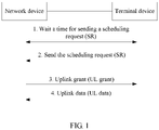
- a process from a time when a terminal device has no to-be-scheduled resource to a time when the terminal device sends an uplink channel may include: UE waits a time for sending a scheduling request (scheduling request, SR), and sends the SR; an eNB receives the SR and generates a scheduling grant, and sends the scheduling grant; the UE receives the scheduling grant and sends an uplink channel; and if a data volume of the UE is not completely sent, the UE further needs to wait for a next scheduling grant.
- SR scheduling request
- hybrid automatic repeat request Hybrid Automatic Repeat reQuest, HARQ
- HARQ Hybrid Automatic Repeat reQuest
- the negative scheduling request indicates that there is currently no uplink data for the terminal, or there is currently no need to allocate a resource used for transmission to the terminal.
- a fifth-generation mobile radio technology (NR) system there are a plurality of service types, and the plurality of service types correspond to different service requirements.
- uRLLC requires a short latency and high reliability, to be specific, successful transmission within 1 ms
- eMBB requires high spectral efficiency but has no latency requirement
- mMTC requires periodic sending at low power.
- the terminal device needs to request for resources of different attributes (Numerology/TTI), to satisfy service requirements of the different services.
- the one scheduling request bit in LTE-A does not support a multi-service scenario in future 5G, and this problem needs to be urgently resolved currently.
- 3GPP document R1-1714072 discloses a method for how to convey scheduling request when SR occurs in the same symbol/slot with other UCI.
- the UE can be configured in NR with multiple SR configurations/processes associated with different logical channels or services such as eMBB and URLLC. Sequence selection is used to indicate SR+HARQ-ACK.
- the present invention is defined by the methods of independent claims 1 or 2, by the apparatus of independent claims 7 or 8, by the computer readable storage medium of independent claim 9, and by the communication system of independent claim 10. Additional features of the invention are presented in the dependent claims. In the following, parts of the description and drawings referring to embodiments, which are not covered by the claims are not presented as embodiments of the invention, but as examples useful for understanding the invention.
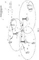
- FIG. 3 shows a wireless communications system in this application.
- the wireless communications system may be a global system for mobile communications (Global System of Mobile communication, GSM) system, a code division multiple access (Code Division Multiple Access, CDMA) system, a wideband code division multiple access (Wideband Code Division Multiple Access Wireless, WCDMA) system, a general packet radio service (General Packet Radio Service, GPRS) system, a universal mobile telecommunications system (Universal Mobile Telecommunications System, UMTS), or a long term evolution (Long Term Evolution, LTE) system; or may be a fifth-generation mobile communications (the 5th Generation, 5G) system, a new radio (NR) system, a machine-to-machine (Machine to Machine, M2M) communications system, or the like.
- the wireless communications system 100 may include: one or more network devices 101, one or more terminal devices 103, and a core network 115.
- the terminal device 103 may also be referred to as user equipment (User Equipment, UE), an access terminal, a subscriber unit, a subscriber station, a mobile station, a remote station, a remote terminal, a mobile device, a user terminal, a terminal, a wireless communications device, a user agent, or a user apparatus.
- UE user equipment
- UE User Equipment
- the terminal device 103 may be a station (STATION, ST) in a wireless local area network (Wireless Local Area Network, WLAN), a cellular phone, a cordless phone, a session initiation protocol (Session Initiation Protocol, SIP) phone, a wireless local loop (Wireless Local Loop, WLL) station, a personal digital assistant (Personal Digital Assistant, PDA) device, a handheld device or a computing device having a wireless communications function, another processing device connected to a wireless modem, a vehicle-mounted device, a wearable device, a terminal device 103 in a next-generation communications system such as a fifth-generation (fifth-generation, 5G) communications network, a terminal device 103 in a public land mobile network (Public Land Mobile Network, PLMN) network, a terminal device 103 in a new radio (New Radio, NR) communications system, or the like.
- a wireless local area network Wireless Local Area Network, WLAN
- WLAN Wireless Local Area Network
- SIP Session In
- the terminal device 103 may be a wearable device.
- the wearable device may also be referred to as a wearable intelligent device.
- the wearable intelligent device is a collective name of wearable devices, such as glasses, gloves, watches, clothes, and shoes, obtained by performing intelligent design and development on daily wearables by using a wearable technology.
- the wearable device is a portable device that is directly worn on a human body or is integrated into a user's clothes or ornaments.
- the wearable device is not merely a hardware device, but further implements a powerful function through software support, data exchange, and cloud-based interaction.
- the wearable intelligent device includes a device that provides a complete function, has a large size, and can implement all or some functions without relying on a smartphone, for example, a smartwatch or smart glasses; and includes a device that focuses only on a specific type of application and needs to be used in combination with another device such as a smartphone, for example, various smart bands and smart jewelry used for vital sign monitoring.
- the network device 101 may be a device, configured to communicate with a mobile device, in a network.
- the network device 101 may be an access point (Access Point, AP) in a WLAN, a base transceiver station (Base Transceiver Station, BTS) in a GSM or CDMA system, a NodeB (NodeB, NB) in a WCDMA system, an evolved NodeB (Evolutional NodeB, eNB or eNodeB) in an LTE system, a relay station or an access point, a vehicle-mounted device, a wearable device, a network device 101 in a 5G network, a network device 101 in a PLMN network, a new-generation NodeB (new generation NodeB, gNodeB) in an NR system, or the like.
- Access Point Access Point
- BTS Base Transceiver Station
- NodeB NodeB
- eNB evolved NodeB
- eNodeB evolved NodeB
- LTE Long Term Evolutional NodeB
- eNB evolved NodeB
- eNodeB evolved Node
- the network device 101 provides a cell with a service
- the terminal device 103 communicates with the network device 101 by using a transmission resource (for example, a frequency domain resource, or referred to as a frequency spectrum resource) used by the cell.
- the cell may be a cell corresponding to the network device 101 (for example, a base station).
- the cell may belong to a macro base station, or a base station corresponding to a small cell (small cell).
- the small cell herein may include: a metro cell (Metro cell), a micro cell (Micro cell), a pico cell (Pico cell), a femto cell (Femto cell), or the like. These small cells feature a small coverage area and low transmitting power, and are suitable for providing a high-rate data transmission service.
- a plurality of cells may simultaneously work at a same frequency on a carrier, and it may be considered that the concept "carrier” is equivalent to the concept "cell” in some special scenarios.
- a carrier aggregation (Carrier Aggregation, CA) scenario when a secondary carrier is configured for UE, configuration information carries both a carrier index of the secondary carrier and a cell identity (Cell Identity, Cell ID) of a secondary cell working on the secondary carrier.
- Cell Identity, Cell ID Cell Identity
- the concept "carrier” is equivalent to the concept "cell”.
- UE's access to a carrier is equivalent to the UE's access to a cell.
- the network device 101 may work on a licensed frequency band or a license-free frequency band.
- FIG. 4 shows a terminal device 200 according to some embodiments of this application. As shown in FIG.
- the terminal device 200 may include: one or more terminal processors 201, a memory 202, a communications interface 203, a receiver 205, a transmitter 206, a coupler 207, an antenna 208, a user interface 209, and an input/output module (including an audio input/output module 210, a button input module 211, a display 212, and the like). These components may be connected by using a bus 204 or in another manner, and are connected, for example, by using a bus in FIG. 4 .
- the communications interface 203 may be used by the terminal device 200 to communicate with another communications device, for example, a network device.
- the network device may be a network device 300 shown in FIG. 5 .
- the communications interface 203 may be a long term evolution (LTE) (4G) communications interface, or may be a 5G communications interface or a new radio communications interface.
- LTE long term evolution
- the communications interface 203 is not limited to a wireless communications interface.
- the terminal device 200 may be further equipped with a wired communications interface 203, for example, a local access network (Local Access Network, LAN) interface.
- LAN local access network
- the transmitter 206 may be configured to perform transmitting processing, for example, signal modulation, on a signal output by the terminal processor 201.
- the receiver 205 may be configured to perform reception processing, for example, signal demodulation, on a mobile communications signal received by the antenna 208.
- the transmitter 206 and the receiver 205 may be considered as a wireless modem.
- the terminal device 200 there may be one or more transmitters 206 and one or more receivers 205.
- the antenna 208 may be configured to convert electromagnetic energy in a transmission line into an electromagnetic wave in free space, or convert an electromagnetic wave in free space into electromagnetic energy in a transmission line.
- the coupler 207 is configured to split a mobile communications signal received by the antenna 208 into a plurality of signals, and allocate the signals to a plurality of receivers 205.
- the terminal device 200 may further include other communications components, such as a GPS module, a Bluetooth (Bluetooth) module, and a wireless fidelity (Wireless Fidelity, Wi-Fi) module, in addition to the transmitter 206 and the receiver 205 shown in FIG. 4 .
- the terminal device 200 may further support other wireless communications signals, such as a satellite signal and a short-wave signal, in addition to the foregoing described wireless communications signal.
- the terminal device 200 may be further equipped with a wired network interface (for example, a LAN interface) to support wired communication, in addition to wireless communication.
- the input/output module may be configured to implement interaction between the terminal device 200 and a user/an external environment, and may mainly include the audio input/output module 210, the button input module 211, the display 212, and the like. Specifically, the input/output module may further include: a camera, a touchscreen, a sensor, or the like. The input/output module communicates with the terminal process 201 only by using the user interface 209.
- the memory 202 is coupled to the terminal processor 201, and is configured to store various software programs and/or a plurality of sets of instructions.
- the memory 202 may include a high-speed random access memory, and may also include a non- transitory memory, for example, one or more disk storage devices, a flash memory, or another non-transitory solid state storage device.
- the memory 202 may store an operating system (briefly referred to as a system below), for example, an embedded operating system such as Android, IoS, Windows, or Linux.
- the memory 202 may further store a network communications program.
- the network communications program may be used to communicate with one or more additional devices, one or more terminal devices, and one or more network devices.
- the memory 202 may further store a user interface program.
- the user interface program may vividly display content of an application program by using a graphical operation interface; and receive, by using input controls such as a menu, a dialog box, and a button, a control operation performed by a user on the application program
- the memory 202 may be configured to store a program for implementing, on the terminal device 200 side, a signal transmission method provided in one or more embodiments of this application.
- the terminal processor 201 may be configured to read and execute a computer readable instruction.
- the terminal processor 201 may be configured to invoke a program stored in the memory 202, for example, a program for implementing, on the terminal device 200 side, a signal transmission method provided in one or more embodiments of this application, and execute an instruction included in this program.
- the terminal device 200 may be the terminal 103 in the wireless communications system 100 shown in FIG. 3 , and may be implemented as a mobile device, a mobile station (mobile station), a mobile unit (mobile unit), a radio unit, a remote unit, a user agent, a mobile client, or the like.
- the terminal device 200 shown in FIG. 4 is merely an implementation of an embodiment of this application. During practical application, the terminal device 200 may further include more or fewer components, and this is not limited herein.
- FIG. 5 shows a network device 300 according to some embodiments of this application.
- the network device 300 may include: one or more network device processors 301, one or more memories 302, one or more communications interfaces 303, one or more transmitters 305, one or more receivers 306, one or more couplers 307, and one or more antennas 308. These components may be connected by using a bus 304 or connected in another manner.
- FIG. 5 is an example by using a bus.
- the communications interface 303 may be used by the network device 300 to communicate with another communications device, for example, a terminal device or another network device.
- the terminal device may be the terminal device 200 shown in FIG. 4 .
- the communications interface 303 may be a long term evolution (LTE) (4G) communications interface, or may be a 5G communications interface or a new radio communications interface.
- LTE long term evolution
- the communications interface 303 is not limited to a wireless communications interface.
- the network device 300 may be further equipped with a wired communications interface 303 to support wired communication. For example, a backhaul link between one network device 300 and another network device 300 may be a wired communications connection.
- the transmitter 305 may be configured to perform transmit processing, for example, signal modulation, on a signal output by the network device processor 301.
- the receiver 306 may be configured to perform reception processing, for example, signal demodulation, on a mobile communications signal received by the antenna 308.
- the transmitter 305 and the receiver 306 may be considered as a wireless modem.
- the antenna 308 may be configured to convert electromagnetic energy in a transmission line into an electromagnetic wave in free space, or convert an electromagnetic wave in free space into electromagnetic energy in a transmission line.
- the coupler 307 may be configured to split a mobile communications signal into a plurality of signals, and allocate the signals to a plurality of receivers 306.
- the memory 302 is coupled to the network device processor 301, and is configured to store various software programs and/or a plurality of sets of instructions.
- the memory 302 may include a high-speed random access memory, and may also include a non-transitory memory, for example, one or more disk storage devices, a flash memory, or another non- transitory solid state storage device.
- the memory 302 may store an operating system (briefly referred to as a system below), for example, an embedded operating system such as uCOS, VxWorks, or RTLinux.
- the memory 302 may further store a network communications program.
- the network communications program may be used to communicate with one or more additional devices, one or more terminal devices, and one or more network devices.
- the network device processor 301 may be configured to perform radio channel management, implement establishment and disconnection of a call or a communication link, and provide a user in a current control area with cell handover control and the like.
- the network device processor 301 may include: an administration module/communication module (Administration Module/Communication Module, AM/CM) (a center configured to perform speech channel switching and information exchange), a basic module (Basic Module, BM) (configured to implement call processing, signaling processing, radio resource management, radio link management, and a circuit maintenance function), a transcoder and submultiplexer (Transcoder and SubMultiplexer, TCSM) unit (configured to implement multiplexing, demultiplexing, and a transcoding function), and the like.
- an administration module/communication module (Administration Module/Communication Module, AM/CM) (a center configured to perform speech channel switching and information exchange), a basic module (Basic Module, BM) (configured to implement call processing, signaling processing, radio resource management, radio link management,
- the network device processor 301 may be configured to read and execute a computer readable instruction. Specifically, the network device processor 301 may be configured to invoke a program stored in the memory 302, for example, a program for implementing, on the network device 300 side, a signal transmission method provided in one or more embodiments of this application, and execute an instruction included in this program.
- the network device 300 may be the base station 101 in the wireless communications system 100 shown in FIG. 3 , and may be implemented as a base transceiver station, a wireless transceiver, a basic service set (BSS), an extended service set (ESS), a NodeB, an eNodeB, an access point or a TRP, or the like.
- BSS basic service set
- ESS extended service set
- NodeB NodeB
- eNodeB an access point or a TRP, or the like.
- the network device 300 shown in FIG. 5 is merely an implementation of an embodiment of this application. During practical application, the network device 300 may further include more or fewer components, and this is not limited herein.
- this application provides a signal transmission method, as described in detail below.
- Scheduling request configuration (scheduling request configuration, briefly referred to as an SR configuration below)
- An SR configuration may be dynamically configured by a network device for a terminal, or may be configured by a network device for a terminal by using higher layer signaling.
- the higher layer signaling may be signaling sent by a higher protocol layer.
- the higher protocol layer is at least one protocol layer in all protocol layers above a physical layer. Specifically, the higher protocol layer may be at least one of the following protocol layers: a medium access control (Medium Access Control, MAC) layer, a radio link control (Radio Link Control, RLC) layer, a packet data convergence protocol (Packet Data Convergence Protocol, PDCP) layer, a radio resource control (Radio Resource Control, RRC) layer, a non-access stratum (Non-Access Stratum, NAS) layer, and the like.
- Medium Access Control Medium Access Control
- RLC Radio Link Control
- PDCP Packet Data Convergence Protocol
- RRC Radio Resource Control
- NAS non-access stratum
- an SR configuration is associated with a first scheduling request(s) in at least one of the following manners: 1.
- the SR configuration may be used to indicate a time-domain location and/or a frequency-domain location of the first scheduling request(s).
- the SR configuration indicates a time period in which the first scheduling request(s) can be sent, in other words, a time-domain location corresponding to the time period is a time-domain location at which the first scheduling request(s) can be sent.
- the SR configuration indicates a subcarrier spacing on which the first scheduling request(s) can be sent, in other words, a subcarrier size corresponding to the subcarrier spacing is a subcarrier on which the first scheduling request(s) can be sent.
- Table 1-1, Table 1-2, and Table 1-3 show examples of three SR configurations.
- Table 1-1 SR configuration index number Time-domain location SR configuration #0 Once every 2 ms SR configuration #1 Once every seven symbols SR configuration #2 Once every slot Table 1-2 SR configuration index number Frequency-domain location SR configuration #0 Physical resource block 1 SR configuration #1 Physical resource block 2 SR configuration #2 Physical resource block 1 Table 1-3 SR configuration index number Time-domain location Frequency-domain location SR configuration #0 Once every 2 ms Physical resource block 1 SR configuration #1 Once every seven symbols Physical resource block 2 SR configuration #2 Once every symbol Physical resource block 3 It can be learned that, a plurality of SR configurations may indicate a same time-domain location, or may indicate different time-domain locations; and a plurality of SR configurations may indicate a same frequency-domain location, or may indicate different frequency-domain locations.
- the SR configuration may be used to indicate a length of a time unit occupied by an uplink control channel that carries the first scheduling request(s) and/or a size of a subcarrier spacing occupied by an uplink control channel that carries the first scheduling request(s).
- the SR configuration indicates that a length of a time unit occupied by an uplink control channel that carries the first scheduling request(s) is two symbols, in other words, the first scheduling request(s) can be sent on a two-symbol uplink control channel.
- Table 2-1, Table 2-2, and Table 2-3 show examples of three SR configurations.
- the SR configuration may be used to indicate an attribute (Numerology/TTI/logical channel) of a resource requested in the first scheduling request(s).
- Different SR configurations are for different services, because a requirement for an attribute of a resource varies according to different services.
- an attribute of a frequency-domain resource requested in the first scheduling request(s) is a first numerology (for example, a first subcarrier spacing (subcarrier spacing, SCS)), and/or an attribute of a time-domain resource requested in the first scheduling request(s) is a first time unit, and/or a logical channel requested in the first scheduling request(s) is a first logical channel, and/or a priority of a logical channel requested in the first scheduling request(s) is a second priority.
- Table 3-1, Table 3-2, Table 3-3, and Table 3-4 show examples of three SR configurations.
- Table 3-1 SR configuration index number Attribute of a requested time-domain resource (time unit) SR configuration #0 1 ms SR configuration #1 2 symbols SR configuration #2 1 slot Table 3-2 SR configuration index number Attribute of a requested time-domain resource (time unit) Service SR configuration #0 1 ms Service #0 SR configuration #1 2 symbols Service #1 SR configuration #2 1 slot Service #2 Table 3-3 SR configuration index number Attribute of a requested time-domain resource (time unit) Attribute (Numerology) of a requested frequency-domain resource SR configuration #0 1 ms 15 kHz SR configuration #1 2 symbols 60 kHz SR configuration #2 1 slot 30 kHz Table 3-4 SR configuration index number Attribute of a requested time-domain resource (time unit) Service SR configuration #0 1 ms Service #0 SR configuration #1 2 symbols Service #1 SR configuration #2 1 slot Service #2
- a plurality of SR configurations may indicate a same attribute of a requested time-domain resource, or may indicate different attributes of a requested time-domain resource; and a plurality of SR configurations may indicate a same attribute of a requested frequency-domain resource, or may indicate different attributes of a requested frequency-domain resource.
- Scheduling request bit (scheduling request bit, briefly referred to as an SR bit(s) below)
- the SR bit(s) is used to indicate an SR(s) reported by a terminal device, and specifically indicate an SR(s) associated with a specific SR configuration(s) and indicate whether the reported SR(s) associated with the SR configuration(s) is a positive SR(s) or a negative SR(s).
- SR bits There may be one or more SR bits.
- a quantity of SR bits is greater than or equal to 2.
- the quantity of SR bits may be related to a quantity of SR configurations.
- an SR bit(s) and a HARQ bit(s) are carried on a same uplink control channel.
- a terminal may determine a quantity of SR bits based on a quantity of SR configurations.
- the quantity of SR bits may be equal to the quantity of SR configurations.
- the quantity of SR bits is equal to: ceil(log 2 (1+N configuration )), where N configuration represents the quantity of SR configurations, and ceil represents rounding up to a next integer.
- an SR configuration #0 and an SR configuration #1 in Table 3-4 are SR configurations in a slot #0.
- the terminal may indicate, by using two bits, SRs associated with the SR configurations in the slot #0 that are configured for the terminal.
- One bit (for example, a most significant bit) is used to indicate whether an SR associated with the SR configuration #0 is a positive SR or a negative SR.
- the other bit (for example, a least significant bit) is used to indicate whether an SR associated with the SR configuration #1 is a positive SR or a negative SR.
- the two bits are SR bits, and one bit corresponds to one SR configuration.
- the terminal may indicate, still by using two bits, SRs associated with the SR configurations in the slot #0 that are configured for the terminal.
- the two bits are "01" it indicates that the terminal device reports, in the slot #0, only a positive SR associated with the SR configuration #1 and does not report an SR associated with the SR configuration #0; or when the two bits are "10", it indicates that the terminal device reports, in the slot #0, only a positive SR associated with the SR configuration #0 and does not report an SR associated with the SR configuration #1; or when the two bits are "00", it indicates that the terminal device reports, in the slot #0, both a negative SR associated with the SR configuration #0 and a negative SR associated with the SR configuration #1.
- a length of one time unit may be set to any value, and is not limited herein.
- one time unit may include one or more subframes.
- one time unit may include one or more slots.
- one time unit may include one or more mini-slots.
- one time unit may include one or more symbols.
- one time unit may include one or more transmission time intervals (Transmission Time Interval, TTI).
- TTI Transmission Time Interval
- one time unit may include one or more short transmission time intervals (short Transmission Time Interval, sTTI).
- short Transmission Time Interval sTTI
- one time unit may correspond to a time mode.
- a first time mode is a two-symbol or three-symbol transmission time interval
- a second time mode is a seven-symbol transmission time interval.
- the mini-slot includes one or more symbols, and is less than or equal to a slot.
- the mini-slot may be a mini-slot in a system with a 60 kHz subcarrier spacing, or may be a mini-slot in a system with a 15 kHz subcarrier spacing, and this is not limited in the embodiments of the present invention.
- the slot includes one or more symbols.
- the slot may be a slot in a system with a 60 kHz subcarrier spacing, or may be a slot in a system with a 15 kHz subcarrier spacing, and this is not limited in the embodiments of the present invention.
- the TTI is a basic unit of time managed in radio resource management (for example, scheduling).
- Hybrid automatic repeat request (Hybrid Automatic Repeat reQuest, HARQ) bit briefly referred to as a HARQ bit below
- a HARQ bit is used to feed back a result of decoding one or more downlink data blocks by a terminal, and may be a positive acknowledgment ACK or a negative acknowledgment ACK.
- the ACK indicates that the terminal has correctly performed the decoding.
- the NACK indicates that an error has occurred during the decoding by the terminal.
- the terminal may feed back the HARQ bit to a network device, or the terminal may feed back the HARQ bit to another terminal. Further, if the terminal feeds back a negative acknowledgment, a device that receives the HARQ bit retransmits data for which an error has occurred during the decoding by the terminal, to help the terminal correctly receive downlink data.
- main invention principles of this application may include: selecting, by a terminal device, at least one SR configuration from a plurality of SR configurations; and then sending, by the terminal, a hybrid automatic repeat request bit(s) and an SR bit(s) in one time unit, where the SR bit(s) is used to indicate each SR(s) associated with each SR configuration of the at least one SR configuration.
- a network device may receive the HARQ bit(s) and the SR bit(s) from the terminal, and determine, based on the SR bit(s), an SR reported by the terminal.
- the terminal device may indicate which SR configuration reported by the terminal device is associated with a positive SR and/or which SR configuration reported by the terminal device is associated with a negative SR.
- a plurality of SR configurations can be supported, so as to adapt to a multi-service scenario in 5G.
- the SR bit(s) may be referred to as a first bit(s), and the foregoing at least one SR configuration may be referred to as a first SR configuration(s).
- the foregoing at least one SR configuration may be an SR configuration(s), configured by the network device for the terminal device, in a current time unit (namely, one time unit).
- the current time unit may be a time unit in which the terminal device is ready to send the HARQ bit(s) and the SR bit(s).
- a positive SR indicates, to the terminal device, that there is currently uplink data for the terminal, or the network device currently needs to allocate a resource used for transmission to the terminal.
- the resource used for transmission may be scheduled by the network device or may be predefined.
- a negative SR indicates, to the terminal device, that there is currently no uplink data for the terminal device, or there is currently no need to allocate a resource used for transmission to the terminal. It may be understood that, if a receiving device receives only a positive SR associated with an SR configuration, the receiving device may consider that SR configurations other than this SR configuration in the at least one SR configuration are all negative SRs.
- the receiving device may be a network device or a terminal.
- the network device may further configure a time unit in which the plurality of SR configurations are located.
- a time unit in which an SR configuration is located is a time unit in which the terminal device can report an SR associated with the SR configuration.
- an SR configuration configured for the terminal may indicate the time unit.
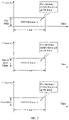
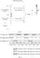
- FIG. 6 shows an example of a time unit in which three SR configurations (an SR configuration #0, an SR configuration #1, and an SR configuration #2) configured by the network device are located.
- a time unit in which the SR configuration #0 is located is a symbol #0, a symbol #2, a symbol #4, and a symbol #6. This indicates that the terminal device can send, on the four symbols, an SR associated with the SR configuration #0.
- the example is merely used to explain the embodiments of this application, and shall not be construed as any limitation.
- a time unit in which the terminal device reports an SR is configured by the network device, or configured by using higher layer signaling, or configured by the terminal device, generating an SR is behavior of the terminal device; therefore, the network device knows only that an SR associated with a specific SR configuration may exist in a specific time unit, but does not know which SR associated with SR configuration is actually reported by the terminal device in this specific time unit. To make the network device know which SR configuration actually reported by the terminal device in this specific time unit is associated with the SR, the terminal device needs to send an SR bit to the network device.
- the terminal device may determine, according to an actual requirement, to report, on the symbol #0, only the SR associated with the SR configuration #0 and not to report an SR associated with the SR configuration #1.
- the terminal device sends two SR bits " 10" to the network device, so that the network device can know, based on the two SR bits "10", that the terminal device actually reports, on the symbol #0, only the SR associated with the SR configuration #0 and does not report the SR associated with the SR configuration #1.
- the terminal device may determine, according to an actual requirement, to report, on the symbol #0, the SR associated with the SR configuration #0 and an SR associated with the SR configuration #1.
- a most significant bit "1" is used to indicate whether the SR associated with the SR configuration #0 is a positive SR or a negative SR
- a least significant bit "0" is used to indicate whether the SR associated with the SR configuration #1 is a positive SR or a negative SR.
- the network device can know, based on the two SR bits "10", that the terminal device actually reports the SR associated with the SR configuration #0 and the SR associated with the SR configuration #1 on the symbol #0.
- the example is merely used to explain this application, and shall not be construed as any limitation.
- the quantity of the plurality of SR configurations is greater than or equal to 2.
- the quantity of the plurality of SR configurations is equal to a quantity of all SR configurations.
- the plurality of SR configurations may be all SR configurations dynamically configured by the network device for the terminal, or may be all SR configurations configured by the network device for the terminal by using higher layer signaling, or may be all SR configurations configured by another terminal device for the terminal.
- all SR configurations configured by the network device for the terminal device are: an SR configuration #0, an SR configuration #1, and an SR configuration #2.
- a quantity of all the SR configurations configured by the network device for the terminal is 3. It can be learned, from FIG. 8 , that some SR configurations in all the SR configurations may be separately used in each time unit (symbol).
- a first bit(s) is used to indicate an SR(s) associated with at least one SR configuration in all the SR configurations.
- the SR configuration #0 and the SR configuration #1 are used on a symbol #0, and the first bit(s) is used to indicate an SR associated with the SR configuration #0 and/or the SR configuration #1 in all the SR configurations; and the SR configuration #2 is used on a symbol #1, and the first bit(s) is used to indicate an SR associated with the SR configuration #2 in all the SR configurations.
- the example is merely used to explain this application, and shall not be construed as any limitation.
- the plurality of SR configurations may be SR configurations in the time unit that are dynamically configured by the network device for the terminal, or may be SR configurations in the time unit that are configured by the network device for the terminal by using higher layer signaling, or may be SR configurations in the time unit that are configured by another terminal for the terminal.
- SR configurations on a symbol #0 that are configured by the network device for the terminal device are: an SR configuration #0 and an SR configuration #1.
- a quantity of SR configurations on the symbol #0 that are configured by the network device for the terminal is 2, and a first bit(s) is used to indicate an SR(s) associated with at least one SR configuration in the SR configuration #0 and the SR configuration #1.
- an SR configuration that is configured by the network device for the terminal device and that is on a symbol #1 is an SR configuration #2.
- a quantity of SR configurations on the symbol #1 that are configured by the network device for the terminal is 1, and a first bit(s) is used to indicate an SR(s) associated with an SR configuration #2.
- the examples are merely used to explain this application, and shall not be construed as any limitation.
- SR configurations in one time unit that are configured for the terminal may include SR configurations associated with different uplink control channel attributes.
- SR configurations associated with different uplink control channel attributes For details about an uplink control channel attribute associated with an SR configuration, refer to description of a subsequent manner 4. Explanation is not given herein.
- the quantity of the plurality of SR configurations is equal to a quantity of SR configurations in a plurality of time units.
- the plurality of SR configurations may be SR configurations that are dynamically configured by the network device for the terminal and that are in a plurality of time units, or may be SR configurations that are configured by the network device for the terminal by using higher layer signaling and that are in a plurality of time units, or may be SR configurations that are configured by another terminal for the terminal and that are in a plurality of time units.
- the plurality of time units include one time unit in which the terminal sends the hybrid automatic repeat request bit(s) and the first bit(s).
- SR configurations on a symbol #0 that are configured by the network device for the terminal device are: an SR configuration #0 and an SR configuration #1; and an SR configuration that is configured by the network device for the terminal device and that is on a symbol #1 is an SR configuration #2.
- total SR configurations that are configured by the network device for the terminal and that are on the symbol #0 and a symbol #1 are: the SR configuration #0, the SR configuration #1, and the SR configuration #2.
- a quantity of SR configurations that are configured by the network device for the terminal and that are on the symbol #0 and the symbol #1 is 3, and a first bit(s) is used to indicate an SR(s) associated with at least one SR configuration in the SR configuration #0, the SR configuration #1, and the SR configuration #2.
- the example is merely used to explain this application, and shall not be construed as any limitation.
- the plurality of time units are consecutive. This application is not limited thereto, and the plurality of time units may alternatively be inconsecutive.
- SR configurations on a symbol #0 that are configured by the network device for the terminal device are: an SR configuration #0 and an SR configuration #1; and an SR configuration that is configured by the network device for the terminal device and that is on a symbol #2 is an SR configuration #0.
- total SR configurations that are configured by the network device for the terminal on the symbol #0 and the symbol #2 are: the SR configuration #0 and the SR configuration #1.
- a quantity of SR configurations that are configured by the network device for the terminal and that are on the symbol #0 and the symbol #2 is 2, and a first bit(s) is used to indicate an SR associated with at least one SR configuration in the SR configuration #0 and the SR configuration #1.
- the example is merely used to explain this application, and shall not be construed as any limitation.
- SR configurations that are configured for the terminal and that are in a plurality of time units may include SR configurations associated with different uplink control channel attributes.
- SR configurations associated with different uplink control channel attributes For details about an uplink control channel attribute associated with an SR configuration, refer to description of a subsequent manner 4. Explanation is not given herein.
- the quantity of the plurality of SR configurations is equal to a quantity of SR configurations that are associated with a same uplink control channel attribute and that are in one or more time units.
- the plurality of SR configurations may be SR configurations that are dynamically configured by the network device for the terminal and that are in one or more time units and associated with a same uplink control channel attribute, or may be SR configurations that are configured by the network device for the terminal by using higher layer signaling and that are in one or more time units and associated with a same uplink control channel attribute, or may be SR configurations that are configured by another terminal for the terminal and that are in one or more time units and associated with a same uplink control channel attribute.
- an uplink control channel attribute associated with an SR configuration is an attribute of an uplink control channel that carries an SR.
- An attribute of an uplink control channel may include at least one of the following: a length of a time unit occupied by the uplink control channel, or a quantity of time units occupied by the uplink control channel, or a format of the uplink control channel, or a minimum quantity or a maximum quantity of bits carried by the uplink control channel.
- a single time unit (for example, one time unit is one symbol) is used as an example.
- SR configurations on a symbol #0 that are configured by the network device for the terminal device are: an SR configuration #0, an SR configuration #1, and an SR configuration #3.
- the SR configuration #0 and the SR configuration #1 are associated with a same uplink control channel attribute, and the same uplink control channel attribute is one symbol.
- a length of a time unit that carries an SR associated with the SR configuration #0 is one symbol
- a length of a time unit that carries an SR associated with the SR configuration #1 is also one symbol.
- An uplink control channel attribute associated with the SR configuration #3 is one mini-slot (mini-slot) (namely, four symbols).
- a length of a time unit that carries an SR associated with the SR configuration #3 is four symbols or one mini-slot.
- SR configurations on the symbol #0 that are configured by the network device for the terminal device are the SR configuration #0 and the SR configuration #1, and do not include the SR configuration #3.
- a quantity of SR configurations that are configured by the network device for the terminal and that are on the symbol #0 and associated with the one-symbol uplink control channel attribute is 2, and in this case, a first bit(s) is used to indicate an SR(s) associated with at least one SR configuration in the SR configuration #0 and the SR configuration #1.
- an SR configuration that is configured by the network device for the terminal device and that is on the symbol #0 is the SR configuration #3, and does not include the SR configuration #0 or the SR configuration #1.
- a quantity of SR configurations on the symbol #0 that are configured by the network device for the terminal and that are associated with the one-mini-slot uplink control channel attribute is 1, and in this case, a first bit(s) is used to indicate an SR(s) associated with the SR configuration #3.
- a plurality of time units (for example, one time unit is one symbol) are used as an example.
- SR configurations that are configured by the network device for the terminal device and that are on a symbol #0 to a symbol #3 are: an SR configuration #0, an SR configuration #1, an SR configuration #2, and an SR configuration #3.
- the SR configuration #0, the SR configuration #1, and the SR configuration #2 are associated with a same uplink control channel attribute, and the same uplink control channel attribute is one symbol.
- An uplink control channel attribute associated with the SR configuration #3 is one mini-slot (mini-slot) (namely, four symbols).
- SR configurations that are configured by the network device for the terminal device and that are on the symbol #0 to the symbol #3 are the SR configuration #0, the SR configuration #1, and the SR configuration #2, and do not include the SR configuration #3.
- a quantity of SR configurations that are configured by the network device for the terminal and that are on the symbol #0 to the symbol #3 and associated with the one-symbol uplink control channel attribute is 3, and in this case, a first bit(s) is used to indicate an SR associated with at least one SR configuration in the SR configuration #0, the SR configuration #1, and the SR configuration #2.
- an SR configuration that is configured by the network device for the terminal device and that is on the symbol #0 to the symbol #4 is the SR configuration #3, and does not include the SR configuration #0, the SR configuration #1, and the SR configuration #2.
- a quantity of SR configurations that are configured by the network device for the terminal and that are on the symbol #0 to the symbol #4 and associated with the one-mini-slot uplink control channel attribute is 1, and in this case, a first bit(s) is used to indicate an SR(s) associated with the SR configuration #3.
- the plurality of time units may be consecutive, or may be inconsecutive.
- Manner 4 is described merely by using an example in which an uplink control channel attribute is a length of a time unit occupied by an uplink control channel. For another uplink control channel attribute, similar processing applies.
- a quantity of time units occupied by an uplink control channel is the same as a quantity of time units occupied by another uplink control channel, for example, both are two time units, it is considered that attributes of the uplink control channels are the same. Otherwise, the attributes are different.
- a format of an uplink control channel is the same as that of another uplink control channel, for example, both are uplink control channels in a first format, it is considered that attributes of the uplink control channels are the same. Otherwise, the attributes are different.
- a minimum quantity of bits that can be carried by an uplink control channel is the same as a minimum quantity of bits that can be carried by another uplink control channel, for example, both are two bits, it is considered that attributes of the uplink control channels are the same. Otherwise, the attributes are different.
- a maximum quantity of bits that can be carried by an uplink control channel is the same as a maximum quantity of bits that can be carried by another uplink control channel, for example, both are two bits, it is considered that attributes of the uplink control channels are the same. Otherwise, the attributes are different.
- An operation manner applicable when the attributes are the same or different is similar to a manner for a length of a time unit occupied by an uplink control channel.
- a quantity of SR configurations is a quantity of SR configurations associated with a same attribute. Therefore, details are not described herein again.
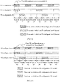
- a location relationship between an SR bit(s) and a HARQ bit(s) in a bit sequence may include but is not limited to the following:
- FIG. 13A to FIG. 13 E show only a concatenation relationship between an SR bit(s) and a HARQ bit(s) in an original bit sequence prior to coding.
- this application does not impose any particular limitation on other bits in (3) and (4), which may be any other bits prior to coding.
- a time unit may be a symbol (symbol), a slot (slot), a mini-slot (mini-slot), or a subframe (subframe).
- symbols symbols
- slot slot
- mini-slot mini-slot
- subframe subframe
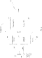
- the signal transmission method provided in this application may include the following steps.
- a terminal device generates a first bit(s).
- the first bit(s) is the foregoing SR bit(s), and may be used to indicate a scheduling request(s) associated with a first scheduling request configuration(s).
- the first scheduling request configuration(s) may be at least one of a plurality of scheduling request configurations configured by a network device for the terminal device.
- the generating, by a terminal device, a first bit(s) may include at least one of the following actions: (1) determining a quantity of first bit(s), and perform channel coding on the first bit(s); and (2) determining a bit state of the first bit(s), and determine the first bit(s) based on an attribute of a resource that needs to be requested.
- the at least one scheduling request configuration in the plurality of scheduling request configurations may be dynamically configured by the network device, or configured by the network device by using higher layer signaling.
- the higher layer signaling may be media access control (Media Access Control, MAC) layer signaling or radio resource control (Radio Resource Control, RRC) layer signaling.
- the at least one scheduling request configuration may be at least one of a plurality of scheduling request configurations dynamically configured by the network device for the terminal device, or the at least one scheduling request configuration may be at least one of a plurality of scheduling request configurations configured by the network device for the terminal by using higher layer signaling.
- the terminal device generates a hybrid automatic repeat request bit(s).
- the hybrid automatic repeat request bit(s) is used to feed back a result of decoding one or more downlink data blocks by the terminal device, and the result may be a positive acknowledgment ACK or a negative acknowledgment ACK.
- the ACK indicates that the terminal has correctly performed the decoding.
- the NACK indicates that an error has occurred during the decoding by the terminal. It may be understood that, if the terminal feeds back a negative acknowledgment, the network device retransmits data for which an error has occurred during the decoding by the terminal.
- the generating, by the terminal device, a HARQ bit(s) may include at least one of the following actions: determining a quantity of HARQ bit(s), and performing channel coding on the HARQ bit(s); and determining a bit state of the HARQ bit(s), and determining the HARQ bit(s) based on a downlink data reception status.
- the terminal device sends the hybrid automatic repeat request bit(s) and the first bit(s) in one time unit.
- the network device may receive the hybrid automatic repeat request bit(s) and the first bit(s) from the terminal device in the time unit.
- the network device may determine, based on the first bit(s), the scheduling request(s) associated with the first scheduling request configuration(s).
- the network device may determine, based on a state of each bit in the first bit(s), an SR (a positive SR or a negative SR) associated with an SR configuration corresponding to each bit.
- the network device may determine that the scheduling request associated with the first scheduling request configuration(s) is a negative SR associated with an SR configuration #0. If the first bits actually transmitted are "X1XX”, the network device may determine that the scheduling request associated with the first scheduling request configuration is a positive SR associated with an SR configuration #1.
- Table 5 a possible state of each bit in the first bit(s) and a possible SR configuration corresponding to each bit are shown in Table 5. If the first bits actually transmitted are "0XXX", the network device may determine that the scheduling request associated with the first scheduling request configuration(s) is a negative SR associated with an SR configuration #0. If the first bits actually transmitted are "X1XX”, the network device may determine that the scheduling request associated with the first scheduling request configuration is a positive SR associated with an SR configuration #1.
- the example is merely used to explain this application, and shall not be construed as any limitation.
- the network device may determine, based on a state of a first bit(s), an SR (a positive SR or a negative SR) corresponding to the state.
- first bits actually transmitted are "001"
- the network device may determine that the scheduling request associated with the first scheduling request configuration(s) is a positive SR associated with an SR configuration #0. If the first bits actually transmitted are "000”, the network device may determine that the scheduling request associated with the first scheduling request configuration(s) is: negative SRs associated with SR configurations #0, #1, #2, and #3, in other words, SRs associated with all the SR configurations are negative SRs.
- S101 there may be another time sequence of S101 and S102.
- S102 is performed before S101. This is not limited in this application.
- one bit in the SR bit(s) (namely, the first bit(s)) is used to indicate a scheduling request(s) associated with one SR configuration in the at least one SR configuration (namely, first SR configuration(s)).
- a first SR configuration(s) corresponds to a bit(s) in the SR bit(s).
- one SR configuration corresponds to one bit in the SR bit(s).
- a quantity O SR of the SR bits is equal to a quantity of the plurality of SR configurations (namely, the plurality of SR configurations mentioned in the foregoing invention principles) configured for the terminal.
- One bit in the SR bit(s) is used to indicate whether an SR associated with one SR configuration in the first SR configuration(s) is a positive SR or a negative SR. Specifically, one bit in the SR bit(s) is used to indicate whether an SR associated with one SR configuration corresponding to the bit is a positive SR or a negative SR. For example, it is assumed that one bit in the SR bit(s) corresponds to an SR configuration #0. Table 4 shows the bit and an indication meaning of the bit. Table 4 Bit state Indication meaning of a bit (a corresponding SR configuration, and an SR associated with the SR configuration) 0 Negative SR associated with an SR configuration #0 1 Positive SR associated with an SR configuration #0
- the left column in Table 4 represents a state ("0" or "1") of the bit
- the right column in Table 4 represents an SR indicated by the bit.
- the state of the bit is "0" it indicates that the SR indicated by the bit is a negative SR associated with the SR configuration #0; or when the state of the bit is "1", it indicates that the SR indicated by the bit is a positive SR associated with the SR configuration #0.
- Table 4 is merely intended to explain this application. In practical application, a correspondence between the state of the bit and the SR indicated by the bit may be contrary to that shown in Table 4, and this is not limited herein.
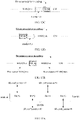
- the four SR bits respectively correspond to four different SR configurations: an SR configuration #3, an SR configuration #2, an SR configuration #1, and an SR configuration #0.
- the four SR bits may respectively correspond, in an order from a most significant bit to a least significant bit, to an SR configuration #3, an SR configuration #2, an SR configuration #1, and an SR configuration #0.
- the four SR bits may respectively correspond, in an order from a least significant bit to a most significant bit, to an SR configuration #3, an SR configuration #2, an SR configuration #1, and an SR configuration #0.
- the four SR bits may correspond to four different SR configurations in another manner, and this is not limited herein.
- a correspondence similar to a correspondence that is shown in FIG. 14A or FIG. 14B and that is between an SR configuration and a bit in the SR bits may be dynamically configured by a network device, or may be configured by a network device by using higher layer signaling.
- the correspondence may include B SR configurations, and B bits respectively corresponding to the B SR configurations.
- a terminal device may determine, based on the correspondence, each bit corresponding to each SR configuration of the at least one SR configuration (namely, first SR configuration(s)) in the SR bits.
- B is a positive integer.
- the correspondence configured by the network device or configured by using higher layer signaling may be referred to as a first correspondence.
- Table 5 shows an example of an indication meaning of each bit in the SR bits.
- Table 5 State Indication meaning of bits 0XXX Negative SR associated with an SR configuration #0 1XXX Positive SR associated with an SR configuration #0 X0XX Negative SR associated with an SR configuration #1 X1XX Positive SR associated with an SR configuration #1 XX0X Negative SR associated with an SR configuration #2 XX1X Positive SR associated with an SR configuration #2 XXX0 Negative SR associated with an SR configuration #3 XXX1 Positive SR associated with an SR configuration #3
- row 1 and row 2 represent the first most significant bit of the SR bits and a meaning of the bit.
- a state of the bit is "0" it indicates that an SR indicated by the bit is a negative SR associated with an SR configuration #0, in other words, an SR associated with an SR configuration #0 reported by a terminal is a negative scheduling request; or when a state of the bit is "1", it indicates that an SR indicated by the bit is a positive SR associated with an SR configuration #0, in other words, an SR associated with an SR configuration #0 reported by a terminal is a positive scheduling request.
- X in row 1 and row 2 means that, whether a state of any other bit is 0 or 1 does not affect a correspondence between the first bit and the SR configuration #0, and does not affect indication, by the first bit, of whether the SR associated with the SR configuration #0 is a positive SR or a negative SR.
- every two rows of the rest rows in Table 5 represent a bit in the SR bits and an indication meaning of the bit, and details are not described herein again.
- SRs are: a negative SR associated with an SR configuration #0, a negative SR associated with an SR configuration #1, a positive SR associated with an SR configuration #2, and a positive SR associated with an SR configuration #3.
- the terminal device actually reports two positive SRs: a positive SR associated with an SR configuration #2, and a positive SR associated with an SR configuration #3.
- values of a plurality of other bits in the SR bits are "1” it indicates that the terminal device actually reports positive SRs associated with a plurality of other SR configurations.
- the bit state of the SR bits is "1111" it indicates that the SR bits allow the terminal device to simultaneously report positive SRs associated with a maximum of four different SR configurations.
- one SR configuration corresponds to one bit in the SR bits.
- one SR configuration may alternatively correspond to a plurality of bits in the SR bits.
- a plurality of bits may be used to indicate an SR associated with one SR configuration.
- a quantity O SR of the SR bits is equal to an integer multiple of a quantity of SR configurations (namely, the plurality of SR configurations mentioned in the foregoing invention principles) configured by the network device for the terminal.
- This is another manner in which the quantity O SR of the SR bits is related to the quantity of the SR configurations configured by the network device for the terminal.
- two most significant bits of the SR bits are used to indicate an SR associated with an SR configuration #0.
- a state of the two bits is "00", it indicates that the SR indicated by the two bits is a negative SR associated with the SR configuration #0; or when a state of the two bits is a non-zero state ("01", or "10", or "11"), it indicates that the SR indicated by the two bits is a positive SR associated with the SR configuration #0.
- the example is merely an implementation provided in this application and shall not be construed as any limitation, and the implementation may vary in practical application.
- a plurality of non-zero states may be used to indicate a plurality of available attributes (for example, a TTI) of an uplink control channel that carries an SR, so as to instruct the network device to select one attribute from the plurality of attributes, thereby adapting to a scenario of a plurality of uplink control channel attributes in SR management.
- a plurality of available attributes for example, a TTI
- a bit state of an SR bit(s) (namely, a first bit(s)) is used to indicate a scheduling request(s) associated with the at least one SR configuration (namely, first SR configuration(s)).
- the SR positive SR or negative SR associated with the first SR configuration(s) corresponds to the state of the SR bit(s).
- a first state of the SR bit(s) is used to indicate that the SR(s) associated with the first SR configuration(s) is a negative SR(s).
- At least one state of the SR bit(s) other than the first state is used to indicate that the SR(s) associated with the first SR configuration(s) is a positive SR(s).
- no state of the SR bit(s) other than the first state is used to indicate that any one of the SR(s) associated with the first SR configuration(s) is a negative SR.
- only one state corresponds to a negative SR associated with the first SR configuration(s).
- the only one state is used to indicate that the SRs associated with the first SR configuration(s) are all negative SRs.
- at least one state other than the only state is not used to indicate that any one of the SRs associated with the first SR configuration(s) is a negative SR.
- the at least one state other than the only one state corresponds to a positive SR(s) associated with at least one SR configuration in the first SR configuration(s).
- the at least one state other than the only one state is used to indicate a positive SR(s) associated with at least one SR configuration.
- the only state may be referred to as a first state.
- Table 6-1 and Table 6-2 show examples of an indication meaning of each state of the SR bits.
- Table 6-1 Bit state Indication meaning of bits 000 Negative SRs associated with SR configurations #0, #1, #2, and #3 001 Positive SR associated with an SR configuration #0 010 Positive SR associated with an SR configuration #1 011 Positive SR associated with an SR configuration #2 Bit state Indication meaning of bits 100 Positive SR associated with an SR configuration #3 101 Reserved 110 Reserved 111 Reserved Table 6-2 Bit state Indication meaning of bits 000 Negative SRs associated with SR configurations #0, #1, #2, and #3 001 Positive SR associated with an SR configuration #0 010 Positive SR associated with an SR configuration #1 011 Positive SR associated with an SR configuration #2 100 Positive SR associated with an SR configuration #3 101 Positive SRs associated with an SR configuration #0 and an SR configuration #1 110 Positive SRs
- the state of the SR bits When the state of the SR bits is "000", it indicates that SRs associated with SR configurations #0, #1, #2, and #3 are all negative SRs. In other states of the SR bits, at least one state represents a positive SR associated with at least one SR configuration. For details, refer to Table 6-1 and Table 6-2.
- an amount of information carried by an uplink control channel may be reduced by indicating, by using a relatively small quantity of bits, each SR associated with the at least one SR configuration (namely, first SR configuration(s)), thereby improving a transmission success rate of the uplink control channel.
- a correspondence similar to a correspondence that is shown in Table 6-1 or Table 6-2 and that is between an SR and a state of the SR bits may be dynamically configured by a network device, or may be configured by a network device by using higher layer signaling.
- the correspondence may include SRs associated with P SR configurations, and Q states corresponding to the SRs associated with the P SR configurations.
- a terminal may determine, based on the correspondence, a state corresponding to an SR associated with the at least one SR configuration (namely, first SR configuration(s)).
- Q ⁇ 3 Q is a positive integer
- P ⁇ 2 is a positive integer.
- the correspondence may be referred to as a second correspondence.
- N configuration represents a quantity of SR configurations (namely, the plurality of SR configurations mentioned in the foregoing invention principles) configured for the terminal, and ceil represents rounding up to a next integer.
- a state of the SR bits may alternatively be used to indicate SRs associated with a plurality of SR configurations.
- a state "101" in Table 6-2 is used to indicate a positive SR associated with an SR configuration #0 and a positive SR associated with an SR configuration #1.
- the terminal device reports a positive SR associated with an SR configuration #0 and a positive SR associated with an SR configuration #1.
- this is equivalent to reporting of a negative SR associated with an SR configuration #2 and a negative SR associated with an SR configuration #3.
- a state "110" in Table 6-2 may be used to indicate a positive SR associated with an SR configuration #3 and a positive SR associated with an SR configuration #2; and a state “111" in Table 6-2 may be used to indicate a positive SR associated with an SR configuration #3, a positive SR associated with an SR configuration #2, a positive SR associated with an SR configuration #1, and a positive SR associated with an SR configuration #0.
- the example is merely used to explain this application, and shall not be construed as any limitation.
- an index of an SR configuration associated with one positive SR may be used as a maximum value, and SRs associated with SR configurations whose indices are less than the maximum value are all positive SRs.
- the terminal device can indicate, based on only a state of an SR bit corresponding to this positive SR, positive SRs associated with a plurality of SR configurations.
- a state of the SR bits is "100", used to indicate a positive SR associated with an SR configuration #3.
- the index "3" of the SR configuration #3 is used as a maximum value, and SRs respectively associated with an SR configuration #2, an SR configuration #1, and an SR configuration #0 whose indices are less than "3" are all positive SRs.
- the example is merely used to explain this application, and shall not be construed as any limitation.
- an index of an SR configuration associated with one positive SR may be used as a minimum value, and SRs associated with SR configurations whose indices are greater than the minimum value are all positive SRs.
- the terminal device can indicate, based on only a state of an SR bit corresponding to the positive SR, positive SRs associated with a plurality of SR configurations.
- a state of the SR bits is "001", used to indicate a positive SR associated with an SR configuration #1.
- the index "1" of the SR configuration #1 is used as a minimum value, and SRs respectively associated with an SR configuration #2 and an SR configuration #3 whose indices are greater than "1" are all positive SRs.
- the example is merely used to explain this application, and shall not be construed as any limitation.
- a quantity of HARQ bits sent along with the SR bit(s) is greater than or equal to X, X ⁇ 2, and X is a positive integer. This prevents affecting a transmission success rate for a small quantity of HARQ bits. This is because reliability of HARQ transmission design increases as the quantity of HARQ bits increases. In other words, when the quantity of HARQ bits is relatively small, it is not suitable to add a plurality of SR bits after a HARQ bit.
- a length of a current time unit is greater than or equal to Y symbols, Y ⁇ 1, and Y is a positive integer. This prevents affecting a transmission success rate of an uplink control channel in a time unit of a short length. This is because transmit power of an uplink control channel in a current time unit increases as a time length of a current time-domain resource increases, bringing higher reliability. In other words, when the time length of the current time unit is relatively small, it is not suitable for the uplink control channel in the current time unit to carry a plurality of SR bits.
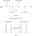
- FIG. 15 shows a wireless communications system, a terminal, and a network device according to this application.
- the wireless communications system 10 includes: a terminal 400 and a network device 500.
- the terminal 400 may be the terminal 200 in the embodiment in FIG. 4
- the network device 500 may be the network device 300 in the embodiment in FIG. 5
- the wireless communications system 10 may be the wireless communications system 100 described in FIG. 3 , as separately described below.
- the terminal 400 may include: a generation unit 401 and a sending unit 403.
- the generation unit 401 may be configured to generate a first bit(s).
- the first bit(s) may be used to indicate a scheduling request(s) associated with a first scheduling request configuration(s), and the first scheduling request configuration(s) may be at least one of a plurality of scheduling request configurations.
- the generation unit 401 may be further configured to generate a hybrid automatic repeat request bit(s).
- the sending unit 403 may be configured to send the hybrid automatic repeat request bit(s) and the first bit(s) in one time unit.
- a quantity of the plurality of scheduling request configurations may be equal to a quantity of scheduling request configurations in the time unit, or a quantity of the plurality of scheduling request configurations may be equal to a quantity of all scheduling request configurations.
- the first bit(s) may indicate, in the following manners, the scheduling request(s) associated with the first scheduling request configuration(s):
- one bit in the first bit(s) may be used to indicate a scheduling request(s) associated with one scheduling request configuration in first scheduling request configuration(s).
- a first state of the first bit(s) may be used to indicate that the scheduling request(s) associated with the first scheduling request configuration(s) is a negative scheduling request(s)
- at least one state of the first bit(s) other than the first state may be used to indicate that the scheduling request(s) associated with the first scheduling request configuration(s) is a positive scheduling request(s)
- no state of the first bit(s) other than the first state is used to indicate that any one of the scheduling request(s) associated with the first scheduling request configuration(s) is a negative scheduling request.
- a quantity of the first bit(s) may be related to the quantity of the plurality of scheduling request configurations, specifically in the following manners:
- a quantity O SR of the SR bits may be equal to the quantity of the plurality of scheduling request configurations.
- the network device and the terminal device can determine the quantity of the first bit(s) before the first bit(s) is sent, so that the network device and the terminal device do not have different understandings of the quantity of the first bit(s), thereby avoiding a case in which the first bit(s) fails to be received due to the different understandings.
- a quantity of HARQ bits sent along with the SR bit(s) is greater than or equal to X, X ⁇ 2, and X is a positive integer. This prevents affecting a transmission success rate for a small quantity of HARQ bits. This is because reliability of HARQ transmission design increases as the quantity of HARQ bits increases. In other words, when the quantity of HARQ bits is relatively small, it is not suitable to add a plurality of SR bits after a HARQ bit.
- a length of the time unit is greater than or equal to Y symbols, Y ⁇ 1, and Y is a positive integer. This prevents affecting a transmission success rate of an uplink control channel in a time unit of a short length. This is because transmit power of an uplink control channel in a current time unit increases as a time length of a current time-domain resource increases, bringing higher reliability. In other words, when the time length of the current time unit is relatively small, it is not suitable for the uplink control channel in the current time unit to carry a plurality of SR bits.
- the network device 500 may include: a receiving unit 501 and a determining unit 503.
- the receiving unit 501 may be configured to receive, in one time unit, a hybrid automatic repeat request bit(s) and a first bit(s) that are sent by a terminal device.
- the first bit(s) may be used to indicate a scheduling request(s) associated with a first scheduling request configuration(s), and the first scheduling request configuration(s) may be at least one of a plurality of scheduling request configurations.
- the determining unit 503 may be configured to determine, based on the first bit(s), the scheduling request(s) associated with the first scheduling request configuration(s).
- a quantity of the plurality of scheduling request configurations may be equal to a quantity of scheduling request configurations in the time unit, or a quantity of the plurality of scheduling request configurations may be equal to a quantity of all scheduling request configurations.
- the first bit(s) may indicate, in the following manners, the scheduling requests associated with the first scheduling request configuration(s):
- one bit in the first bit(s) may be used to indicate a scheduling request(s) associated with one scheduling request configuration in first scheduling request configuration(s).
- the determining unit 503 may be configured to determine, based on a state of each bit in the first bit(s), an SR (a positive SR or a negative SR) associated with an SR configuration corresponding to each bit.
- a first state of the first bit(s) may be used to indicate that the scheduling request(s) associated with the first scheduling request configuration(s) is a negative scheduling request(s)
- at least one state of the first bit(s) other than the first state may be used to indicate that the scheduling request(s) associated with the first scheduling request configuration(s) is a positive scheduling request(s)
- no state of the first bit(s) other than the first state is used to indicate that any one of the scheduling request(s) associated with the first scheduling request configuration(s) is a negative scheduling request.
- the determining unit 503 may be configured to determine, based on a state of the first bit(s), an SR (a positive SR or a negative SR) corresponding to the state.
- a quantity of the first bit(s) may be related to the quantity of the plurality of scheduling request configurations, specifically in the following manners:
- a quantity O SR of the SR bits may be equal to the quantity of the plurality of SR configurations.
- a quantity of HARQ bits sent along with the SR bit(s) is greater than or equal to X, X ⁇ 2, and X is a positive integer. This prevents affecting a transmission success rate for a small quantity of HARQ bits. This is because reliability of HARQ transmission design increases as the quantity of HARQ bits increases. In other words, when the quantity of HARQ bits is relatively small, it is not suitable to add a plurality of SR bits after a HARQ bit.
- a length of the time unit is greater than or equal to Y symbols, Y ⁇ 1, and Y is a positive integer. This prevents affecting a transmission success rate of an uplink control channel in a time unit of a short length. This is because transmit power of an uplink control channel in a current time unit increases as a time length of a current time-domain resource increases, bringing higher reliability. In other words, when the time length of the current time unit is relatively small, it is not suitable for the uplink control channel in the current time unit to carry a plurality of SR bits.
- FIG. 16 is a schematic structural diagram of an apparatus according to this application.
- the apparatus 50 may include: a processor 501, and one or more interfaces 502 coupled to the processor 501.
- the apparatus 50 may further include a memory 503.
- the apparatus 50 may be a chip.
- the processor 501 may be configured to read and execute a computer readable instruction.
- the processor 501 may mainly include a controller, an arithmetic unit, and a register.
- the controller is mainly responsible for decoding an instruction, and sending a control signal for an operation that corresponds to the instruction.
- the arithmetic unit is mainly responsible for performing a fixed-point or floating-point arithmetic operation, a shift operation, a logic operation, and the like; and may also perform address calculation and conversion.
- the register is mainly responsible for storing a register operand and an intermediate operation result to be temporarily stored in a process of executing an instruction, and the like.
- a hardware architecture of the processor 501 may be an application-specific integrated circuit (Application-Specific Integrated Circuit, ASIC) architecture, a MIPS architecture, an ARM architecture, an NP architecture, or the like.
- ASIC Application-Specific Integrated Circuit
- MIPS Micro-Integrated Circuit
- ARM Application-Specific Integrated Circuit
- NP Network-Nothing
- the processor 501 may be a single-core processor, or may be a multi-core processor.
- the memory 503 may be configured to store program code including a computer-accessible instruction, and may be further configured to store input/output data of the processor 501.
- the input/output interface 502 may be configured to input to-be-processed data to the processor 501, and may output a processing result of the processor 501.
- the interface 502 may be a general purpose input/output (General Purpose Input/Output, GPIO) interface, and may be connected to a plurality of peripheral devices (for example, a display (LCD), a camera, and a radio frequency module).
- the interface 502 may further include a plurality of independent interfaces, for example, an Ethernet interface, an LCD interface, and a camera interface, which are respectively responsible for communication between different peripheral devices and the processor 501.
- the processor 501 may be configured to invoke, from the memory, a program for implementing, on a terminal side, a signal transmission method provided in one or more embodiments of this application, and execute an instruction included in the program.
- the interface 502 may be configured to output an execution result of the processor 501.
- the interface 502 may be specifically configured to output a processing result of the processor 501.
- the processor 501 may be configured to generate a first bit(s) and a hybrid automatic repeat request bit(s), and the interface 502 may be configured to output the first bit(s) and the hybrid automatic repeat request bit(s).
- the signal transmission method provided in one or more embodiments of this application, refer to the foregoing embodiments. Details are not described herein again.
- functions respectively corresponding to the processor 501 and the interface 502 may be implemented by using hardware design, or may be implemented by using software design, or may be implemented by combining software and hardware, and this is not limited herein.
- FIG. 17 is a schematic structural diagram of an apparatus according to this application.
- the apparatus 60 may include: a processor 601, and one or more interfaces 601 coupled to the processor 602.
- the apparatus 60 may further include a memory 603.
- the apparatus 60 may be a chip.
- the processor 601 may be configured to read and execute a computer readable instruction.
- the processor 601 may mainly include a controller, an arithmetic unit, and a register.
- the controller is mainly responsible for decoding the instruction, and sending a control signal for an operation that corresponds to the instruction.
- the arithmetic unit is mainly responsible for performing a fixed-point or floating-point arithmetic operation, a shift operation, a logic operation, and the like; and may also perform address calculation and conversion.
- the register is mainly responsible for storing a register operand and an intermediate operation result to be temporarily stored in a process of executing the instruction, and the like.
- a hardware architecture of the processor 601 may be an application-specific integrated circuit (Application-Specific Integrated Circuit, ASIC) architecture, or the like.
- the processor 601 may be a single-core processor, or may be a multi-core processor.
- the memory 603 may be configured to store program code including a computer-accessible instruction, and may be further configured to store input/output data of the processor 601.
- the input/output interface 602 may be configured to input data to be processed to the processor 601, and may output a processing result of the processor 601.
- the processor 601 may be configured to: invoke, from the memory, a program for implementing, on a network device side, a signal transmission method provided in one or more embodiments of this application, and execute an instruction included in the program.
- the interface 602 may be configured to output an execution result of the processor 601.
- the processor 601 may be configured to determine, based on a first bit(s) from a terminal device, a scheduling request(s) associated with a first scheduling request configuration(s), and the interface 602 may be configured to output the scheduling request(s) that is determined by the processor 601 and that is associated with the first scheduling request configuration(s).
- the first scheduling request configuration(s), and the like refer to the foregoing embodiments. Details are not described herein again.
- functions respectively corresponding to the processor 601 and the interface 602 may be implemented by using hardware design, or may be implemented by using software design, or may be implemented by combining software and hardware, and this is not limited herein.
- a plurality of scheduling request configurations can be supported by implementing the foregoing solutions provided in this application, so as to adapt to a multi-service scenario in a communications system.
- the foregoing storage medium includes: any medium that can store program code, such as a ROM, a random access memory RAM, a magnetic disk, or an optical disc.
Landscapes
- Engineering & Computer Science (AREA)
- Signal Processing (AREA)
- Computer Networks & Wireless Communication (AREA)
- Quality & Reliability (AREA)
- Mobile Radio Communication Systems (AREA)
Claims (10)
- Signalübertragungsverfahren, durchgeführt in einer Endgerätevorrichtung, das Folgendes umfasst:
Erzeugen (S101) einer ersten Planungsanforderung-Bitsequenz bzw. SR-Bitsequenz, wobei eine Anzahl von Bits der ersten SR-Bitsequenz gleich ┌log 2 (1 + N)┐ ist, wobei ┌ ┐ eine Operation zum Aufrunden auf die nächste ganze Zahl repräsentiert und N eine Anzahl einer Vielzahl von SR-Konfigurationen ist, wobei eine SR-Konfiguration mindestens eines der Folgenden angibt:einen Zeitbereichsort einer SR, undeinen Frequenzbereichsort einer SR;wobei ein erster Zustand der ersten SR-Bitsequenz angibt, dass alle aus einer Vielzahl von SRs negative SRs sind;wobei ein zweiter Zustand der ersten SR-Bitsequenz angibt, dass eine erste SR eine positive SR ist und sich der zweite Zustand von dem ersten Zustand unterscheidet;wobei die erste SR eine SR aus einer Vielzahl von SRs ist, die erste SR mit einer ersten SR-Konfiguration assoziiert ist und die erste SR-Konfiguration eine aus der Vielzahl von SR-Konfigurationen ist;Erzeugen (S102) einer Hybrid-Automatische-Wiederholung-Anforderung-ACK/NACK-Bitsequenz bzw. HARQ-ACK/NACK-Bitsequenz; undSenden (S103) der HARQ-ACK/NACK-Bitsequenz und der ersten SR-Bitsequenz durch einen Uplink-Steuerkanal. - Signalübertragungsverfahren, durchgeführt in einer Netzvorrichtung, das Folgendes umfasst:
Empfangen (S103) einer Hybrid-Automatische-Wiederholung-Anforderung-ACK/NACK-Bitsequenz bzw. HARQ-ACK/NACK-Bitsequenz und einer ersten Planungsanforderung-Bitsequenz bzw. SR-Bitsequenz durch einen Uplink-Steuerkanal, wobei eine Anzahl von Bits der ersten SR-Bitsequenz gleich ┌log 2(1 + N)┐ ist, wobei ┌ ┐ eine Operation zum Aufrunden auf die nächste ganze Zahl repräsentiert und N eine Anzahl einer Vielzahl von SR-Konfigurationen ist, wobei eine SR-Konfiguration mindestens eines der Folgenden angibt:einen Zeitbereichsort einer SR, undeinen Frequenzbereichsort einer SR;wobei ein erster Zustand der ersten SR-Bitsequenz angibt, dass alle aus einer Vielzahl von SRs negative SRs sind;wobei ein zweiter Zustand der ersten SR-Bitsequenz angibt, dass eine erste SR eine positive SR ist und sich der zweite Zustand von dem ersten Zustand unterscheidet;wobei die erste SR eine SR aus einer Vielzahl von SRs ist, die erste SR mit einer ersten SR-Konfiguration assoziiert ist und die erste SR-Konfiguration eine aus der Vielzahl von SR-Konfigurationen ist; undBestimmen (S014), auf der Grundlage der ersten SR-Bitsequenz, der ersten SR, die mit der ersten SR-Konfiguration assoziiert ist. - Verfahren nach Anspruch 1 oder 2, wobei eine Kanalzustandsinformationen-Bitsequenz bzw. CSI-Bitsequenz an ein Ende der ersten SR-Bitsequenz angehängt wird und die erste SR-Bitsequenz an ein Ende der HARQ-Bitsequenz angehängt wird.
- Verfahren nach einem der Ansprüche 1 bis 3, wobei der erste Zustand ein Alles-Null-Zustand für alle Bits der ersten SR-Bitsequenz ist.
- Verfahren nach einem der Ansprüche 1 bis 4, wobei kein Zustand der ersten SR-Bitsequenz außer dem ersten Zustand angibt, dass irgendeine aus der Vielzahl von SRs eine negative SR ist.
- Verfahren nach Anspruch 5, wobei der zweite Zustand ,001' ist, ein dritter Zustand der ersten SR-Bitsequenz ,010' ist, ein vierter Zustand der ersten SR-Bitsequenz ,011' ist und ein fünfter Zustand der ersten SR-Bitsequenz ,100' ist,wobei der dritte Zustand angibt, dass eine zweite SR, die mit einer zweiten SR-Konfiguration assoziiert ist, eine positive SR ist, der vierte Zustand angibt, dass eine dritte SR, die mit einer dritten SR-Konfiguration assoziiert ist, eine positive SR ist, der fünfte Zustand angibt, dass eine vierte SR, die mit einer vierten SR-Konfiguration assoziiert ist, eine positive SR ist, und die zweite SR-Konfiguration, die dritte SR-Konfiguration und die vierte SR-Konfiguration drei SR-Konfigurationen aus der Vielzahl von SR-Konfigurationen sind,und wobei Indexnummern der ersten SR-Konfiguration, der zweiten SR-Konfiguration, der dritten SR-Konfiguration und der vierten SR-Konfiguration in aufsteigender Reihenfolge vorliegen.
- Einrichtung (50), wobei die Einrichtung dafür ausgelegt ist, ein Verfahren nach einem der Ansprüche 1 und 3 bis 6 auszuführen.
- Einrichtung (60), wobei die Einrichtung dafür ausgelegt ist, ein Verfahren nach einem der Ansprüche 2 und 3 bis 6 auszuführen.
- Computerlesbares Speicherungsmedium, das Anweisungen umfasst, die bei Ausführung durch einen Computer, den Computer veranlassen, ein Verfahren nach einem der Ansprüche 1 bis 6 auszuführen.
- Kommunikationssystem, das Folgendes umfasst:
eine Einrichtung nach Anspruch 7 und eine Einrichtung nach Anspruch 8.
Applications Claiming Priority (1)
| Application Number | Priority Date | Filing Date | Title |
|---|---|---|---|
| PCT/CN2017/101146 WO2019047193A1 (zh) | 2017-09-08 | 2017-09-08 | 信号传输方法、相关装置及系统 |
Publications (3)
| Publication Number | Publication Date |
|---|---|
| EP3675573A1 EP3675573A1 (de) | 2020-07-01 |
| EP3675573A4 EP3675573A4 (de) | 2020-09-09 |
| EP3675573B1 true EP3675573B1 (de) | 2022-03-30 |
Family
ID=65634688
Family Applications (1)
| Application Number | Title | Priority Date | Filing Date |
|---|---|---|---|
| EP17924437.1A Active EP3675573B1 (de) | 2017-09-08 | 2017-09-08 | Signalübertragungsverfahren, zugehörige vorrichtung und system |
Country Status (10)
| Country | Link |
|---|---|
| US (1) | US11006438B2 (de) |
| EP (1) | EP3675573B1 (de) |
| JP (1) | JP7189207B2 (de) |
| KR (1) | KR102304385B1 (de) |
| CN (2) | CN109757131B (de) |
| AU (1) | AU2017430542B2 (de) |
| BR (1) | BR112020004360A2 (de) |
| ES (1) | ES2914273T3 (de) |
| RU (1) | RU2744508C1 (de) |
| WO (1) | WO2019047193A1 (de) |
Families Citing this family (7)
| Publication number | Priority date | Publication date | Assignee | Title |
|---|---|---|---|---|
| BR112020004360A2 (pt) | 2017-09-08 | 2020-09-08 | Huawei Technologies Co., Ltd. | método de transmissão de sinal, aparelho relacionado, e sistema |
| CN109067512B (zh) * | 2017-09-08 | 2019-09-13 | 华为技术有限公司 | 信号传输方法、相关装置及系统 |
| CN111108796B (zh) * | 2017-09-28 | 2024-04-05 | 三星电子株式会社 | 用于在多个带宽部分上执行数据发射和测量的方法和网络节点 |
| CN110831219B (zh) * | 2018-08-10 | 2021-08-24 | 北京紫光展锐通信技术有限公司 | 业务冲突处理方法、用户终端及计算机可读存储介质 |
| EP4038847A1 (de) * | 2019-10-01 | 2022-08-10 | IDAC Holdings, Inc. | Verfahren und vorrichtungen zum senden und empfangen von daten in einem new-radio-system |
| US11968678B2 (en) * | 2021-04-06 | 2024-04-23 | Apple Inc. | UCI multiplexing with physical layer priority and LCH based prioritization |
| CN117119601A (zh) * | 2022-05-12 | 2023-11-24 | 中国移动通信有限公司研究院 | 资源请求方法、装置、通信设备及可读存储介质 |
Family Cites Families (34)
| Publication number | Priority date | Publication date | Assignee | Title |
|---|---|---|---|---|
| KR101376838B1 (ko) * | 2008-01-04 | 2014-03-20 | 엘지전자 주식회사 | 상향링크 제어신호 전송 방법 |
| ES2880704T3 (es) * | 2008-03-31 | 2021-11-25 | Ericsson Telefon Ab L M | Métodos y disposiciones en un sistema de telecomunicaciones |
| KR101715938B1 (ko) * | 2009-03-03 | 2017-03-14 | 엘지전자 주식회사 | 다중 안테나 시스템에서 harq ack/nack 신호 전송 방법 및 장치 |
| PL2908585T3 (pl) * | 2009-06-19 | 2017-12-29 | Interdigital Patent Holdings, Inc. | Sygnalizowanie informacji sterującej łączem wysyłania w LTE-A |
| US8327214B2 (en) | 2009-08-26 | 2012-12-04 | Ntt Docomo, Inc. | Method and apparatus for the joint design and operation of ARQ protocols with user scheduling for use with multiuser MIMO in the downlink of wireless systems |
| KR101328213B1 (ko) * | 2010-02-12 | 2013-11-14 | 엘지전자 주식회사 | 무선 통신 시스템에서 데이터 전송 방법 및 장치 |
| RU2560137C2 (ru) * | 2010-03-10 | 2015-08-20 | Эл Джи Электроникс Инк. | Способ и устройство для передачи управляющей информации восходящей линии связи в системе беспроводной связи |
| US9083495B2 (en) * | 2010-05-06 | 2015-07-14 | Telefonaktiebolaget Lm Ericsson (Publ) | System and method for signaling control information in a mobile communication network |
| EP2600549B1 (de) * | 2010-07-26 | 2019-09-04 | LG Electronics Inc. | Verfahren und vorrichtung zur übertragung von steuerinformationen |
| US20120084618A1 (en) * | 2010-10-01 | 2012-04-05 | Sharp Laboratories Of America, Inc. | Jointly encoding a scheduling request indicator and acknowledgments/negative acknowledgments |
| CN103238277A (zh) * | 2010-10-01 | 2013-08-07 | 捷讯研究有限公司 | 用于lte非周期性探测基准信号的跳频方法 |
| JP4927209B1 (ja) * | 2010-11-05 | 2012-05-09 | シャープ株式会社 | 無線通信システム、移動局装置、基地局装置、無線通信方法および集積回路 |
| KR20120119176A (ko) * | 2011-04-20 | 2012-10-30 | 주식회사 팬택 | 통신 시스템에서 제어신호 송수신 장치 및 방법 |
| US9215050B2 (en) | 2011-09-23 | 2015-12-15 | Lg Electronics Inc. | Method and apparatus for transmitting uplink control information in wireless communication system |
| CN103095398B (zh) * | 2011-11-04 | 2017-04-12 | 华为技术有限公司 | 传输控制信息的方法、用户设备和基站 |
| US20130121258A1 (en) * | 2011-11-14 | 2013-05-16 | Research In Motion Limited | Method and system for requesting a service utilizing a sequence of codes |
| CN103313368B (zh) * | 2012-03-16 | 2018-12-04 | 中兴通讯股份有限公司 | 物理上行控制信道的功率控制方法及用户设备 |
| WO2013138983A1 (en) * | 2012-03-19 | 2013-09-26 | Alcatel Lucent | Method and apparatus for configuring a plurality of scheduling request triggers |
| CN108616347B (zh) * | 2012-03-23 | 2021-01-22 | 联发科技股份有限公司 | 移动通信网络中分配调度请求资源的方法以及装置 |
| US9294230B2 (en) * | 2012-07-02 | 2016-03-22 | Intel Corporation | Multiplexing of channel state information and hybrid automatic repeat request—acknowledgement information |
| US9544801B2 (en) * | 2012-08-03 | 2017-01-10 | Intel Corporation | Periodic channel state information reporting for coordinated multipoint (coMP) systems |
| WO2014038901A1 (ko) * | 2012-09-09 | 2014-03-13 | 엘지전자 주식회사 | 데이터 송신 및 수신 방법 및 장치 |
| US20160119940A1 (en) * | 2013-05-15 | 2016-04-28 | Telefonaktiebolaget L M Ericsson (Publ) | Method and bs for identifying ue transmits sr, and method and ue for transmitting sr to bs |
| US20160270033A1 (en) * | 2013-10-14 | 2016-09-15 | Lg Electronics Inc. | Method for enhancing coverage in wireless communication system, and apparatus therefor |
| US10764912B2 (en) | 2014-10-13 | 2020-09-01 | Qualcomm Incorporated | Scheduling request modes for enhanced component carriers |
| US9775168B2 (en) * | 2015-05-19 | 2017-09-26 | Telefonaktiebolaget L M Ericsson (Publ) | Methods assigning resources for dedicated scheduling requests using MAC messages and related wireless terminals and base stations |
| CA2990574A1 (en) * | 2015-07-08 | 2017-01-12 | Sharp Kabushiki Kaisha | Terminal device, base station device, communication method, and integrated circuit |
| EP4120614B1 (de) * | 2016-01-06 | 2024-03-20 | Apple Inc. | Ul (uplink)-steuerungskonzept für unlizenziertes spektrum |
| EP3420657A4 (de) * | 2016-02-24 | 2019-10-02 | Intel IP Corporation | Physische uplink-steuerkanalformate für 5g |
| CN106793105B (zh) | 2016-08-26 | 2018-08-10 | 北京展讯高科通信技术有限公司 | 上行控制信息的传输方法、装置和用户终端 |
| EP3471489B1 (de) * | 2017-05-03 | 2023-03-29 | LG Electronics Inc. | Verfahren zum senden und empfangen von planungsanfragen zwischen einem endgerät und einer basisstation in einem drahtloskommunikationssystem und vorrichtung zur unterstützung davon |
| US11251923B2 (en) * | 2017-07-31 | 2022-02-15 | Qualcomm Incorporated | Uplink ACK/NACK and SR in short durations |
| BR112020004360A2 (pt) | 2017-09-08 | 2020-09-08 | Huawei Technologies Co., Ltd. | método de transmissão de sinal, aparelho relacionado, e sistema |
| CN109067512B (zh) * | 2017-09-08 | 2019-09-13 | 华为技术有限公司 | 信号传输方法、相关装置及系统 |
-
2017
- 2017-09-08 BR BR112020004360-5A patent/BR112020004360A2/pt active Search and Examination
- 2017-09-08 ES ES17924437T patent/ES2914273T3/es active Active
- 2017-09-08 RU RU2020112311A patent/RU2744508C1/ru active
- 2017-09-08 JP JP2020513806A patent/JP7189207B2/ja active Active
- 2017-09-08 AU AU2017430542A patent/AU2017430542B2/en active Active
- 2017-09-08 EP EP17924437.1A patent/EP3675573B1/de active Active
- 2017-09-08 WO PCT/CN2017/101146 patent/WO2019047193A1/zh not_active Ceased
- 2017-09-08 KR KR1020207009815A patent/KR102304385B1/ko active Active
- 2017-09-08 CN CN201780016039.4A patent/CN109757131B/zh active Active
- 2017-09-08 CN CN201910979971.8A patent/CN110868277B/zh active Active
-
2019
- 2019-12-31 US US16/731,737 patent/US11006438B2/en active Active
Also Published As
| Publication number | Publication date |
|---|---|
| CN110868277B (zh) | 2020-10-27 |
| KR102304385B1 (ko) | 2021-09-17 |
| EP3675573A4 (de) | 2020-09-09 |
| BR112020004360A2 (pt) | 2020-09-08 |
| AU2017430542B2 (en) | 2021-04-22 |
| WO2019047193A1 (zh) | 2019-03-14 |
| AU2017430542A1 (en) | 2020-04-02 |
| JP2020533863A (ja) | 2020-11-19 |
| EP3675573A1 (de) | 2020-07-01 |
| CN109757131A (zh) | 2019-05-14 |
| CN109757131B (zh) | 2021-07-16 |
| US11006438B2 (en) | 2021-05-11 |
| ES2914273T3 (es) | 2022-06-08 |
| CN110868277A (zh) | 2020-03-06 |
| KR20200044959A (ko) | 2020-04-29 |
| JP7189207B2 (ja) | 2022-12-13 |
| RU2744508C1 (ru) | 2021-03-11 |
| US20200137781A1 (en) | 2020-04-30 |
Similar Documents
| Publication | Publication Date | Title |
|---|---|---|
| US12199919B2 (en) | Feedback information transmission method and communication device | |
| US11006438B2 (en) | Signal transmission method, related apparatus, and system | |
| EP4436291A1 (de) | Kommunikationsverfahren und kommunikationsvorrichtung | |
| US12513689B2 (en) | Communication method and communication apparatus employing dynamic spectrum resource sharing | |
| US20220407629A1 (en) | Data transmission method and device | |
| JP2023542690A (ja) | ユーザ装置及びユーザ装置の方法 | |
| EP3605909B1 (de) | Verfahren zum senden von informationen und vorrichtung dafür und verfahren zum empfangen von informationen und vorrichtung dafür | |
| CA3109733A1 (en) | Harq feedback method and apparatus | |
| US20200396728A1 (en) | Communication Method And Communications Apparatus | |
| CN117499002B (zh) | 无线通信的方法、终端设备和网络设备 | |
| AU2018417481A1 (en) | Data transmission method, terminal device and network device | |
| WO2022021007A1 (zh) | 无线通信方法、终端设备和网络设备 | |
| EP4152845A1 (de) | Verfahren und vorrichtung zum senden und empfangen von sidelink-feedbackinformationen | |
| CN115399025B (zh) | 无线通信方法、终端设备和网络设备 | |
| WO2019192500A1 (zh) | 通信方法和通信装置 | |
| CN109067512B (zh) | 信号传输方法、相关装置及系统 | |
| KR20220002339A (ko) | 사용자 디바이스 및 그 무선 통신 방법 | |
| US20240237057A1 (en) | Wireless communication method, terminal device, and network device | |
| US20240163020A1 (en) | Communication method and storage medium | |
| CN117693915A (zh) | 基于子时隙1型码本改善harq-ack反馈的方法、基站和用户设备 | |
| US20250038815A1 (en) | Wireless communication methods, terminal devices and network devices | |
| US20230224908A1 (en) | Method for repeatedly transmitting control channel, terminal device, and network device |
Legal Events
| Date | Code | Title | Description |
|---|---|---|---|
| STAA | Information on the status of an ep patent application or granted ep patent |
Free format text: STATUS: THE INTERNATIONAL PUBLICATION HAS BEEN MADE |
|
| PUAI | Public reference made under article 153(3) epc to a published international application that has entered the european phase |
Free format text: ORIGINAL CODE: 0009012 |
|
| STAA | Information on the status of an ep patent application or granted ep patent |
Free format text: STATUS: REQUEST FOR EXAMINATION WAS MADE |
|
| 17P | Request for examination filed |
Effective date: 20200326 |
|
| AK | Designated contracting states |
Kind code of ref document: A1 Designated state(s): AL AT BE BG CH CY CZ DE DK EE ES FI FR GB GR HR HU IE IS IT LI LT LU LV MC MK MT NL NO PL PT RO RS SE SI SK SM TR |
|
| AX | Request for extension of the european patent |
Extension state: BA ME |
|
| A4 | Supplementary search report drawn up and despatched |
Effective date: 20200812 |
|
| RIC1 | Information provided on ipc code assigned before grant |
Ipc: H04W 72/04 20090101AFI20200806BHEP Ipc: H04L 5/00 20060101ALI20200806BHEP Ipc: H04L 1/00 20060101ALI20200806BHEP Ipc: H04L 1/16 20060101ALI20200806BHEP Ipc: H04W 72/12 20090101ALI20200806BHEP Ipc: H04L 1/18 20060101ALI20200806BHEP |
|
| DAV | Request for validation of the european patent (deleted) | ||
| DAX | Request for extension of the european patent (deleted) | ||
| RIC1 | Information provided on ipc code assigned before grant |
Ipc: H04W 72/04 20090101AFI20210511BHEP Ipc: H04W 72/12 20090101ALI20210511BHEP Ipc: H04L 1/00 20060101ALI20210511BHEP Ipc: H04L 1/16 20060101ALI20210511BHEP Ipc: H04L 1/18 20060101ALI20210511BHEP Ipc: H04L 5/00 20060101ALI20210511BHEP |
|
| GRAP | Despatch of communication of intention to grant a patent |
Free format text: ORIGINAL CODE: EPIDOSNIGR1 |
|
| STAA | Information on the status of an ep patent application or granted ep patent |
Free format text: STATUS: GRANT OF PATENT IS INTENDED |
|
| INTG | Intention to grant announced |
Effective date: 20210628 |
|
| GRAJ | Information related to disapproval of communication of intention to grant by the applicant or resumption of examination proceedings by the epo deleted |
Free format text: ORIGINAL CODE: EPIDOSDIGR1 |
|
| STAA | Information on the status of an ep patent application or granted ep patent |
Free format text: STATUS: REQUEST FOR EXAMINATION WAS MADE |
|
| INTC | Intention to grant announced (deleted) | ||
| GRAS | Grant fee paid |
Free format text: ORIGINAL CODE: EPIDOSNIGR3 |
|
| STAA | Information on the status of an ep patent application or granted ep patent |
Free format text: STATUS: GRANT OF PATENT IS INTENDED |
|
| GRAP | Despatch of communication of intention to grant a patent |
Free format text: ORIGINAL CODE: EPIDOSNIGR1 |
|
| INTG | Intention to grant announced |
Effective date: 20211007 |
|
| GRAA | (expected) grant |
Free format text: ORIGINAL CODE: 0009210 |
|
| STAA | Information on the status of an ep patent application or granted ep patent |
Free format text: STATUS: THE PATENT HAS BEEN GRANTED |
|
| AK | Designated contracting states |
Kind code of ref document: B1 Designated state(s): AL AT BE BG CH CY CZ DE DK EE ES FI FR GB GR HR HU IE IS IT LI LT LU LV MC MK MT NL NO PL PT RO RS SE SI SK SM TR |
|
| REG | Reference to a national code |
Ref country code: GB Ref legal event code: FG4D |
|
| REG | Reference to a national code |
Ref country code: CH Ref legal event code: EP |
|
| REG | Reference to a national code |
Ref country code: DE Ref legal event code: R096 Ref document number: 602017055401 Country of ref document: DE |
|
| REG | Reference to a national code |
Ref country code: AT Ref legal event code: REF Ref document number: 1480360 Country of ref document: AT Kind code of ref document: T Effective date: 20220415 |
|
| REG | Reference to a national code |
Ref country code: IE Ref legal event code: FG4D |
|
| REG | Reference to a national code |
Ref country code: ES Ref legal event code: FG2A Ref document number: 2914273 Country of ref document: ES Kind code of ref document: T3 Effective date: 20220608 |
|
| REG | Reference to a national code |
Ref country code: LT Ref legal event code: MG9D |
|
| PG25 | Lapsed in a contracting state [announced via postgrant information from national office to epo] |
Ref country code: SE Free format text: LAPSE BECAUSE OF FAILURE TO SUBMIT A TRANSLATION OF THE DESCRIPTION OR TO PAY THE FEE WITHIN THE PRESCRIBED TIME-LIMIT Effective date: 20220330 Ref country code: RS Free format text: LAPSE BECAUSE OF FAILURE TO SUBMIT A TRANSLATION OF THE DESCRIPTION OR TO PAY THE FEE WITHIN THE PRESCRIBED TIME-LIMIT Effective date: 20220330 Ref country code: NO Free format text: LAPSE BECAUSE OF FAILURE TO SUBMIT A TRANSLATION OF THE DESCRIPTION OR TO PAY THE FEE WITHIN THE PRESCRIBED TIME-LIMIT Effective date: 20220630 Ref country code: LT Free format text: LAPSE BECAUSE OF FAILURE TO SUBMIT A TRANSLATION OF THE DESCRIPTION OR TO PAY THE FEE WITHIN THE PRESCRIBED TIME-LIMIT Effective date: 20220330 Ref country code: HR Free format text: LAPSE BECAUSE OF FAILURE TO SUBMIT A TRANSLATION OF THE DESCRIPTION OR TO PAY THE FEE WITHIN THE PRESCRIBED TIME-LIMIT Effective date: 20220330 Ref country code: BG Free format text: LAPSE BECAUSE OF FAILURE TO SUBMIT A TRANSLATION OF THE DESCRIPTION OR TO PAY THE FEE WITHIN THE PRESCRIBED TIME-LIMIT Effective date: 20220630 |
|
| REG | Reference to a national code |
Ref country code: NL Ref legal event code: MP Effective date: 20220330 |
|
| REG | Reference to a national code |
Ref country code: AT Ref legal event code: MK05 Ref document number: 1480360 Country of ref document: AT Kind code of ref document: T Effective date: 20220330 |
|
| PG25 | Lapsed in a contracting state [announced via postgrant information from national office to epo] |
Ref country code: LV Free format text: LAPSE BECAUSE OF FAILURE TO SUBMIT A TRANSLATION OF THE DESCRIPTION OR TO PAY THE FEE WITHIN THE PRESCRIBED TIME-LIMIT Effective date: 20220330 Ref country code: GR Free format text: LAPSE BECAUSE OF FAILURE TO SUBMIT A TRANSLATION OF THE DESCRIPTION OR TO PAY THE FEE WITHIN THE PRESCRIBED TIME-LIMIT Effective date: 20220701 Ref country code: FI Free format text: LAPSE BECAUSE OF FAILURE TO SUBMIT A TRANSLATION OF THE DESCRIPTION OR TO PAY THE FEE WITHIN THE PRESCRIBED TIME-LIMIT Effective date: 20220330 |
|
| PG25 | Lapsed in a contracting state [announced via postgrant information from national office to epo] |
Ref country code: NL Free format text: LAPSE BECAUSE OF FAILURE TO SUBMIT A TRANSLATION OF THE DESCRIPTION OR TO PAY THE FEE WITHIN THE PRESCRIBED TIME-LIMIT Effective date: 20220330 |
|
| PG25 | Lapsed in a contracting state [announced via postgrant information from national office to epo] |
Ref country code: SM Free format text: LAPSE BECAUSE OF FAILURE TO SUBMIT A TRANSLATION OF THE DESCRIPTION OR TO PAY THE FEE WITHIN THE PRESCRIBED TIME-LIMIT Effective date: 20220330 Ref country code: SK Free format text: LAPSE BECAUSE OF FAILURE TO SUBMIT A TRANSLATION OF THE DESCRIPTION OR TO PAY THE FEE WITHIN THE PRESCRIBED TIME-LIMIT Effective date: 20220330 Ref country code: RO Free format text: LAPSE BECAUSE OF FAILURE TO SUBMIT A TRANSLATION OF THE DESCRIPTION OR TO PAY THE FEE WITHIN THE PRESCRIBED TIME-LIMIT Effective date: 20220330 Ref country code: PT Free format text: LAPSE BECAUSE OF FAILURE TO SUBMIT A TRANSLATION OF THE DESCRIPTION OR TO PAY THE FEE WITHIN THE PRESCRIBED TIME-LIMIT Effective date: 20220801 Ref country code: EE Free format text: LAPSE BECAUSE OF FAILURE TO SUBMIT A TRANSLATION OF THE DESCRIPTION OR TO PAY THE FEE WITHIN THE PRESCRIBED TIME-LIMIT Effective date: 20220330 Ref country code: CZ Free format text: LAPSE BECAUSE OF FAILURE TO SUBMIT A TRANSLATION OF THE DESCRIPTION OR TO PAY THE FEE WITHIN THE PRESCRIBED TIME-LIMIT Effective date: 20220330 Ref country code: AT Free format text: LAPSE BECAUSE OF FAILURE TO SUBMIT A TRANSLATION OF THE DESCRIPTION OR TO PAY THE FEE WITHIN THE PRESCRIBED TIME-LIMIT Effective date: 20220330 |
|
| PG25 | Lapsed in a contracting state [announced via postgrant information from national office to epo] |
Ref country code: PL Free format text: LAPSE BECAUSE OF FAILURE TO SUBMIT A TRANSLATION OF THE DESCRIPTION OR TO PAY THE FEE WITHIN THE PRESCRIBED TIME-LIMIT Effective date: 20220330 Ref country code: IS Free format text: LAPSE BECAUSE OF FAILURE TO SUBMIT A TRANSLATION OF THE DESCRIPTION OR TO PAY THE FEE WITHIN THE PRESCRIBED TIME-LIMIT Effective date: 20220730 Ref country code: AL Free format text: LAPSE BECAUSE OF FAILURE TO SUBMIT A TRANSLATION OF THE DESCRIPTION OR TO PAY THE FEE WITHIN THE PRESCRIBED TIME-LIMIT Effective date: 20220330 |
|
| REG | Reference to a national code |
Ref country code: DE Ref legal event code: R097 Ref document number: 602017055401 Country of ref document: DE |
|
| PG25 | Lapsed in a contracting state [announced via postgrant information from national office to epo] |
Ref country code: DK Free format text: LAPSE BECAUSE OF FAILURE TO SUBMIT A TRANSLATION OF THE DESCRIPTION OR TO PAY THE FEE WITHIN THE PRESCRIBED TIME-LIMIT Effective date: 20220330 |
|
| PLBE | No opposition filed within time limit |
Free format text: ORIGINAL CODE: 0009261 |
|
| STAA | Information on the status of an ep patent application or granted ep patent |
Free format text: STATUS: NO OPPOSITION FILED WITHIN TIME LIMIT |
|
| 26N | No opposition filed |
Effective date: 20230103 |
|
| PG25 | Lapsed in a contracting state [announced via postgrant information from national office to epo] |
Ref country code: MC Free format text: LAPSE BECAUSE OF FAILURE TO SUBMIT A TRANSLATION OF THE DESCRIPTION OR TO PAY THE FEE WITHIN THE PRESCRIBED TIME-LIMIT Effective date: 20220330 |
|
| REG | Reference to a national code |
Ref country code: CH Ref legal event code: PL |
|
| REG | Reference to a national code |
Ref country code: BE Ref legal event code: MM Effective date: 20220930 |
|
| PG25 | Lapsed in a contracting state [announced via postgrant information from national office to epo] |
Ref country code: SI Free format text: LAPSE BECAUSE OF FAILURE TO SUBMIT A TRANSLATION OF THE DESCRIPTION OR TO PAY THE FEE WITHIN THE PRESCRIBED TIME-LIMIT Effective date: 20220330 |
|
| P01 | Opt-out of the competence of the unified patent court (upc) registered |
Effective date: 20230524 |
|
| PG25 | Lapsed in a contracting state [announced via postgrant information from national office to epo] |
Ref country code: LU Free format text: LAPSE BECAUSE OF NON-PAYMENT OF DUE FEES Effective date: 20220908 |
|
| PG25 | Lapsed in a contracting state [announced via postgrant information from national office to epo] |
Ref country code: LI Free format text: LAPSE BECAUSE OF NON-PAYMENT OF DUE FEES Effective date: 20220930 Ref country code: IE Free format text: LAPSE BECAUSE OF NON-PAYMENT OF DUE FEES Effective date: 20220908 Ref country code: FR Free format text: LAPSE BECAUSE OF NON-PAYMENT OF DUE FEES Effective date: 20220930 Ref country code: CH Free format text: LAPSE BECAUSE OF NON-PAYMENT OF DUE FEES Effective date: 20220930 |
|
| PG25 | Lapsed in a contracting state [announced via postgrant information from national office to epo] |
Ref country code: BE Free format text: LAPSE BECAUSE OF NON-PAYMENT OF DUE FEES Effective date: 20220930 |
|
| PG25 | Lapsed in a contracting state [announced via postgrant information from national office to epo] |
Ref country code: CY Free format text: LAPSE BECAUSE OF FAILURE TO SUBMIT A TRANSLATION OF THE DESCRIPTION OR TO PAY THE FEE WITHIN THE PRESCRIBED TIME-LIMIT Effective date: 20220330 |
|
| PG25 | Lapsed in a contracting state [announced via postgrant information from national office to epo] |
Ref country code: MK Free format text: LAPSE BECAUSE OF FAILURE TO SUBMIT A TRANSLATION OF THE DESCRIPTION OR TO PAY THE FEE WITHIN THE PRESCRIBED TIME-LIMIT Effective date: 20220330 Ref country code: HU Free format text: LAPSE BECAUSE OF FAILURE TO SUBMIT A TRANSLATION OF THE DESCRIPTION OR TO PAY THE FEE WITHIN THE PRESCRIBED TIME-LIMIT; INVALID AB INITIO Effective date: 20170908 |
|
| PG25 | Lapsed in a contracting state [announced via postgrant information from national office to epo] |
Ref country code: TR Free format text: LAPSE BECAUSE OF FAILURE TO SUBMIT A TRANSLATION OF THE DESCRIPTION OR TO PAY THE FEE WITHIN THE PRESCRIBED TIME-LIMIT Effective date: 20220330 |
|
| PG25 | Lapsed in a contracting state [announced via postgrant information from national office to epo] |
Ref country code: MT Free format text: LAPSE BECAUSE OF FAILURE TO SUBMIT A TRANSLATION OF THE DESCRIPTION OR TO PAY THE FEE WITHIN THE PRESCRIBED TIME-LIMIT Effective date: 20220330 |
|
| PGFP | Annual fee paid to national office [announced via postgrant information from national office to epo] |
Ref country code: DE Payment date: 20250730 Year of fee payment: 9 |
|
| PGFP | Annual fee paid to national office [announced via postgrant information from national office to epo] |
Ref country code: IT Payment date: 20250825 Year of fee payment: 9 |
|
| PGFP | Annual fee paid to national office [announced via postgrant information from national office to epo] |
Ref country code: GB Payment date: 20250731 Year of fee payment: 9 |
|
| PGFP | Annual fee paid to national office [announced via postgrant information from national office to epo] |
Ref country code: ES Payment date: 20251016 Year of fee payment: 9 |