EP3675778B1 - Dispositifs prothétiques modulaires - Google Patents
Dispositifs prothétiques modulaires Download PDFInfo
- Publication number
- EP3675778B1 EP3675778B1 EP18850320.5A EP18850320A EP3675778B1 EP 3675778 B1 EP3675778 B1 EP 3675778B1 EP 18850320 A EP18850320 A EP 18850320A EP 3675778 B1 EP3675778 B1 EP 3675778B1
- Authority
- EP
- European Patent Office
- Prior art keywords
- chassis assembly
- module
- interchangeable module
- joint portion
- flanges
- Prior art date
- Legal status (The legal status is an assumption and is not a legal conclusion. Google has not performed a legal analysis and makes no representation as to the accuracy of the status listed.)
- Active
Links
Images






Classifications
-
- A—HUMAN NECESSITIES
- A61—MEDICAL OR VETERINARY SCIENCE; HYGIENE
- A61F—FILTERS IMPLANTABLE INTO BLOOD VESSELS; PROSTHESES; DEVICES PROVIDING PATENCY TO, OR PREVENTING COLLAPSING OF, TUBULAR STRUCTURES OF THE BODY, e.g. STENTS; ORTHOPAEDIC, NURSING OR CONTRACEPTIVE DEVICES; FOMENTATION; TREATMENT OR PROTECTION OF EYES OR EARS; BANDAGES, DRESSINGS OR ABSORBENT PADS; FIRST-AID KITS
- A61F2/00—Filters implantable into blood vessels; Prostheses, i.e. artificial substitutes or replacements for parts of the body; Appliances for connecting them with the body; Devices providing patency to, or preventing collapsing of, tubular structures of the body, e.g. stents
- A61F2/50—Prostheses not implantable in the body
- A61F2/78—Means for protecting prostheses or for attaching them to the body, e.g. bandages, harnesses, straps, or stockings for the limb stump
-
- A—HUMAN NECESSITIES
- A61—MEDICAL OR VETERINARY SCIENCE; HYGIENE
- A61F—FILTERS IMPLANTABLE INTO BLOOD VESSELS; PROSTHESES; DEVICES PROVIDING PATENCY TO, OR PREVENTING COLLAPSING OF, TUBULAR STRUCTURES OF THE BODY, e.g. STENTS; ORTHOPAEDIC, NURSING OR CONTRACEPTIVE DEVICES; FOMENTATION; TREATMENT OR PROTECTION OF EYES OR EARS; BANDAGES, DRESSINGS OR ABSORBENT PADS; FIRST-AID KITS
- A61F2/00—Filters implantable into blood vessels; Prostheses, i.e. artificial substitutes or replacements for parts of the body; Appliances for connecting them with the body; Devices providing patency to, or preventing collapsing of, tubular structures of the body, e.g. stents
- A61F2/50—Prostheses not implantable in the body
-
- A—HUMAN NECESSITIES
- A61—MEDICAL OR VETERINARY SCIENCE; HYGIENE
- A61F—FILTERS IMPLANTABLE INTO BLOOD VESSELS; PROSTHESES; DEVICES PROVIDING PATENCY TO, OR PREVENTING COLLAPSING OF, TUBULAR STRUCTURES OF THE BODY, e.g. STENTS; ORTHOPAEDIC, NURSING OR CONTRACEPTIVE DEVICES; FOMENTATION; TREATMENT OR PROTECTION OF EYES OR EARS; BANDAGES, DRESSINGS OR ABSORBENT PADS; FIRST-AID KITS
- A61F2/00—Filters implantable into blood vessels; Prostheses, i.e. artificial substitutes or replacements for parts of the body; Appliances for connecting them with the body; Devices providing patency to, or preventing collapsing of, tubular structures of the body, e.g. stents
- A61F2/50—Prostheses not implantable in the body
- A61F2/54—Artificial arms or hands or parts thereof
-
- A—HUMAN NECESSITIES
- A61—MEDICAL OR VETERINARY SCIENCE; HYGIENE
- A61F—FILTERS IMPLANTABLE INTO BLOOD VESSELS; PROSTHESES; DEVICES PROVIDING PATENCY TO, OR PREVENTING COLLAPSING OF, TUBULAR STRUCTURES OF THE BODY, e.g. STENTS; ORTHOPAEDIC, NURSING OR CONTRACEPTIVE DEVICES; FOMENTATION; TREATMENT OR PROTECTION OF EYES OR EARS; BANDAGES, DRESSINGS OR ABSORBENT PADS; FIRST-AID KITS
- A61F2/00—Filters implantable into blood vessels; Prostheses, i.e. artificial substitutes or replacements for parts of the body; Appliances for connecting them with the body; Devices providing patency to, or preventing collapsing of, tubular structures of the body, e.g. stents
- A61F2/50—Prostheses not implantable in the body
- A61F2/54—Artificial arms or hands or parts thereof
- A61F2/58—Elbows; Wrists ; Other joints; Hands
- A61F2/582—Elbow joints
-
- A—HUMAN NECESSITIES
- A61—MEDICAL OR VETERINARY SCIENCE; HYGIENE
- A61F—FILTERS IMPLANTABLE INTO BLOOD VESSELS; PROSTHESES; DEVICES PROVIDING PATENCY TO, OR PREVENTING COLLAPSING OF, TUBULAR STRUCTURES OF THE BODY, e.g. STENTS; ORTHOPAEDIC, NURSING OR CONTRACEPTIVE DEVICES; FOMENTATION; TREATMENT OR PROTECTION OF EYES OR EARS; BANDAGES, DRESSINGS OR ABSORBENT PADS; FIRST-AID KITS
- A61F2/00—Filters implantable into blood vessels; Prostheses, i.e. artificial substitutes or replacements for parts of the body; Appliances for connecting them with the body; Devices providing patency to, or preventing collapsing of, tubular structures of the body, e.g. stents
- A61F2/50—Prostheses not implantable in the body
- A61F2/60—Artificial legs or feet or parts thereof
-
- A—HUMAN NECESSITIES
- A61—MEDICAL OR VETERINARY SCIENCE; HYGIENE
- A61F—FILTERS IMPLANTABLE INTO BLOOD VESSELS; PROSTHESES; DEVICES PROVIDING PATENCY TO, OR PREVENTING COLLAPSING OF, TUBULAR STRUCTURES OF THE BODY, e.g. STENTS; ORTHOPAEDIC, NURSING OR CONTRACEPTIVE DEVICES; FOMENTATION; TREATMENT OR PROTECTION OF EYES OR EARS; BANDAGES, DRESSINGS OR ABSORBENT PADS; FIRST-AID KITS
- A61F2/00—Filters implantable into blood vessels; Prostheses, i.e. artificial substitutes or replacements for parts of the body; Appliances for connecting them with the body; Devices providing patency to, or preventing collapsing of, tubular structures of the body, e.g. stents
- A61F2/50—Prostheses not implantable in the body
- A61F2/60—Artificial legs or feet or parts thereof
- A61F2/64—Knee joints
-
- A—HUMAN NECESSITIES
- A61—MEDICAL OR VETERINARY SCIENCE; HYGIENE
- A61F—FILTERS IMPLANTABLE INTO BLOOD VESSELS; PROSTHESES; DEVICES PROVIDING PATENCY TO, OR PREVENTING COLLAPSING OF, TUBULAR STRUCTURES OF THE BODY, e.g. STENTS; ORTHOPAEDIC, NURSING OR CONTRACEPTIVE DEVICES; FOMENTATION; TREATMENT OR PROTECTION OF EYES OR EARS; BANDAGES, DRESSINGS OR ABSORBENT PADS; FIRST-AID KITS
- A61F2/00—Filters implantable into blood vessels; Prostheses, i.e. artificial substitutes or replacements for parts of the body; Appliances for connecting them with the body; Devices providing patency to, or preventing collapsing of, tubular structures of the body, e.g. stents
- A61F2/50—Prostheses not implantable in the body
- A61F2/76—Means for assembling, fitting or testing prostheses, e.g. for measuring or balancing, e.g. alignment means
-
- A—HUMAN NECESSITIES
- A61—MEDICAL OR VETERINARY SCIENCE; HYGIENE
- A61F—FILTERS IMPLANTABLE INTO BLOOD VESSELS; PROSTHESES; DEVICES PROVIDING PATENCY TO, OR PREVENTING COLLAPSING OF, TUBULAR STRUCTURES OF THE BODY, e.g. STENTS; ORTHOPAEDIC, NURSING OR CONTRACEPTIVE DEVICES; FOMENTATION; TREATMENT OR PROTECTION OF EYES OR EARS; BANDAGES, DRESSINGS OR ABSORBENT PADS; FIRST-AID KITS
- A61F2/00—Filters implantable into blood vessels; Prostheses, i.e. artificial substitutes or replacements for parts of the body; Appliances for connecting them with the body; Devices providing patency to, or preventing collapsing of, tubular structures of the body, e.g. stents
- A61F2/50—Prostheses not implantable in the body
- A61F2002/5003—Prostheses not implantable in the body having damping means, e.g. shock absorbers
-
- A—HUMAN NECESSITIES
- A61—MEDICAL OR VETERINARY SCIENCE; HYGIENE
- A61F—FILTERS IMPLANTABLE INTO BLOOD VESSELS; PROSTHESES; DEVICES PROVIDING PATENCY TO, OR PREVENTING COLLAPSING OF, TUBULAR STRUCTURES OF THE BODY, e.g. STENTS; ORTHOPAEDIC, NURSING OR CONTRACEPTIVE DEVICES; FOMENTATION; TREATMENT OR PROTECTION OF EYES OR EARS; BANDAGES, DRESSINGS OR ABSORBENT PADS; FIRST-AID KITS
- A61F2/00—Filters implantable into blood vessels; Prostheses, i.e. artificial substitutes or replacements for parts of the body; Appliances for connecting them with the body; Devices providing patency to, or preventing collapsing of, tubular structures of the body, e.g. stents
- A61F2/50—Prostheses not implantable in the body
- A61F2002/5003—Prostheses not implantable in the body having damping means, e.g. shock absorbers
- A61F2002/5006—Dampers, e.g. hydraulic damper
-
- A—HUMAN NECESSITIES
- A61—MEDICAL OR VETERINARY SCIENCE; HYGIENE
- A61F—FILTERS IMPLANTABLE INTO BLOOD VESSELS; PROSTHESES; DEVICES PROVIDING PATENCY TO, OR PREVENTING COLLAPSING OF, TUBULAR STRUCTURES OF THE BODY, e.g. STENTS; ORTHOPAEDIC, NURSING OR CONTRACEPTIVE DEVICES; FOMENTATION; TREATMENT OR PROTECTION OF EYES OR EARS; BANDAGES, DRESSINGS OR ABSORBENT PADS; FIRST-AID KITS
- A61F2/00—Filters implantable into blood vessels; Prostheses, i.e. artificial substitutes or replacements for parts of the body; Appliances for connecting them with the body; Devices providing patency to, or preventing collapsing of, tubular structures of the body, e.g. stents
- A61F2/50—Prostheses not implantable in the body
- A61F2002/5016—Prostheses not implantable in the body adjustable
- A61F2002/5033—Prostheses not implantable in the body adjustable for adjusting damping
-
- A—HUMAN NECESSITIES
- A61—MEDICAL OR VETERINARY SCIENCE; HYGIENE
- A61F—FILTERS IMPLANTABLE INTO BLOOD VESSELS; PROSTHESES; DEVICES PROVIDING PATENCY TO, OR PREVENTING COLLAPSING OF, TUBULAR STRUCTURES OF THE BODY, e.g. STENTS; ORTHOPAEDIC, NURSING OR CONTRACEPTIVE DEVICES; FOMENTATION; TREATMENT OR PROTECTION OF EYES OR EARS; BANDAGES, DRESSINGS OR ABSORBENT PADS; FIRST-AID KITS
- A61F2/00—Filters implantable into blood vessels; Prostheses, i.e. artificial substitutes or replacements for parts of the body; Appliances for connecting them with the body; Devices providing patency to, or preventing collapsing of, tubular structures of the body, e.g. stents
- A61F2/50—Prostheses not implantable in the body
- A61F2002/5081—Additional features
- A61F2002/5083—Additional features modular
-
- A—HUMAN NECESSITIES
- A61—MEDICAL OR VETERINARY SCIENCE; HYGIENE
- A61F—FILTERS IMPLANTABLE INTO BLOOD VESSELS; PROSTHESES; DEVICES PROVIDING PATENCY TO, OR PREVENTING COLLAPSING OF, TUBULAR STRUCTURES OF THE BODY, e.g. STENTS; ORTHOPAEDIC, NURSING OR CONTRACEPTIVE DEVICES; FOMENTATION; TREATMENT OR PROTECTION OF EYES OR EARS; BANDAGES, DRESSINGS OR ABSORBENT PADS; FIRST-AID KITS
- A61F2/00—Filters implantable into blood vessels; Prostheses, i.e. artificial substitutes or replacements for parts of the body; Appliances for connecting them with the body; Devices providing patency to, or preventing collapsing of, tubular structures of the body, e.g. stents
- A61F2/50—Prostheses not implantable in the body
- A61F2/54—Artificial arms or hands or parts thereof
- A61F2002/543—Lower arms or forearms
-
- A—HUMAN NECESSITIES
- A61—MEDICAL OR VETERINARY SCIENCE; HYGIENE
- A61F—FILTERS IMPLANTABLE INTO BLOOD VESSELS; PROSTHESES; DEVICES PROVIDING PATENCY TO, OR PREVENTING COLLAPSING OF, TUBULAR STRUCTURES OF THE BODY, e.g. STENTS; ORTHOPAEDIC, NURSING OR CONTRACEPTIVE DEVICES; FOMENTATION; TREATMENT OR PROTECTION OF EYES OR EARS; BANDAGES, DRESSINGS OR ABSORBENT PADS; FIRST-AID KITS
- A61F2/00—Filters implantable into blood vessels; Prostheses, i.e. artificial substitutes or replacements for parts of the body; Appliances for connecting them with the body; Devices providing patency to, or preventing collapsing of, tubular structures of the body, e.g. stents
- A61F2/50—Prostheses not implantable in the body
- A61F2/60—Artificial legs or feet or parts thereof
- A61F2002/607—Lower legs
-
- A—HUMAN NECESSITIES
- A61—MEDICAL OR VETERINARY SCIENCE; HYGIENE
- A61F—FILTERS IMPLANTABLE INTO BLOOD VESSELS; PROSTHESES; DEVICES PROVIDING PATENCY TO, OR PREVENTING COLLAPSING OF, TUBULAR STRUCTURES OF THE BODY, e.g. STENTS; ORTHOPAEDIC, NURSING OR CONTRACEPTIVE DEVICES; FOMENTATION; TREATMENT OR PROTECTION OF EYES OR EARS; BANDAGES, DRESSINGS OR ABSORBENT PADS; FIRST-AID KITS
- A61F2/00—Filters implantable into blood vessels; Prostheses, i.e. artificial substitutes or replacements for parts of the body; Appliances for connecting them with the body; Devices providing patency to, or preventing collapsing of, tubular structures of the body, e.g. stents
- A61F2/50—Prostheses not implantable in the body
- A61F2/78—Means for protecting prostheses or for attaching them to the body, e.g. bandages, harnesses, straps, or stockings for the limb stump
- A61F2002/7875—Means for protecting prostheses or for attaching them to the body, e.g. bandages, harnesses, straps, or stockings for the limb stump with releasable ratchets or pegs
-
- A—HUMAN NECESSITIES
- A61—MEDICAL OR VETERINARY SCIENCE; HYGIENE
- A61F—FILTERS IMPLANTABLE INTO BLOOD VESSELS; PROSTHESES; DEVICES PROVIDING PATENCY TO, OR PREVENTING COLLAPSING OF, TUBULAR STRUCTURES OF THE BODY, e.g. STENTS; ORTHOPAEDIC, NURSING OR CONTRACEPTIVE DEVICES; FOMENTATION; TREATMENT OR PROTECTION OF EYES OR EARS; BANDAGES, DRESSINGS OR ABSORBENT PADS; FIRST-AID KITS
- A61F2/00—Filters implantable into blood vessels; Prostheses, i.e. artificial substitutes or replacements for parts of the body; Appliances for connecting them with the body; Devices providing patency to, or preventing collapsing of, tubular structures of the body, e.g. stents
- A61F2/50—Prostheses not implantable in the body
- A61F2/78—Means for protecting prostheses or for attaching them to the body, e.g. bandages, harnesses, straps, or stockings for the limb stump
- A61F2002/7887—Means for protecting prostheses or for attaching them to the body, e.g. bandages, harnesses, straps, or stockings for the limb stump for connecting limb exoprostheses to the stump bone
Definitions
- Prostheses can enhance the life of individuals who are missing one or more limbs by providing movement, support, and other functionality normally provided by the missing limbs.
- the design of the prostheses can vary depending on the functional needs and the desired appearance. For example, lower extremity prosthetics can take a wide range of implementations depending on the application. Significantly different implementations can be needed to support different physical activities. This can result in the individual owning multiple prostheses that are exchanged depending on the situation.
- US7044983 which is the closest prior art document and upon which the preamble of claim 1 is based - discloses a knee joint comprising a knee cap head, an interlinking device including two arch plates, a buffering device including an interlinking rod, an interlinking support and a hydraulic cylinder; a spring device having a spring and a spring support; and a knee cap body module.
- the present invention relates to a modular prosthetic device as set out in the claims.
- the chassis assembly can comprise the joint portion, a structural frame, and a mounting portion.
- the structural frame can accept the interchangeable module, where the interchangeable module can be secured to the chassis assembly via complementary mating slots and tabs on the structural frame and the interchangeable module.
- the interchangeable module is secured to the joint portion via a locking mechanism, where the locking mechanism is engaged with the joint portion via a lever and locking wedge.
- the locking mechanism can comprise a top snap configured to engage with the locking wedge to secure the joint portion to the interchangeable module.
- the top snap can be coupled to a damping mechanism of the interchangeable module.
- the damping mechanism can be a piston assembly.
- the chassis assembly can be configured to accept removable prosthetic modules attached to the mounting portion.
- the interchangeable module can comprise a damper driven mechanism.
- the modular prosthetic device can be selected from a leg, a lower leg, an arm, and a forearm.
- the joint portion can be securely attached to an existing osseous implant or existing prosthetic socket.
- the joint portion can comprise a rotatable mounting plate configured to be secured to an implant or prosthetic socket of a user; and the interchangeable module can comprise a locking mechanism configured to engage an open cavity of the rotatable mounting plate to secure it in a load bearing position.
- the locking mechanism can comprise a pair of flanges configured to engage with a surface of the open cavity to secure the rotatable mounting plate in the load bearing position.
- the pair of flanges can tilt inward towards each other to facilitate insertion in the open cavity, and can flex outward to engage with the surface of the open cavity.
- the rotatable mounting plate can comprise a locking wedge that forces the pair of flanges to flex outward when inserted between the pair of flanges.
- the rotatable mounting plate can comprise a lever that forces the locking wedge between the pair of flanges when rotated from an extend position to a locked position.
- the chassis assembly can comprise an anchor on a module mounting surface at a distal end of the chassis assembly, and the interchangeable module can comprise a corresponding recess configured to align with the anchor when the interchangeable module is inserted into the chassis assembly.
- the interchangeable module and structural frame of the chassis assembly can comprise mounting ridges and mounting grooves configured to secure the interchangeable module in the structural frame.
- Embodiments of the present disclosure will employ, unless otherwise indicated, techniques of mechanical engineering, biomedical engineering, material science, and the like, which are within the skill of the art.
- the present disclosure relates to a modular prosthetic device as set out in the claims.
- FIGS. 1A-1G shown is an example of a modular prosthetic 100 that can be used as a knee joint.
- FIG. 1A is a top view
- FIG. 1B is a right side view
- FIG. 1C is a front view
- FIG. 1D is a left side view
- FIG. 1F is a rear view
- FIGS. 1E and 1G provide perspective views of the prosthetic 100.
- the prosthetic 100 includes a chassis assembly 102 which can be coupled to a socket or other attachment device for use by a user. Interchangeable modules 104 for specific activities or environments can then be inserted into or attached to the chassis assembly 102.
- the chassis assembly 102 is load bearing and can attach at the proximal end to an existing osseous implant or prosthetic socket of the user, eliminating the need for additional surgical procedures or costly new socket fittings.
- the chassis assembly 102 can include a mounting portion 106, which can be customized for the user's height.
- the mounting portion 106 can include a plate and screw adapter that can be modified to attach to a prosthetic attachment such as, but not limited to, artificial hands and feet.
- the prosthetic attachment can include virtually any foot and/or pylon system available.
- An advantage to this configuration is that the user can incorporate existing foot and pylon configurations (e.g ., running blades, skates, skis, cycling feet, etc.) already available on the market, eliminating the need for further customization and maximizing options.
- Embodiments of the present disclosure include a custom chassis assembly 102 configured to accept interchangeable modules 104.
- the prosthetic device 100 of the disclosure can be a limb or portion of a limb.
- the interchangeable modules 104 can be designed to insert inside the chassis assembly 102, and can be secured using fastening mechanisms such as magnets, snaps, tabs, button clips, or other appropriate securing mechanisms.
- the interchangeable modules 104 can be configured to aid the user in adapting to the demands of specific activities, terrains, or environments.
- the interchangeable modules 104 can include damping devices, pistons, shock absorption mechanisms, or other types of suspension and control mechanisms.
- the interchangeable modules can include the ability to attach ( e.g ., snap, clamp, etc. ) other compartments and/or components for specific applications ( e.g. , military or civilian such as a golf ball holder, etc. ) to the module.
- the chassis assembly 102 can attach to the user at above-knee level.
- the chassis assembly 102 includes a joint portion 108 such as, e.g ., a knee portion which can attach to the user's existing interosseous implant or prosthetic socket via an attachment mechanism such as, e.g ., a plate.
- Other attachment mechanisms can be utilized for attaching the joint portion 108 directly to the user without a plate using, e.g ., torque connectors, transcutaneous connectors, sliding locks, threaded pipes, button clips, and/or collar locks depending upon the type of ossteointegrated implant or socket in use.
- the joint portion 108 can be pivotally affixed to the structural frame of the chassis assembly 102 as illustrated in FIGS.
- the joint portion 108 can also include a mechanism (e.g ., a lever and wedge, cam shaft, latch, pin, collar lock or other appropriate securing mechanism) for attaching and locking the interchangeable module into place.
- the joint portion 108 is fastened to the structural frame of the chassis assembly using shoulder bolts and barrel nuts while not loading the threads of the fasteners in shear.
- the chassis assembly 102 can be posteriorly convex in shape to mimic the shape of the calf.
- the module 104 can be shaped to conform to the shape of the chassis assembly 102.
- the module 104 can be retained within the open structural frame or can be molded to overlap a portion of the structural members of the chassis assembly 102.
- the exposed portion at the front of the module 104 can mimic the shape of the shin of the leg.
- the chassis assembly 102 can be made from titanium, polymers, carbon fibers, aluminum, stainless steel, or combinations thereof.
- FIGS. 1A-1G provide various views of an example of a modular prosthetic device 100 of the disclosure, demonstrating the chassis assembly 102 and the interchangeable module 104.
- the interchangeable module 104 is installed in the chassis assembly 102 and is shown engaged in the standing position.
- the structural frame of the chassis assembly 102 can be an open framework comprising a combination of structural members such as, e.g., horizontal and vertical structural members (or longitudinal and circumferential structural members).
- the combination of vertical and horizontal members can be arranged to transfer load forces between the mounting portion 106 and the joint portion 108, without exposing the module 104 to undue stress.
- the vertical and horizontal members can be shaped to approximate various body parts, while being able the handle the stresses imposed by use of prosthetic 100.
- the structural frame can include two vertical side members 202 and a vertical central member 204 extending between a lower (or distal) mounting base 206 and upper (or proximal) attachment fixtures 208 for the joint portion 108.
- the vertical side and central members 202 and 204 can be curved or shaped to allow for insertion of an interchangeable module 104 into the framework.
- the vertical side members 202 extend from the attachment fixtures 208 to the mounting base 206 on opposite sides of a longitudinal axis of the modular prosthetic 100. As shown in the front view of FIG. 1C , the vertical side members 202 curve outward as they extend between the proximal and distal ends. This can also be seen in the rear view of FIG. 1F . As illustrated in FIG. 1F , the central member 204 can extend from the mounting base 206 towards the joint portion 108. The central member 204 can include two arms that separate and extend to the attachment fixtures 208 to avoid interference with the joint portion 108. As shown in the side views of FIGS.
- the central member 204 can bend outward and then curve back inward as the two arms extend toward the attachment fixtures 208.
- One or more horizontal members 210 can extend between the vertical side members 202, and over the central member 204 to avoid distortion when pressure is applied to the prosthetic device 100.
- the shapes of the vertical side members 202 and the central member 204 mimic the shape of the physical limb and allow sufficient space for the operating mechanisms of the interchangeable modules 104.
- the chassis assembly 102 includes the joint portion 108, which is pivotally attached to the structural frame via the attachment fixtures 208 to allow for rotational motion of the mounting plate 212 (or other attachment mechanism) with respect to the structural frame.
- the attachment fixtures 208 extend from the mounting plate 212 and fit between the attachment fixtures 208.
- the location and orientation of the pivot arms 214 on the mounting plate 212 can be designed to allow for movement that mimics that of a natural joint, while allowing for operation of the installed module 104.
- the attachment fixtures 208 and pivot arms 214 include openings or holes that can be aligned to pivotally attach the joint portion to the structural frame.
- Fasteners such as, e.g ., shoulder bolts and barrel nuts can extend through the openings to secure the joint portion 108 to the structural frame.
- the openings in either the attachment fixtures 208 or pivot arms 214 can be threaded to receive a bolt or screw passing through the opening in the pivot arm 214 or attachment fixture 208 to movably attach the joint portion 108 to the structural frame.
- the fasteners can be configured to prevent loosening of the connection between the attachment fixtures 208 and pivot arms 214 to avoid accidental disconnection during use of the prosthetic 100.
- One or more spacers or bushings can be positioned between the pivot arms 214 and attachment fixtures 208 ( e.g ., on the bolt, screw, or other fastener) to facilitate alignment and/or proper clearance.
- spacers e.g., sleeves or bushings made from nylon, PTFE, or other appropriate material
- spacers can be included in the openings of the attachment fixture 208 and/or pivot arm 214 around the fastener to facilitate smooth movement of the pivot point.
- the mounting plate 212 is shown with a substantially planar mounting surface for attachment to the socket or implant of the user, however other surface contours can also be provided. As shown in the top view of FIG. 1A , openings can pass through the mounting plate 212 to reduce weight while maintaining structural strength and integrity.
- the mounting plate 212 can include holes and/or openings to allow the joint portion 108 to be secured to the socket or implant of the user.
- an adapter can be affixed to the mounting plate 212 to allow the prosthetic 100 to be adjust for different socket or implant configurations.
- the mounting plate 212 is configured to attach to the module 104 opposite the implant mounting surface as will be discussed.
- the chassis assembly 102 includes the mounting base 206, to which the mounting portion 106 can be attached.
- the interchangeable module 104 can rest upon the mounting base 206 opposite the mounting portion 106 when installed in the chassis assembly 102.
- the mounting base 206 includes a base mounting surface configured to secure the mounting portion 106 to the mounting base 206.
- the mounting base 206 also includes a module surface opposite the base mounting surface that can receive one end of the interchangeable module 104.
- the module surface can be substantially planar as illustrated in FIG. 2 , or can be shaped to match the contour of the end of the module 104.
- the chassis assembly 102 including the mounting base 206, structural frame with vertical and horizontal members, and attachment fixtures 208 can be fabricated as a single integral piece with the vertical side and central members 202 and 204 extending between the mounting base 206 and the attachment fixtures 208.
- a horizontal member 210 extends across an outer edge of the mounting base 206 between the two vertical side members 202.
- the chassis assembly can be cast as a single unit and machined to the desired dimensions for use.
- FIG. 2 shows an example of the modular prosthetic device 100 with the chassis assembly 102 and the interchangeable module 104 in a detached position.
- An example of the interchangeable module 104 is illustrated.
- the module 104 can include a module casing 302 shaped to conform to the inner shape of the chassis assembly 102.
- the inner surface of the structural frame can also be contoured (e.g., flattened or recessed) to match the outer surface of the module casing 302 as shown in FIG. 2 .
- the chassis assembly 102 can include tabs and/or grooves that can align with corresponding features on the interchangeable modules 104 to secure the module 104 in place.
- the mounting base 206 can include an anchor (or recess) 216 on the module surface which can be aligned with a corresponding recess (or anchor) on the bottom or end of the interchangeable module 104.
- the vertical side members 202 can also include mounting grooves and/or tabs 218 that can align with mounting ridges and/or depressions (or tabs and/or grooves) 304 on the sides of the module 104 to hold the module 104 in position.
- the mounting ridges and/or depressions 304 can snap into/onto the mounting grooves and/or tabs 218 of the structural frame for secure attachment of the module 104.
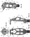
- FIGS. 3A-3D shown are various views of the chassis assembly 102 without an interchangeable module 104 installed.
- FIG. 3A shows a top view
- FIG. 3B shows a front view
- FIG. 3C shows a left side view
- FIG. 3D shows a perspective view of the chassis assembly 102.
- the grooves and/or tabs 218 align with one of the horizontal members 210. This can provide additional rigidity and strength for securing the interchangeable modules 104 in place.
- FIG. 3B illustrates the vertical central member 204 with two arms 222 that separate and extend to the attachment fixtures 208 to avoid interference with the joint portion 108.
- the shape of the arms 222 can be designed to handle the stress and strain placed on the structural frame during use.
- the module 104 includes a locking mechanism 306 that engages with the joint portion 108 to couple or engage the functionality of the module 104 with the chassis assembly 102.
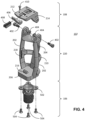
- FIG. 4 shows an exploded view of the chassis assembly 102 including the joint portion 108, the structural frame 220, and the mounting portion 106.
- the joint portion 108 can include the mounting plate 212 (or other attachment mechanism) with two pivot arms 214 extending from one end of the mounting plate 212.
- the pivot arms 214 are sized to fit between the attachment fixtures 208, and both include openings or holes that can be aligned with corresponding opening or holes in the attachment fixtures 208 to allow the joint portion 108 to pivotally attach to the attachment fixtures 208 of the structural frame 220.
- Fasteners such as, e.g., shoulder bolts 402 and barrel nuts 404 can extend through the openings. Spacers and/or sleeves can be used to ensure proper alignment of the joint portion 108, and can be used to reduce friction.
- the joint portion 108 also includes a lever 406 and locking wedge 408, which facilitate coupling of the locking mechanism 306 of the interchangeable module 104 to the mounting plate 212.
- the lever 406 can be pivotally attached to the mounting plate 212 using, e.g., a recessed screw 410, bolt or other appropriate fastener.
- the lever 406 acts as a camshaft that linearly displaces the locking wedge 408 into the locking mechanism 306 by rotating the lever 406 about the screw 410, the tab at the proximal end moves the locking wedge 408 forward to engage with the top flap or flanges of the locking mechanism 306, thereby securing the module 104 to the joint portion 108.
- the chassis assembly 102 includes the mounting portion 106, which can be detachably attached to the mounting base 206 of the structural frame 220 as illustrated in FIG. 4 .
- the mounting portion 106 can include a mounting adapter 502 that can be secured to the mounting base 206 via one or more screws (e.g., 4 flat head hex drive stainless screws) or other appropriate fasteners 504.
- the mounting portion 106 may also be attached using other appropriate mounting methods such as, e.g ., a sliding or rotating lock assembly. For example, a ball lock may be utilized.
- the mounting portion 106 can be developed by a prosthetist to fit the user.
- a lock and plate mechanism 506 can be fitted to provide a standardized fitting to attach virtually any foot and pylon systems (e.g ., footlankle system, sprinting blades, cycling clip foot mounts, inflexible mounts, or elastic keel feet designed for particular activities) available to the user.
- Other attachment mechanisms can be fitted to accommodate various foot configurations, e.g ., torque connectors, transcutaneous connectors, sliding locks, threaded pipes, button clips, and/or collar locks. Hand and/or other attachments may also be utilized for arm prosthetics.
- the interchangeable module 104 can take various forms (e.g ., damper driven, robotic, computer controlled, etc. ) .
- shock/piston, EVA (e.g. , rubber and/or polymer), microprocessor units (MPUs) or other components can be included in the interchangeable modules 104 to create a specialized unit or module to provide a specific result in applied applications.
- EVA e.g. , rubber and/or polymer
- MPUs microprocessor units
- the damper can be, e.g ., hydraulic, pneumatic, electromagnetic, spring, etc.
- the interchangeable module 104 can include a module casing 302, a locking mechanism 306, and a pivot point (or recess) 308 ( FIG. 6B ), which can be incorporated into the module casing 302.
- the locking mechanism 306 can include a top snap or flanges 310, which engage with the locking wedge 408 ( FIG. 4 ) affixed to the mounting plate 212.
- the top snap can be configured to secure the interchangeable module 104 into the chassis assembly 102. As shown in FIG.
- the top snap of the locking mechanism 306 includes opposing flanges 310 that are angled inward toward each other.
- the flanges 310 are flexibly connected to the end of the module casing 302 opposite the pivot point 308. The connection allows the flanges 310 to flex outward, away from each other to engage with the mounting plate 212.
- the interchangeable module 104 can be made from titanium, polymers, carbon fibers, aluminum, stainless steel, or combinations thereof.
- FIGS. 6A and 6B illustrate a cross-sectional view of the damper driven module 104.
- the module casing 302 can enclose the interior mechanisms, such as the damper assembly 312 in an internal void 314.
- the cross-section (A-A) is taken along the centerline of the module 104 from the front side to the rear side between the two flanges 310 of the locking mechanism 306.
- the cross-sectional view A-A is presented in FIG. 6B .
- the damper assembly 312 comprises a piston in a cylinder 316.
- Movement of the piston in the cylinder 316 is dampened by the fluid (e.g ., oil, water, air or other suitable hydraulic or pneumatic fluid) in the cylinder 316.
- the amount of damping provided by the damper assembly 312 can be affected by the viscosity of the fluid, size of the cylinder 316, size of the piston, clearance between the piston and cylinder wall, or other appropriate design variable.
- the damping assembly 312 is connected to the locking mechanism 306 by a piston rod 318 that passes through an opening 320 in the module casing 302.
- the connection between the piston rod 318 and locking mechanism 306 is configured to rotate ( e.g. , about a connecting pin). As shown in the enlarged view of FIG.
- the top snap is connected to the module casing 302 at one end, while the other end is coupled to the piston rod 318 to a surface of the top snap opposite the flanges 310.
- tabs can extend on both sides of the piston rod 318 with a connection pin extending through both the tabs and the piston rod.
- the opposite end of the cylinder 316 is also configured to rotate about a connection pin or shaft, which can extend across the module casing 302 through the internal void 314. This rotation can maintain alignment of the piston rod 318 in the damper assembly 312 as the top snap moves about the connection to the module casing 302.
- FIGS. 7A and 7B illustrate another cross-sectional view of the damper driven module 104.
- the cross-section (F-F) is perpendicular to cross-section A-A of FIG. 6A and extends across the module 104 from the left side to the right side and passes through the flanges 310.
- the cross-sectional view F-F is presented in FIG. 7B , which shows the internal void 314 of the module casing 302 and a portion of the cylinder 316 of the damper assembly 312.
- Detail AC illustrates the relationship of the top snap or flanges 310 of the locking mechanism 306 and detail C shows the positioning of the top snap or flanges 310 on the module casing 302.
- narrow sections are provided at the lower corners of the flanges 310 to allow for flexing and outward movement.
- Detail C shows a side view of the flexible connection with the module case 302. Magnetic ball, snap fit, or likewise can be used.
- FIGS. 8A-13C illustrate an example of the process of installing the interchangeable module 104 into the chassis assembly 102.
- the modular prosthetic 100 has been illustrated with the joint portion 108 in a standing position where the prosthetic would be load bearing with the mounting plate 212 substantially perpendicular to a longitudinal axis of the chassis assembly 102.
- FIGS. 8A-8C To insert an interchangeable module 104, the user assumes a non-load bearing position (e.g ., sitting), and loosens the lever 406 ( e.g ., rotating it outward) on the joint portion 108 of the chassis assembly 102, allowing the joint portion 108 to pivot into an open position as illustrated in FIGS. 8A-8C .
- the mounting plate 212 can be positioned substantially parallel with the longitudinal axis of the chassis assembly 102 as shown in FIGS. 8A-8C.
- FIG. 8A is a front view of the interchangeable module 104 being aligned with the anchor 216 of the chassis assembly 102.
- the lever 406 is shown rotated outward thereby allowing the locking wedge 408 to move to a retracted position.
- the cross-section G-G passing along the longitudinal axis, from front to rear, is shown In FIG. 8B .
- the interchangeable module 104 can be inserted at an angle into the chassis assembly 102 with the anchor 216 on the mounting base 206 aligned with the pivot point (or recess) 308 on the bottom of the module casing 302 as shown in FIG. 8B .
- This alignment between the anchor 216 and recess 308 is enlarged in detail AD.
- the corner of the module casing 302 can rest on the surface of the mounting base 206 as shown in FIG. 8C while positioning the pivot point 308 on the anchor 216.
- the module 104 can then be rotated about the pivot point 308 and anchor 216 into the structural frame 220.
- the mounting ridges (or tabs) 304 on the sides of the module 104 contact the mounting grooves (or slots) 218 in the vertical side members 202 of the structural frame as illustrated in FIGS. 9A-9C .
- Detail F is an enlarged view illustrating the engagement of the mounting ridges (or tabs) 304 with the mounting grooves (or slots) 218.
- the cross-section D-D passing through one of the vertical side members 202 of the structural frame 220 is shown in FIG.
- the mounting ridge (or tab) 304 is in contact with the vertical side member 202 prior to insertion into the mounting groove (or slot) 304. This is enlarged in detail E of FIG. 9B .
- the mounting ridges (or tabs) 304 can be inserted into the corresponding mounting grooves (or slots) 218.
- the vertical side members 202 of the structural frame can include mounting ridges (or tabs) and the module casing 302 can include mounting grooves (or slots) to provide the engagement.
- FIGS. 10A-10C A snap fit can be achieved upon insertion of the interchangeable module 104 into the chassis assembly 102, providing an easy but secure assembly, as shown in FIGS. 10A-10C .
- the cross-section G-G of FIG. 10A passes through the same vertical side member 202 as in FIG. 9B .
- the mounting ridge (or tab) 304 is snapped into the mounting groove (or slot) 304.
- FIG. 10C shows the interchangeable module 104 secured in the structural frame 220 by the mounting ridges 304 in the mounting grooves 218.
- Application of force on the rear of the module 104, through the structural frame 220, can unsnap the interchangeable module 104 from the chassis assembly 102.
- FIGS. 10D, 10E and 10F show front, side and perspective views of the chassis assembly 102 with the interchangeable module 104 snapped in position and the mounting portion 106 attached to the mounting base 206.
- FIGS. 11A and 11B With the interchangeable module 104 snapped into position, the user can stand up (or extend the leg) pivoting the joint portion 108 forward as illustrated in FIGS. 11A and 11B .
- the mounting plate 212 In this position, the mounting plate 212 is in a load bearing position substantially perpendicular to the longitudinal axis of the chassis assembly 102. This motion will position the top snap of the locking mechanism 306 in line with the locking wedge 408 of the joint portion 108, as shown in the example in FIGS. 11A-11C .
- the cross-sectional view K-K of FIG. 11A is presented in FIG. 11B , which shows the internal void 314 of the module casing 302 and a portion of the cylinder 316 of the damper assembly 312.
- FIG. 11C shows the cross-section S-S of FIG. 11A , with detail T providing an enlarged vertical view of the locking wedge 408 aligned with the top snap or flanges 310 of the locking mechanism 306.
- the top snap or flanges 310 are located within an open cavity 322 of the mounting plate 212.
- the lever 406 extending outward as shown in FIGS. 11A and 11C , the distal end of the locking wedge 408 is adjacent to one end of the gap between the flanges 310.
- the inward tilt of the flanges 310 allow the top snap to easily align with the cavity 322 in the mounting plate 212.
- the pre-bent snap fit allows for a relatively minimal insertion and removal force.
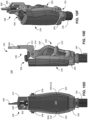
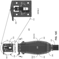
- FIGS. 12A-12C the lever 406 can be rotated flush with the front of the mounting plate 212.
- the lever 406 is rotated about 90 degrees, the short tab presses against the end of the locking wedge 408.
- the lever action of this motion linearly displaces the locking wedge 408 into the top snap of the locking mechanism 306, spreading the flanges 310 of the top snap as the locking wedge 408 is forced between them.
- FIG. 12B shows the cross-sectional view M-M
- FIG. 12C shows the cross-sectional view N-N indicated in FIG. 12A .
- the top snap or flanges 310 are forced apart and engage with the outer surface of the cavity 322. With the locking wedge 408 inserted between the ends of the flanges 301, the flanges 301 can provide a friction fit with the sides of the open cavity 322 thereby locking the mounting plate 212 to the module 104.
- the joint portion 108 locks in the XYZ coordinates, as shown in FIG. 12C .
- the cross-section Y-Y, and the enlarged detail Z illustrates the positioning of the top snap or flanges 310 of the locking mechanism 306 with the lever 406 in the locked position with the locking wedge 408 secured between the flanges 310.
- the lever 406 can be rotated outward allowing the locking wedge 408 to retract from between the flanges 310.
- the joint portion 108 can then be pivoted into an open position as illustrated in FIGS. 10A-10D , and the interchangeable module 104 removed from the structural frame 220 as previously discussed. Another module 104 can then be inserted and secured into position.
Landscapes
- Health & Medical Sciences (AREA)
- Transplantation (AREA)
- Heart & Thoracic Surgery (AREA)
- Oral & Maxillofacial Surgery (AREA)
- Engineering & Computer Science (AREA)
- Biomedical Technology (AREA)
- Cardiology (AREA)
- Vascular Medicine (AREA)
- Life Sciences & Earth Sciences (AREA)
- Animal Behavior & Ethology (AREA)
- General Health & Medical Sciences (AREA)
- Public Health (AREA)
- Veterinary Medicine (AREA)
- Orthopedic Medicine & Surgery (AREA)
- Prostheses (AREA)
Claims (18)
- Dispositif prothétique modulaire, comprenant :un ensemble châssis (102) comprenant une partie articulation (108), un cadre structurel (220) et une partie montage (106) ; etun module (104) interchangeable conçu pour être attaché de manière amovible à l'ensemble châssis, dans lequel le module interchangeable est fixé à la partie articulation par l'intermédiaire d'un mécanisme de verrouillage (406, 408) du module interchangeable, dans lequel le mécanisme de verrouillage vient en prise avec la partie articulation, caractérisé en ce que le mécanisme de verrouillage vient en prise avec l'articulation par l'intermédiaire d'un levier (406) et d'une cale de verrouillage (408).
- Dispositif selon la revendication 1, dans lequel l'ensemble châssis est fixé à un utilisateur par attachement de l'ensemble châssis à un implant osseux existant ou à une emboîture prothétique existante.
- Dispositif selon la revendication 1, dans lequel la partie articulation est fixée au niveau d'une extrémité proximale à l'ensemble châssis et la partie montage est fixée à une extrémité distale de l'ensemble châssis.
- Dispositif selon la revendication 1, dans lequel le cadre structurel reçoit le module interchangeable, le module interchangeable étant fixé à l'ensemble châssis par l'intermédiaire de fentes d'accouplement (218) et de languettes (304) complémentaires au niveau du cadre structurel et du module interchangeable.
- Dispositif selon la revendication 1, dans lequel le mécanisme de verrouillage comprend un bouton-pression (310) supérieur conçu pour venir en prise avec la cale de verrouillage pour fixer la partie articulation au module interchangeable.
- Dispositif selon la revendication 5, dans lequel le bouton-pression supérieur est accouplé à un mécanisme d'amortissement (312) du module interchangeable.
- Dispositif selon la revendication 6, dans lequel le mécanisme d'amortissement est un ensemble piston.
- Dispositif selon la revendication 1, dans lequel l'ensemble châssis est conçu pour recevoir des modules prothétiques amovibles attachés à la partie montage.
- Dispositif selon l'une quelconque des revendications 1 à 8, dans lequel le module interchangeable comprend un mécanisme (312) entraîné par un amortisseur.
- Dispositif selon l'une quelconque des revendications 1 à 9, dans lequel le dispositif prothétique modulaire est choisi parmi une jambe, une partie inférieure de jambe, un bras et un avant-bras.
- Dispositif selon l'une quelconque des revendications 1 à 10, dans lequel la partie articulation est solidement attachée à un implant osseux existant ou à une emboîture prothétique existante.
- Dispositif selon l'une quelconque des revendications 1 et 2, dans lequel :la partie articulation comprend une plaque de montage (212) rotative conçue pour être fixée à un implant ou à une emboîture prothétique d'un utilisateur ; etle mécanisme de verrouillage est conçu pour venir en prise avec une cavité (322) ouverte de la plaque de montage rotative à partir d'un côté opposé à l'implant ou à l'emboîture prothétique pour le ou la fixer dans une position de port de charge.
- Dispositif selon la revendication 12, dans lequel le mécanisme de verrouillage comprend une paire de brides conçues pour venir en prise avec une surface de la cavité ouverte pour fixer la plaque de montage rotative dans la position de port de charge.
- Dispositif selon la revendication 13, dans lequel la paire de brides s'incline vers l'intérieur, l'une vers l'autre, pour faciliter l'insertion dans la cavité ouverte, et fléchit vers l'extérieur pour venir en prise avec la surface de la cavité ouverte.
- Dispositif selon la revendication 14, dans lequel la plaque de montage rotative comprend la cale de verrouillage, laquelle contraint la paire de brides à fléchir vers l'extérieur lorsqu'elle est insérée entre la paire de brides.
- Dispositif selon la revendication 15, dans lequel la plaque de montage rotative comprend le levier, lequel contraint la cale de verrouillage entre la paire de brides en cas de rotation, d'une position étendue à une position verrouillée.
- Dispositif selon l'une quelconque des revendications 12 à 16, dans lequel l'ensemble châssis comprend une ancre (216) sur une surface de montage de module au niveau d'une extrémité distale de l'ensemble châssis, et le module interchangeable comprend un évidement correspondant, conçu pour s'aligner avec l'ancre lorsque le module interchangeable est inséré dans l'ensemble châssis.
- Dispositif selon la revendication 17, dans lequel le module interchangeable et le cadre structurel de l'ensemble châssis comprennent des arêtes de montage et des rainures de montage conçues pour fixer le module interchangeable dans le cadre structurel.
Priority Applications (1)
| Application Number | Priority Date | Filing Date | Title |
|---|---|---|---|
| EP24200465.3A EP4454618A3 (fr) | 2017-09-01 | 2018-08-31 | Dispositifs prothétiques modulaires |
Applications Claiming Priority (2)
| Application Number | Priority Date | Filing Date | Title |
|---|---|---|---|
| US201762553586P | 2017-09-01 | 2017-09-01 | |
| PCT/US2018/049085 WO2019046715A1 (fr) | 2017-09-01 | 2018-08-31 | Dispositifs prothétiques modulaires |
Related Child Applications (2)
| Application Number | Title | Priority Date | Filing Date |
|---|---|---|---|
| EP24200465.3A Division EP4454618A3 (fr) | 2017-09-01 | 2018-08-31 | Dispositifs prothétiques modulaires |
| EP24200465.3A Division-Into EP4454618A3 (fr) | 2017-09-01 | 2018-08-31 | Dispositifs prothétiques modulaires |
Publications (4)
| Publication Number | Publication Date |
|---|---|
| EP3675778A1 EP3675778A1 (fr) | 2020-07-08 |
| EP3675778A4 EP3675778A4 (fr) | 2021-06-23 |
| EP3675778C0 EP3675778C0 (fr) | 2024-10-23 |
| EP3675778B1 true EP3675778B1 (fr) | 2024-10-23 |
Family
ID=65526074
Family Applications (2)
| Application Number | Title | Priority Date | Filing Date |
|---|---|---|---|
| EP18850320.5A Active EP3675778B1 (fr) | 2017-09-01 | 2018-08-31 | Dispositifs prothétiques modulaires |
| EP24200465.3A Pending EP4454618A3 (fr) | 2017-09-01 | 2018-08-31 | Dispositifs prothétiques modulaires |
Family Applications After (1)
| Application Number | Title | Priority Date | Filing Date |
|---|---|---|---|
| EP24200465.3A Pending EP4454618A3 (fr) | 2017-09-01 | 2018-08-31 | Dispositifs prothétiques modulaires |
Country Status (3)
| Country | Link |
|---|---|
| US (2) | US11337833B2 (fr) |
| EP (2) | EP3675778B1 (fr) |
| WO (1) | WO2019046715A1 (fr) |
Families Citing this family (1)
| Publication number | Priority date | Publication date | Assignee | Title |
|---|---|---|---|---|
| EP3675778B1 (fr) * | 2017-09-01 | 2024-10-23 | University of Florida Research Foundation | Dispositifs prothétiques modulaires |
Family Cites Families (12)
| Publication number | Priority date | Publication date | Assignee | Title |
|---|---|---|---|---|
| US2568053A (en) | 1948-10-07 | 1951-09-18 | John G Catranis | Knee lock mechanism for artificial legs |
| GB2098072B (en) | 1980-09-25 | 1984-03-21 | Blatchford & Sons Chas A Ltd | Improved endo-skeletal artificial limb |
| US4564365A (en) | 1983-03-18 | 1986-01-14 | Winer Richard A | Quick change mechanism for a limb prosthesis |
| GB9105464D0 (en) * | 1991-03-14 | 1991-05-01 | Blatchford & Sons Ltd | An artificial leg |
| US7410503B2 (en) * | 2001-03-30 | 2008-08-12 | Bioquest Prosthetics Llc | Prosthetic foot with tunable performance |
| CA2495110C (fr) * | 2002-08-10 | 2008-11-18 | H. Simon William | Procede et appareil de reparation de la region du mi-pied par le biais d'un clou centromedullaire |
| US7044983B1 (en) | 2003-07-24 | 2006-05-16 | Chia Pao Cheng | Positioning and buffering device for artificial knee joint |
| WO2007002734A1 (fr) * | 2005-06-27 | 2007-01-04 | Frye Todd Jarem Jr | Prothese de genou et ensemble de jambe a utiliser dans des activites d'athletisme dans lesquelles les quadriceps interviennent generalement pour realiser la fonction de support et la fonction dynamique |
| US8414658B2 (en) | 2008-10-01 | 2013-04-09 | Invisible Hand Enterprises, Llc | Anatomically-configured adjustable upper extremity prosthetic device |
| DE102014000647B4 (de) * | 2014-01-17 | 2015-09-24 | Otto Bock Healthcare Products Gmbh | Knöchelmanschette |
| US11096786B2 (en) * | 2015-02-04 | 2021-08-24 | Acumed Llc | Elbow arthroplasty apparatus, system, and method |
| EP3675778B1 (fr) * | 2017-09-01 | 2024-10-23 | University of Florida Research Foundation | Dispositifs prothétiques modulaires |
-
2018
- 2018-08-31 EP EP18850320.5A patent/EP3675778B1/fr active Active
- 2018-08-31 EP EP24200465.3A patent/EP4454618A3/fr active Pending
- 2018-08-31 US US16/643,372 patent/US11337833B2/en active Active
- 2018-08-31 WO PCT/US2018/049085 patent/WO2019046715A1/fr not_active Ceased
-
2022
- 2022-05-16 US US17/745,382 patent/US11998461B2/en active Active
Also Published As
| Publication number | Publication date |
|---|---|
| WO2019046715A1 (fr) | 2019-03-07 |
| EP3675778A1 (fr) | 2020-07-08 |
| EP3675778C0 (fr) | 2024-10-23 |
| EP4454618A3 (fr) | 2024-12-25 |
| US20210059842A1 (en) | 2021-03-04 |
| EP4454618A2 (fr) | 2024-10-30 |
| US11337833B2 (en) | 2022-05-24 |
| US20220346984A1 (en) | 2022-11-03 |
| EP3675778A4 (fr) | 2021-06-23 |
| US11998461B2 (en) | 2024-06-04 |
Similar Documents
| Publication | Publication Date | Title |
|---|---|---|
| US11622877B2 (en) | Dynamic range of motion orthosis | |
| EP2063818B1 (fr) | Palier sans couple pour dispositifs orthotiques et prothétiques | |
| US10589435B2 (en) | Shoulder module for an exoskeleton structure | |
| CN106426097B (zh) | 一种下肢外骨骼助力机构 | |
| US10639784B2 (en) | Exoskeleton structure that provides force assistance to the user | |
| US6013105A (en) | Prosthesis connector and alignment assembly | |
| JP2019505398A (ja) | 外骨格構造用のバックモジュール | |
| EP3107503B1 (fr) | Prothèse de genou | |
| US20220346984A1 (en) | Modular prosthetics devices | |
| KR102637141B1 (ko) | 보조기, 보조기 조절 시스템 및 조절 방법 | |
| US9901467B2 (en) | Above-knee prosthesis | |
| KR101455330B1 (ko) | 인체 관절 활동 보조기구 | |
| Sancho-Pérez et al. | Mechanical description of ATLAS 2020, a 10-DOF paediatric exoskeleton | |
| US10857008B2 (en) | Adapter for self-alignment in 3 dimensional planes for passive prosthetics | |
| WO2011123119A1 (fr) | Prothèse de genou | |
| US10405997B2 (en) | Passive artificial knee | |
| CN113442117B (zh) | 一种负重助力外骨骼 | |
| EP0413450B1 (fr) | Elément d'un membre artificiel | |
| US20160089243A1 (en) | Injection mouldable polymeric composite based passive polycentric knee joint | |
| US9782273B2 (en) | Flexible coupling system | |
| US20050240284A1 (en) | Prosthetic foot devices | |
| CN120112253A (zh) | 用于假足结构的踝式系统 | |
| BR202022013164U2 (pt) | Fixação articulada para prótese de membro superior voltada para ciclismo | |
| WO2025155793A1 (fr) | Prothèse de genou | |
| KR101262649B1 (ko) | 족 관절 재활장치 |
Legal Events
| Date | Code | Title | Description |
|---|---|---|---|
| STAA | Information on the status of an ep patent application or granted ep patent |
Free format text: STATUS: THE INTERNATIONAL PUBLICATION HAS BEEN MADE |
|
| PUAI | Public reference made under article 153(3) epc to a published international application that has entered the european phase |
Free format text: ORIGINAL CODE: 0009012 |
|
| STAA | Information on the status of an ep patent application or granted ep patent |
Free format text: STATUS: REQUEST FOR EXAMINATION WAS MADE |
|
| 17P | Request for examination filed |
Effective date: 20200221 |
|
| AK | Designated contracting states |
Kind code of ref document: A1 Designated state(s): AL AT BE BG CH CY CZ DE DK EE ES FI FR GB GR HR HU IE IS IT LI LT LU LV MC MK MT NL NO PL PT RO RS SE SI SK SM TR |
|
| AX | Request for extension of the european patent |
Extension state: BA ME |
|
| DAV | Request for validation of the european patent (deleted) | ||
| DAX | Request for extension of the european patent (deleted) | ||
| RIN1 | Information on inventor provided before grant (corrected) |
Inventor name: SAWYER, WALLACE GREGORY Inventor name: BARTLETT, BRIAN P. Inventor name: HOOD, DEREK L. |
|
| RIC1 | Information provided on ipc code assigned before grant |
Ipc: A61F 2/60 20060101AFI20210429BHEP Ipc: A61F 2/54 20060101ALI20210429BHEP Ipc: A61F 2/76 20060101ALI20210429BHEP Ipc: A61F 2/50 20060101ALI20210429BHEP Ipc: A61F 2/58 20060101ALI20210429BHEP Ipc: A61F 2/64 20060101ALI20210429BHEP |
|
| RIC1 | Information provided on ipc code assigned before grant |
Ipc: A61F 2/60 20060101AFI20210503BHEP Ipc: A61F 2/54 20060101ALI20210503BHEP Ipc: A61F 2/76 20060101ALI20210503BHEP Ipc: A61F 2/50 20060101ALI20210503BHEP Ipc: A61F 2/58 20060101ALI20210503BHEP Ipc: A61F 2/64 20060101ALI20210503BHEP |
|
| RIC1 | Information provided on ipc code assigned before grant |
Ipc: A61F 2/60 20060101AFI20210512BHEP Ipc: A61F 2/54 20060101ALI20210512BHEP Ipc: A61F 2/76 20060101ALI20210512BHEP Ipc: A61F 2/50 20060101ALI20210512BHEP Ipc: A61F 2/58 20060101ALI20210512BHEP Ipc: A61F 2/64 20060101ALI20210512BHEP |
|
| A4 | Supplementary search report drawn up and despatched |
Effective date: 20210526 |
|
| GRAP | Despatch of communication of intention to grant a patent |
Free format text: ORIGINAL CODE: EPIDOSNIGR1 |
|
| STAA | Information on the status of an ep patent application or granted ep patent |
Free format text: STATUS: GRANT OF PATENT IS INTENDED |
|
| INTG | Intention to grant announced |
Effective date: 20240522 |
|
| GRAS | Grant fee paid |
Free format text: ORIGINAL CODE: EPIDOSNIGR3 |
|
| GRAA | (expected) grant |
Free format text: ORIGINAL CODE: 0009210 |
|
| STAA | Information on the status of an ep patent application or granted ep patent |
Free format text: STATUS: THE PATENT HAS BEEN GRANTED |
|
| AK | Designated contracting states |
Kind code of ref document: B1 Designated state(s): AL AT BE BG CH CY CZ DE DK EE ES FI FR GB GR HR HU IE IS IT LI LT LU LV MC MK MT NL NO PL PT RO RS SE SI SK SM TR |
|
| REG | Reference to a national code |
Ref country code: GB Ref legal event code: FG4D |
|
| REG | Reference to a national code |
Ref country code: CH Ref legal event code: EP |
|
| REG | Reference to a national code |
Ref country code: DE Ref legal event code: R096 Ref document number: 602018075821 Country of ref document: DE |
|
| REG | Reference to a national code |
Ref country code: IE Ref legal event code: FG4D |
|
| U01 | Request for unitary effect filed |
Effective date: 20241023 |
|
| U07 | Unitary effect registered |
Designated state(s): AT BE BG DE DK EE FI FR IT LT LU LV MT NL PT RO SE SI Effective date: 20241030 |
|
| PG25 | Lapsed in a contracting state [announced via postgrant information from national office to epo] |
Ref country code: HR Free format text: LAPSE BECAUSE OF FAILURE TO SUBMIT A TRANSLATION OF THE DESCRIPTION OR TO PAY THE FEE WITHIN THE PRESCRIBED TIME-LIMIT Effective date: 20241023 Ref country code: IS Free format text: LAPSE BECAUSE OF FAILURE TO SUBMIT A TRANSLATION OF THE DESCRIPTION OR TO PAY THE FEE WITHIN THE PRESCRIBED TIME-LIMIT Effective date: 20250223 |
|
| PG25 | Lapsed in a contracting state [announced via postgrant information from national office to epo] |
Ref country code: ES Free format text: LAPSE BECAUSE OF FAILURE TO SUBMIT A TRANSLATION OF THE DESCRIPTION OR TO PAY THE FEE WITHIN THE PRESCRIBED TIME-LIMIT Effective date: 20241023 |
|
| PG25 | Lapsed in a contracting state [announced via postgrant information from national office to epo] |
Ref country code: NO Free format text: LAPSE BECAUSE OF FAILURE TO SUBMIT A TRANSLATION OF THE DESCRIPTION OR TO PAY THE FEE WITHIN THE PRESCRIBED TIME-LIMIT Effective date: 20250123 |
|
| PG25 | Lapsed in a contracting state [announced via postgrant information from national office to epo] |
Ref country code: GR Free format text: LAPSE BECAUSE OF FAILURE TO SUBMIT A TRANSLATION OF THE DESCRIPTION OR TO PAY THE FEE WITHIN THE PRESCRIBED TIME-LIMIT Effective date: 20250124 |
|
| PG25 | Lapsed in a contracting state [announced via postgrant information from national office to epo] |
Ref country code: PL Free format text: LAPSE BECAUSE OF FAILURE TO SUBMIT A TRANSLATION OF THE DESCRIPTION OR TO PAY THE FEE WITHIN THE PRESCRIBED TIME-LIMIT Effective date: 20241023 |
|
| PG25 | Lapsed in a contracting state [announced via postgrant information from national office to epo] |
Ref country code: RS Free format text: LAPSE BECAUSE OF FAILURE TO SUBMIT A TRANSLATION OF THE DESCRIPTION OR TO PAY THE FEE WITHIN THE PRESCRIBED TIME-LIMIT Effective date: 20250123 |
|
| PG25 | Lapsed in a contracting state [announced via postgrant information from national office to epo] |
Ref country code: SM Free format text: LAPSE BECAUSE OF FAILURE TO SUBMIT A TRANSLATION OF THE DESCRIPTION OR TO PAY THE FEE WITHIN THE PRESCRIBED TIME-LIMIT Effective date: 20241023 |
|
| PG25 | Lapsed in a contracting state [announced via postgrant information from national office to epo] |
Ref country code: SK Free format text: LAPSE BECAUSE OF FAILURE TO SUBMIT A TRANSLATION OF THE DESCRIPTION OR TO PAY THE FEE WITHIN THE PRESCRIBED TIME-LIMIT Effective date: 20241023 |
|
| PG25 | Lapsed in a contracting state [announced via postgrant information from national office to epo] |
Ref country code: CZ Free format text: LAPSE BECAUSE OF FAILURE TO SUBMIT A TRANSLATION OF THE DESCRIPTION OR TO PAY THE FEE WITHIN THE PRESCRIBED TIME-LIMIT Effective date: 20241023 |
|
| PLBE | No opposition filed within time limit |
Free format text: ORIGINAL CODE: 0009261 |
|
| STAA | Information on the status of an ep patent application or granted ep patent |
Free format text: STATUS: NO OPPOSITION FILED WITHIN TIME LIMIT |
|
| 26N | No opposition filed |
Effective date: 20250724 |
|
| U20 | Renewal fee for the european patent with unitary effect paid |
Year of fee payment: 8 Effective date: 20250827 |
|
| PGFP | Annual fee paid to national office [announced via postgrant information from national office to epo] |
Ref country code: GB Payment date: 20250827 Year of fee payment: 8 |
|
| REG | Reference to a national code |
Ref country code: CH Ref legal event code: H13 Free format text: ST27 STATUS EVENT CODE: U-0-0-H10-H13 (AS PROVIDED BY THE NATIONAL OFFICE) Effective date: 20260324 |
|
| PG25 | Lapsed in a contracting state [announced via postgrant information from national office to epo] |
Ref country code: MC Free format text: LAPSE BECAUSE OF FAILURE TO SUBMIT A TRANSLATION OF THE DESCRIPTION OR TO PAY THE FEE WITHIN THE PRESCRIBED TIME-LIMIT Effective date: 20241023 |
|
| PG25 | Lapsed in a contracting state [announced via postgrant information from national office to epo] |
Ref country code: CH Free format text: LAPSE BECAUSE OF NON-PAYMENT OF DUE FEES Effective date: 20250831 |