EP3675959B1 - Ensemble transducteur pour générer des ultrasons focalisés - Google Patents
Ensemble transducteur pour générer des ultrasons focalisés Download PDFInfo
- Publication number
- EP3675959B1 EP3675959B1 EP18849828.1A EP18849828A EP3675959B1 EP 3675959 B1 EP3675959 B1 EP 3675959B1 EP 18849828 A EP18849828 A EP 18849828A EP 3675959 B1 EP3675959 B1 EP 3675959B1
- Authority
- EP
- European Patent Office
- Prior art keywords
- acoustic
- ultrasound
- lens
- layer
- intermediate layer
- Prior art date
- Legal status (The legal status is an assumption and is not a legal conclusion. Google has not performed a legal analysis and makes no representation as to the accuracy of the status listed.)
- Active
Links
Images








Classifications
-
- B—PERFORMING OPERATIONS; TRANSPORTING
- B06—GENERATING OR TRANSMITTING MECHANICAL VIBRATIONS IN GENERAL
- B06B—METHODS OR APPARATUS FOR GENERATING OR TRANSMITTING MECHANICAL VIBRATIONS OF INFRASONIC, SONIC, OR ULTRASONIC FREQUENCY, e.g. FOR PERFORMING MECHANICAL WORK IN GENERAL
- B06B1/00—Methods or apparatus for generating mechanical vibrations of infrasonic, sonic, or ultrasonic frequency
- B06B1/02—Methods or apparatus for generating mechanical vibrations of infrasonic, sonic, or ultrasonic frequency making use of electrical energy
- B06B1/06—Methods or apparatus for generating mechanical vibrations of infrasonic, sonic, or ultrasonic frequency making use of electrical energy operating with piezoelectric effect or with electrostriction
- B06B1/0644—Methods or apparatus for generating mechanical vibrations of infrasonic, sonic, or ultrasonic frequency making use of electrical energy operating with piezoelectric effect or with electrostriction using a single piezoelectric element
- B06B1/0662—Methods or apparatus for generating mechanical vibrations of infrasonic, sonic, or ultrasonic frequency making use of electrical energy operating with piezoelectric effect or with electrostriction using a single piezoelectric element with an electrode on the sensitive surface
- B06B1/067—Methods or apparatus for generating mechanical vibrations of infrasonic, sonic, or ultrasonic frequency making use of electrical energy operating with piezoelectric effect or with electrostriction using a single piezoelectric element with an electrode on the sensitive surface which is used as, or combined with, an impedance matching layer
-
- A—HUMAN NECESSITIES
- A61—MEDICAL OR VETERINARY SCIENCE; HYGIENE
- A61N—ELECTROTHERAPY; MAGNETOTHERAPY; RADIATION THERAPY; ULTRASOUND THERAPY
- A61N7/00—Ultrasound therapy
-
- A—HUMAN NECESSITIES
- A61—MEDICAL OR VETERINARY SCIENCE; HYGIENE
- A61N—ELECTROTHERAPY; MAGNETOTHERAPY; RADIATION THERAPY; ULTRASOUND THERAPY
- A61N7/00—Ultrasound therapy
- A61N7/02—Localised ultrasound hyperthermia
-
- A—HUMAN NECESSITIES
- A61—MEDICAL OR VETERINARY SCIENCE; HYGIENE
- A61B—DIAGNOSIS; SURGERY; IDENTIFICATION
- A61B17/00—Surgical instruments, devices or methods
- A61B17/22—Implements for squeezing-off ulcers or the like on inner organs of the body; Implements for scraping-out cavities of body organs, e.g. bones; for invasive removal or destruction of calculus using mechanical vibrations; for removing obstructions in blood vessels, not otherwise provided for
- A61B17/225—Implements for squeezing-off ulcers or the like on inner organs of the body; Implements for scraping-out cavities of body organs, e.g. bones; for invasive removal or destruction of calculus using mechanical vibrations; for removing obstructions in blood vessels, not otherwise provided for for extracorporeal shock wave lithotripsy [ESWL], e.g. by using ultrasonic waves
-
- A—HUMAN NECESSITIES
- A61—MEDICAL OR VETERINARY SCIENCE; HYGIENE
- A61N—ELECTROTHERAPY; MAGNETOTHERAPY; RADIATION THERAPY; ULTRASOUND THERAPY
- A61N7/00—Ultrasound therapy
- A61N2007/0004—Applications of ultrasound therapy
- A61N2007/0021—Neural system treatment
- A61N2007/003—Destruction of nerve tissue
-
- A—HUMAN NECESSITIES
- A61—MEDICAL OR VETERINARY SCIENCE; HYGIENE
- A61N—ELECTROTHERAPY; MAGNETOTHERAPY; RADIATION THERAPY; ULTRASOUND THERAPY
- A61N7/00—Ultrasound therapy
- A61N2007/0039—Ultrasound therapy using microbubbles
-
- A—HUMAN NECESSITIES
- A61—MEDICAL OR VETERINARY SCIENCE; HYGIENE
- A61N—ELECTROTHERAPY; MAGNETOTHERAPY; RADIATION THERAPY; ULTRASOUND THERAPY
- A61N7/00—Ultrasound therapy
- A61N2007/0056—Beam shaping elements
- A61N2007/006—Lenses
-
- A—HUMAN NECESSITIES
- A61—MEDICAL OR VETERINARY SCIENCE; HYGIENE
- A61N—ELECTROTHERAPY; MAGNETOTHERAPY; RADIATION THERAPY; ULTRASOUND THERAPY
- A61N7/00—Ultrasound therapy
- A61N2007/0056—Beam shaping elements
- A61N2007/0065—Concave transducers
-
- A—HUMAN NECESSITIES
- A61—MEDICAL OR VETERINARY SCIENCE; HYGIENE
- A61N—ELECTROTHERAPY; MAGNETOTHERAPY; RADIATION THERAPY; ULTRASOUND THERAPY
- A61N7/00—Ultrasound therapy
- A61N2007/0082—Scanning transducers
Definitions
- the present disclosure relates to focused ultrasound.
- the present disclosure relates to focused ultrasound for therapeutic applications, such as histotripsy and high intensity focused ultrasound (HIFU).
- HIFU high intensity focused ultrasound
- Histotripsy is a tissue ablation process in which short bursts of high intensity ultrasound are focused to a small focal region, exceeding the vapor pressure within the focal region and causing gas bubbles to form. When these bubbles collapse, the shockwave destroys the tissue structure, leaving liquified remnants of the original tissue at the focal region.
- HIFU High-intensity focused ultrasound
- heat can also damage the surrounding tissue.
- Both HIFU and histotripsy transducers function similarly, as both require the focusing of ultrasound to a small focal region.
- US Patent Publication No. US20080195003 discloses a focused ultrasound transducer includes a first ultrasonic emitter and at least one metallic ultrasonic lens acoustically coupled thereto.
- the emitter generates ultrasonic energy that propagates along a beam path projecting therefrom.
- the at least one metallic ultrasonic lens is positioned at least partially in the beam path so that it can direct (e.g., focus, defocus, and/or collimate) in at least one direction (or along at least one plane) at least some of the ultrasonic energy propagating from the emitter.
- the metallic lens may be formed by extrusion, by molding (e.g., diecast molding or thermoforming), or by sintering (e.g., powder metallurgy).
- the metallic lens also advantageously functions as a heat sink, improving thermal performance of the ultrasound transducer.
- US Patent Publication No. US20070055182 discloses a system and method for removing unwanted heat generated by a piezoelectric element of an ultrasound transducer.
- Some implementations have high thermal conductivity (HTC) material placed adjacent to the piezoelectric element.
- the HTC material can be thermally coupled to one or more heat sinks.
- Use of HTC material in conjunction with these piezoelectric element surfaces is managed to avoid degradation of propagating acoustic energy.
- Use of the HTC material in conjunction with heat sinks allows for creation of thermal paths away from the piezoelectric element. Active cooling of the heat sinks with water or air can further draw heat from the piezoelectric element.
- Further implementations form a composite matrix of thermally conductive material or interleave thermally conductive layers with piezoelectric material.
- the piezoelectric layer is a composite piezoelectric material having an acoustic impedance configured to match the acoustic impedance of the acoustic lens.
- the acoustic lens may be formed from aluminum, or an alloy thereof, and may have a distal surface having a non-spherical profile for producing a focal region that is smaller than an equivalent spherical lens.
- the acoustic lens may have an f-number less than two.
- the acoustic lens is coated with a polymer acoustic impedance matching layer that is compatible with deposition via chemical vapor deposition, such as a p-xylylene based polymer.
- a polymer acoustic impedance matching layer that is compatible with deposition via chemical vapor deposition, such as a p-xylylene based polymer.
- the acoustic lens is formed from aluminum or an alloy thereof, and the polymer acoustic impedance matching layer is a Parylene layer.
- the terms “comprises” and “comprising” are to be construed as being inclusive and open ended, and not exclusive. Specifically, when used in the specification and claims, the terms “comprises” and “comprising” and variations thereof mean the specified features, steps or components are included. These terms are not to be interpreted to exclude the presence of other features, steps or components.
- exemplary means “serving as an example, instance, or illustration,” and should not be construed as preferred or advantageous over other configurations disclosed herein.
- the terms “about” and “approximately” are meant to cover variations that may exist in the upper and lower limits of the ranges of values, such as variations in properties, parameters, and dimensions. Unless otherwise specified, the terms “about” and “approximately” mean plus or minus 25 percent or less.
- any specified range or group is as a shorthand way of referring to each and every member of a range or group individually, as well as each and every possible sub-range or sub -group encompassed therein and similarly with respect to any sub-ranges or sub-groups therein. Unless otherwise specified, the present disclosure relates to and explicitly incorporates each and every specific member and combination of sub-ranges or sub-groups.
- the term "on the order of”, when used in conjunction with a quantity or parameter, refers to a range spanning approximately one tenth to ten times the stated quantity or parameter.
- the phrase "co-registered" when employed with reference to the relationship between a therapeutic ultrasound transducer and an imaging ultrasound transducer refers to a fixed mechanical relationship between the therapeutic ultrasound transducer and the imaging ultrasound transducer, where a focal region of the therapeutic ultrasound transducer lies within an imaging region of the imaging ultrasound transducer.
- Various embodiments of the present disclosure provide systems and devices for generating therapeutic focused ultrasound, for example, for therapeutic applications such as tissue ablation.
- the example embodiments described herein arose from technical solutions that were discovered when addressing technical problems encountered when attempting to fabricated curved piezoelectric materials for use in histotripsy applications.
- the present inventors initially fabricated histotripsy transducers from a 1-3 connected composite (made of piezoelectric pillars interspersed in a matrix of epoxy).
- Soft epoxies were employed, permitting the bending of the composite to facilitate focusing to some degree.
- soft epoxies it was found that soft epoxies curved well, but failed to hold their shape and were not capable of providing an appropriate composite thickness to achieve a desired control over transducer frequency.
- the present inventors seeking a solution to this problem, employed an alternative design involving the use of an acoustic lens formed in a passive material that is attached to an active piezoelectric composite substrate.
- FIG. 1 An example of such an embodiment is illustrated in FIG. 1 .
- the transducer assembly includes a piezoelectric layer 100 that is attached to an acoustic lens 110 at a proximal surface 112 thereof.
- the distal surface 114 of the acoustic lens is coated with a polymer impedance matching layer 120 having a thickness (e.g.
- acoustic impedance suitable for impedance matching between the acoustic impedance of the acoustic lens 110 and the acoustic impedance of tissue e.g. the acoustic impedance of water.
- the distal surface of the piezoelectric layer 100 may be adhered to the proximal surface 112 of the acoustic lens 110 using a thin layer of adhesive, such as a thin layer of epoxy.
- the thickness of the epoxy may be selected to be less than the wavelength associated with the operating frequency of the ultrasound transducer assembly to ensure good transmission acoustic energy into the acoustic lens 110.
- an intermediate layer may be provided between the acoustic lens and the piezoelectric layer, where the acoustic impedance of the intermediate layer is lower than the respective acoustic impedances of the acoustic lens and the piezoelectric layer, and wherein the thickness of the intermediate layer is selected to control or achieve one or more device performance parameters, such as, but not limited to, power transfer, emission bandwidth, and resonant frequency.
- the thickness of the intermediate layer may be selected to modify or select the transducer output power for a given input power, where, for example, increasing film thickness may provide improved acoustic power output for a given input voltage relative to a case with a thin ( ⁇ 20 ⁇ m) intermediate layer.
- the intermediate layer may be electrically conductive or non-conductive.
- the intermediate layer may have a thickness between 15 and 25 microns, or a thickness between 15 and 50 microns, or a thickness between 20 and 50 microns, or a thickness between 25 and 50 microns, or a thickness between 50 and 70 microns, or a thickness between 50 and 100 microns, or a thickness between 50 and 150 microns, or a thickness between 100 and 150 microns, or a thickness between 100 and 200 microns, or a thickness of at least 15 microns, or a thickness of at least 20 microns, or a thickness of at least 50 microns, or a thickness of at least 75 microns, or a thickness of at least 100 microns.
- the intermediate layer may be formed from a wide variety of materials.
- the intermediate layer may be formed from an adhesive, such as an epoxy or glue.
- the intermediate layer may be a material other than an adhesive, such as a liquid layer, for example, oil or water.
- the matching layer 120 may be a quarter wave matching layer corresponding to the frequency associated with the peak in the acoustic power spectrum of the transducer assembly, where the frequency of the peak is dependent on the thickness of the intermediate layer.
- the drive frequency of the transducer assembly may correspond to (e.g. coincide with, or lie within a 3 dB bandwidth) the frequency associated with a peak in the acoustic power spectrum of the transducer assembly, where the frequency of the peak is dependent on the thickness of the intermediate layer.
- the thickness of the intermediate layer may be selected to be sufficient to effect an increase in peak emitted acoustic power in the acoustic power spectrum of the ultrasound transducer assembly by at least two or three relative to an equivalent ultrasound transducer assembly absent of the intermediate layer (as may be determined, for example, via experimentation and/or simulation). In some example implementations, the thickness of the intermediate layer may be selected to be sufficient to effect an increase in peak efficiency in an acoustic efficiency spectrum of the ultrasound transducer assembly by at least 20% or 40% relative to an equivalent ultrasound transducer assembly absent of the intermediate layer.
- an intermediate layer may be provided between a piezoelectric material and a second material to increase the overall power transfer from the piezoelectric to the second material for a given drive voltage of the piezoelectric, while additionally shifting the drive frequency at which maximum output power occurs, where the magnitude of this shift depends on layer thickness, where the acoustic impedance of the intermediate layer is lower than the acoustic impedances of the piezoelectric material and the second material.
- FIG. 1 shows an example of a non-limiting implementation of a housing 130 for mechanically supporting the piezoelectric layer 100 and the acoustic lens 110. As shown in the figure, the acoustic lens 110 and the piezoelectric layer 100 may be recessed within a housing 130 that is non-conductive.
- Electrical cabling 125 enters the housing 130 through a hole or aperture 135 (e.g. which may be sealed with a water-resistant epoxy, adhesive or other sealing material), and electrical connections are made within the housing 130 between the drive and ground wires and respective surfaces of the piezoelectric layer 100.
- a hole or aperture 135 e.g. which may be sealed with a water-resistant epoxy, adhesive or other sealing material
- air backing is employed to ensure that the acoustic energy emerges from the front of the device and into the tissue.
- other backing materials could be used in the alternative, albeit with a reduction in the device output.
- FIG. 1 illustrates a non-limiting example embodiment in which the acoustic lens 110 is electrically conductive, where the ground connection to the distal surface of the piezoelectric layer 100 is made indirectly through the conductive acoustic lens 110, and through a conductive adhesive layer that attaches the piezoelectric layer 100 to the acoustic lens 110.
- the ground connection may be connected to the acoustic lens 110, for example, via conductive epoxy or simply via contacted under the application of pressure (e.g. using a spring or set screw; not shown).
- the present inventors found that in order to achieve sufficient focusing for generating and sustaining a bubble cloud for histotripsy applications, the conventional approach involving a circular lens shape was insufficient, as spherical aberrations hampered the ability to achieve a sufficiently small focus.
- the present inventors adapted the design such that the outer curved surface of the acoustic lens is non-spherical, thereby avoiding spherical aberrations and facilitating a tighter focus than that achievable with a lens having a spherical surface.
- an elliptical lens surface was selected in order to achieve improved focusing.
- the inventors found that it is beneficial for the acoustic lens to have a low f-number, such as an f-number of less than one (unity), or an f-number less than two, in order to facilitate the generation of a sufficiently strong focus for histotripsy applications.
- the inventors selected aluminum (or alloys thereof, e.g. a metal alloy containing at least 85% aluminum by weight) as a suitable material for the acoustic lens, since aluminum is a low-cost material that could be readily machined (e.g. using CNC machining) in order to achieve the high curvature needed to a produce a low-f-number acoustic lens, and to achieve the non-spherical (e.g. elliptical) shape that facilitates strong focusing.
- aluminum or alloys thereof, e.g. a metal alloy containing at least 85% aluminum by weight
- x and y Cartesian coordinates for the curve
- v m and v l are the longitudinal wave speed in the ablation medium and lens, respectively
- the elliptical lens shape avoids spherical aberrations in the lens, which are important to avoid when the lens focus is smaller than the lens aperture.
- the inventors Having selected a suitable material for machining the desired curvature of the acoustic lens, the inventors then considered the acoustic impedances of the piezoelectric layer 100, the acoustic lens 110, and the polymer acoustic impedance matching layer 120.
- Aluminum has an acoustic impedance of approximately 17 MRayls, which is significantly lower than conventional piezoelectric materials.
- the piezoelectric layer 100 was therefore configured as a piezoelectric composite with a volume fraction of piezoelectric material selected to achieve or approximate acoustic impedance matching between the piezoelectric layer 100 and the acoustic lens 110.
- the acoustic impedance of the piezoelectric layer approximately matches the acoustic impedance of the acoustic lens when the acoustic impedance of the piezoelectric layer is within ⁇ 40% of the acoustic impedance of the acoustic lens.
- a composite piezoelectric layer may be formed as a 1-3 piezoelectric composite having a volume fraction and pillar geometry suitable to achieve or approximate the impedance matching condition, with an acoustic impedance equal to, or approximately equal to, 17 MRayls.
- the acoustic impedance of the composite piezoelectric layer may lie between 16 and 18 MRayls, between 15 and 19 MRayls, between 14 and 20 MRayls, or between 13 and 21 MRayls.
- Such an acoustic impedance matches (or approximately matches) the acoustic impedance of the aluminum lens, ensuring that a substantial fraction of the acoustic energy outputted by the composite is transferred into the acoustic lens.
- the piezoelectric composite need not have a 1-3 configuration, and other composites, such as a 2-2 composite, may be employed in the alternative. While some of the example implementations described herein involve the use of a composite piezoelectric layer, it will be understood that other example implementations may involve non-composite piezoelectric layers.
- the composite could be made from any form of piezoelectric ceramic (e.g. PZT-4, PZT-5A, PZT-5H, PMN-PT), although the choice of ceramic will affect the drive voltage necessary to perform histotripsy as well as the saturation voltage at which driving the piezoelectric harder no longer increases pressure output.
- piezoelectric ceramic e.g. PZT-4, PZT-5A, PZT-5H, PMN-PT
- Single-crystal PMN-PT piezoelectric could also be used.
- the present inventors also discovered that by selecting an p-xylylene based polymer for the polymer impedance matching layer 120, efficient impedance matching could be achieved between the aluminum acoustic lens 110 and tissue (or a propagation medium having an acoustic impedance approximately equal to that of tissue or water). Indeed, in one example implementation, Parylene C was selected as a suitable polymer for forming the polymer impedance matching layer 120.
- an p-xylylene based polymer for the acoustic impedance matching layer 120 is beneficial in that it is compatible with chemical vapor deposition (CVD).
- CVD is particularly beneficial in the context of example embodiments involving the formation of an acoustic impedance matching layer on the highly curved surface of low (e.g. sub-unity, or less than two) f-number acoustic lens, because CVD can achieve a uniform coating thickness even in the presence of high curvature.
- existing commercially-available CVD deposition equipment is compatible with Parylene deposition with layer thicknesses suitable for forming an ⁇ /4 layer for frequencies suitable for histotripsy applications.
- the polymer impedance matching layer is formed from Parylene C
- other types of polymers may be used.
- CVD-compatible polymers having acoustic impedances in the range of 2.5-4 MRayls, may be alternatively employed, such as polyimide or fluoropolymers such as Teflon.
- a glass-based material may alternatively be employed for the acoustic lens in order to achieve a suitable set of materials for acoustic impedance matching or approximate impedance matching.
- glasses such as quartz glass and silica glass have acoustic impedance values in the range of 13-15 MRayls.
- f-number such as, in one example embodiment, an f-number less than unity, or in another example embodiment, an f-number less than two.
- Beam width and depth-of-field for the therapeutic focused transducer are linearly and quadratically proportional to f-number (F#) respectively, so increasing F# causes the size of the focus and, therefore, the volume over which the ultrasound energy is spread, to increase, requiring a higher drive voltage to the transducer to reach cavitation pressures. Also, since the focus is less tight with increasing F#, the ability to target ablation to specific areas diminishes.
- a low F# lens such as an F# less than unity, or an F# less than two
- a non-spherical lens such as an elliptical lens
- spherical aberrations would otherwise result in a larger effective focal area, and would also reduce the pressure within the focal region and require higher drive voltages.
- the transducer assembly includes a co-registered imaging transducer.
- the imaging transducer 140 is received and housed in a coaxial manner relative to the acoustic lens 110, with the distal end of the imaging transducer emerging through an aperture formed in the distal surface of the acoustic lens 110.
- the imaging transducer is a miniaturized endoscopic transducer, e.g. having a diameter less than 4 mm, permitting the housing of the imaging transducer within an acoustic lens having a diameter less than 10 mm.
- the imaging transducer may be supported within the transducer assembly according to a wide range of example implementations, and a specific method may depend on the device geometry.
- set screws may be provided in the housing that gently press into the phased array device, supporting it in place, in a removable fashion.
- the imaging transducer 140 may be permanently adhered within the transducer assembly, such as via an adhesive.
- Non-limiting examples of the ultrasound imaging transducer include the ultrasound endoscope described in US Patent Publication No. 2015/0209005A1 (Bezanson et al .), titled “Ultrasound Endoscope and Methods of Manufacture Thereof", and the ultrasound imaging device disclosed in International PCT Patent Publication No. WO2017127328 A1 (Brown et al .), titled “Compact Ultrasound Device Having Annular Ultrasound Array Peripherally Electrically Connected to Flexible Printed Circuit Board and Method of Assembly Thereof'. It will be understood that these devices are provided only as illustrative examples, and that a wide variety of ultrasound imaging devices may be integrated within the ultrasound transducer assembly.
- ultrasound imaging transducers that are disposed co-axially with the axis of the acoustic lens of the therapeutic transducer
- the imaging axis need not be co-axial with the axis of the acoustic lens, provided that the focal region of the therapeutic ultrasound lies within an imaging region associated with the imaging transducer.
- the configuration shown in FIG. 2 provides one example implementation of the orientation of the ablation lens relative to the endoscope.
- the endoscope tip may be recessed from the lens curvature so that the endoscope does not occlude the ablation tool, while still having the ablation zone centered in the imaging window.
- the lens-composite stack may be encased to ensure the composite remains air-backed.
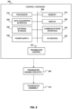
- FIG. 3 provides a block diagram illustrating an example implementation of a system for performing procedures involving focused ultrasound, such as histotripsy or HIFU.
- the control hardware 200 is operably connected to the transducer driver electronics/circuitry 260, which drives the transducer assembly 270 to generate focused ultrasound.
- the driver electronics/circuitry 260 may comprise, for example, a high-voltage single ended ultrasound pulser.
- the driver electronics/circuitry 260 may be capable of supplying over 200 volts (e.g. over 400, 600, 800 or 900 V), for example, at up to 144 amps of pulsed current, or 24 amps continuous current.
- the control hardware 200 includes one or more processors 210 (for example, a CPU/microprocessor), bus 205, memory 215, which may include random access memory (RAM) and/or read only memory (ROM), a data acquisition interface 220, a display 225, external storage 230, one more communications interfaces 235, a power supply 240, and one or more input/output devices and/or interfaces 245 (e.g. a speaker, a user input device, such as a keyboard, a keypad, a mouse, a position tracked stylus, a position tracked probe, a foot switch, and/or a microphone for capturing speech commands).
- processors 210 for example, a CPU/microprocessor
- bus 205 memory 215, which may include random access memory (RAM) and/or read only memory (ROM), a data acquisition interface 220, a display 225, external storage 230, one more communications interfaces 235, a power supply 240, and one or more input/output devices and/or interfaces 245 (e.
- the control hardware 200 may be programmed with programs, subroutines, applications or modules, such as transducer control module 255, which include executable instructions, which when executed by the one or more processors 210, causes the system to generate a series of pulses suitable for a selected type of focused ultrasound therapy. Such instructions may be stored, for example, in memory 215 and/or other storage.
- control hardware 200 may be implemented as one or more physical devices that are coupled to processor 210 through one of more communications channels or interfaces.
- control hardware 200 can be implemented using application specific integrated circuits (ASICs).
- ASICs application specific integrated circuits
- control hardware 200 can be implemented as a combination of hardware and software, where the software is loaded into the processor from the memory or over a network connection.
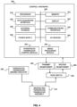
- FIG. 4 illustrates an example embodiment of a system configured for focused ultrasound therapy and imaging using a transducer assembly 272 having an integrated co-registered imaging transducer and a focused ultrasound therapeutic transducer.
- Control hardware 200 is employed to control transmit beamformer 282 and receive beamformer 284, and Tx/Rx switch 285, and for processing the beamformed receive signals.
- control hardware 200 may include an image processing module 256 for processing image data obtained using the co-registered imaging transducer.
- the example embodiments disclosed above may be employed for a wide variety of applications, such as neurological procedures.
- one of the most common methods of tumor resection in the brain is the use of burr-hole surgery, in which a hole is made in the skull and, using visual guidance as well as pre-operative MRI images, a cavitational ultrasonic surgical aspiration (CUSA) device is used to ablate the tumor tissue.
- This CUSA treatment is a contact ablation where the device cavitates and ablates tissue adjacent to the tip and the liquified tissue is then pulled away via suction.
- the systems and devices disclosed herein may be employed for focused ultrasound applications other than histotripsy.
- the systems and devices disclosed herein can be used for HIFU.
- the embodiments disclosed herein could be used for HIFU without the presence of the polymer acoustic impedance matching layer, and/or with a different lens material, and/or using a non-composite piezoelectric layer.
- the distal lens shape may be spherical in the case of HIFU applications, as HIFU does not typically require the high intensity of ultrasound that histotripsy does, and instead involves the sustained delivery of ultrasound to heat tissue.
- a small, 10 mm aperture histotripsy transducer was characterized and, following characterization, the device was modified to include a co-linear, co-registered 40 MHz imaging device to allow both imaging and ablation in real-time with a 10 mm aperture.
- the ultrasound ablation transducer described in the present example consists of an air-backed piezoelectric composite bound to an aluminum lens using epoxy, where the aluminum lens has a quarter wavelength matching layer on the front face matching to water.
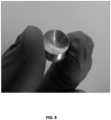
- a photograph of the assembled composite transducer and coated parabolic aluminum acoustic lens is shown in FIG. 5 .
- the piezoelectric composite was designed to provide maximum output power near 5 MHz with the composite itself being a 1-3 PZT-polymer dice- and-fill design.
- the composite was modeled using in-house Krimholtz-Leedom-Matthaei (KLM) code, which provided a design thickness of 303 ⁇ m and a pillar geometry resulting in a characteristic acoustic impedance of approximately 17 MRayls, closely matching the characteristic impedance of 6061-T6 series aluminum.
- KLM Krimholtz-Leedom-Matthaei
- the composite was attached to the aluminum lens using a thin film of Epotek 301 epoxy resin (Epoxy Technology Inc.), which is known to have an acoustic impedance of 3.05 MRayls (at 30 MHz). It is noted that this acoustic impedance is lower than the acoustic impedances of both the acoustic lens and the piezoelectric layer.
- the aluminum lens was fabricated using a CNC milling process and designed to focus at a 7 mm depth.
- the curvature of the lens was fabricated to be elliptical, as per the equation provided above.
- elliptical lens shape avoids spherical aberrations in the lens, which are important to avoid when the lens focus is smaller than the lens aperture.
- Parylene matching layer was deposited on the lens face using the Specialty Coating Systems PDS- 2010 Parylene Coater (Specialty Coating Systems Inc., Indiana USA). Parylene has a longitudinal speed of sound of 2135 m/s with an acoustic impedance of 2.75 MRayls [20], so a layer thickness of 78.2 ⁇ m was deposited to match at 6.82 MHz.
- the epoxy film thickness and properties could be chosen to modify the transducer output, where, for example, increasing film thickness attains improved acoustic power output for a given input voltage but with a reduced efficiency and bandwidth, as well as a frequency shift of the resonance.
- KLM models show the film thickness is near 20 ⁇ m, approximately doubling output power compared to having no film for a fixed drive-voltage while also shifting the maximum output frequency from 5 MHz to 6.8 MHz. This doubling of output power should result in a sqrt(2) gain in acoustic pressure at the lens focus.
- Characterization of the transducer was performed by the following methods: electrical impedance measurements both before and after lens bonding, measuring a pressure field map near the transducer focus, obtaining a measure of the peak minimum focal pressure versus drive voltage, and imaging of a single-cycle pulse generated bubble cloud.
- the experimental electrical impedance measured using an Agilent 4294A Precision Impedance Analyzer (Agilent Technologies, Santa Clara, USA), and the KLM derived electrical impedance are shown in FIGS. 6A and 6B for a 10 mm diameter disc of air backed and air loaded composite prior to attaching a lens.
- KLM code was used to model the transducer electrical impedance. This code was able to model not only a bare piezoelectric composite, but the full transducer stack which included an epoxy bonding layer and aluminum lens. To include the lens in the KLM model, the composite-lens stack was divided into a set of concentric rings of equal area, each with equal backing, composite, epoxy and Parylene layers, but with aluminum layer of varying height to account for the lens curvature varying as a function of radius.
- a ring would be modeled as having a 2 mm aluminum layer as part of the lens, while a ring at the outer edge would be modeled with a 4.4 mm aluminum layer as the lens curvature is larger at the outer edge.
- FIGS. 7A and 7B show the measured impedance and phase curves, respectively, for a transducer with the lens attached.
- the resonance peak normally seen for a composite is absent, as the lens spreads the resonances out over a wide band.
- near 8 MHz in the measured impedance is a second resonance feature corresponding to a lateral mode of the composite which is not captured in KLM, as KLM is inherently a one-dimensional model. This one-dimensional limitation also leads to difficulties in modeling the full transducer electrical impedance when a lens is introduced.
- FIGS. 7C and 7D This difficulty is demonstrated in FIGS. 7C and 7D , where a comparison is shown between the measured electrical impedance for a composite with lens attached, along with KLM models both with and without Epotek 301 between the composite and lens.
- the measured impedance magnitude in FIG. 7C shows a resonance at 5 MHz and an anti-resonance at 7 MHz; however, a KLM model with composite in direct contact to the lens shows only a decreasing impedance magnitude with increasing frequency.
- the addition of a 20 ⁇ m epoxy layer is therefore necessary to capture the measured system behavior in the model.
- Also of note are a number of small, 5 Ohm amplitude oscillatory features between 2 MHz and 7 MHz that are visible in the measured impedance.
- the impedance phase curve in FIG. 7D also shows the importance of an epoxy layer where the 20 ⁇ m epoxy layer moves the maximum phase point from 4 MHz to 6.5 MHz and increasing the value from -60 degrees to -20 degrees, again, more closely matching to the measured electrical impedance.
- FIGS. 8A and 8B the simulated electrical impedance of five transducer designs is shown, with each device having an increasing epoxy layer thickness.
- the resonance minimum point
- the anti-resonance peak
- the phase peak increases while the frequency also shifts to the left.
- the shift in frequency may be, for example, mass-spring related, or may be a resonance cavity created by the addition of the epoxy.
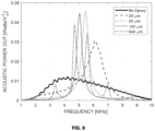
- FIG. 9 plots of the simulated acoustic power output normalized to input voltage squared show a power increase with increasing epoxy layer thickness, up to a limit.
- a quarter wavelength matching layer is added to the front transducer face with a thickness corresponding to wavelength associated with the maximum transducer output power prior to the quarter wavelength layer being added; or, in other words, the quarter wavelength layer is matched to work in tandem with the specific epoxy layer thickness.
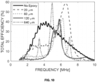
- the simulated devices having layer thickness of 60 micrometers and 120 micrometers of provide an almost identical power output, with a shifted frequency between them, while increasing further to a 640 micrometer layer creates a split output with reduced power in each band, compared to the devices with 60 and 120 micrometer layers.
- power output is increased by a factor of up to 3.75 by adding the epoxy layer.
- FIG. 10 illustrates how simulated efficiency changes as the bonding epoxy layer is widened, where it is observed that the epoxy layer increases efficiency, albeit over a narrower band of frequencies.
- FIG. 11A plots the 2D pressure profile where the - 6dB radial beam width is 0.207 mm, and the -6dB axial beam length is 1.061 mm.
- the pressure field was measured in a 5 mm x 2 mm plane intersecting the transducer focus where the plane normal vector is perpendicular to the direction of acoustic propagation.
- the 0.04 mm needle hydrophone was scanned through the pressure field, where an oscilloscope recorded the peak-negative pressure while the transducer was driven using a pulser based on the design by Brown and Lockwood [21] with a 20 cycle, 20 V, 6.8 MHz pulse.
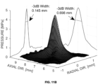
- FIG. 11B shows that the -3 dB width in the radial direction is 0.145 mm while in the axial direction the -3 dB width measures 0.698 mm.
- focal pressure as a function of drive voltage was measured to confirm the possibility of reaching the intrinsic cavitation threshold needed for histotripsy (26.1-27.9 MPa at 3 MHz in water [ E. Vlaisavljevich, K.-W. Lin, A. Maxwell, M. T. Warnez, L. Mancia, R. Singh, A. J. Putnam, B. Fowlkes, E. Johnsen, C. Cain, and Z. Xu, "Effects of ultrasound frequency and tissue stiffness on the histotripsy intrinsic threshold for cavitation," Ultrasound in Medicine and Biology, vol. 41, no. 6, pp. 1651 - 1667, 2015 ]).
- the transducer focal pressure was measured using a hydrophone as a function of drive voltage.
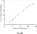
- FIG. 12A the peak-to-peak pressure versus drive voltage for the non-imaging transducer is shown.
- the measurement was limited to below 25 V as, above this, large oscillations in the hydrophone measurements were observed, which were believed to be the beginnings of cavitation, which could potentially damage the hydrophone.
- FIG. 12B shows an alternative representation of the data plotted in FIG. 12A , plotting the peak-negative pressure (the maximum negative value of pressure instead of the difference between the maximum and minimum pressure).
- the inset to FIG. 12B plots a representative one-way single-cycle pulse response as measured at the hydrophone to provide device bandwidth. Within the inset, temporal ringing following the main pulse is likely a result of reverberation within the lens, and potentially also ringing within the hydrophone which could not be uncoupled from the measurement.
- a linear relationship between pressure and drive voltage is seen from 2.5 V up to 17 V. Above 17 V, initial evidence of cavitation at the hydrophone tip was seen as noise in the oscilloscope signal. At 25 V, cavitation at the hydrophone tip made pressure measurements inconsistent and, therefore, measurements were stopped.
- the inset plot shows a one-way, single-cycle pulse response as measured with the hydrophone. The ringing after the initial pulse is due to reverberations within the lens. The pulse bandwidth was 59%.
- the transducer was driven with a 20-cycle pulse train to ensure steady-state was reached at 6.8 MHz with a pulse repetition frequency of 100 Hz.
- a minimum drive voltage of 2.3 V was needed for the drive circuit to power the transducer, after which point the pressure follows a linear trend of 0.29 MPa / V up to 25 V.
- a drive voltage of greater than 90 V should be needed for a multi-cycle pulse.
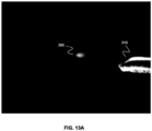
- the bubble cloud was identified visibly using a microscope, where it can be seen in FIG. 13A at 300.
- the bubble cloud was generated with a 170V, 3 cycle pulse with a 10 ms repetition rate.
- the needle tip shown the right (at 310) is a 26 gauge needle with a diameter of 0.46 mm, demonstrating that the cloud size measures ⁇ 0.2 mm diameter vertically at its smallest size.
- the bubble cloud appears blurry because a time average of frames was used while illuminating the bubble cloud to get the image.
- the cloud measures - 200um diameter at the narrowest point and -300 um along the longest axis.
- the bubble cloud size increases and cavitation action becomes more aggressive as drive voltage and number of burst cycles increases. This can be used to control the speed and amount of tissue being ablated at a time.
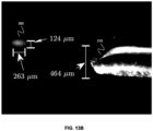
- results from subsequent measurements are shown in FIG. 13B .
- the cavitation bubble cloud is shown as a white spot here due to averaging of multiple camera frames to produce an image.
- This bubble cloud was generated in degassed, deionized water with a 6.8 MHz single-cycle, single-ended 173 V pulse at a 50 Hz repetition rate.
- a 26 gauge needle, nominal diameter 464 ⁇ m, can be seen in the image to provide scale for the bubble cloud which measures 124 ⁇ m diameter with a length of 263 ⁇ m.
- FIGS. 13A and 13B demonstrate the ability to create a bubble cloud, however, FIG. 13B involved a longer time between pulses, and was only a single-cycle pulse.
- the smaller size of the bubble in FIG. 13B can be attributed to the lower number of cycles as this makes the overall volume which exceeds cavitation pressure smaller.
- Imaging was performed using a Zeiss Discovery.V20 Stereo Microscope and a Zeiss Axiocam ERc 5s digital camera (Carl Zeiss Microscopy GmbH, Jena, Germany) where the bubble cloud was illuminated perpendicular to the direction of imaging, and multiple images were acquired and averaged to recreate the full bubble cloud shape.
- This imaging is easy to do while cavitation occurs in water; however, in tissue, visual imaging would be impossible at-depth, so the tool presented here can instead be modified with the addition of a central hole, allowing an ultrasound probe through the center to image while ablation is being performed.
- a co-registered imaging and ablation tool is described.
- the focusing lens which was schematically illustrated in FIG. 1 , was modified to add a 4 mm x 4 mm hole through the center allowing any imaging tool to image the ablation area, as illustrated in FIG. 2 .
- the imaging device employed in the present example was developed in-house, and was fabricated as a 40 MHz, 64- element phased-array transducer packaged in a 2.5 x 3.1 mm endoscopic form factor. This endoscopic phased array was fully characterized by Bezanson et. al. in 2014 [ A. Bezanson, R. Adamson, and J. A.
- FIG. 14 shows the example ultrasound endoscope with a machined lens positioned at the end as was used during co-registered ablation.
- the device may be mounted at the end of a hand-held tool for fast user guidance so that ablation points can be targeted on-the-fly if desired.
- the tight lens focus and small ablation spot-size, as well as the high-resolution endoscope imaging window renders the device as having potential for use in small animal studies where internal ablation, or highly targeted neural ablation with minimal tissue heating, may be desired.
- the configuration shown in FIG. 14 provides one example orientation of the ablation lens relative to the endoscope.
- the endoscope tip may be recessed from the lens curvature so that the endoscope does not occlude the ablation tool, while still having the ablation zone centered in the imaging window.
- the lens-composite stack may be encased to ensure the composite remains air-backed. Preliminary testing of the co-registered device found that, with the current drive electronics and the missing lens area needed to accommodate the imaging probe, a higher voltage was needed to consistently cavitate.
- FIG. 14 demonstrates this need for a higher drive voltage with a plot of pressure vs drive voltage for the transducer with a hole in the center.
- FIGS. 15A and 15B show the peak-to-peak pressure, and the peak negative pressure, respectively, versus drive voltage for the transducer with a hole for co-registration for two different measurements. It is noted that the voltage needed to reach 10 MPa was ⁇ 2.5 times larger than for the non-co-registered transducer. This is related to the transducer hole reducing the ability of the transducer to focus.
- a one-way response to a single cycle pulse at 6.8 MHz is shown in the top-left corner of FIG. 15A , where the response is good, however a tail in the response is seen.
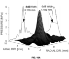
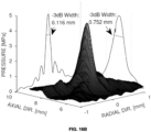
- FIGS. 16A and 16B the 2D pressure profile of the co-registered transducer is shown, with the -6 dB width shown in FIG. 16A , and the -3 dB width shown in FIG. 16B .
- the radial beam width appears to be narrower compared to the transducer without a hole, however, there is more energy in the side lobes as seen by the higher pressures off center which is caused by the transducer hole reducing the ability of the lens to focus to a single point.
- the pressure field shows visible side lobes at ⁇ 0.2 mm, 10 dB below the peak in the radial direction.
- the transducer was driven with a 20 cycle pulse train at 6.8 MHz using a pulse-repetition frequency of 50 Hz.
- pressure increased at a rate of 0.29 MPa / volt whereas for this co-registered imaging device the pressure increases at a rate of 0.1 MPa / volt.
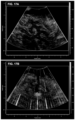
- FIGS. 17A and 17B histotripsy cavitation was performed in ex-vivo chinchilla cerebral tissue, the results of which are shown in FIGS. 17A and 17B .
- the highly specular tissue is the cerebellum granular layer
- the large dark regions are the molecular layer
- thin dark tracts which are white matter. The ability to identify these regions using ultrasound is important for targeting specific parts of the brain.
- histotripsy ablation is in progress, where the bright circular region between 7 mm and 8 mm depth is the bubble cloud in the process of ablating.
- ablation is performed by driving the transducer with a 6.8 MHZ, 400 V, single-ended 10 cycle pulse train at a pulse repetition frequency (PRF) of 1000 Hz.
- PRF pulse repetition frequency
- Above the bubble cloud a channel can be seen from the cerebellum surface down to the ablation zone, where cavitation was initiated at the surface and then plunged into the tissue.
- the bright streaks in the image are electronic noise from the histotripsy pulser and can be removed by synchronizing the histotripsy pulses to occur between image lines.
- peak pressure should be less than three times the shock scattering threshold in the treated tissue.
- the -3dB radial beam width is measured at 0.116 mm and the focal length, or -3dB axial beam width, is 0.752 mm.
- a small, 10 mm aperture imaging and ablation device can create a histotripsy bubble cloud capable of ablating tissue with a focal zone and imaging capability allowing potentially sub-millimeter ablation accuracy.
- the simplicity of the present example design should facilitate the creation of multiple tools without significant cost, while the demonstration of cavitation in water at a drive voltage of 173 V suggests driving the tool directly without matching circuitry or a transformer can keep the cost of the drive electronics low as well.
- Side lobes on the non-co-registered device and on the co-registered device are close to -20 dB and -10 dB, respectively, suggesting that the probability of cavitation outside the focus is low.
- a measured 59% one-way bandwidth allows the device to operate with a single-cycle or two-cycle pulse, maintaining a tight focus.
- the present example device and the preceding example embodiments may be employed to provide an endoscopic imaging and ablation histotripsy tool.
- Simulations were performed to investigate, for devices having an intermediate layer, the dependence of device performance on the acoustic impedance of the intermediate layer. Simulations were performed for devices having the same properties as in the previously described simulations, with an intermediate layer thickness of 20 microns, and with different values of the acoustic impedance of the intermediate layer. The simulations revealed that if the acoustic impedance of the intermediate layer is lower than that of both the piezoelectric layer and the acoustic lens, then a resonant increase in power is observed in the acoustic frequency spectrum.
- the acoustic impedance of the intermediate layer is equal to the lowest of the acoustic impedances of the acoustic lens and the piezoelectric layer, then the resonance behavior of the acoustic power spectrum with resonant peaks having increased power output is not observed. If the acoustic impedance of the intermediate layer is between that of the piezoelectric layer and acoustic lens, then a resonant increase in power is also not observed. Furthermore, if the acoustic impedance of the intermediate layer is higher than that of both the piezoelectric layer and the acoustic lens, then a slight decrease in power is observed at higher frequencies.
Landscapes
- Health & Medical Sciences (AREA)
- Engineering & Computer Science (AREA)
- Biomedical Technology (AREA)
- Nuclear Medicine, Radiotherapy & Molecular Imaging (AREA)
- Radiology & Medical Imaging (AREA)
- Life Sciences & Earth Sciences (AREA)
- Animal Behavior & Ethology (AREA)
- General Health & Medical Sciences (AREA)
- Public Health (AREA)
- Veterinary Medicine (AREA)
- Mechanical Engineering (AREA)
- Transducers For Ultrasonic Waves (AREA)
- Ultra Sonic Daignosis Equipment (AREA)
Claims (13)
- Système à ultrasons pour générer des ultrasons focalisés, le système à ultrasons comprenant :
un ensemble transducteur à ultrasons comprenant :une couche piézoélectrique (100) ;une lentille acoustique (110) ayant une surface proximale (112) et une surface distale incurvée (114), dans lequel la surface proximale est fixée à la couche piézoélectrique, ladite lentille acoustique ayant un diamètre de moins de 10 mm et un nombre f de moins de deux ;
une circuiterie pilote (260) connectée de manière fonctionnelle à l'ensemble à ultrasons ;caractérisé en ce que ledit ensemble transducteur à ultrasons comprend en outre une couche d'adaptation d'impédance acoustique (120) revêtant la surface distale incurvée de la lentille acoustique, dans lequel une impédance acoustique de la couche piézoélectrique correspond approximativement à une impédance acoustique de la lentille acoustique, et en ce que la circuiterie pilote est configurée pour délivrer des impulsions électriques avec une tension et une fréquence de fonctionnement suffisantes pour générer des impulsions ultrasonores qui produisent une cavitation dans l'eau. - Système à ultrasons selon la revendication 1, dans lequel la lentille acoustique comprend de l'aluminium.
- Système à ultrasons selon la revendication 1 ou 2, dans lequel la surface distale incurvée de la lentille acoustique est non sphérique.
- Système à ultrasons selon la revendication 3, dans lequel la surface distale incurvée de la lentille acoustique est elliptique.
- Système à ultrasons selon l'une quelconque des revendications 1 à 4, dans lequel la couche d'adaptation d'impédance acoustique est formée à partir d'un polymère compatible avec un dépôt chimique en phase vapeur.
- Système à ultrasons selon l'une quelconque des revendications 1 à 5, comprenant en outre un transducteur d'imagerie à ultrasons intégré (140) reçu et logé d'une manière coaxiale par rapport à la lentille acoustique, avec l'extrémité distale du transducteur d'imagerie émergeant à travers une ouverture formée dans la surface distale de la lentille acoustique.
- Système à ultrasons selon l'une quelconque des revendications 1 à 6, dans lequel une couche intermédiaire est prévue entre la lentille acoustique et la couche piézoélectrique, dans lequel une impédance acoustique de la couche intermédiaire est inférieure à l'impédance acoustique de la lentille acoustique et à l'impédance acoustique de la couche piézoélectrique.
- Système à ultrasons selon la revendication 7, dans lequel la couche intermédiaire est une couche adhésive liant la lentille acoustique à la couche piézoélectrique.
- Système à ultrasons selon la revendication 7 ou 8, dans lequel un spectre de puissance acoustique de celui-ci comprend un pic ayant une fréquence associée qui dépend de l'épaisseur de la couche intermédiaire.
- Système à ultrasons selon la revendication 9, dans lequel une intensité du pic dépend également de l'épaisseur de la couche intermédiaire.
- Système à ultrasons selon l'une quelconque des revendications 7 à 10, dans lequel une épaisseur de la couche intermédiaire est suffisante pour effectuer une augmentation de la puissance acoustique émise pic dans un spectre de puissance acoustique de l'ensemble transducteur à ultrasons d'un facteur d'au moins deux par rapport à une ensemble transducteur à ultrasons équivalent dépourvu de la couche intermédiaire.
- Système à ultrasons selon l'une quelconque des revendications 7 à 10, dans lequel une épaisseur de la couche intermédiaire est suffisante pour effectuer une augmentation de la puissance acoustique émise dans un spectre de puissance acoustique de l'ensemble transducteur à ultrasons d'au moins trois par rapport à un ensemble transducteur à ultrasons équivalent dépourvu de la couche intermédiaire.
- Système à ultrasons selon l'une quelconque des revendications 7 à 10, dans lequel une épaisseur de la couche intermédiaire est suffisante pour effectuer une augmentation de l'efficacité pic dans un spectre d'efficacité acoustique de l'ensemble transducteur à ultrasons d'au moins 20 % par rapport à un ensemble transducteur à ultrasons équivalent dépourvu de la couche intermédiaire.
Applications Claiming Priority (3)
| Application Number | Priority Date | Filing Date | Title |
|---|---|---|---|
| US201762553719P | 2017-09-01 | 2017-09-01 | |
| US201862629475P | 2018-02-12 | 2018-02-12 | |
| PCT/CA2018/051047 WO2019041040A1 (fr) | 2017-09-01 | 2018-08-30 | Ensemble transducteur pour générer des ultrasons focalisés |
Publications (3)
| Publication Number | Publication Date |
|---|---|
| EP3675959A1 EP3675959A1 (fr) | 2020-07-08 |
| EP3675959A4 EP3675959A4 (fr) | 2021-05-19 |
| EP3675959B1 true EP3675959B1 (fr) | 2024-11-27 |
Family
ID=65524876
Family Applications (1)
| Application Number | Title | Priority Date | Filing Date |
|---|---|---|---|
| EP18849828.1A Active EP3675959B1 (fr) | 2017-09-01 | 2018-08-30 | Ensemble transducteur pour générer des ultrasons focalisés |
Country Status (4)
| Country | Link |
|---|---|
| US (3) | US11806553B2 (fr) |
| EP (1) | EP3675959B1 (fr) |
| CA (1) | CA3073552A1 (fr) |
| WO (1) | WO2019041040A1 (fr) |
Families Citing this family (16)
| Publication number | Priority date | Publication date | Assignee | Title |
|---|---|---|---|---|
| JP7231646B2 (ja) * | 2018-03-30 | 2023-03-01 | ラブサイト インコーポレイテッド | 流体不透過性超音波トランスデューサ |
| CN113286552B (zh) | 2018-11-28 | 2025-05-02 | 希斯托索尼克斯公司 | 组织摧毁术系统及方法 |
| US20200205781A1 (en) * | 2018-12-27 | 2020-07-02 | Avent, Inc. | Miniscule Transducer for a Medical Article |
| WO2021155026A1 (fr) | 2020-01-28 | 2021-08-05 | The Regents Of The University Of Michigan | Systèmes et procédés d'immunosensibilisation par histotripsie |
| JP2023530477A (ja) | 2020-06-18 | 2023-07-18 | ヒストソニックス,インコーポレーテッド | 組織破砕音響/患者結合システムおよび方法 |
| EP4204084A4 (fr) | 2020-08-27 | 2024-10-09 | The Regents Of The University Of Michigan | Transducteur ultrasonore à capacité d'émission-réception pour l'histotripsie |
| CN112914508B (zh) * | 2021-01-22 | 2023-03-31 | 华南师范大学 | 基于椭球面曲率的光声/超声双模态高频探头 |
| EP4351718A4 (fr) | 2021-06-07 | 2025-03-26 | The Regents of The University of Michigan | Méthodes et systèmes d'histotripsie minimalement invasifs |
| IL308943A (en) * | 2021-06-07 | 2024-01-01 | Univ Michigan Regents | All-inclusive ultrasound systems and methods that include histotripsy |
| CN117753650A (zh) * | 2022-09-26 | 2024-03-26 | 重庆融海超声医学工程研究中心有限公司 | 一种超声波发生装置及方法 |
| TWI830429B (zh) * | 2022-10-11 | 2024-01-21 | 佳世達科技股份有限公司 | 換能器及應用其之超音波探頭 |
| AU2023366591A1 (en) | 2022-10-28 | 2025-04-24 | Histosonics, Inc. | Histotripsy systems and methods |
| TW202434334A (zh) * | 2022-11-14 | 2024-09-01 | 加拿大商共振聲學國際股份有限公司 | 超音波影像引導聚焦超音波系統及相關方法 |
| CN116532338B (zh) * | 2023-01-29 | 2025-05-23 | 安徽奥飞声学科技有限公司 | 一种超声换能器的制造方法 |
| WO2024221001A2 (fr) | 2023-04-20 | 2024-10-24 | Histosonics, Inc. | Systèmes d'histotripsie et procédés associés comprenant des interfaces utilisateur et des flux de travail pour la planification et la thérapie de traitement |
| CN117019608B (zh) * | 2023-10-08 | 2024-01-05 | 中北大学 | 一种高性能空气耦合超声点聚焦换能器及其制备方法 |
Citations (1)
| Publication number | Priority date | Publication date | Assignee | Title |
|---|---|---|---|---|
| US20070055183A1 (en) * | 2005-07-20 | 2007-03-08 | Ust, Inc. | Thermally enhanced ultrasound transducer means |
Family Cites Families (26)
| Publication number | Priority date | Publication date | Assignee | Title |
|---|---|---|---|---|
| US3663842A (en) | 1970-09-14 | 1972-05-16 | North American Rockwell | Elastomeric graded acoustic impedance coupling device |
| US4477783A (en) * | 1982-08-19 | 1984-10-16 | New York Institute Of Technology | Transducer device |
| US4945915A (en) * | 1987-02-20 | 1990-08-07 | Olympus Optical Co., Ltd. | Ultrasonic diagnosis apparatus |
| US4945898A (en) * | 1989-07-12 | 1990-08-07 | Diasonics, Inc. | Power supply |
| US5640961A (en) * | 1995-09-25 | 1997-06-24 | Hewlett-Packard Company | Device with aspherical compensation for focusing ultrasound |
| US5984871A (en) * | 1997-08-12 | 1999-11-16 | Boston Scientific Technologies, Inc. | Ultrasound transducer with extended focus |
| US20070055182A1 (en) | 2005-07-20 | 2007-03-08 | Ust, Inc. | Thermally enhanced ultrasound transducer method |
| US20070083120A1 (en) | 2005-09-22 | 2007-04-12 | Cain Charles A | Pulsed cavitational ultrasound therapy |
| US20080195003A1 (en) | 2007-02-08 | 2008-08-14 | Sliwa John W | High intensity focused ultrasound transducer with acoustic lens |
| US7621624B2 (en) * | 2007-05-18 | 2009-11-24 | National Central University | High-efficient ultrasonic ink-jet head and fabrication method of for the same |
| WO2009094554A2 (fr) | 2008-01-25 | 2009-07-30 | The Regents Of The University Of Michigan | Histotripsie pour thrombolyse |
| US9901753B2 (en) | 2009-08-26 | 2018-02-27 | The Regents Of The University Of Michigan | Ultrasound lithotripsy and histotripsy for using controlled bubble cloud cavitation in fractionating urinary stones |
| WO2011146139A2 (fr) | 2010-05-21 | 2011-11-24 | Misonix Incorporated | Ensemble transducteur ultrasonique |
| US20130190623A1 (en) | 2012-01-06 | 2013-07-25 | James A. Bertolina | Histotripsy Therapy Transducer |
| US9636133B2 (en) * | 2012-04-30 | 2017-05-02 | The Regents Of The University Of Michigan | Method of manufacturing an ultrasound system |
| US10149660B2 (en) | 2012-08-09 | 2018-12-11 | Dalhousie University | Ultrasound endoscope and methods of manufacture thereof |
| EP2903688A4 (fr) | 2012-10-05 | 2016-06-15 | Univ Michigan | Rétroaction par doppler couleur induite par des bulles lors d'une histotripsie |
| CA2895821A1 (fr) * | 2012-12-21 | 2014-06-26 | Volcano Corporation | Transducteur ivus rotatif focalise employant un materiau composite monocristallin |
| US10350439B2 (en) * | 2013-03-28 | 2019-07-16 | University Of Washington Through Its Center For Commercialization | Focused ultrasound apparatus and methods of use |
| US10694974B2 (en) | 2014-03-27 | 2020-06-30 | University Of Washington | Method and system for MRI-based targeting, monitoring, and quantification of thermal and mechanical bioeffects in tissue induced by high intensity focused ultrasound |
| US11045167B2 (en) * | 2014-07-12 | 2021-06-29 | University Of Southern California | Forward-looking ultrasound array probe for intravascular imaging and navigation applications |
| WO2016115638A1 (fr) | 2015-01-23 | 2016-07-28 | Dalhousie University | Systèmes et procédés de mise en forme du faisceau à l'aide d'un échantillonnage variable |
| EP4230262A3 (fr) | 2015-06-24 | 2023-11-22 | The Regents Of The University Of Michigan | Systèmes de thérapie par histotripsie pour le traitement de tissu cérébral |
| US10325768B1 (en) * | 2015-09-03 | 2019-06-18 | Labcyte Inc. | Focused acoustic radiation for rapid sequential ejection of subwavelength droplets |
| CA3007665A1 (fr) | 2016-01-18 | 2017-07-27 | Ulthera, Inc. | Dispositif a ultrasons compact possedant un reseau a ultrasons peripherique annulaire electriquement connecte a une carte de circuit imprime flexible et son procede d'assemblage |
| JP2017163330A (ja) * | 2016-03-09 | 2017-09-14 | セイコーエプソン株式会社 | 超音波デバイス、超音波モジュール、及び超音波測定装置 |
-
2018
- 2018-08-30 EP EP18849828.1A patent/EP3675959B1/fr active Active
- 2018-08-30 US US16/642,603 patent/US11806553B2/en active Active
- 2018-08-30 WO PCT/CA2018/051047 patent/WO2019041040A1/fr not_active Ceased
- 2018-08-30 CA CA3073552A patent/CA3073552A1/fr active Pending
-
2023
- 2023-10-23 US US18/382,605 patent/US20240269488A1/en not_active Abandoned
-
2025
- 2025-04-24 US US19/188,758 patent/US20260069892A1/en active Pending
Patent Citations (1)
| Publication number | Priority date | Publication date | Assignee | Title |
|---|---|---|---|---|
| US20070055183A1 (en) * | 2005-07-20 | 2007-03-08 | Ust, Inc. | Thermally enhanced ultrasound transducer means |
Also Published As
| Publication number | Publication date |
|---|---|
| US11806553B2 (en) | 2023-11-07 |
| US20260069892A1 (en) | 2026-03-12 |
| WO2019041040A1 (fr) | 2019-03-07 |
| CA3073552A1 (fr) | 2019-03-07 |
| EP3675959A1 (fr) | 2020-07-08 |
| EP3675959A4 (fr) | 2021-05-19 |
| US20200346044A1 (en) | 2020-11-05 |
| US20240269488A1 (en) | 2024-08-15 |
Similar Documents
| Publication | Publication Date | Title |
|---|---|---|
| US20240269488A1 (en) | Transducer assembly for generating focused ultrasound | |
| US20220022845A1 (en) | Focused rotational ivus transducer using single crystal composite material | |
| US10446132B2 (en) | Acoustic lens and applications thereof | |
| JP3478874B2 (ja) | 超音波フェーズドアレイ変換器及びその製造方法 | |
| CA2799717C (fr) | Transducteur ultrasonore piezocomposite bimode | |
| US20150258352A1 (en) | Frequency compounding ultrasound pulses for imaging and therapy | |
| Kim et al. | Transcranial histotripsy therapy: A feasibility study | |
| CN111184949B (zh) | 一种聚焦超声消融系统及其控制方法 | |
| Woodacre et al. | A low-cost miniature histotripsy transducer for precision tissue ablation | |
| Woodacre et al. | Fabrication and characterization of a 5 mm× 5 mm aluminum lens-based histotripsy transducer | |
| Mallay et al. | A dual-frequency lens-focused endoscopic histotripsy transducer | |
| CN108472054A (zh) | 用于内窥镜手术的手持器械 | |
| Maslakowski et al. | The characterization and assembly of an efficient, cost effective focused ultrasound transducer | |
| Cathignol et al. | Electronic beam steering of shock waves | |
| Yamada et al. | Tube-type double-parabolic-reflector ultrasonic transducer (T-DPLUS) | |
| Woodacre et al. | A 5 mm× 5 mm square, aluminum lens based histotripsy transducer: Reaching the endoscopic form factor | |
| Woodacre et al. | A low-cost 10 mm diameter histotripsy transducer for tissue ablation guided by a co-registered high-frequency endoscopic phased array | |
| Moldovan | Development of a 1D phased ultrasonic array for intravascular sonoporation | |
| Kim et al. | 2F-3 Design of 20 MHz Convex Array Transducers for High Frequency Ophthalmic Imaging | |
| EP4271278A1 (fr) | Transducteur ultrasonore pour des applications médicales | |
| dos Santos et al. | Two-dimensional ultrasonic transducer array for shear wave elastography in deep tissues: a preliminary study | |
| Rodríguez et al. | First Approximation of Simulation of Acoustic Cavitation in Microbubbles Generated by Planar Ultrasonic Transducer | |
| Fleury et al. | High intensity therapeutic ultrasound transducer performance and characterisation | |
| Qureshi et al. | Hybrid phased array transducer for transcranial ultrasound imaging and guidance of leaky Lamb waves to characterize intracerebral hemorrhage | |
| Kaczkowski et al. | High-intensity focused ultrasound (HIFU) array system for image-guided ablative therapy (IGAT) |
Legal Events
| Date | Code | Title | Description |
|---|---|---|---|
| STAA | Information on the status of an ep patent application or granted ep patent |
Free format text: STATUS: THE INTERNATIONAL PUBLICATION HAS BEEN MADE |
|
| PUAI | Public reference made under article 153(3) epc to a published international application that has entered the european phase |
Free format text: ORIGINAL CODE: 0009012 |
|
| STAA | Information on the status of an ep patent application or granted ep patent |
Free format text: STATUS: REQUEST FOR EXAMINATION WAS MADE |
|
| 17P | Request for examination filed |
Effective date: 20200312 |
|
| AK | Designated contracting states |
Kind code of ref document: A1 Designated state(s): AL AT BE BG CH CY CZ DE DK EE ES FI FR GB GR HR HU IE IS IT LI LT LU LV MC MK MT NL NO PL PT RO RS SE SI SK SM TR |
|
| AX | Request for extension of the european patent |
Extension state: BA ME |
|
| DAV | Request for validation of the european patent (deleted) | ||
| DAX | Request for extension of the european patent (deleted) | ||
| A4 | Supplementary search report drawn up and despatched |
Effective date: 20210421 |
|
| RIC1 | Information provided on ipc code assigned before grant |
Ipc: A61N 7/00 20060101AFI20210415BHEP Ipc: A61N 7/02 20060101ALI20210415BHEP Ipc: A61B 17/225 20060101ALI20210415BHEP Ipc: B06B 1/06 20060101ALI20210415BHEP |
|
| STAA | Information on the status of an ep patent application or granted ep patent |
Free format text: STATUS: EXAMINATION IS IN PROGRESS |
|
| 17Q | First examination report despatched |
Effective date: 20230612 |
|
| GRAP | Despatch of communication of intention to grant a patent |
Free format text: ORIGINAL CODE: EPIDOSNIGR1 |
|
| STAA | Information on the status of an ep patent application or granted ep patent |
Free format text: STATUS: GRANT OF PATENT IS INTENDED |
|
| INTG | Intention to grant announced |
Effective date: 20240716 |
|
| GRAS | Grant fee paid |
Free format text: ORIGINAL CODE: EPIDOSNIGR3 |
|
| GRAA | (expected) grant |
Free format text: ORIGINAL CODE: 0009210 |
|
| STAA | Information on the status of an ep patent application or granted ep patent |
Free format text: STATUS: THE PATENT HAS BEEN GRANTED |
|
| AK | Designated contracting states |
Kind code of ref document: B1 Designated state(s): AL AT BE BG CH CY CZ DE DK EE ES FI FR GB GR HR HU IE IS IT LI LT LU LV MC MK MT NL NO PL PT RO RS SE SI SK SM TR |
|
| REG | Reference to a national code |
Ref country code: GB Ref legal event code: FG4D |
|
| REG | Reference to a national code |
Ref country code: CH Ref legal event code: EP |
|
| REG | Reference to a national code |
Ref country code: DE Ref legal event code: R096 Ref document number: 602018077074 Country of ref document: DE |
|
| REG | Reference to a national code |
Ref country code: IE Ref legal event code: FG4D |
|
| P01 | Opt-out of the competence of the unified patent court (upc) registered |
Free format text: CASE NUMBER: APP_62930/2024 Effective date: 20241127 |
|
| REG | Reference to a national code |
Ref country code: LT Ref legal event code: MG9D |
|
| REG | Reference to a national code |
Ref country code: NL Ref legal event code: MP Effective date: 20241127 |
|
| PG25 | Lapsed in a contracting state [announced via postgrant information from national office to epo] |
Ref country code: HR Free format text: LAPSE BECAUSE OF FAILURE TO SUBMIT A TRANSLATION OF THE DESCRIPTION OR TO PAY THE FEE WITHIN THE PRESCRIBED TIME-LIMIT Effective date: 20241127 Ref country code: IS Free format text: LAPSE BECAUSE OF FAILURE TO SUBMIT A TRANSLATION OF THE DESCRIPTION OR TO PAY THE FEE WITHIN THE PRESCRIBED TIME-LIMIT Effective date: 20250327 Ref country code: PT Free format text: LAPSE BECAUSE OF FAILURE TO SUBMIT A TRANSLATION OF THE DESCRIPTION OR TO PAY THE FEE WITHIN THE PRESCRIBED TIME-LIMIT Effective date: 20250327 |
|
| PG25 | Lapsed in a contracting state [announced via postgrant information from national office to epo] |
Ref country code: FI Free format text: LAPSE BECAUSE OF FAILURE TO SUBMIT A TRANSLATION OF THE DESCRIPTION OR TO PAY THE FEE WITHIN THE PRESCRIBED TIME-LIMIT Effective date: 20241127 Ref country code: NL Free format text: LAPSE BECAUSE OF FAILURE TO SUBMIT A TRANSLATION OF THE DESCRIPTION OR TO PAY THE FEE WITHIN THE PRESCRIBED TIME-LIMIT Effective date: 20241127 |
|
| REG | Reference to a national code |
Ref country code: AT Ref legal event code: MK05 Ref document number: 1745161 Country of ref document: AT Kind code of ref document: T Effective date: 20241127 |
|
| PG25 | Lapsed in a contracting state [announced via postgrant information from national office to epo] |
Ref country code: BG Free format text: LAPSE BECAUSE OF FAILURE TO SUBMIT A TRANSLATION OF THE DESCRIPTION OR TO PAY THE FEE WITHIN THE PRESCRIBED TIME-LIMIT Effective date: 20241127 |
|
| PG25 | Lapsed in a contracting state [announced via postgrant information from national office to epo] |
Ref country code: ES Free format text: LAPSE BECAUSE OF FAILURE TO SUBMIT A TRANSLATION OF THE DESCRIPTION OR TO PAY THE FEE WITHIN THE PRESCRIBED TIME-LIMIT Effective date: 20241127 |
|
| PG25 | Lapsed in a contracting state [announced via postgrant information from national office to epo] |
Ref country code: NO Free format text: LAPSE BECAUSE OF FAILURE TO SUBMIT A TRANSLATION OF THE DESCRIPTION OR TO PAY THE FEE WITHIN THE PRESCRIBED TIME-LIMIT Effective date: 20250227 |
|
| PG25 | Lapsed in a contracting state [announced via postgrant information from national office to epo] |
Ref country code: LV Free format text: LAPSE BECAUSE OF FAILURE TO SUBMIT A TRANSLATION OF THE DESCRIPTION OR TO PAY THE FEE WITHIN THE PRESCRIBED TIME-LIMIT Effective date: 20241127 Ref country code: AT Free format text: LAPSE BECAUSE OF FAILURE TO SUBMIT A TRANSLATION OF THE DESCRIPTION OR TO PAY THE FEE WITHIN THE PRESCRIBED TIME-LIMIT Effective date: 20241127 Ref country code: GR Free format text: LAPSE BECAUSE OF FAILURE TO SUBMIT A TRANSLATION OF THE DESCRIPTION OR TO PAY THE FEE WITHIN THE PRESCRIBED TIME-LIMIT Effective date: 20250228 |
|
| PG25 | Lapsed in a contracting state [announced via postgrant information from national office to epo] |
Ref country code: PL Free format text: LAPSE BECAUSE OF FAILURE TO SUBMIT A TRANSLATION OF THE DESCRIPTION OR TO PAY THE FEE WITHIN THE PRESCRIBED TIME-LIMIT Effective date: 20241127 |
|
| PG25 | Lapsed in a contracting state [announced via postgrant information from national office to epo] |
Ref country code: RS Free format text: LAPSE BECAUSE OF FAILURE TO SUBMIT A TRANSLATION OF THE DESCRIPTION OR TO PAY THE FEE WITHIN THE PRESCRIBED TIME-LIMIT Effective date: 20250227 |
|
| PG25 | Lapsed in a contracting state [announced via postgrant information from national office to epo] |
Ref country code: SM Free format text: LAPSE BECAUSE OF FAILURE TO SUBMIT A TRANSLATION OF THE DESCRIPTION OR TO PAY THE FEE WITHIN THE PRESCRIBED TIME-LIMIT Effective date: 20241127 |
|
| PG25 | Lapsed in a contracting state [announced via postgrant information from national office to epo] |
Ref country code: DK Free format text: LAPSE BECAUSE OF FAILURE TO SUBMIT A TRANSLATION OF THE DESCRIPTION OR TO PAY THE FEE WITHIN THE PRESCRIBED TIME-LIMIT Effective date: 20241127 |
|
| PG25 | Lapsed in a contracting state [announced via postgrant information from national office to epo] |
Ref country code: EE Free format text: LAPSE BECAUSE OF FAILURE TO SUBMIT A TRANSLATION OF THE DESCRIPTION OR TO PAY THE FEE WITHIN THE PRESCRIBED TIME-LIMIT Effective date: 20241127 |
|
| PG25 | Lapsed in a contracting state [announced via postgrant information from national office to epo] |
Ref country code: RO Free format text: LAPSE BECAUSE OF FAILURE TO SUBMIT A TRANSLATION OF THE DESCRIPTION OR TO PAY THE FEE WITHIN THE PRESCRIBED TIME-LIMIT Effective date: 20241127 |
|
| PG25 | Lapsed in a contracting state [announced via postgrant information from national office to epo] |
Ref country code: SK Free format text: LAPSE BECAUSE OF FAILURE TO SUBMIT A TRANSLATION OF THE DESCRIPTION OR TO PAY THE FEE WITHIN THE PRESCRIBED TIME-LIMIT Effective date: 20241127 |
|
| PG25 | Lapsed in a contracting state [announced via postgrant information from national office to epo] |
Ref country code: CZ Free format text: LAPSE BECAUSE OF FAILURE TO SUBMIT A TRANSLATION OF THE DESCRIPTION OR TO PAY THE FEE WITHIN THE PRESCRIBED TIME-LIMIT Effective date: 20241127 |
|
| PG25 | Lapsed in a contracting state [announced via postgrant information from national office to epo] |
Ref country code: IT Free format text: LAPSE BECAUSE OF FAILURE TO SUBMIT A TRANSLATION OF THE DESCRIPTION OR TO PAY THE FEE WITHIN THE PRESCRIBED TIME-LIMIT Effective date: 20241127 |
|
| REG | Reference to a national code |
Ref country code: DE Ref legal event code: R097 Ref document number: 602018077074 Country of ref document: DE |
|
| PG25 | Lapsed in a contracting state [announced via postgrant information from national office to epo] |
Ref country code: SE Free format text: LAPSE BECAUSE OF FAILURE TO SUBMIT A TRANSLATION OF THE DESCRIPTION OR TO PAY THE FEE WITHIN THE PRESCRIBED TIME-LIMIT Effective date: 20241127 |
|
| PLBE | No opposition filed within time limit |
Free format text: ORIGINAL CODE: 0009261 |
|
| STAA | Information on the status of an ep patent application or granted ep patent |
Free format text: STATUS: NO OPPOSITION FILED WITHIN TIME LIMIT |
|
| REG | Reference to a national code |
Ref country code: CH Ref legal event code: L10 Free format text: ST27 STATUS EVENT CODE: U-0-0-L10-L00 (AS PROVIDED BY THE NATIONAL OFFICE) Effective date: 20251008 |
|
| PGFP | Annual fee paid to national office [announced via postgrant information from national office to epo] |
Ref country code: DE Payment date: 20250722 Year of fee payment: 8 |
|
| PGFP | Annual fee paid to national office [announced via postgrant information from national office to epo] |
Ref country code: GB Payment date: 20250721 Year of fee payment: 8 |
|
| PGFP | Annual fee paid to national office [announced via postgrant information from national office to epo] |
Ref country code: FR Payment date: 20250722 Year of fee payment: 8 |
|
| 26N | No opposition filed |
Effective date: 20250828 |
|
| REG | Reference to a national code |
Ref country code: CH Ref legal event code: H13 Free format text: ST27 STATUS EVENT CODE: U-0-0-H10-H13 (AS PROVIDED BY THE NATIONAL OFFICE) Effective date: 20260324 |
|
| PG25 | Lapsed in a contracting state [announced via postgrant information from national office to epo] |
Ref country code: MC Free format text: LAPSE BECAUSE OF FAILURE TO SUBMIT A TRANSLATION OF THE DESCRIPTION OR TO PAY THE FEE WITHIN THE PRESCRIBED TIME-LIMIT Effective date: 20241127 |
|
| PG25 | Lapsed in a contracting state [announced via postgrant information from national office to epo] |
Ref country code: LU Free format text: LAPSE BECAUSE OF NON-PAYMENT OF DUE FEES Effective date: 20250830 |
|
| REG | Reference to a national code |
Ref country code: GB Ref legal event code: 732E Free format text: REGISTERED BETWEEN 20260319 AND 20260325 |
|
| PG25 | Lapsed in a contracting state [announced via postgrant information from national office to epo] |
Ref country code: CH Free format text: LAPSE BECAUSE OF NON-PAYMENT OF DUE FEES Effective date: 20250831 |