EP3676054B1 - Machine-outil portative - Google Patents
Machine-outil portative Download PDFInfo
- Publication number
- EP3676054B1 EP3676054B1 EP18759936.0A EP18759936A EP3676054B1 EP 3676054 B1 EP3676054 B1 EP 3676054B1 EP 18759936 A EP18759936 A EP 18759936A EP 3676054 B1 EP3676054 B1 EP 3676054B1
- Authority
- EP
- European Patent Office
- Prior art keywords
- gear
- actuating
- switching
- gearbox
- machine tool
- Prior art date
- Legal status (The legal status is an assumption and is not a legal conclusion. Google has not performed a legal analysis and makes no representation as to the accuracy of the status listed.)
- Active
Links
Images



Classifications
-
- B—PERFORMING OPERATIONS; TRANSPORTING
- B25—HAND TOOLS; PORTABLE POWER-DRIVEN TOOLS; MANIPULATORS
- B25F—COMBINATION OR MULTI-PURPOSE TOOLS NOT OTHERWISE PROVIDED FOR; DETAILS OR COMPONENTS OF PORTABLE POWER-DRIVEN TOOLS NOT PARTICULARLY RELATED TO THE OPERATIONS PERFORMED AND NOT OTHERWISE PROVIDED FOR
- B25F5/00—Details or components of portable power-driven tools not particularly related to the operations performed and not otherwise provided for
- B25F5/001—Gearings, speed selectors, clutches or the like specially adapted for rotary tools
-
- B—PERFORMING OPERATIONS; TRANSPORTING
- B23—MACHINE TOOLS; METAL-WORKING NOT OTHERWISE PROVIDED FOR
- B23B—TURNING; BORING
- B23B45/00—Hand-held or like portable drilling machines, e.g. drill guns; Equipment therefor
- B23B45/008—Gear boxes, clutches, bearings, feeding mechanisms or like equipment
-
- B—PERFORMING OPERATIONS; TRANSPORTING
- B25—HAND TOOLS; PORTABLE POWER-DRIVEN TOOLS; MANIPULATORS
- B25F—COMBINATION OR MULTI-PURPOSE TOOLS NOT OTHERWISE PROVIDED FOR; DETAILS OR COMPONENTS OF PORTABLE POWER-DRIVEN TOOLS NOT PARTICULARLY RELATED TO THE OPERATIONS PERFORMED AND NOT OTHERWISE PROVIDED FOR
- B25F5/00—Details or components of portable power-driven tools not particularly related to the operations performed and not otherwise provided for
- B25F5/02—Construction of casings, bodies or handles
-
- F—MECHANICAL ENGINEERING; LIGHTING; HEATING; WEAPONS; BLASTING
- F16—ENGINEERING ELEMENTS AND UNITS; GENERAL MEASURES FOR PRODUCING AND MAINTAINING EFFECTIVE FUNCTIONING OF MACHINES OR INSTALLATIONS; THERMAL INSULATION IN GENERAL
- F16H—GEARING
- F16H3/00—Toothed gearings for conveying rotary motion with variable gear ratio or for reversing rotary motion
- F16H3/44—Toothed gearings for conveying rotary motion with variable gear ratio or for reversing rotary motion using gears having orbital motion
- F16H3/62—Gearings having three or more central gears
- F16H3/66—Gearings having three or more central gears composed of a number of gear trains without drive passing from one train to another
- F16H3/663—Gearings having three or more central gears composed of a number of gear trains without drive passing from one train to another with conveying rotary motion between axially spaced orbital gears, e.g. a stepped orbital gear or Ravigneaux
-
- B—PERFORMING OPERATIONS; TRANSPORTING
- B25—HAND TOOLS; PORTABLE POWER-DRIVEN TOOLS; MANIPULATORS
- B25B—TOOLS OR BENCH DEVICES NOT OTHERWISE PROVIDED FOR, FOR FASTENING, CONNECTING, DISENGAGING, OR HOLDING
- B25B21/00—Portable power-driven screw or nut setting or loosening tools; Attachments for drilling apparatus serving the same purpose
-
- F—MECHANICAL ENGINEERING; LIGHTING; HEATING; WEAPONS; BLASTING
- F16—ENGINEERING ELEMENTS AND UNITS; GENERAL MEASURES FOR PRODUCING AND MAINTAINING EFFECTIVE FUNCTIONING OF MACHINES OR INSTALLATIONS; THERMAL INSULATION IN GENERAL
- F16H—GEARING
- F16H2200/00—Transmissions for multiple ratios
- F16H2200/003—Transmissions for multiple ratios characterised by the number of forward speeds
- F16H2200/0043—Transmissions for multiple ratios characterised by the number of forward speeds the gear ratios comprising four forward speeds
-
- F—MECHANICAL ENGINEERING; LIGHTING; HEATING; WEAPONS; BLASTING
- F16—ENGINEERING ELEMENTS AND UNITS; GENERAL MEASURES FOR PRODUCING AND MAINTAINING EFFECTIVE FUNCTIONING OF MACHINES OR INSTALLATIONS; THERMAL INSULATION IN GENERAL
- F16H—GEARING
- F16H2200/00—Transmissions for multiple ratios
- F16H2200/20—Transmissions using gears with orbital motion
- F16H2200/2002—Transmissions using gears with orbital motion characterised by the number of sets of orbital gears
- F16H2200/2007—Transmissions using gears with orbital motion characterised by the number of sets of orbital gears with two sets of orbital gears
-
- F—MECHANICAL ENGINEERING; LIGHTING; HEATING; WEAPONS; BLASTING
- F16—ENGINEERING ELEMENTS AND UNITS; GENERAL MEASURES FOR PRODUCING AND MAINTAINING EFFECTIVE FUNCTIONING OF MACHINES OR INSTALLATIONS; THERMAL INSULATION IN GENERAL
- F16H—GEARING
- F16H2200/00—Transmissions for multiple ratios
- F16H2200/20—Transmissions using gears with orbital motion
- F16H2200/203—Transmissions using gears with orbital motion characterised by the engaging friction means not of the freewheel type, e.g. friction clutches or brakes
- F16H2200/2035—Transmissions using gears with orbital motion characterised by the engaging friction means not of the freewheel type, e.g. friction clutches or brakes with two engaging means
Definitions
- the invention relates to a hand-held machine tool with a drive motor, a gear box and a tool holder, wherein a motor output of the drive motor is rotationally coupled to a gear drive of the gear box and a gear output of the gear box, which can be rotated about an axis of rotation, is rotationally coupled to the tool holder, wherein the gear box has a first switching gear element and a second switching gear element, which can each be linearly adjusted between a first setting position and a second setting position with respect to a gear housing using an actuating device, wherein the actuating device is coupled to the switching gear elements and has an actuating member which is pivotably mounted about an actuating pivot axis with respect to a machine housing of the hand-held machine tool and can be manually actuated by an operator of the hand-held machine tool, wherein the first switching gear element can be adjusted linearly along its setting axis by a pivoting movement of the actuating member about the actuating pivot axis using a deflection gear, wherein
- Such a hand-held machine tool is, for example, in EP 1 886 769 A1
- the hand-held power tool has a four-speed gearbox, in which two ring gears are present as switching gear elements. Each ring gear or switching gear element can be switched by an actuating device of the hand-held power tool, with both ring gears in the gearbox housing linearly adjusted. A complex actuation device is required for individual actuation of the ring gears.
- a hand-held machine tool according to the preamble of claim 1 with a four-speed gearbox is disclosed.
- the four-speed gearbox can be switched by an actuating device that is rotatable and linearly adjustable.
- a deflection gear is required to convert a rotary movement of the actuating device into a linear movement of a switching gear element. Both switching gear elements must be controlled individually by the actuating device.
- the driving ring forms a rotating body or a pivot bearing for the actuating element.
- the actuating element can thus pivot around the gearbox housing with the driving ring in order to switch the first gearshift element.
- the actuating element is in turn mounted on this driving ring in a linearly displaceable manner so that it can directly carry out the linear movement for adjusting the second gearshift element.
- a further slide or carrier for the actuating element or the second coupling element is not necessary.
- the actuating device and the coupling between the actuating device and the gearshift elements are constructed more simply.
- only a single coupling element, the second coupling element is sufficient between the actuating element and the second gearshift element. This can even be formed integrally onto the actuating element if a corresponding degree of rotational freedom is present between the second coupling element and the second gearshift element.
- a spring arrangement is expediently arranged between the actuating member and the first switching gear element or the second switching gear element or both. During and/or after actuation of the actuating member, the spring arrangement loads the switching gear element into its respective setting position or a setting position associated with the position of the actuating member. If the switching gear element cannot reach its setting position, for example because its teeth are not aligned with the teeth of a gear wheel that interacts with the switching gear element, the spring load ensures that the two components can engage with each other in a form-fitting manner when the switching gear element and gear wheel are rotated relative to each other.
- the spring arrangement between the second gearshift element and the actuating member can be provided in particular by the second coupling element, for example exclusively by the second coupling element. However, it is also possible for a separate spring or spring arrangement to be present. Furthermore, a spring arrangement and the spring coupling element However, the spring arrangement between the first gearshift element and the actuating member can also be provided by the first coupling element.
- the first coupling element or the second coupling element or both can comprise or be a spring element, for example.
- a spring clip or the like is suitable as a resilient, flexible coupling element, e.g. as in EP 1 886 769 B1 described.
- the first coupling element and/or the second coupling element expediently comprises a spring clip or is formed by a spring clip.
- the spring clip expediently extends in a ring shape around the first gearshift element or the second gearshift element.
- the spring clip can, for example, have clip arms that are resiliently flexible.
- the spring clip expediently engages with its longitudinal end regions in corresponding receptacles, for example holes, grooves, guides, in particular longitudinal guides or the like, on the respective first or second gearshift element.
- a favorable and simple embodiment provides that the actuating member is coupled to the second gearshift element exclusively by the second coupling element or by a single component. Therefore, no further component is necessary between the gearshift element and the actuating member.
- the spring clip mentioned above is suitable as a second coupling element, which is sufficient as a single component to realize the coupling between the actuating member and the second gearshift element.
- a transmission member for example annular, rod-shaped or similarly designed, is arranged between the driving ring and the first coupling element, which can be carried around the actuating pivot axis by the driving ring.
- the transmission member and the driving ring are movable relative to one another, for example, can be rotated and/or displaced relative to one another.
- a spring arrangement that can be actuated by a relative movement of the transmission member and the driving ring for spring loading the first actuating gear element into at least one switching position.
- the driving ring can therefore already reach a rotational end position while the transmission member has not yet reached this end position and is loaded into the end position by the spring element or the spring arrangement. If the first actuating gear element has a suitable position in relation to a component to be switched, for example a gear wheel, it is pressed or adjusted into this end position by the spring arrangement.
- At least one guide slot for redirecting the movement of the actuating member about the actuating pivot axis into a linear movement of the first actuating gear element is expediently arranged on the driving ring or on a transmission member that can be moved around the actuating pivot axis by the driving ring, for example the aforementioned transmission member that is adjustable relative to the driving ring.
- two guide slots are provided, which are arranged on opposite sides of the gear housing or the gear holding structure.
- the second coupling element is expediently mounted so that it can pivot and/or slide relative to the gear housing. It is therefore possible for the second coupling element, which is adjusted linearly, to transfer the linear movement to the second actuating gear element due to a displacement relative to the gear housing.
- a pivot bearing or a combined pivot bearing and sliding bearing of the second coupling element is also possible.
- the second coupling element is expediently pivotally mounted on a pivot bearing provided on the gearbox housing, for example a bearing pin protruding from a peripheral wall of the gearbox housing or a bearing receptacle arranged in the peripheral wall of the gearbox housing.
- the second coupling element can also be pivotally mounted on the actuating member as an alternative or in addition.
- the bearing receptacle can be implemented, for example, by a longitudinal groove. This longitudinal groove can also be the arcuate guide receptacle described below. If bearing pins or bearing receptacles are provided on the gearbox housing, they are expediently provided on opposite sides of the gearbox housing and/or on an area of the largest circumference of the gearbox housing. The bearing pins therefore protrude, for example, radially in front of the peripheral wall of the gearbox housing.
- the actuating member expediently has a guide receptacle which extends in an arc around the actuating pivot axis and into which the second coupling element engages.
- the second coupling element has a straight or arcuate section which engages in the aforementioned guide receptacle. It is possible for the guide receptacle to also have sufficient depth so that an arcuate free space for movement is present into which the second coupling element can engage when it pivots around the actuating pivot axis.
- a locking arrangement which serves to lock the actuating member in at least one actuating position.
- the locking arrangement has, for example, a locking receptacle or an arrangement of several locking receptacles on the actuating member.
- the locking arrangement is arranged in a concealed manner.
- the locking arrangement is provided on an underside of the actuating member and/or arranged between the actuating member and the gear housing.
- one or more locking receptacles can be provided on the actuating member, into which a locking member, in particular a spring-loaded or resilient locking member, engages, which is arranged on the gear housing.
- the resilient locking member can also be arranged on the actuating member and engage in locking receptacles on the gear housing.
- the actuating member can thus be locked in the actuating position assigned to a respective switching position of the transmission, for example in the respective Longitudinal end positions with respect to the actuating longitudinal axis and/or a pivoting position with respect to the actuating pivoting axis.
- the actuating member is expediently mounted on a linear guide of the driving ring so that it can move linearly.
- the driving ring therefore has a linear guide which has one or more guide grooves or similar other linear guide elements.
- Linear guide projections can also be provided, for example longitudinal ribs or the like, which protrude from the driving ring and engage in corresponding longitudinal guide grooves of the actuating member. Linear guide components are therefore present on the driving ring and on the actuating member.
- a further embodiment provides that the actuating member is guided on a machine housing of the hand-held power tool.
- a wall of the machine housing has a recess or cutout in which the actuating member is arranged.
- Guide receptacles in particular guide grooves, pockets or the like, can be provided on one or more edge areas of the cutout for guiding the actuating member.
- the second coupling element expediently engages in a recess in the linear guide.
- the linear guide has linear guide sections between which the recess is arranged.
- the linear guide sections are expediently connected by connecting sections.
- the second coupling element engages between the connecting sections and the actuating member.
- the linear guide expediently comprises two linear guide sections arranged at an angular distance from one another with respect to the actuating pivot axis.
- the actuating member can therefore be guided on two or more linear guide sections, which can also be interrupted, for example because of the aforementioned recess.
- the actuating member expediently has at least one support section for support on the gear housing.
- the actuating member is therefore supported on the one hand on the driving ring and on the other hand on the gear housing.
- the actuating member has an arched or barrel-shaped wall shape. It is therefore advantageous if the actuating member covers the components to be actuated by it and/or the locking arrangement.
- a further embodiment can provide that the actuating member connects spaced-apart longitudinal end regions of the driving ring to one another.
- the driving ring therefore has a distance between its longitudinal end regions, which is bridged by the actuating member.
- the actuating member engages in linear guide sections arranged on the longitudinal end region, so that these are connected to one another in relation to the actuating pivot axis. The actuating member closes the driving ring, so to speak.
- the driving ring can be a closed ring, i.e. it completely encloses the gearbox housing.
- the driving ring can be only a partial ring.
- the driving ring can therefore be designed as a ring segment.
- the driving ring preferably extends around at least half of the outer circumference of the gearbox housing, i.e. at least 180 degrees. It is preferred if the driving ring extends around at least 270 to 300 degrees of the outer circumference of the gearbox housing.
- the transmission can be switched between at least two switching positions in which speed ratios between the transmission input and the transmission output are different from one another
- the transmission comprises a first transmission wheel arrangement and at least one second transmission wheel arrangement, each of which has at least one transmission wheel and a switching transmission element, one of which is the switching actuator and the other is the switching transmission element switchable by the switching actuator
- the at least one transmission wheel is on the Switching gear element of the gear arrangement and/or the switching gear element can roll on the at least one gear of the gear arrangement and the respective switching gear element is mounted on the gear holding structure so as to be locally adjustable between at least two setting positions for setting the switching positions of the transmission and/or is adjustable with respect to the gear holding structure between an immovable position and a movable position
- the switching gear element of the first gear arrangement forms a switching actuator for the second gear arrangement which can be switched between a first setting position and at least one second setting position in which a mobility of the switching gear element
- the switching gear element of the first gear arrangement acts as a switching element directly for the first gear arrangement, but also directly or indirectly influences the rotational behavior of the second gear arrangement, which can in itself be switched by its own switching gear element.
- the switching actuator can be directly engaged with one or more gears of the second gear arrangement, for example firmly coupling or coupling a planetary gear set with the second gear arrangement with a planetary gear set of the first gear arrangement, which forms or comprises the at least one gear of the first gear arrangement.
- the planetary gear sets are then no longer rotatable relative to one another and are coupled to one another in a rotationally fixed manner by the switching gear element, for example a ring gear.
- the switching actuator i.e. the switching gear element of the first gear arrangement
- the switching transmission element of the second transmission arrangement is rotatable with respect to the transmission housing.
- the second switching transmission element can, for example, form a rolling base for the at least one gear wheel of the second gear wheel arrangement, which can roll accordingly on the second switching transmission element.
- the switching transmission elements and the gear wheels of the gear wheel arrangements are gears.
- the invention would also be possible with a roller gear transmission or friction gear transmission.
- the invention makes it possible for only the switching gear element of the first gear arrangement to be adjusted in order to switch not only the first gear arrangement but also the second gear arrangement.
- This makes operation much easier.
- an actuating device is easier to construct that only has to be coupled to the switching gear element of the first gear arrangement or controls it in order to act not only on the first gear arrangement but also on the second gear arrangement.
- this means that a housing opening on a transmission housing of the transmission can be omitted, which would otherwise be necessary for controlling or operating the switching gear element of the second gear arrangement.
- One configuration can provide that the switching gear element of the second gear arrangement is rotationally fixed in the first setting position of the switching actuator with respect to the gear holding structure, i.e. for example the gear housing, and is rotatable in the second setting position with respect to the gear holding structure.
- planetary gears i.e. the at least one gear of the second gear arrangement
- the at least one gear for example a planetary gear
- the second gear arrangement entrains or rotates the gearshift element.
- the gearshift element of the second gear arrangement advantageously has at least one anti-twisting contour for engagement in a positive-locking counter-contour of the gearshift holding structure and/or the gearshift element forming the shift actuator for the purpose of being fixed in a rotationally fixed manner with respect to the gear holding structure, for example the gear housing.
- the anti-twisting contour and the positive-locking counter-contour can be, for example, a pairing of teeth and tooth spaces or tooth receptacles, a pairing of anti-twisting projection and anti-twisting receptacle, a groove structure or the like.
- the gearshift element of the second gear arrangement can have several anti-twisting contours or anti-twisting contours located on different sides, so that it can be fixed in a positive-locking manner to several components, for example to a positive-locking counter-contour of the gear housing fixed to the housing and/or to the shift actuator.
- the anti-twisting contour is arranged on a radial outer circumference, on one end face or on both sides of the gearshift element that can be switched by the switching actuator. Tooth structures can be provided there, for example.
- the switching gear element which forms the switching actuator can have an arcuate toothing on its inner circumference as a positive-locking counter-contour, with which the anti-twisting contour of the switching gear element which can be switched by the switching actuator is in engagement in the first setting position and with which at least one gear wheel of the first gear wheel arrangement, for example its radial outer toothing, is in engagement in the second setting position.
- this gear wheel meshes with the switching gear element or switching actuator.
- the switching gear element forming the switching actuator is completely disengaged from the at least one gear wheel the first gear arrangement, in particular out of direct engagement with the at least one gear of the first gear arrangement or all gears of the first gear arrangement.
- the switching gear element therefore only fulfills the function of a switching actuator for the other switching gear element, the switching gear element of the second gear arrangement.
- the switching transmission element of the first gear arrangement is in engagement with the at least one gear of the first gear arrangement, for example a planetary gear set or at least two planetary gears, of the first gear arrangement when the switching actuator assumes the first switching position.
- This is a possible configuration, for example, in the case of a coupling of planetary gear sets that form components of the first gear arrangement and the second gear arrangement.
- the shift transmission element of the at least one second gear arrangement i.e. the switched shift transmission element
- the shift transmission element of the second gear arrangement can therefore rotate in the second setting position of the shift actuator and thus be carried along by the one or more gears of the second gear arrangement.
- the switching gear element that can be switched by the switching actuator is expediently mounted so that it can rotate with respect to the transmission support structure.
- it can also be accommodated on or in the transmission support structure in a linearly immovable manner.
- the switching gear element of the second gear arrangement is immovable with respect to a rotational axis of the transmission output of the transmission or its own rotational axis.
- a bearing arranged on the gear housing or the gear holding structure can be provided, for example a bearing groove and a bearing projection, a roller bearing, in particular a nail bearing, ball bearing or the like.
- a support body is arranged stationary with respect to the gear holding structure, on the outer circumference and/or inner circumference of which the switching gear element of the second gear arrangement is rotatably mounted.
- the at least one gear of the second gear arrangement can also be provided for the rotatable mounting of the switching gear element.
- the switching gear element of the second gear arrangement can therefore be rotatably mounted on one or more gears of the second gear arrangement or by means of the gears. This is possible, for example, if the switching gear element of the second gear arrangement is designed as a ring gear that surrounds a planetary gear set in a ring shape and is mounted on the planetary gear set.
- the switching gear element of the second gear arrangement can only be switched or actuated by the switching gear element that forms the switching actuator or the switching gear element of the first gear arrangement.
- An actuating device that can be actuated directly by the operator from an outside of the machine housing, for example, is therefore only coupled to the switching gear element of the second gear arrangement via the switching gear element of the first gear arrangement and/or not directly.
- the switching gear element forming the switching actuator is expediently mounted linearly with respect to the transmission support structure, for example parallel to a rotation axis of the transmission drive and/or the transmission output or its own rotation axis, between the first setting position and the second setting position.
- the switching gear element forming the switching actuator is expediently pivot point in one, two or more, in particular setting positions with respect to the transmission support structure. It is possible that the so-called the switching gear element of the first gear arrangement is rotatable in a setting position, for example in an intermediate setting position which is located between two further setting positions. The operator can thus bring the switching actuator from a rotationally fixed setting position into a rotatable setting position with respect to the gear housing or the gear support structure, for example by adjusting it linearly, rotating it or the like.
- gearshift element of the second gear arrangement can be spring-loaded into one or both of the first and second setting positions by a spring arrangement. If, for example, the teeth of one of the gearshift elements do not match the respective gear of the first or second gear arrangement to be switched or mesh with it, the spring load ensures that the respective teeth slide into one another when the teeth fit together.
- the gear wheels of the first gear arrangement and the at least one second gear arrangement that are or can be brought into rolling engagement with the switching transmission elements are expediently different in terms of their diameter and/or have different rolling circumferences in terms of their diameter for rolling engagement with the respectively assigned switching transmission element. This allows different speed ratios between the transmission input and the transmission output to be set favorably.
- a radial outer circumference of the switching gear element of the second gear arrangement is aligned with the radial outer circumference of the at least one gear of the first gear arrangement, so that the switching gear element forming the switching actuator can be adjusted linearly, in particular parallel to a rotational axis of the gear, between the outer circumferences of the switching gear element of the second gear arrangement and the at least one gear of the first gear arrangement.
- the switching gear element of the second gear arrangement is i.e., it does not project radially outwards in front of the at least one gear wheel of the first gear wheel arrangement, but is aligned with it.
- this alignment is to be understood in such a way that an angular offset can certainly be present between the form-fitting contours, for example teeth, of the switching gear element to be adjusted linearly and the switching gear element of the second gear wheel arrangement or the at least one gear wheel of the first gear wheel arrangement, which is, however, canceled out with further movement of the gear in such a way that the linear adjustment of the switching gear element is possible.
- the switching transmission element of the second gear arrangement is a ring gear which is arranged on the outer circumference of one or more planetary gears of the second gear arrangement and has a toothing on its outer circumference which has the same tooth geometry as the at least one gear, in particular planetary gear, of the first gear arrangement, and is aligned with the gear of the first gear arrangement, so that the switching transmission element designed as a ring gear and serving as a switching actuator is linearly adjustable between the outer circumferences of the ring gear of the second gear arrangement and the at least one gear of the first gear arrangement.
- the gear wheels of the first gear wheel arrangement and the at least one second gear wheel arrangement that are or can be brought into rolling engagement with the transmission elements are, for example, connected to one another in a rotationally fixed manner or are integral. They can also form stepped gears or stepped planetary gears.
- gear wheels of the first gear arrangement and the at least one second gear arrangement which are or can be brought into rolling engagement with the transmission elements are separated from one another, but are arranged on a common planetary gear carrier or web.
- a further embodiment of the invention provides that the gear drive is connected or coupled in a rotationally fixed manner to a sun gear, which is in rolling engagement with the at least one gear wheel of the first gear wheel arrangement. It would also be conceivable, however, that the sun gear is connected to one or more gears, for example planetary gears, of the second gear arrangement.
- the gear wheels of the first gear wheel arrangement and the second gear wheel arrangement can be arranged on a common planetary gear carrier or web, but also on separate planetary gear carriers or webs, in particular those that are rotatable relative to one another or movable relative to one another.
- the first gear arrangement and the second gear arrangement expediently form a first gear stage, wherein the transmission has at least one second gear stage, for example a planetary stage.
- the first gear stage is connected upstream or downstream of the second gear stage in relation to the transmission output.
- the gear stages are therefore arranged sequentially one behind the other.
- the second gear stage can be a gear stage that provides a fixed speed ratio, i.e. it can only be a speed-reducing or a speed-increasing gear stage that cannot be switched.
- a switchable configuration is preferred.
- the second gear stage can expediently be switched between at least two switching positions in which a speed ratio between an input of the second gear stage and an output of the second gear stage is different. In this way, for example, a four-speed transmission can be realized.
- the gear is preferably a planetary gear.
- other gear types are also possible.
- the first and/or the second actuating gear element expediently comprises a ring gear or is formed by a ring gear.
- the embodiment of the invention described in more detail below in the drawing shows a screwing machine or drilling machine.
- the invention can also be used with other hand-held machine tools, for example Milling machines, cutting machines, saws, grinding machines, polishing machines or the like.
- the gear mechanism and/or the actuating device according to the invention can also be used, for example, in hand-held machine tools that have an oscillatory-driven tool holder that moves back and forth in a linear manner, for example.
- the hand-held power tool expediently has a tool holder for a working tool and/or a working tool, for example a drilling tool, screwing tool or the like. However, a cutting tool, milling tool or the like can also be provided.
- the gear output of the gearbox is expediently coupled directly to a tool holder of the hand-held machine tool.
- a tool holder of the hand-held machine tool For example, a holder for a screwdriver bit, a drill chuck, screw chuck or similar other tool chuck can be provided.
- an impact mechanism is arranged on the gear output, for example an axial impact mechanism.
- a deflection gear is present between the gear and a tool holder of the hand-held machine tool, for example an angle gear or a conversion gear, which converts the rotating output movement of the gear output into an oscillatory linear movement or a hypercycloid and/or eccentric movement of the tool holder.
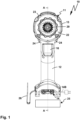
- a hand-held power tool 10 for example a screwing device, has a machine housing 11, which is preferably designed like a pistol. An operator can grasp the machine housing 11 and thus the hand-held power tool 10 by a handle section 12 that protrudes from a motor section 13 of the machine housing 11. An energy storage interface 14 is provided on a foot area or on the free end area of the handle section 12 that is remote from the motor section 13, to which an energy storage device 25, for example a battery pack, can be attached.
- the hand-held power tool 10 can therefore be operated independently and wirelessly, although this is not important.
- a hand-held power tool with a mains connection 14B for an alternating current network in particular a connection cable with a plug and/or a socket for a connection cable, in particular a mains cable, or a hand-held power tool with an energy storage interface and mains connection, would also be possible without further ado.
- the energy storage interface 14 supplies a power supply device 15 with electrical energy.
- the power supply device 15 can be actuated using a switch 16, which is preferably arranged on the handle section 12, in order to supply current to a drive motor 17, which is accommodated in the motor section 13 of the machine housing 11, in particular to adjust its speed and/or torque.
- the drive motor 17 has a motor shaft 18 which extends in the longitudinal direction of the motor section 13.
- the motor shaft 18 is rotatably mounted on motor bearings 19.
- the drive motor 17 has, for example, an excitation coil arrangement 20 through which the motor shaft 18 passes and to which a rotor, in particular a Permanent magnet rotor, a squirrel-cage rotor or the like, is rotatably mounted.
- the drive motor 17 is arranged in a fixed position in the machine housing 11. Its motor shaft 18 extends from a rear wall 21 in the direction of a front side 22 of the motor section 13. A top wall 23 of the machine housing 11 is provided on the side of the motor section 13 facing away from the handle section 12. A direction of rotation switch 24 is preferably arranged between the handle section 12 and the motor section 13, with which the direction of rotation of the drive motor 17 can be set or switched.
- a hook element 26 is provided at a free end region or another location of the machine housing 11 in order to hang the hand-held machine tool 10, for example on the belt of a user.
- a motor output 27 of the drive motor 17 drives a gear 40 of the hand-held machine tool 10.
- the transmission 40 has a transmission drive 41, which is designed, for example, as a drive wheel and/or drive shaft or has a drive wheel and/or a drive shaft, which is connected in a rotationally fixed manner to the engine output 27.
- a gear output 42 of the gear 40 drives, for example, a tool shaft 28 which projects in front of the front side 22 of the machine housing 11.
- the tool shaft 28 has, for example, a tool holder 29 for a working tool 30, for example a drilling tool, screwing tool or the like.
- the tool shaft 28 is rotatably mounted on the machine housing 11, for example by means of a bearing 31.
- the tool shaft 28 can also be mounted directly by the gear 40 or on the gear 40, for example by means of a bearing 43.
- a percussion mechanism for example an axial percussion mechanism and/or rotary percussion mechanism, is arranged on the output of the gear.
- a percussion mechanism can also be integrated into the gear without any problem.
- a percussion mechanism 200 is provided.
- An impact body 201 of the impact mechanism 200 is formed, for example, by the tool shaft 28 or is firmly connected to it.
- the impact body 201 is, for example, a ring through which the tool shaft 28 passes and which is connected to the tool shaft 28 in a rotationally fixed and axially fixed manner.
- the impact body 201 is subjected to a force by a spring 202 in a direction SW1 towards the front, i.e. towards the tool holder 29.
- the impact mechanism 200 can be switched between a described impact operation and a non-impact operation, for example by actuating an actuating element 206 that can be grasped by the operator.
- the actuating element 206 comprises, for example, a slide or a rotary element.
- the actuating element 206 can switch an actuating body 207 between the Figure 2 shown and associated with impact operation, in which the tool shaft 28 including the bearing 31 is linearly displaceable with respect to the axis of rotation D, i.e. has longitudinal play, and thus gears 203, 204 can engage with one another, and a further switching position, not shown in the drawing, which represents non-impact operation and in which the gears 203, 204 are kept out of engagement.
- the bearing 31 is held on the adjusting body 207.
- the tool shaft 28 is mounted on the bearing 43 so that it can be displaced with respect to the axis of rotation D.
- the toothing 203 is arranged on an abutment body 205, which is arranged between the bearing 43 and the impact body 201 in a stationary manner (non-rotatable and axially displaceable) with respect to the machine housing 11.
- the toothing 203 is opposite the toothing 204, which is arranged on the impact body 201.
- the toothings 203, 204 are arranged on the respective end faces of the abutment body 205 and the impact body 201.
- the gears 203, 204 are preferably helical gears.
- the gears 203, 204 preferably extend in a ring shape or partially in a ring shape around the axis of rotation D of the tool shaft 28.
- a in Figure 4 The only partially indicated embodiment provides, instead of the tool shaft 28, a receiving chuck 32, for example a drill chuck, which is suitable for holding, for example, the working tool 30.
- a receiving chuck 32 for example a drill chuck, which is suitable for holding, for example, the working tool 30.
- the gearbox 40 is a four-speed gearbox.
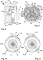
- the gearbox 40 can therefore be switched between four gears or gear positions S1, S2, S3 and S4, which are Figures 12, 13, 14 and 15 are shown.
- the gear is accommodated in a gear housing 44.
- the gear housing 44 has a peripheral wall 45 which delimits a substantially cylindrical interior in which the gear components, pinions and the like of the gear 40 are substantially accommodated.
- the front side of the gear housing 44 is covered by end walls 46, 47, for example covers.
- the end walls 46, 47 have through-openings 48 through which the motor output 27 can be connected to the gear drive 41 and the tool shaft 28 or the receiving chuck 32 can be connected to the gear output 42 of the gear 40.
- the through-openings 48 are, for example, push-through openings.
- the gear housing 44 is accommodated in a rotationally fixed manner in the machine housing 11 of the hand-held power tool 10, for which purpose, for example, a toothing 49 and/or an anti-twist projection 49A are provided on the front wall 47, which faces the tool holder 29, and/or a peripheral contour 50 designed in the manner of an anti-twist device on the front wall 46, which faces the drive motor 17.
- the gear housing 44 (the peripheral wall 45), which forms a basic gear housing, as it were, and the end walls 46, 47 forming the cover essentially tightly house the gear components of the gear 40 explained below, for which sealing elements, in particular textile seals, plastic seals, O-rings, labyrinth seals, etc., can be provided.
- the transmission 40 has a first gear stage G1 and a second gear stage G2.
- the first gear stage G1 forms an input gear stage and can be driven by the transmission drive 41.
- the second gear stage G2 forms an output gear stage and drives the transmission output 42 of the transmission 40.
- the gear stages G1 and G2 are planetary gear stages. Overall, the gear 40 is designed as a planetary gear.
- the gear stage G1 comprises a sun gear 51, which is arranged on the drive gear or gear drive 41 or is integral with the gear drive 41.
- the sun gear 51 meshes with planet gears 52, which are rotatably mounted on a web or planet gear carrier 53.
- the planet gears 52 are rotatably mounted on axle elements 55 protruding in front of a carrier body 54.
- the planet gears 52 can be mounted directly on the axle elements 55 or, as in the exemplary embodiment, preferably by means of roller bearings 56, in particular ball bearings or needle bearings, which improves the rotatability or the mounting.
- the axle elements 55 protrude from the carrier body 54 on opposite sides, and on the other hand an output 57, which forms a sun gear 58 for the second gear stage G2.
- an output 57 which forms a sun gear 58 for the second gear stage G2.
- a toothing 59 is provided on a radial outer circumference of the planet gear carrier 53 or carrier body 54.
- the planetary gears 52 form a planetary gear set 60, to which a first ring gear 61 and a second ring gear 62 are assigned.
- the planet gears 52 are, so to speak, stepped planet gears.
- the planet gears 52 have rolling circumferences 63, 64 with different diameters, which are assigned to the first and second ring gears 61, 62 or mesh with them when a corresponding switching position of the transmission 40 is set.
- the ring gear 61 is rotatable in the gear housing 44, but is axially immovable.
- the ring gear 61 is sandwiched between the end wall 46 and the steps 65 of the planet gears 52.
- the ring gear 61 is supported, for example, with its opposite end faces, directly or indirectly on the end wall 46, and oppositely, on the other end face, on a step 65 provided between the rolling circumferences 63, 64.
- a bearing plate 66 is preferably provided, which can be rotated in the interior of the peripheral wall 45 or preferably rotationally fixed, as in Figure 4 indicated by corresponding outer peripheral contours or rotary form-fitting contours.
- the ring gear 61 can be held immovably with respect to a rotational axis D of the transmission output 42 of the transmission 40 by other measures, for example by ring contours engaging with a support body 61 described in more detail later.
- a ring projection can protrude radially outwards in front of the support body 61 and engage in an annular groove on the inner circumference of the ring gear 61.
- axle elements 55 are fixed to their free ends facing away from the carrier body 54. sides are supported on a support body 67.
- the support body 67 has receptacles 68 for at least one of the axle elements 55.
- support projections 69 are provided which, so to speak, delimit receiving chambers or receiving spaces for the planet gears 52. It is possible, but not absolutely necessary, for some of the axle elements 55, in particular axle elements 55 which do not carry planet gears, to engage in the support projections 69 in a form-fitting manner, for which the support projections 69 have, for example, receptacle 69A.
- the planet gears 52 are thus received in a sandwich-like manner between the planet gear carrier 53 and the support body 57 and are rotatably mounted on the planet gear carrier 53, namely its axle elements 55.
- the support body 67 and the carrier body 54 can also be made in one piece. Furthermore, the support body 67 represents an option, i.e. the carrier body 54 would also be sufficient to rotatably support the planet gears 52, so that the support body 67 is not present in this case.
- Anti-rotation projections 70 are provided on the radial outer circumference of the second ring gear 62 and engage in anti-rotation receptacles 71 of the gear housing 44.
- the anti-rotation projections 70 are designed, for example, in the form of sliding blocks, link followers or the like. They engage in the anti-rotation receptacles 71.
- the anti-rotation receptacles 71 are designed, for example, as longitudinal grooves 72 that run parallel to the adjusting axis SA.
- the anti-rotation receptacles 71 or longitudinal grooves 72 extend, for example, on the inside or on the inner circumference of the peripheral wall 45.
- the anti-rotation projections 70 and/or the anti-rotation receptacles 71 can have different cross-sectional contours, for example, have a wider or narrower shape in the circumferential direction. This is not important in detail in order to ensure the basic functionality, namely that the ring gear 62 is adjustable along the adjustment axis SA or parallel to the adjustment axis SA on the transmission housing 40 and/or relative to the planetary gear set 60.
- the second ring gear 62 In the switching position shown, namely the first switching position S1 and the third switching position S3, the second ring gear 62 is in a setting position P1 with respect to the setting axis SA, in which the second ring gear 62 holds the first ring gear 61 in a rotationally fixed manner in the gear housing 40, so that the planet gears 52 with their smaller rolling circumferences 63 mesh with an internal toothing 75 of the first ring gear 61 and roll on the internal toothing 75.
- the second ring gear 62 which is held in a rotationally fixed manner in the gear housing 64, has anti-rotation contours on its inner circumference for holding the first ring gear 61 in a rotationally fixed manner, which has corresponding complementary rotational form-fitting contours on its outer circumference.
- These rotary form-locking contours and complementary rotary form-locking contours are provided by an internal toothing 73 of the second ring gear 62 and an external toothing 74 of the first ring gear 61, which can mesh with one another in a form-fitting manner.
- the internal toothing 73 of the second ring gear 62 therefore has the function, on the one hand, of allowing the planetary gears 52 to roll on it, and, on the other hand, of holding the first ring gear 61 in a rotationally fixed manner with respect to the gear housing 44 and thus also the machine housing 11 of the hand-held machine tool 10.
- the first ring gear 61 is released with respect to rotation.
- the planetary gears 52 or the planetary gear set 60 can take the first ring gear 61 along in rotation and experience no or at most a slight resistance from the ring gear 61.
- the planetary gears 52 roll with their larger rolling circumferences 64 on the inner circumference, thus the internal toothing 73, of the second ring gear 62, which is responsible for the Figures 13 and 15 shown switching position, the second switching position S2 and the fourth switching position S4, of the transmission 40.
- the output 57 of the first gear stage G1 rotates in the second and fourth switching positions at a higher speed and a lower torque than in the first and third switching positions S1, S3.
- the gear stage G2 comprises planetary gears 76 of a planetary gear set 77, which are in engagement with the sun gear 58, i.e. the output 57 of the first gear stage G1, on the one hand, and with a third ring gear 78 on the other hand.
- the third ring gear 78 is accommodated in the gear housing 44 so as to be displaceable along an adjusting axis SB.
- the adjusting axis SA can be coaxial with the adjusting axis SB or parallel to it.
- the adjusting axes SA, SB are in the Figures 12 and 13 shown as an example.
- the adjustment axes SA, SB can also be coaxial or coincide, for example, with a rotation axis D of the gear 40 and/or the gear drive 41 and/or the gear output 42.
- the rotation axis D of the gear 40 is simultaneously the rotation axis of the drive motor 17, so that ultimately the gear 40, the drive motor 17 and the gear output 42 are coaxial.
- the tool holder 23 also rotates about the rotation axis D.
- the planet gears 76 are rotatably mounted on a planet gear carrier 79, i.e. a web.
- the planet gear carrier 79 has a carrier body 80, of which axle elements 81 on the one hand and the transmission output 42 on the other hand are arranged on opposite sides.
- the axle elements 81 protrude towards the sun gear 58, i.e. the output 57 of the first gear stage G1, so that the planet gears 76 rotatably mounted on the axle elements 81 or rotatably mounted by the axle elements 81 are in engagement with the output 57 or can be driven by it.
- the planet gears 76 can be rotatably mounted directly on the axle elements 81 or indirectly, for example via rolling bearings (not shown), in particular needle bearings.
- the planetary gear set 77 comprises four planetary gears 76, while the planetary gear set 60 comprises three planetary gears 52.
- these numbers are not to be understood as limiting.
- a planetary gear set can also have two planetary gears, five planetary gears or a different number of planetary gears.
- the ring gear 78 has anti-twisting projections 83 on its radial outer circumference, which can be brought into engagement with anti-twisting receptacles 84 of the gear housing 44, for example on the cover or the front wall 47.
- the third ring gear 78 assumes a setting position P3 with respect to the setting axis SB, in which the third ring gear 78 is fixed in a rotationally fixed manner with respect to the rotation axis D or the transmission housing 44.
- the anti-rotation projections 83 then engage in the anti-rotation receptacles 84.
- the anti-rotation projections 83 of the third ring gear 78 are released from the anti-rotation receptacles 84 or are arranged apart from them, so that the ring gear 78 can rotate about the axis of rotation D.
- the planetary gears 78 roll with their outer circumferences on an internal toothing 85 of the ring gear 78.
- the second gear stage G2 thereby causes a speed reduction and thus an increase in torque from its input side to its output side or from its drive to the gear output 42.
- the gears 76 are still in engagement with the internal toothing 85.
- the ring gear 78 continues to be in engagement with the external or radially external toothing 59 of the planet gear carrier 53 with its internal toothing 85.
- the ring gear 78 is thus fixed in a rotationally fixed manner with respect to the planet gear carrier 73.
- the planet gears 76 are mounted in a rotationally fixed manner between the toothing of the sun gear 78 and the internal toothing 85 of the third ring gear 78.
- the transmission output 42 is provided on the planetary gear carrier 79.
- the planetary gear carrier 79 has support projections 86 protruding from the carrier body 80, between on which, for example, the tool shaft 28 can be arranged or by which the tool shaft 28 can be held.
- the tool shaft 28 is held by support elements 87, which in turn are supported on the support projections 86.
- the gear drive 41 which can also be referred to as a drive shaft, is attached to a pivot bearing 88, in particular a roller bearing, in the Figures 12 to 14 illustrated embodiment.
- the pivot bearing 88 is supported on an inner circumference of a passage opening of the support body 67 and is axially secured with respect to the axis of rotation D, for example by a snap ring 89.
- the support body 67 is rotatably mounted on the cover or the front wall 46 of the gear housing 44 using a pivot bearing 90.
- the pivot bearing 90 for example a ball bearing, needle bearing or other roller bearing (a plain bearing is also possible), is arranged and supported in the passage opening 48, for example.
- An actuating device 100 is used to switch and operate the transmission 40.
- the actuating device 100 can be used to adjust the ring gear 78 linearly between the setting positions P3, P4.
- the ring gear 78 forms a first switching transmission element 101.
- the ring gear 62 can also be adjusted linearly between the setting positions P1 and P2 by the actuating device 100 and is coupled to the actuating device 100 for this purpose.
- the ring gear 62 forms a second switching transmission element 102.
- a third switching transmission element 103 is not switched directly by the actuating device 100, but by the switching transmission element 102 which is, so to speak, interposed.
- the switching transmission element 103 is provided by the ring gear 78.
- the planetary gear set 60 forms a component of a first and a second gear arrangement 104, 105, see Figure 14 .
- the first gear arrangement 104 is associated with the first gearshift element 102 and comprises for example, the rolling circumferences 64 of the planetary gears 52.
- the second gear arrangement 105 is, so to speak, firmly coupled or connected to the first gear arrangement 104, at least in relation to the planetary gears 52.
- Each planetary gear 52 has different rolling circumferences 63, 64 and thus forms, so to speak, two partial planetary gears.
- the partial planetary gear with the rolling circumference 63 is assigned to the ring gear 61 and thus to the switching gear element 103 and the gear arrangement 105 as a gear 105A.
- the partial planetary gear with the rolling circumference 64 is assigned to the ring gear 62 and thus to the switching gear element 102 and the gear arrangement 104 as a gear 104A.
- the partial planetary gears are integrally or firmly coupled to one another due to the design as stepped planetary gears.
- the partial planetary gears can also be individual planetary gears that are connected to each other in a rotationally fixed manner or, in another embodiment, can be rotated relative to each other.
- the switching gear element 102 acts on the one hand as an active switching element in relation to the gear arrangement 104, namely in the setting position P2 it is directly in engagement with the larger rolling circumferences 64 of the planetary gears 52.
- the ring gear 62 is adjusted away from the planetary gears 52, i.e. the internal toothing 73 no longer meshes with the rolling circumferences 64.
- the ring gear 62 is a switching actuator for the other ring gear 61, which is held in a rotationally fixed manner by the ring gear 62 or the switching transmission element 102 with respect to the transmission housing 44 forming a transmission holding structure 44A by means of the intermeshing teeth, namely the external teeth 74 and thus an anti-twist contour 93 and the internal teeth 73 and thus a positive-locking counter-contour 94.
- the switching transmission element 103 is switched, so to speak, by the switching transmission element 102.
- the switching transmission element 102 can adjust the switching transmission element 103 only in the direction of a housing-fixed or stationary positive locking counter-contour 91, in particular on the front wall 46, so that an anti-twisting contour 92 of the switching transmission element 103 can adjust the positive locking counter-contour 91 into an engagement that holds the switching transmission element 103 in a rotationally secure manner with respect to the transmission support structure, i.e. the transmission housing 44 ( Figure 13 ).
- the anti-rotation contour 92 is, for example, a form-fitting projection running parallel to the adjusting axis SA
- the form-fitting counter-contour 91 is a corresponding form-fitting receptacle, for example a blind hole.
- gears as anti-rotation contours or form-fitting counter-contours are advantageous.
- actuating device 100 no direct coupling between the actuating device 100 and in particular its actuating member 110 and the switching gear element 103 is required in order to switch the gear arrangement 105.
- the structure of the actuating device 100 is therefore simpler.
- the gear 40 is shorter.
- the actuating device 100 is easy and convenient to handle, which will become clearer below.
- the actuating device 100 comprises the actuating member 110 with an actuating handle 111.
- the actuating handle 111 is arranged in an opening 33 on a top wall 34 of the housing 11 of the hand-held power tool 10 and is thus easily accessible for an operator.
- Numbers 1, 2, 3 and 4 or other markings 35 can be arranged on the housing 11, for example on the edge areas of the opening 33, which are assigned to the respective switching positions S1, S2, S3 and S4.
- the actuating handle 111 can be moved and/or pivoted within the opening 33.
- the actuating handle 111 can be adjusted to the area of a respective marking 35, in this case in the respective corner areas of the opening 33, in order to set the switching positions S1, S2, S3 and S4. Direct switching or setting of the actuating handle 111 from each of the switching positions S1, S2, S3 and S4 to any other of the switching positions S1, S2, S3 and S4 without setting an intermediate switching position is possible.
- the transmission 40 can be switched directly from the switching position S1 (operating handle 111 is in Figure 7 shown in dashed lines) to the switch position S4 (operating handle 111 is in Figure 7 shown in solid lines) without moving to one of the intermediate switching positions S2 or S3.
- the actuating handle 110 is provided on an upper side 114 of a particularly barrel-shaped or curved wall body 112, the underside 113 of which faces the gear housing 44.
- a curvature of the wall body 112 corresponds approximately to a curvature of the peripheral wall 45 of the gear housing 44, so that the wall body 112 is movable along the peripheral wall 45 in the manner of a cover or cover part or wall section.
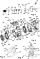
- the actuating member 110 is arranged on a driving ring 120, which in turn is mounted on the gear housing 44, in particular on the outer circumference of the peripheral wall 45, so as to be pivotable or rotatable about a pivot axis MA, which preferably coincides with the rotation axis D of the gear output 42.
- the actuating member 110 can pivot about the pivot axis MA and thus an actuating pivot axis BS between actuating positions D1 and D2.
- the driving ring 120 has an annular body 121 which is rotatably mounted in an annular guide 145 of the gear housing 44.
- the annular body 121 is guided on its narrow sides, for example, by circumferential projections 146 which protrude in front of the circumferential wall 45.
- a linear guide 123 for the actuating member 110 is provided at free longitudinal end regions 122 of the driving ring 120, so that the latter is movably mounted on the driving ring 120 along an actuating longitudinal axis BL between actuating positions L1 and L2.
- the linear guide 123 comprises linear guide sections 124 arranged directly on the longitudinal end regions 122, which are angularly spaced from one another according to the angular distance between the longitudinal end regions 122.
- the Actuating member 110 is, so to speak, a connecting member or link which connects the longitudinal end regions 122 of the driving ring 120 with one another.
- Linear guide projections 115 are provided on the underside 113 of the actuating member 110, which engage in the linear guide sections 124.
- the longitudinal end regions 122 of the driving ring 120 already have such a width or length in relation to the longitudinal actuation axis BL that they are in principle sufficient for linear guidance of the actuating member 110.
- the actuating member 110 can be guided in guide recesses, for example grooves, on the outer circumference, for example longitudinal sides and/or transverse sides, of the recess or opening 33 of the top wall 34.
- support projections 129 which protrude in front of the longitudinal end regions 122 of the driving ring 120 with respect to the longitudinal actuation axis BL or the rotation axis D.
- Additional linear guide sections 125 are provided on the support projections 122, into which the linear guide projections 115 engage and through which the linear guide projections 115 are guided with respect to the longitudinal actuation axis BL.
- the linear guide sections 124, 125 are, for example, longitudinal grooves whose transverse width with respect to the longitudinal actuation axis BL corresponds approximately to a transverse width of the linear guide projections 115.
- guide slots in the manner of the guide slots 133 explained below are provided on the longitudinal end regions 122 of the driving ring 120, with which a first coupling element 140, which in turn is connected to the switching transmission element 101 and thus to the ring gear 78, can be driven.
- the guide slots 133 are provided on a transmission member 130, which in turn can be rotated with respect to the actuating pivot axis BS or a rotation axis of the driving ring 120.
- the transmission member 130 has a ring body 131, on the longitudinal end regions 132 of which, for example, designed in the manner of plate bodies. Between the longitudinal end regions, an annular recess 137 is provided on the annular body 131, i.e. an intermediate space between annular sections 138 which extend between the longitudinal end regions 132.
- the transmission member 130 is arranged in an interior of the driving ring 120.
- a driver 136 protrudes from a radial outer circumference of the ring body 132 and is coupled in motion to a driver 126 of the driving ring 120.
- a fixed coupling would also be possible here.
- the driver 126 is mounted on the driving ring 120 so that it can be moved or pivoted.
- the driver 1126 is namely movably mounted in a slot 127 of the driving ring 120.
- the slot 127 extends in a ring on the driving ring 120. It is provided on the ring body 121.
- the driver 126 protrudes radially inward in front of the ring body 121 so that it can engage with the driver 136.
- a plug connection is provided between the drivers 126, 136.
- the link 127 is therefore arcuate or ring-shaped and extends around the pivot axis MA of the driving ring 120, around which the driving ring 120 pivots with respect to the gear housing 44.
- the driver 126 is spring-loaded by a spring arrangement 128, for example a helical spring.
- a spring arrangement 128, for example a helical spring is spring-loaded by the driver ring 120 and pivoted about the pivot axis MA.
- the driver 126 is moved along with it, so that, supported by the spring arrangement 128, this rotary movement or rotary force is transmitted to the transmission member 130, which ultimately converts the rotary movement into a linear movement for the coupling element 140 and the switching transmission element 101.
- the coupling element 140 is formed, for example, by a spring clip 141. Longitudinal ends 142 of the coupling element 140 protrude radially outward in front of a ring section of the coupling element 140 and engage in the guide slots 133 in the manner of slot followers.
- the guide slots 133 are, for example, inclined slots.
- a coupling element receptacle 143 for example an annular groove, is provided radially on the outside of the switching transmission element 101, into which the coupling element 140, in particular with the ring section 144.
- the resilient longitudinal ends 142 of the coupling element 140 also provide a certain spring property, so that the spring arrangement 128 could ultimately also be omitted.
- a recess 147 can be provided for the longitudinal end regions 132 of the transmission member 130, which represents a certain locking effect.
- the longitudinal ends 142 of the coupling element 140 which is arranged in the interior of the gear housing 44, protrude through recesses or longitudinal grooves 72 in front of the peripheral wall 45 and engage in the guide slots 133.
- the driving ring 120 also pivots at the same time about the pivot axis MA, wherein this pivoting movement is deflected by a deflection gear 135, which includes, among other things, the guide slots 133 and the coupling element 140 and in particular its longitudinal ends 142, into a linear actuating movement for the actuating element 101 between the actuating positions P3 and P4.
- the transmission of the linear movement of the transmission member 110 with respect to the longitudinal actuation axis BL could, in principle, be transmitted directly into a linear actuation movement of a second coupling element 150, which is arranged between the actuation member 110 and the switching gear element 102.
- the coupling element 150 is pivotally mounted about a pivot axis S, so that a linear adjustment of the actuation member 110 along the longitudinal actuation axis BL in one direction is redirected into a linear adjustment of the actuating gear element 102 in an opposite direction.
- the coupling element 150 comprises a spring clip 159.
- the coupling element 150 comprises an actuating section 151 which engages in a guide receptacle 116 on the underside 113 of the actuating member 110. Furthermore, the actuating section 151 is received in a recess 124A between the linear guide sections 124, 125 of the driving ring 120.
- the spring clip 159 or the coupling element 150 is pivotably mounted on the gear housing 44 about the pivot axis S.
- the pivot axis S is located between the actuating section 151 and driving projections 154 on free end areas of the coupling element 150.
- bearing receptacles 157 are formed on the coupling element 150, into which bearing pins 156 engage, which protrude radially outward in front of the gear housing 44 or the peripheral wall 45.
- the bearing receptacles 157 are located between actuating sections 152 and driving sections 153 of the coupling element 150.
- the actuating sections 152, 153 are, so to speak, lever arms that protrude from the pivot axis S.
- the driving projections 154 which are, for example, thin wire ends, engage in driving recesses 155 of the gearshift element 102, and thus of the ring gear 62.
- driving recesses 155 For example, holes or, as in the embodiment, grooves are provided as driving recesses 155.
- the second coupling element 150 extends in an arc around the gearshift element 102, but is only in contact with the gearshift element 102 in the area of the driving projections 154.
- the coupling element 140 is ring-shaped due to its ring section 144 and is in engagement with the gearshift element 101 over a greater length.
- the coupling element 150 is arranged outside the transmission housing 44. Its driving projections 154 reach radially inward with respect to the actuating pivot axis BS or the pivot axis MA in front of the driving sections 153 and penetrate recesses 158 on the transmission housing 44 or peripheral wall 45 so that they are in engagement with the driving recesses 155 of the ring gear 62 or the switching transmission element 102.
- the actuating device 100 can also be locked by a locking arrangement 160.
- the locking arrangement 160 comprises a locking member 161, which can engage in locking recesses 164 on the actuating member 110, for example on the underside 113 of the wall body 112.
- the locking member 161 is spring-loaded by a spring 162 into its locking position engaging in the locking recesses 164.
- the spring 162 and preferably also the locking member 161 are received and/or guided in a receptacle or on a receptacle 163 of the gear housing 44, for example a cylindrical receptacle.
- Each locking recess 164 is assigned to one of the switching positions S1, S2, S3 and S4 of the gear 40.
- the operator can bring the actuating member 110 into the actuating position associated with the respective switching positions S1 - S4 with respect to the actuating longitudinal axis BL and the actuating pivot axis BS, in which locking is expediently possible in each case.
- the actuating member 110 can, for example, be locked and/or positioned in the actuating positions L1, D1 for setting the switching position S1, in the actuating positions L2, D2 for setting the switching position S2, in the actuating positions L1, D2 for setting the switching position S3 and finally in the actuating positions D2, L2 for setting the switching position S4.
- the driving ring 120 follows the movement of the actuating member 110 about the actuating pivot axis BS.
- the spring arrangement 128 decouples the actuating movement from the actual adjusting movement.
- the driving sections 153 can be springy or yield in a springy manner with respect to the actuating sections 151 and/or 152. This is achieved on the one hand by the design of the coupling element 150 as a spring clip 159. In addition, however, it is also made easier or improved by the fact that the bearing receptacle 157 is formed by a winding of the spring clip 159, so that the driving sections 153 are springy relative to the driving actuating sections 152 with respect to the pivot axis S.
- the switching gear element 102 can also in principle serve to couple the gear wheel arrangements 104 and 105 to one another in a rotationally fixed manner.
- the switching gear element 102 in a setting position P2B is simultaneously in rotationally fixed engagement with both gear wheel arrangements 104 and 105 and can rotate within the gear support structure 44A or the gear housing 44.
- the switching gear element 102 forming the switching actuator is thus simultaneously in engagement with both gear wheel arrangements 104 and 105.
- an annular groove or similar other recess can be provided in the gear housing 44.
- the spring clip 159 or the coupling element 150 is pivotably mounted on the gear housing 44 about the pivot axis S, so that a respective sliding actuation of the actuating member 110 in a first direction is redirected into an opposite linear movement of the switching gear element 102.
- the coupling element 150 for example, to be firmly coupled to the actuating member 110, so that the aforementioned reversal of movement does not occur or, in other words, the directions of movement of the actuating member 110, the coupling element 150 and the switching gear element 102 run in the same direction.
- the same gear ratios are possible as in the configuration described above, if the gear 40 is configured as follows and in Figure 14 schematically indicated modified.
- the planet gears 52 are arranged on the planet gear carrier 53 in such a way that the smaller rolling circumference 63 is closer to the carrier body 54 than the larger rolling circumference 64.
- This is indicated by a planet gear 52B, which is arranged on the planet gear carrier 53 rotated by 180°, so to speak, like the planet gear 52.
- the adjustable with the linear adjustment of the ring gear 62 between the setting positions P1 and P2 are Gear ratios exactly the opposite of the embodiment described above.
Landscapes
- Engineering & Computer Science (AREA)
- Mechanical Engineering (AREA)
- General Engineering & Computer Science (AREA)
- Structure Of Transmissions (AREA)
- Transmission Devices (AREA)
- Gear-Shifting Mechanisms (AREA)
Claims (15)
- Machine-outil manuelle avec un moteur d'entraînement, un engrenage et un logement d'outil, dans laquelle une sortie de moteur du moteur d'entraînement est couplée en rotation à un entraînement d'engrenage de l'engrenage et une sortie d'engrenage, pouvant tourner autour d'un axe de rotation, de l'engrenage est couplée en rotation au logement d'outil, dans laquelle l'engrenage présente un premier élément l'engrenage de commutation (101) et un deuxième élément l'engrenage de commutation (102), qui peuvent être ajustés linéairement à l'aide d'un système d'actionnement (100) respectivement entre une première position de réglage et une deuxième position de réglage par rapport à un boîtier d'engrenage, dans laquelle le système d'actionnement (100) est couplé aux éléments l'engrenage de commutation et présente un organe d'actionnement (110) monté de manière à pouvoir pivoter autour d'un axe de pivotement d'actionnement par rapport à un boîtier de machine de la machine-outil manuelle et pouvant être actionné manuellement par un utilisateur de la machine-outil manuelle, dans laquelle le premier élément l'engrenage de commutation (101) peut être ajusté linéairement le long de son axe de réglage à l'aide d'un engrenage de renvoi (135) par un déplacement par pivotement de l'organe d'actionnement (110) autour de l'axe de pivotement d'actionnement, dans laquelle l'engrenage de renvoi (135) comprend un élément d'entraînement (120) s'étendant avec une forme annulaire autour du boîtier l'engrenage et monté de manière à pouvoir tourner autour de l'axe de pivotement d'actionnement, qui est couplé au premier élément l'engrenage de commutation (101) pour son ajustement linéaire à l'aide d'un premier élément de couplage (140), dans laquelle l'organe d'actionnement (110) est monté de manière à pouvoir coulisser linéairement le long d'un axe longitudinal d'actionnement sur l'élément d'entraînement (120) et est couplé à l'au moins un deuxième élément d'engrenage de commutation (102) à l'aide d'un deuxième élément de couplage (150) pour un coulissement linéaire du deuxième élément d'engrenage de commutation (102), caractérisée en ce que l'élément d'entraînement (120) est une bague d'entraînement (120), et qu'un organe de transmission (130) en particulier de forme annulaire pouvant être entraîné autour de l'axe de pivotement d'actionnement par la bague d'entraînement (120) est disposé entre la bague d'entraînement (120) et le premier élément de couplage (140), dans laquelle l'organe de transmission (130) et la bague d'entraînement (120) sont mobiles l'un par rapport à l'autre et un ensemble de ressort (128) pouvant être actionné par un déplacement relatif de l'organe de transmission (130) et de la bague d'entraînement (120) destiné à exposer le premier élément d'engrenage de réglage à l'action d'un ressort est disposé dans au moins une position de commutation.
- Machine-outil manuelle selon la revendication précédente,
caractérisée en ce qu'au moins un ensemble de ressort (128) est disposé entre l'organe d'actionnement (110) et le premier élément d'engrenage de commutation (101) et/ou le deuxième élément d'engrenage de commutation (102), dans laquelle il est prévu de manière avantageuse que l'ensemble de ressort est fourni, en particulier exclusivement, par le deuxième élément de couplage entre le deuxième élément d'engrenage de commutation (102) et l'organe d'actionnement (110). - Machine-outil selon l'une quelconque des revendications précédentes,
caractérisée en ce que le premier élément de couplage (140) et/ou le deuxième élément de couplage (150) sont ou comprennent un élément de ressort. - Machine-outil selon l'une quelconque des revendications précédentes, caractérisée en ce que le premier élément de couplage (140) et/ou le deuxième élément de couplage (150) sont un étrier de ressort (141, 159) ou comprennent un étrier de ressort (141, 159), dans laquelle l'étrier de ressort (141, 159) s'étend avec une forme annulaire autour du premier élément d'engrenage de commutation (101) ou du deuxième élément d'engrenage de commutation (102).
- Machine-outil manuelle selon l'une quelconque des revendications précédentes, caractérisée en ce que l'organe d'actionnement (110) est couplé au deuxième élément d'engrenage de commutation (102) exclusivement par le deuxième élément de couplage (150) et/ou par un unique composant.
- Machine-outil manuelle selon l'une quelconque des revendications précédentes, caractérisée en ce qu'est disposée, sur la bague d'entraînement (120) ou un organe de transmission (130) pouvant être entraîné autour de l'axe de pivotement d'actionnement par la bague d'entraînement (120), au moins une coulisse de guidage, avec laquelle le premier élément de couplage (140) vient en prise, pour renvoyer le déplacement de l'organe d'actionnement (110) autour de l'axe de pivotement d'actionnement en un déplacement linéaire du premier élément d'engrenage de réglage.
- Machine-outil manuelle selon l'une quelconque des revendications précédentes, caractérisée en ce que le deuxième élément de couplage (150) est monté de manière à pouvoir pivoter et/ou à pouvoir coulisser par rapport au boîtier d'engrenage.
- Machine-outil manuelle selon l'une quelconque des revendications précédentes, caractérisée en ce que le deuxième élément de couplage (150) est monté de manière à pouvoir pivoter sur un palier de pivotement prévu sur le boîtier d'engrenage, en particulier un tourillon de montage faisant saillie devant une paroi périphérique du boîtier d'engrenage ou dans un logement de montage prévu sur la paroi périphérique du boîtier de transmission, et/ou sur l'organe d'actionnement (110).
- Machine-outil manuelle selon l'une quelconque des revendications précédentes, caractérisée en ce que le deuxième élément de couplage (150) vient en prise avec un logement de guidage de l'organe d'actionnement (110) s'étendant en forme d'arc autour de l'axe de pivotement d'actionnement et/ou disposé à une distance autour de l'axe de pivotement d'actionnement.
- Machine-outil manuelle selon l'une quelconque des revendications précédentes, caractérisée en ce qu'elle présente un ensemble d'enclenchement (160) destiné à enclencher l'organe d'actionnement (110) dans au moins une position d'actionnement.
- Machine-outil manuelle selon l'une quelconque des revendications précédentes, caractérisée en ce que l'organe d'actionnement (110) est monté de manière à pouvoir coulisser linéairement sur un guidage linéaire (123) de la bague d'entraînement (120) et/ou un boîtier de machine de la machine-outil manuelle, dans laquelle il est prévu de manière avantageuse que le deuxième élément de couplage (150) est logé dans un évidement (124A) du guidage linéaire (123) et/ou que le guidage linéaire (123) présente au moins deux sections de guidage linéaire (123) disposées l'une par rapport à l'autre à une distance angulaire par rapport à l'axe de pivotement d'actionnement.
- Machine-outil manuelle selon l'une quelconque des revendications précédentes, caractérisée en ce que l'organe d'actionnement (110) présente au moins une section d'appui destinée au soutien sur le boîtier de transmission.
- Machine-outil manuelle selon l'une quelconque des revendications précédentes, caractérisée en ce que l'organe d'actionnement (110) présente une forme de paroi en forme d'arc ou en forme de tonneau et/ou l'organe d'actionnement (110) relie entre elles des zones d'extrémité longitudinale tenues à distance les unes par rapport aux autres de la bague d'entraînement (120).
- Machine-outil manuelle selon l'une quelconque des revendications précédentes, caractérisée en ce que la transmission est un engrenage planétaire, et/ou le premier et/ou le deuxième élément d'engrenage de réglage sont ou comprennent une couronne (61, 62, 78).
- Machine-outil manuelle selon l'une quelconque des revendications précédentes, caractérisée en ce que l'engrenage peut être commuté entre au moins deux positions de commutation (S1, S2, S3, S4), dans lesquelles des rapports de vitesse de rotation entre l'entraînement d'engrenage et la sortie d'engrenage sont différents les uns des autres, dans laquelle l'engrenage comprend un premier ensemble de roue d'engrenage (104) et au moins un deuxième ensemble de roue d'engrenage (105), qui présentent respectivement au moins une roue d'engrenage ainsi qu'un élément d'engrenage de commutation, dont un est l'activateur de commutation et l'autre est l'élément d'engrenage de commutation pouvant être commuté par l'activateur de commutation, dans laquelle dans les deux ensembles de roue d'engrenage (104, 105), l'au moins une roue d'engrenage peut rouler sur l'élément d'engrenage de commutation de l'ensemble de roue d'engrenage (104, 105) et/ou l'élément d'engrenage de commutation peut rouler sur l'au moins une roue d'engrenage de l'ensemble de roue d'engrenage (104, 105), et l'élément d'engrenage de commutation respectif est monté de manière ajustable spatialement entre au moins deux positions de réglage pour régler les positions de commutation (S1, S2, S3, S4) de l'engrenage sur la structure de maintien d'engrenage (44A) et/ou peut être ajusté entre une position immobile et une position mobile par rapport à la structure de maintien d'engrenage (44A), et que pour commuter l'engrenage entre au moins deux des positions de commutation (S1, S2, S3, S4), l'élément d'engrenage de commutation (102) du premier ensemble de roue d'engrenage (104) forme un activateur de commutation pour le deuxième ensemble de roue d'engrenage (105), qui peut être commuté entre une première position de réglage et au moins une deuxième position de réglage, dans lesquelles une mobilité de l'élément d'engrenage de commutation (103) du deuxième ensemble de roue d'engrenage (105) est différente par rapport à la structure de maintien d'engrenage et/ou l'activateur de commutation n'est pas en prise et est en prise avec l'au moins une roue d'engrenage (105A) du deuxième ensemble de roue d'engrenage (105).
Applications Claiming Priority (2)
| Application Number | Priority Date | Filing Date | Title |
|---|---|---|---|
| DE102017119808.3A DE102017119808A1 (de) | 2017-08-29 | 2017-08-29 | Hand-Werkzeugmaschine |
| PCT/EP2018/072959 WO2019042908A1 (fr) | 2017-08-29 | 2018-08-27 | Machine-outil portative |
Publications (2)
| Publication Number | Publication Date |
|---|---|
| EP3676054A1 EP3676054A1 (fr) | 2020-07-08 |
| EP3676054B1 true EP3676054B1 (fr) | 2025-03-05 |
Family
ID=63405218
Family Applications (1)
| Application Number | Title | Priority Date | Filing Date |
|---|---|---|---|
| EP18759936.0A Active EP3676054B1 (fr) | 2017-08-29 | 2018-08-27 | Machine-outil portative |
Country Status (5)
| Country | Link |
|---|---|
| US (1) | US11285595B2 (fr) |
| EP (1) | EP3676054B1 (fr) |
| CN (1) | CN111065490B (fr) |
| DE (1) | DE102017119808A1 (fr) |
| WO (1) | WO2019042908A1 (fr) |
Families Citing this family (13)
| Publication number | Priority date | Publication date | Assignee | Title |
|---|---|---|---|---|
| DE102017119808A1 (de) * | 2017-08-29 | 2019-02-28 | Festool Gmbh | Hand-Werkzeugmaschine |
| DE102018000885A1 (de) * | 2018-02-03 | 2019-08-08 | Kocher-Plastik Maschinenbau Gmbh | Vorrichtung |
| US11396078B2 (en) * | 2019-06-10 | 2022-07-26 | Makita Corporation | Grinder |
| EP3944939B1 (fr) * | 2020-07-31 | 2025-09-03 | Ledermann GmbH & Co. KG | Unité d'outils et système d'outils commutables pour une telle unité d'outils |
| DE102020210824A1 (de) * | 2020-08-27 | 2022-03-03 | Robert Bosch Gesellschaft mit beschränkter Haftung | Handwerkzeugmaschine mit einem schaltbaren Getriebe |
| US12194587B2 (en) | 2020-11-10 | 2025-01-14 | Snap-On Incorporated | Pneumatic tool with gear train |
| EP4059665A1 (fr) | 2020-12-21 | 2022-09-21 | Techtronic Cordless GP | Outil électrique doté d'un ensemble engrenage |
| JP2022158639A (ja) * | 2021-04-02 | 2022-10-17 | 株式会社マキタ | 電動工具 |
| DE202021103380U1 (de) * | 2021-06-23 | 2022-09-26 | Hazet-Werk Hermann Zerver Gmbh & Co. Kg | Drehmomentwerkzeug |
| JP7803743B2 (ja) * | 2022-02-28 | 2026-01-21 | 株式会社マキタ | 電動作業機 |
| EP4302926B1 (fr) | 2022-06-16 | 2025-08-06 | Milwaukee Electric Tool Corporation | Outil compact à percussion |
| DE102022212839A1 (de) * | 2022-11-30 | 2024-06-06 | Robert Bosch Gesellschaft mit beschränkter Haftung | Handwerkzeugmaschine |
| DE102022212835A1 (de) * | 2022-11-30 | 2024-06-06 | Robert Bosch Gesellschaft mit beschränkter Haftung | Handwerkzeugmaschine mit einem Distanzelement |
Family Cites Families (16)
| Publication number | Priority date | Publication date | Assignee | Title |
|---|---|---|---|---|
| DE10156392B4 (de) * | 2001-11-16 | 2008-04-10 | Robert Bosch Gmbh | Gangschaltvorrichtung für ein mehrstufiges Getriebe eines Elektrowerkzeugs |
| DE10222824A1 (de) * | 2002-05-21 | 2003-12-04 | Hilti Ag | Elektrowerkzeug mit mehrstufigem Getriebe |
| DE10315138A1 (de) * | 2003-04-03 | 2004-10-21 | Atlas Copco Electric Tools Gmbh | Schaltbares Getriebe einer handgeführten Werkzeugmaschine |
| US20060213675A1 (en) * | 2005-03-24 | 2006-09-28 | Whitmire Jason P | Combination drill |
| DE102006037191A1 (de) | 2006-08-09 | 2008-02-14 | Tts Tooltechnic Systems Ag & Co. Kg | Werkzeugmaschine mit mehrstufigem Planetengetriebe |
| US7762349B2 (en) * | 2007-11-21 | 2010-07-27 | Black & Decker Inc. | Multi-speed drill and transmission with low gear only clutch |
| DE102008056880A1 (de) * | 2008-11-12 | 2010-05-20 | Protool Gmbh | Handwerkzeugmaschine mit einem in einem Getriebegehäuse angeordneten schaltbaren Schaltgetriebe |
| DE102009060929A1 (de) * | 2009-12-23 | 2011-06-30 | C. & E. Fein GmbH, 73529 | Handwerkzeug |
| CN102753782B (zh) * | 2010-01-07 | 2015-09-30 | 布莱克和戴克公司 | 具有旋转输入控制的电动螺丝起子 |
| CN201989132U (zh) * | 2011-04-25 | 2011-09-28 | 广欣工业股份有限公司 | 多段变速机构 |
| EP2551063B1 (fr) | 2011-07-27 | 2014-04-02 | C. & E. Fein GmbH | Dispositif de commutation et machine-outil avec un dispositif de commutation |
| DE102013222550B4 (de) * | 2013-11-06 | 2024-12-19 | Robert Bosch Gmbh | Handwerkzeugmaschine |
| CN205001455U (zh) * | 2015-08-06 | 2016-01-27 | 群胜科技(苏州)有限公司 | 电动工具齿轮箱的变速装置 |
| EP3147077A1 (fr) * | 2015-09-22 | 2017-03-29 | HILTI Aktiengesellschaft | Machine-outil portative |
| DE102017119808A1 (de) * | 2017-08-29 | 2019-02-28 | Festool Gmbh | Hand-Werkzeugmaschine |
| TWM591461U (zh) * | 2019-04-16 | 2020-03-01 | 鑽全實業股份有限公司 | 可切換方向及調整動能的氣動工具 |
-
2017
- 2017-08-29 DE DE102017119808.3A patent/DE102017119808A1/de active Pending
-
2018
- 2018-08-27 EP EP18759936.0A patent/EP3676054B1/fr active Active
- 2018-08-27 US US16/642,241 patent/US11285595B2/en active Active
- 2018-08-27 CN CN201880056404.9A patent/CN111065490B/zh active Active
- 2018-08-27 WO PCT/EP2018/072959 patent/WO2019042908A1/fr not_active Ceased
Also Published As
| Publication number | Publication date |
|---|---|
| CN111065490B (zh) | 2023-11-03 |
| EP3676054A1 (fr) | 2020-07-08 |
| WO2019042908A1 (fr) | 2019-03-07 |
| US11285595B2 (en) | 2022-03-29 |
| CN111065490A (zh) | 2020-04-24 |
| DE102017119808A1 (de) | 2019-02-28 |
| US20200353610A1 (en) | 2020-11-12 |
Similar Documents
| Publication | Publication Date | Title |
|---|---|---|
| EP3676054B1 (fr) | Machine-outil portative | |
| EP3676053B1 (fr) | Machine-outil portative | |
| EP3676052B1 (fr) | Machine-outil portative | |
| EP2661336B1 (fr) | Transmission à trains épicycloïdaux pour une machine-outil | |
| EP1886769B1 (fr) | Machine-outil dotée d'un train épicycloïdal à plusieurs niveaux | |
| EP3003648A1 (fr) | Machine-outil portative équipée d'une transmission débrayable | |
| EP3317051B1 (fr) | Machine-outil portative | |
| DE102005056205A1 (de) | Bohrhammer mit drei Betriebsarten | |
| CH693405A5 (de) | Elektrohandwerkzeugmaschine. | |
| DE102010000795A1 (de) | Handgeführtes Elektrowerkzeug mit einem Planetengetriebe | |
| EP2618968A1 (fr) | Outil électrique à main présentant une boîte de vitesses | |
| DE102012213724B4 (de) | Planetengetriebe für eine Handwerkzeugmaschine | |
| EP2551063A1 (fr) | Dispositif de commutation et machine-outil avec un dispositif de commutation | |
| DE102010012024B4 (de) | Handwerkzeugmaschine mit einem Zwangsrotation-Exzentergetriebe | |
| DE102012212404A1 (de) | Handwerkzeugmaschinenvorrichtung | |
| EP2230052A2 (fr) | Machine-outil manuelle dotée d'une boîte de vitesse commutable agencée dans un boîtier de boîte de vitesse | |
| EP2095909A1 (fr) | Train épicycloïdal pour une machine-outil électrique et machine-outil portative électrique | |
| EP2185318A1 (fr) | Tourelle revolver | |
| EP2366496A1 (fr) | Machine-outil manuelle dotée d'une poignée | |
| EP2180979B1 (fr) | Outil à main électrique | |
| DE102006061600A1 (de) | Elektrohandwerkzeuggerät | |
| DE202008017689U1 (de) | Planetengetriebe für ein Elektrohandwerkzeuggerät sowie Elektrohandwerkzeuggerät |
Legal Events
| Date | Code | Title | Description |
|---|---|---|---|
| STAA | Information on the status of an ep patent application or granted ep patent |
Free format text: STATUS: UNKNOWN |
|
| STAA | Information on the status of an ep patent application or granted ep patent |
Free format text: STATUS: THE INTERNATIONAL PUBLICATION HAS BEEN MADE |
|
| PUAI | Public reference made under article 153(3) epc to a published international application that has entered the european phase |
Free format text: ORIGINAL CODE: 0009012 |
|
| STAA | Information on the status of an ep patent application or granted ep patent |
Free format text: STATUS: REQUEST FOR EXAMINATION WAS MADE |
|
| 17P | Request for examination filed |
Effective date: 20200304 |
|
| AK | Designated contracting states |
Kind code of ref document: A1 Designated state(s): AL AT BE BG CH CY CZ DE DK EE ES FI FR GB GR HR HU IE IS IT LI LT LU LV MC MK MT NL NO PL PT RO RS SE SI SK SM TR |
|
| AX | Request for extension of the european patent |
Extension state: BA ME |
|
| DAV | Request for validation of the european patent (deleted) | ||
| DAX | Request for extension of the european patent (deleted) | ||
| STAA | Information on the status of an ep patent application or granted ep patent |
Free format text: STATUS: EXAMINATION IS IN PROGRESS |
|
| 17Q | First examination report despatched |
Effective date: 20230904 |
|
| GRAP | Despatch of communication of intention to grant a patent |
Free format text: ORIGINAL CODE: EPIDOSNIGR1 |
|
| STAA | Information on the status of an ep patent application or granted ep patent |
Free format text: STATUS: GRANT OF PATENT IS INTENDED |
|
| INTG | Intention to grant announced |
Effective date: 20240711 |
|
| GRAJ | Information related to disapproval of communication of intention to grant by the applicant or resumption of examination proceedings by the epo deleted |
Free format text: ORIGINAL CODE: EPIDOSDIGR1 |
|
| GRAJ | Information related to disapproval of communication of intention to grant by the applicant or resumption of examination proceedings by the epo deleted |
Free format text: ORIGINAL CODE: EPIDOSDIGR1 |
|
| STAA | Information on the status of an ep patent application or granted ep patent |
Free format text: STATUS: EXAMINATION IS IN PROGRESS |
|
| GRAP | Despatch of communication of intention to grant a patent |
Free format text: ORIGINAL CODE: EPIDOSNIGR1 |
|
| STAA | Information on the status of an ep patent application or granted ep patent |
Free format text: STATUS: GRANT OF PATENT IS INTENDED |
|
| INTC | Intention to grant announced (deleted) | ||
| INTG | Intention to grant announced |
Effective date: 20241011 |
|
| GRAS | Grant fee paid |
Free format text: ORIGINAL CODE: EPIDOSNIGR3 |
|
| GRAA | (expected) grant |
Free format text: ORIGINAL CODE: 0009210 |
|
| STAA | Information on the status of an ep patent application or granted ep patent |
Free format text: STATUS: THE PATENT HAS BEEN GRANTED |
|
| P01 | Opt-out of the competence of the unified patent court (upc) registered |
Free format text: CASE NUMBER: APP_3527/2025 Effective date: 20250122 |
|
| AK | Designated contracting states |
Kind code of ref document: B1 Designated state(s): AL AT BE BG CH CY CZ DE DK EE ES FI FR GB GR HR HU IE IS IT LI LT LU LV MC MK MT NL NO PL PT RO RS SE SI SK SM TR |
|
| REG | Reference to a national code |
Ref country code: GB Ref legal event code: FG4D Free format text: NOT ENGLISH |
|
| REG | Reference to a national code |
Ref country code: CH Ref legal event code: EP |
|
| REG | Reference to a national code |
Ref country code: DE Ref legal event code: R096 Ref document number: 502018015625 Country of ref document: DE |
|
| REG | Reference to a national code |
Ref country code: IE Ref legal event code: FG4D Free format text: LANGUAGE OF EP DOCUMENT: GERMAN |
|
| PG25 | Lapsed in a contracting state [announced via postgrant information from national office to epo] |
Ref country code: RS Free format text: LAPSE BECAUSE OF FAILURE TO SUBMIT A TRANSLATION OF THE DESCRIPTION OR TO PAY THE FEE WITHIN THE PRESCRIBED TIME-LIMIT Effective date: 20250605 |
|
| PG25 | Lapsed in a contracting state [announced via postgrant information from national office to epo] |
Ref country code: FI Free format text: LAPSE BECAUSE OF FAILURE TO SUBMIT A TRANSLATION OF THE DESCRIPTION OR TO PAY THE FEE WITHIN THE PRESCRIBED TIME-LIMIT Effective date: 20250305 |
|
| REG | Reference to a national code |
Ref country code: NL Ref legal event code: MP Effective date: 20250305 |
|
| PG25 | Lapsed in a contracting state [announced via postgrant information from national office to epo] |
Ref country code: ES Free format text: LAPSE BECAUSE OF FAILURE TO SUBMIT A TRANSLATION OF THE DESCRIPTION OR TO PAY THE FEE WITHIN THE PRESCRIBED TIME-LIMIT Effective date: 20250305 |
|
| REG | Reference to a national code |
Ref country code: LT Ref legal event code: MG9D |
|
| PG25 | Lapsed in a contracting state [announced via postgrant information from national office to epo] |
Ref country code: NO Free format text: LAPSE BECAUSE OF FAILURE TO SUBMIT A TRANSLATION OF THE DESCRIPTION OR TO PAY THE FEE WITHIN THE PRESCRIBED TIME-LIMIT Effective date: 20250605 |
|
| PG25 | Lapsed in a contracting state [announced via postgrant information from national office to epo] |
Ref country code: HR Free format text: LAPSE BECAUSE OF FAILURE TO SUBMIT A TRANSLATION OF THE DESCRIPTION OR TO PAY THE FEE WITHIN THE PRESCRIBED TIME-LIMIT Effective date: 20250305 |
|
| PG25 | Lapsed in a contracting state [announced via postgrant information from national office to epo] |
Ref country code: LV Free format text: LAPSE BECAUSE OF FAILURE TO SUBMIT A TRANSLATION OF THE DESCRIPTION OR TO PAY THE FEE WITHIN THE PRESCRIBED TIME-LIMIT Effective date: 20250305 |
|
| PG25 | Lapsed in a contracting state [announced via postgrant information from national office to epo] |
Ref country code: GR Free format text: LAPSE BECAUSE OF FAILURE TO SUBMIT A TRANSLATION OF THE DESCRIPTION OR TO PAY THE FEE WITHIN THE PRESCRIBED TIME-LIMIT Effective date: 20250606 Ref country code: BG Free format text: LAPSE BECAUSE OF FAILURE TO SUBMIT A TRANSLATION OF THE DESCRIPTION OR TO PAY THE FEE WITHIN THE PRESCRIBED TIME-LIMIT Effective date: 20250305 |
|
| PG25 | Lapsed in a contracting state [announced via postgrant information from national office to epo] |
Ref country code: NL Free format text: LAPSE BECAUSE OF FAILURE TO SUBMIT A TRANSLATION OF THE DESCRIPTION OR TO PAY THE FEE WITHIN THE PRESCRIBED TIME-LIMIT Effective date: 20250305 |
|
| PG25 | Lapsed in a contracting state [announced via postgrant information from national office to epo] |
Ref country code: SE Free format text: LAPSE BECAUSE OF FAILURE TO SUBMIT A TRANSLATION OF THE DESCRIPTION OR TO PAY THE FEE WITHIN THE PRESCRIBED TIME-LIMIT Effective date: 20250305 |
|
| PG25 | Lapsed in a contracting state [announced via postgrant information from national office to epo] |
Ref country code: SM Free format text: LAPSE BECAUSE OF FAILURE TO SUBMIT A TRANSLATION OF THE DESCRIPTION OR TO PAY THE FEE WITHIN THE PRESCRIBED TIME-LIMIT Effective date: 20250305 |
|
| PG25 | Lapsed in a contracting state [announced via postgrant information from national office to epo] |
Ref country code: PT Free format text: LAPSE BECAUSE OF FAILURE TO SUBMIT A TRANSLATION OF THE DESCRIPTION OR TO PAY THE FEE WITHIN THE PRESCRIBED TIME-LIMIT Effective date: 20250707 |
|
| PGFP | Annual fee paid to national office [announced via postgrant information from national office to epo] |
Ref country code: DE Payment date: 20250707 Year of fee payment: 8 |
|
| PG25 | Lapsed in a contracting state [announced via postgrant information from national office to epo] |
Ref country code: IT Free format text: LAPSE BECAUSE OF FAILURE TO SUBMIT A TRANSLATION OF THE DESCRIPTION OR TO PAY THE FEE WITHIN THE PRESCRIBED TIME-LIMIT Effective date: 20250305 Ref country code: PL Free format text: LAPSE BECAUSE OF FAILURE TO SUBMIT A TRANSLATION OF THE DESCRIPTION OR TO PAY THE FEE WITHIN THE PRESCRIBED TIME-LIMIT Effective date: 20250305 |
|
| PGFP | Annual fee paid to national office [announced via postgrant information from national office to epo] |
Ref country code: GB Payment date: 20250704 Year of fee payment: 8 |
|
| PGFP | Annual fee paid to national office [announced via postgrant information from national office to epo] |
Ref country code: FR Payment date: 20250704 Year of fee payment: 8 |
|
| PG25 | Lapsed in a contracting state [announced via postgrant information from national office to epo] |
Ref country code: CZ Free format text: LAPSE BECAUSE OF FAILURE TO SUBMIT A TRANSLATION OF THE DESCRIPTION OR TO PAY THE FEE WITHIN THE PRESCRIBED TIME-LIMIT Effective date: 20250305 Ref country code: EE Free format text: LAPSE BECAUSE OF FAILURE TO SUBMIT A TRANSLATION OF THE DESCRIPTION OR TO PAY THE FEE WITHIN THE PRESCRIBED TIME-LIMIT Effective date: 20250305 |
|
| PG25 | Lapsed in a contracting state [announced via postgrant information from national office to epo] |
Ref country code: RO Free format text: LAPSE BECAUSE OF FAILURE TO SUBMIT A TRANSLATION OF THE DESCRIPTION OR TO PAY THE FEE WITHIN THE PRESCRIBED TIME-LIMIT Effective date: 20250305 |
|
| PG25 | Lapsed in a contracting state [announced via postgrant information from national office to epo] |
Ref country code: SK Free format text: LAPSE BECAUSE OF FAILURE TO SUBMIT A TRANSLATION OF THE DESCRIPTION OR TO PAY THE FEE WITHIN THE PRESCRIBED TIME-LIMIT Effective date: 20250305 |
|
| PG25 | Lapsed in a contracting state [announced via postgrant information from national office to epo] |
Ref country code: IS Free format text: LAPSE BECAUSE OF FAILURE TO SUBMIT A TRANSLATION OF THE DESCRIPTION OR TO PAY THE FEE WITHIN THE PRESCRIBED TIME-LIMIT Effective date: 20250705 |
|
| REG | Reference to a national code |
Ref country code: DE Ref legal event code: R097 Ref document number: 502018015625 Country of ref document: DE |
|
| PLBE | No opposition filed within time limit |
Free format text: ORIGINAL CODE: 0009261 |
|
| STAA | Information on the status of an ep patent application or granted ep patent |
Free format text: STATUS: NO OPPOSITION FILED WITHIN TIME LIMIT |
|
| PG25 | Lapsed in a contracting state [announced via postgrant information from national office to epo] |
Ref country code: DK Free format text: LAPSE BECAUSE OF FAILURE TO SUBMIT A TRANSLATION OF THE DESCRIPTION OR TO PAY THE FEE WITHIN THE PRESCRIBED TIME-LIMIT Effective date: 20250305 |
|
| REG | Reference to a national code |
Ref country code: CH Ref legal event code: L10 Free format text: ST27 STATUS EVENT CODE: U-0-0-L10-L00 (AS PROVIDED BY THE NATIONAL OFFICE) Effective date: 20260114 |
|
| 26N | No opposition filed |
Effective date: 20251208 |
|
| REG | Reference to a national code |
Ref country code: CH Ref legal event code: H13 Free format text: ST27 STATUS EVENT CODE: U-0-0-H10-H13 (AS PROVIDED BY THE NATIONAL OFFICE) Effective date: 20260324 |
|
| PG25 | Lapsed in a contracting state [announced via postgrant information from national office to epo] |
Ref country code: MC Free format text: LAPSE BECAUSE OF FAILURE TO SUBMIT A TRANSLATION OF THE DESCRIPTION OR TO PAY THE FEE WITHIN THE PRESCRIBED TIME-LIMIT Effective date: 20250305 |
|
| PG25 | Lapsed in a contracting state [announced via postgrant information from national office to epo] |
Ref country code: LU Free format text: LAPSE BECAUSE OF NON-PAYMENT OF DUE FEES Effective date: 20250827 |
|
| PG25 | Lapsed in a contracting state [announced via postgrant information from national office to epo] |
Ref country code: CH Free format text: LAPSE BECAUSE OF NON-PAYMENT OF DUE FEES Effective date: 20250831 |