EP3676062B1 - Dispositif mécanique à compliance passive pour la transmission de mouvement rotatif - Google Patents
Dispositif mécanique à compliance passive pour la transmission de mouvement rotatif Download PDFInfo
- Publication number
- EP3676062B1 EP3676062B1 EP18766150.9A EP18766150A EP3676062B1 EP 3676062 B1 EP3676062 B1 EP 3676062B1 EP 18766150 A EP18766150 A EP 18766150A EP 3676062 B1 EP3676062 B1 EP 3676062B1
- Authority
- EP
- European Patent Office
- Prior art keywords
- rotation
- assembly
- cam
- drive means
- main axis
- Prior art date
- Legal status (The legal status is an assumption and is not a legal conclusion. Google has not performed a legal analysis and makes no representation as to the accuracy of the status listed.)
- Active
Links
Images


Classifications
-
- B—PERFORMING OPERATIONS; TRANSPORTING
- B25—HAND TOOLS; PORTABLE POWER-DRIVEN TOOLS; MANIPULATORS
- B25J—MANIPULATORS; CHAMBERS PROVIDED WITH MANIPULATION DEVICES
- B25J17/00—Joints
- B25J17/02—Wrist joints
- B25J17/0208—Compliance devices
-
- B—PERFORMING OPERATIONS; TRANSPORTING
- B25—HAND TOOLS; PORTABLE POWER-DRIVEN TOOLS; MANIPULATORS
- B25J—MANIPULATORS; CHAMBERS PROVIDED WITH MANIPULATION DEVICES
- B25J19/00—Accessories fitted to manipulators, e.g. for monitoring, for viewing; Safety devices combined with or specially adapted for use in connection with manipulators
- B25J19/06—Safety devices
- B25J19/063—Safety devices working only upon contact with an outside object
-
- F—MECHANICAL ENGINEERING; LIGHTING; HEATING; WEAPONS; BLASTING
- F16—ENGINEERING ELEMENTS AND UNITS; GENERAL MEASURES FOR PRODUCING AND MAINTAINING EFFECTIVE FUNCTIONING OF MACHINES OR INSTALLATIONS; THERMAL INSULATION IN GENERAL
- F16D—COUPLINGS FOR TRANSMITTING ROTATION; CLUTCHES; BRAKES
- F16D3/00—Yielding couplings, i.e. with means permitting movement between the connected parts during the drive
- F16D3/50—Yielding couplings, i.e. with means permitting movement between the connected parts during the drive with the coupling parts connected by one or more intermediate members
- F16D3/60—Yielding couplings, i.e. with means permitting movement between the connected parts during the drive with the coupling parts connected by one or more intermediate members comprising pushing or pulling links attached to both parts
- F16D3/62—Yielding couplings, i.e. with means permitting movement between the connected parts during the drive with the coupling parts connected by one or more intermediate members comprising pushing or pulling links attached to both parts the links or their attachments being elastic
Definitions
- the invention relates to a mechanical device for transmitting movement between two segments of a robot.
- the field of the invention is the field of mechanical motion transmission devices, and more particularly the field of compliant motion transmission devices.
- Mechatronic systems especially robots, are manipulated by human operators and in an often cluttered environment. These systems are therefore subject to external forces or shocks. They must be compliant to guarantee the safety of the operators handling them and/or to avoid the deterioration of these systems.
- Active compliance solutions comprising force sensors and control means for adapting the response of these systems when they are subjected to forces greater than a safety threshold, which can be adjusted by the control means, are known.
- these systems have a slow response time due to the latency of the sensors and the control means.
- they must be continuously powered to operate.
- These systems have a high energy consumption.
- These systems also lack security and reliability in the event of a power cut or failure of the sensors used.
- Passive compliance solutions comprising motion transmission devices designed to deform for significant efforts. Some of these devices have increasing rigidity for increasing external forces. These devices lack safety because they quickly become rigid for significant efforts. Other devices become compliant when the external forces exceed the safety threshold intrinsic to the architecture of the device. These devices do not allow adjustment of the safety threshold and remain expensive because they must be resized for each desired safety threshold.
- An object of the present invention is to remedy these drawbacks.
- Another object of the present invention is to propose a device for transmitting movement with less expensive and less bulky compliant behavior.
- Another object of the present invention is to propose a motion transmission device with a more secure and more reliable compliant behavior.
- Another object of the present invention is to provide a motion transmission device with an easily customizable compliant behavior.
- the drive means being arranged between said assemblies and connected to one of the assemblies, the movement is transmitted from one segment to another by the drive means.
- said connecting interface being rotatable with respect to said sets, it allows the rotation of said sets between them.
- the connecting interface being elastically rotatable, allows the return of the device according to the invention to its initial state before an impact for example.
- the device according to the invention therefore exhibits a more reliable and more secure compliant behavior because it is not damaged during impact or significant efforts.
- the device comprises a reduced number of components, it is therefore less bulky and less expensive.
- the device according to the invention may comprise at least one elastically rotatable connecting interface on the side of a single assembly.
- the drive means can be arranged at a non-zero distance from the secondary axis so that the connection interface causes the rotation of said drive means when said device is subjected to a torque greater than a threshold, called of security.
- the safety threshold depends on the distance between the secondary axis and the drive means.
- the device according to the invention is therefore more easily customizable.
- the secondary axis can be arranged on the periphery of said assembly comprising the link interface.
- the device according to the invention may comprise at least one means for adjusting the position of the drive means with respect to the secondary axis so as to modify the safety threshold.
- the adjustment means therefore makes it possible to adjust the safety threshold beyond which the assemblies are driven in rotation with respect to each other.
- the device according to the invention is more easily customizable.
- the adjustment means makes it possible to adjust the level of security of the device according to the invention, for example according to the environment or the use of the robot. The device according to the invention is therefore more secure and more effective.
- the adjustment means can be arranged in the first set and/or in the second set.
- the adjustment means may comprise on the side of said connection interface an oblong opening in which the drive means is arranged.
- Said opening can be arranged in the direction connecting the secondary axis to the main axis.
- the oblong opening may have a width equal to the thickness of the drive means.
- the length of said opening can be between 10 mm and 50 mm.
- the assemblies can be integral.
- the adjustment means may comprise means for moving said drive means with respect to the secondary axis.
- a means can be a jack, an electric motor, etc.
- the adjustment means may comprise a sliding rail connected to said displacement means.
- the drive means can be arranged on said sliding rail.
- the device according to the invention may comprise means for holding said sliding rail.
- Said holding means may be a part comprising an oblong opening in which the drive means is arranged, or a guide support for said sliding rail, etc.
- the drive means may comprise two fingers, arranged symmetrical with respect to the main axis of rotation, said device comprising for at least one together two elastically rotatable connecting interfaces around two secondary axes symmetrical with respect to the main axis of rotation, each associated with one of said fingers.
- the use of two fingers allows a distribution of the forces on the two connection interfaces.
- the device according to the invention is thus more reliable.
- the device according to the invention may comprise, for each finger, a means for adjusting the position of said finger.
- Each adjustment means may comprise on the side of at least one, in particular each, connecting interface an oblong opening in which a finger is arranged.
- each adjustment means may comprise a sliding rail integral with a finger.
- the device according to the invention comprises, for at least one link interface, an elastic return mechanism, associated with said link interface, elastically opposing the rotation of said link interface.
- the device according to the invention comprises, on the side of the same assembly, two connection interfaces, cooperating with the same return mechanism.
- the device according to the invention is mechanically more robust. It is thus more reliable and more secure.
- the angle, called deflection, between the sets is, on the one hand, determined by the distance between the drive means.
- the angle of deflection varies according to the contact of the follower roller and the cam and therefore of the profile of the cam.
- the deflection angle increases with the torque up to the value of the safety threshold. For a torque greater than the safety threshold, the deflection angle continues to increase but the torque is limited to the safety threshold.
- the cam can be arranged in the first set or the second set.
- At least one, in particular each, cam follower can be arranged in the first set or the second set. At least one, in particular each, follower roller can be arranged free in translation with respect to said assembly.
- At least one, in particular each, cam follower may have a cylindrical or spherical shape.
- the cam may be in the form of an "8", its axis of rotation passing through the center of gravity of said cam and following the thickness of said cam.
- the cam with an "8" profile allows a small variation in the angle of deflection, between 0° and 2.5°, when the torque increases, but beyond the safety threshold, the variation in the angle of deflection is greater and can be between 2.5° and 25°.
- the cam can have a length between 30 mm and 90 mm, a width between 10 mm and 40 mm and a thickness between 2 mm and 15 mm.
- the profile of the cam can be symmetrical with respect to the main axis.
- the behavior of the device according to the invention is thus more uniform whatever its direction of rotation.
- the return mechanism may comprise two follower rollers arranged symmetrical with respect to the main axis of rotation.
- the two follower rollers allow a better distribution of the forces on the cam.
- the device according to the invention is thus more reliable and more secure.
- the cam can be connected to the connecting interface through a pinion integral with said cam, and meshing with a set of teeth provided on said connecting interface.
- a pinion and a toothed connection interface allows a reduction in torque.
- the speed reduction ratio of the pinion and of the connection interface depends on their teeth and can be between 5 and 9.
- the pinion can be arranged in the first set or the second set.
- At least one link interface may include internal or external toothing.
- the pinion can be arranged to rotate around the main axis.
- At least one connecting interface can take the form of a half-ring with internal teeth.
- the first assembly can be a cylindrical box, called the first box, rotating around the main axis, the said first box comprising two symmetrical drive means in the form of two fingers, each finger being arranged on a sliding rail connected to a cylinder provided to move said finger in the plane perpendicular to said main axis.
- the first box may comprise a fixed rail on which the sliding rails are arranged.
- the first box can have a diameter comprised between 50 mm and 150 mm and a height comprised between 15 mm and 50 mm.
- the first box can be made of any metal alloy, for example steel, or aluminum, or plastic.
- Each roller can be connected to two sliding parts. Said sliding pieces can be arranged below and above each roller.
- the second casing may comprise, for each sliding part, a guide rod arranged fixed in said second casing.
- Each sliding part can be connected to the second box by two springs.
- the second box can have a diameter comprised between 50 mm and 150 mm and a height comprised between 30 mm and 80 mm.
- the first and the second box can have the same diameter.
- the first set may comprise at least one bearing arranged in contact with the second set and provided to allow rotation between the first set and the second set.
- the first casing may comprise at least one bearing arranged in contact with the second casing and provided to allow rotation between the first casing and the second casing.
- the first casing may comprise two bearings, each bearing extending over a part of said first casing and in contact with the second casing.
- the device according to the invention can transmit a movement from the second segment to the first segment.
- the device according to the invention can transmit a movement from the first segment to the second segment.
- the first set, respectively the second set, can be connected to said first segment, respectively the second segment, by any fixing means, removable or not, such as by screwing, gluing, clamping, etc.
- the first segment and/or the second segment can be motorized.
- first and/or the second segment can comprise a geared motor.
- the first and/or the second set can be connected to said geared motor.
- At least one position sensor and/or at least one deformation sensor can be provided to measure the angle of deflection and/or a torque transmitted from one assembly to another assembly.
- a robot comprising at least one device according to the invention between two segments of said robot.
- the robot according to the invention can be any mechatronic machine comprising at least two segments, one of said segments driving the rotation of the other segment.
- the robot according to the invention can be in the form of a manipulator arm equipped or not or of a tool or of a functional head or of a tool holder.
- FIGURES 1a and 1b are schematic representations of the principle of operation of a non-limiting example of the device according to the invention.
- FIGURE la is a front view of a schematic representation of an example of the device according to the invention, while the FIGURE 1b is a top view of a schematic representation of the example of the FIGURE 1a .
- the device 100 comprises a first assembly 102 which can be connected to a first segment of a robot not represented on the FIGURE 1 .
- the device 100 also includes a second assembly 104 which can be connected to a second segment of a robot, not shown on the FIGURE 1 .
- the second assembly 104 can be connected to a geared motor fitted to said second segment.
- the first set 102 and second set 104 are designed to rotate around an axis of rotation 106, called the main axis.
- the first set 102 is also designed to rotate relative to the second set 104.
- the first set 102 comprises a so-called drive finger 108 connected to the first set 102 and arranged between the first set 102 and the second set 104.
- the second set 104 further comprises a connecting interface 110 that is elastically rotatable with respect to the second set 104 around a so-called secondary axis of rotation 112, fixed with respect to the second set 104.
- the secondary axis 112 is arranged on the periphery of said second set 104.
- the link interface 110 is associated with a return mechanism 114, designed to oppose elastically the rotation of the link interface 110.
- the drive finger 108 is arranged at a non-zero distance 116 from the secondary axis 112.
- the first set 102 is driven in rotation by the drive finger 108 by a torque T 1 depending on the input torque and the distance 116. If the torque T 1 is greater than the resistance torque T 2 of the return mechanism 114, the connection interface 110 causes the rotation of the drive pin 108 and therefore of the first set 102 with respect to the second set 104 in a direction opposite to the rotation of said second assembly 104.
- the variation of the distance 116 makes it possible to vary the torque T 1 and therefore to vary the value of the input torque, called the safety threshold, from which the drive finger 108 is driven in rotation.
- FIGURES 2a and 2b are schematic representations of a non-limiting example of an implemented callback mechanism of the device according to the invention.
- FIGURE 2a is a schematic representation of the recall mechanism at rest, while the FIGURE 2b is a schematic representation of the return mechanism of FIGURE la in deformation.
- the recall mechanism 200 of FIGURES 2a and 2b may be the return mechanism 114 of FIGURES 1a and 1b.
- the return mechanism 200 comprises a cam 202 rotating around an axis of rotation 203.
- the cam 202 has a profile in "8" symmetrical with respect to its axis of rotation 203.
- the return mechanism 200 further comprises two follower rollers 204 1 and 204 2 arranged free in translation by the connections 206 1 and 206 2 respectively.
- Each follower roller 204 1 and 204 2 is kept in contact with the cam 202 by a return spring 208 1 , 208 2 respectively.
- FIGURE 3 is a schematic representation of a non-limiting example of the behavior of the callback mechanism FIGURES 2a and 2b .
- the curve 300 represents the behavior of the cam 202 of the return mechanism 200 of the FIGURES 2a and 2b .
- the curve 300 represents the relationship between the return angle 210 of the cam 202 as a function of a torque 304 to which said return mechanism 200 is subjected.
- the return mechanism 200 therefore allows, on the one hand, a small variation in the return angle 210 when the torque 304 increases, and on the other hand, to limit the torque 304 to a maximum value 308.
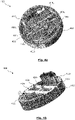
- FIGURES 4a and 4b are schematic representations of a non-limiting example of an assembly of the device according to the invention.
- FIGURES 4a and 4b are two different views of the assembly 400 which may be an assembly of the device 100 of FIGURES la and 1b.
- the assembly 400 is in the form of a box 402, called the first box, having a circular section intended to rotate around an axis of rotation corresponding to the axis of revolution of the said first box 402.
- the first box 402 can have a diameter of between 50 mm and 150 mm, in particular equal to 92 mm.
- the first box 402 can have a height comprised between 15 mm and 50 mm, in particular equal to 18 mm.
- the first box 402 comprising two identical fingers 404 1 and 404 2 arranged symmetrically with respect to the axis of rotation.
- the fingers 404 have a cylindrical shape, having a height between 5 mm and 15 mm.
- the finger 404 1 is arranged on a sliding rail 406 1 , respectively 406 2 .
- the rails 406 are symmetrical and mobile on a fixed rail 408 relative to the first box 402.
- the sliding rail 406 1 is connected to a jack 410 1 , respectively 410 2 , provided to cause the translation of said finger 404 1 , respectively 4042.
- the actuators 410 are arranged fixed in the first box 402 and can be controlled remotely wirelessly or by wire.
- the cylinders 410 can be connected to a control means.
- the cylinders 410 can move the fingers 404 over a distance between 10 mm and 50 mm.
- the first casing 402 further comprises two bearing cages 412 1 and 412 2 , called inner cages.
- Each inner cage 412 extends over part of the perimeter of said first casing 402.
- Each inner cage 412 may extend over a quarter of the perimeter of said first casing 402.
- the first box 402 further comprises a part 414 provided to hold the fingers 404.
- the part 414 comprises two rectangular openings symmetrical with respect to the axis of rotation. These openings are provided for the passage of fingers 404.
- Part 414 is fixed to said first box 402 by screwing.
- the first box 402 can be connected to a segment of a robot provided to receive a movement from another segment of the robot.
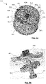
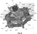
- FIGURES 5a, 5b and 5c are schematic representations of a non-limiting example of an assembly of the device according to the invention.
- the FIGURE 5a is a perspective view of assembly 500 which may be an assembly of device 100 of FIGURES 1a and 1b.
- the assembly 500 is in the form of a box 502, called the second box, having a circular cross-section provided to rotate around an axis of rotation, called the main axis, corresponding to the axis of revolution of the said second box 502.
- the second case 502 can have a diameter of between 50 mm and 150 mm, in particular equal to 92 mm.
- the second box 502 can have a height comprised between 30 mm and 80 mm, in particular equal to 59 mm.
- the second casing 502 comprises two bearing cages 504 1 and 504 2 , called outer cages.
- Each outer cage 504 extends over part of the perimeter of said first box 402.
- Each outer cage 504 can extend over approximately half the perimeter of said first box 502.
- the outer cages 504 are provided to cooperate with the inner cages 412 of the first box 402 of the FIGURES 4a and 4b .
- the second box 502 comprises two connection interfaces 506 1 and 506 2 arranged symmetrical with respect to the axis of rotation.
- the connection interface 506 1 is rotatable with respect to the second box 502 around an axis of rotation, called secondary, 505 1 , 505 2 respectively.
- the secondary axes 505 are arranged on the perimeter of the box 502 symmetrical with respect to the main axis of rotation.
- connection interface 506 1 comprises an oblong opening 507 1 , respectively 507 2 longitudinal in the direction passing through the secondary axes 505 and the main axis.
- the openings 507 are provided to receive the fingers 404 of the first box 402 of the FIGURES 4a and 4b .
- the fingers 404 can be arranged at a non-zero, and variable, distance from the secondary axes 505.
- Each link interface 506 further comprises a toothed part.
- the second box 502 further comprises a part 508 fixed relative to said second box 502 provided to maintain the connection interfaces 506.
- the part 508 includes the axes of rotation 505.
- the second box 502 also includes a pinion 510 arranged to rotate around the main axis and meshing with the teeth of the connection interfaces 506.
- the pinion 510 is connected, by clamping, to a shaft 512.
- the second box 502 further comprises a return mechanism provided to oppose the rotation of the connection interfaces 506 and comprising a cam 514 arranged on the shaft 512.
- the FIGURE 5b is a representation of cam 514.
- Cam 514 may be cam 202 of the FIGURE 2 .
- the cam 514 has a profile in the form of an "8" symmetrical with respect to the main axis of rotation.
- the cam 514 is assembled with the shaft 512 by clamping for example.
- the shaft 512 is maintained in rotation around the main axis, with a on the one hand by a bearing arranged in the part 508 and on the other hand by a bearing 516 arranged in the second box 502.
- the FIGURE 5c is a detailed representation of the elastic return mechanism.
- the return mechanism further comprises two follower rollers 518 1 and 518 2 in contact with the cam 514.
- the follower rollers 518 are arranged symmetrically with respect to the main axis.
- the follower roller 518 1 respectively 5182 , is held by two sliding parts 520 1a and 520 1b , respectively 5202a and 5202b.
- the sliding parts 520 1a and 520 2a are arranged above the follower rollers 518 and arranged movable along the rods 522 1a and 522 2a , respectively.
- the sliding parts 520 1a and 520 2a are connected to the second box 502 through the part 508, by two springs 524 1a symmetrical with respect to the rod 522 1a , and two springs 524 2a symmetrical with respect to the rod 522 2a .
- the sliding parts 520 1b and 520 2b are arranged below the follower rollers 518 and arranged movable along the rods 522 1b and 522 2b , respectively.
- the sliding parts 520 1b and 520 2b are connected to the second box 502 by two springs 524 1b and two springs 524 2b connected to a fixing part 526 arranged fixed in said second box 502.
- the FIGURE 6 is a schematic representation of examples of behavior of a device according to the invention comprising the sets of FIGURES 4 and 5 .
- the 600 1 -600 8 curves of the FIGURE 6 show examples of device behavior including sets 400 and 500 of FIGURES 4 and 5 .
- Each curve 600 represents a deflection angle 602 of said device as a function of a torque 604 applied to said device.
- Each curve 600 corresponds to a distance between the fingers 404 and the secondary axis of rotation 505, the curve 600 1 corresponding to the greatest distance and the curve 600 8 corresponding to the smallest distance.
- each curve 600 follows the profile of the cam rotation curve 514.
- the cam rotation curve may be the curve 300 of the FIGURE 3 .
- the curve 600 1 shows a slight variation in the angle of deflection 602 when the torque 604 increases. This variation is less than 2°.
- torque 604 exceeds a so-called safety threshold 606 1 , the variation in deflection angle 602 is greater and torque 606 is limited to safety threshold 606 1 .
- the safety threshold 606 increases when the distance decreases between the fingers 404 and the axis of rotation 505.
Landscapes
- Engineering & Computer Science (AREA)
- Mechanical Engineering (AREA)
- General Engineering & Computer Science (AREA)
- Robotics (AREA)
- Manipulator (AREA)
- Transmission Devices (AREA)
Description
- L'invention concerne un dispositif mécanique de transmission de mouvement entre deux segments d'un robot.
- Le domaine de l'invention est le domaine des dispositifs mécaniques de transmission de mouvement, et plus particulièrement le domaine des dispositifs compliants de transmission de mouvement.
- Les systèmes mécatroniques, en particulier les robots, sont manipulés par des opérateurs humains et dans un environnement souvent encombré. Ces systèmes sont donc soumis à des efforts externes ou des chocs. Ils doivent être compliants pour garantir la sécurité des opérateurs les manipulant et/ou pour éviter la détérioration de ces systèmes.
- On connait les solutions de compliance active comprenant des capteurs d'efforts et des moyens de commande pour adapter la réponse de ces systèmes lorsqu'ils sont soumis à des efforts supérieurs à un seuil de sécurité, qui peut être ajusté par les moyens de commande. Cependant, ces systèmes ont un temps de réponse lent dû à la latence des capteurs et des moyens de commande. De plus, ils doivent être alimentés en continu pour fonctionner. Ces systèmes présentent une consommation énergétique importante. Ces systèmes manquent aussi de sécurité et de fiabilité en cas de coupure d'énergie ou de défaillance des capteurs utilisés.
- On connait aussi les solutions de compliance passive comprenant des dispositifs de transmission de mouvement prévus pour se déformer pour des efforts importants. Certains de ces dispositifs présentent une rigidité croissante pour des efforts extérieurs croissants. Ces dispositifs manquent de sécurité car ils deviennent rapidement rigides pour des efforts importants. D'autres dispositifs deviennent compliants lorsque les efforts extérieurs dépassent le seuil de sécurité intrinsèque à l'architecture du dispositif. Ces dispositifs ne permettent pas le réglage du seuil de sécurité et restent coûteux car ils doivent être redimensionnés pour chaque seuil de sécurité désiré.
- Des exemples de solutions de compliance passive sont décrits dans les documents de brevet
WO 2012/038931 A1 etUS 2015/330458 A1 . - Un but de la présente invention est de remédier à ces inconvénients.
- Un autre but de la présente invention est de proposer un dispositif de transmission de mouvement avec un comportement compliant moins coûteux et moins encombrant.
- Un autre but de la présente invention est de proposer un dispositif de transmission de mouvement avec un comportement compliant plus sécurisé et plus fiable.
- Un autre but de la présente invention est de proposer un dispositif de transmission de mouvement avec un comportement compliant facilement personnalisable.
- Au moins un des objectifs précités est atteint par un dispositif mécanique selon la revendication 1 annexée permettant la transmission d'un mouvement de rotation autour d'un axe de rotation, dit principal, d'un premier segment à un deuxième segment d'un robot. Un tel dispositif comprend :
- un premier ensemble prévu pour être fixé audit premier segment,
- un deuxième ensemble prévu pour être fixé audit deuxième segment, et
- un moyen d'entrainement entre lesdits ensembles ;
- Avec le dispositif selon l'invention, le moyen d'entrainement étant agencé entre lesdits ensemble et relié à l'un des ensembles, le mouvement est transmis d'un segment vers un autre par le moyen d'entrainement. De plus, ladite interface de liaison étant rotative par rapport auxdits ensembles, elle permet la rotation desdits ensembles entre eux. Ainsi, en cas de choc ou d'effort important, lesdits ensembles sont entrainés en rotation l'un par rapport à l'autre. En outre, l'interface de liaison, étant élastiquement rotative, permet le retour du dispositif selon l'invention à son état initial avant un choc par exemple.
- Le dispositif selon l'invention présente donc un comportement compliant plus fiable, et plus sécurisé car il ne s'abime pas lors de choc ou d'efforts importants. De plus, le dispositif comprend un nombre réduit de composants, il est donc moins encombrant et moins coûteux.
- En outre, en ajustant l'élasticité de l'interface de liaison, il est possible de personnaliser facilement le dispositif selon l'invention.
- Le dispositif selon l'invention peut comprendre au moins une interface de liaison élastiquement rotative du côté d'un seul ensemble.
- Avantageusement, le moyen d'entrainement peut être agencé à une distance non nulle de l'axe secondaire de sorte que l'interface de liaison entraine la rotation dudit moyen d'entrainement lorsque ledit dispositif est soumis à un couple supérieur à un seuil, dit de sécurité.
- Le seuil de sécurité dépend de la distance entre l'axe secondaire et le moyen d'entrainement.
- Le dispositif selon l'invention est donc plus facilement personnalisable.
- En particulier, l'axe secondaire peut être agencé en périphérie dudit ensemble comprenant l'interface de liaison.
- Dans une version de réalisation préférée, le dispositif selon l'invention peut comprendre au moins un moyen d'ajustement de la position du moyen d'entrainement par rapport à l'axe secondaire de sorte à modifier le seuil de sécurité.
- Le moyen d'ajustement permet donc de régler le seuil de sécurité au-delà duquel les ensembles sont entrainés en rotation l'un par rapport à l'autre. Le dispositif selon l'invention est plus facilement personnalisable. De plus, le moyen d'ajustement permet de régler le niveau de sécurité du dispositif selon l'invention, par exemple en fonction de l'environnement ou de l'utilisation du robot. Le dispositif selon l'invention est donc plus sécurisé et plus efficace.
- Le moyen d'ajustement peut être agencé dans le premier ensemble et/ou dans le deuxième ensemble.
- Pour au moins une interface de liaison, le moyen d'ajustement peut comprendre du côté de ladite interface de liaison une ouverture oblongue dans laquelle le moyen d'entrainement est agencé.
- Ladite ouverture peut être agencée dans la direction reliant l'axe secondaire à l'axe principal.
- L'ouverture oblongue peut avoir une largeur égale à l'épaisseur du moyen d'entrainement. La longueur de ladite ouverture peut être comprise entre 10 mm et 50 mm.
- En particulier, lorsque le moyen d'entrainement est dans une position, dite d'arrêt, en butée dans l'ouverture oblongue du côté de l'axe principal, les ensembles peuvent être solidaires.
- En effet, lorsque le moyen d'entrainement est dans sa position d'arrêt, la rotation dudit moyen d'entrainement par l'interface de liaison n'est pas assurée. En conséquence, la rotation des ensembles entre eux n'est pas possible et le dispositif selon l'invention devient rigide.
- Préférentiellement, le moyen d'ajustement peut comprendre un moyen de déplacement dudit moyen d'entrainement par rapport à l'axe secondaire. Un tel moyen peut être un vérin, un moteur électrique, etc.
- Le moyen d'ajustement peut comprendre un rail coulissant relié audit moyen de déplacement. Le moyen d'entrainement peut être agencé sur ledit rail coulissant.
- Le dispositif selon l'invention peut comprendre un moyen de maintien dudit rail coulissant. Ledit moyen de maintien peut être une pièce comprenant une ouverture oblongue dans laquelle le moyen d'entrainement est agencé, ou un support de guidage dudit rail coulissant, etc.
- Dans une version privilégiée du dispositif selon l'invention, le moyen d'entrainement peut comprendre deux doigts, agencés symétriques par rapport à l'axe de rotation principal, ledit dispositif comprenant pour au moins un ensemble deux interfaces de liaison élastiquement rotatives autour de deux axes secondaires symétriques par rapport à l'axe de rotation principal, associées chacune à un desdits doigts.
- L'utilisation de deux doigts permet une répartition des efforts sur les deux interfaces de liaison. Le dispositif selon l'invention est ainsi plus fiable.
- En particulier, le dispositif selon l'invention peut comprendre, pour chaque doigt, un moyen d'ajustement de la position dudit doigt.
- Chaque moyen d'ajustement peut comprendre du côté d'au moins une, en particulier chaque, interface de liaison une ouverture oblongue dans laquelle un doigt est agencé.
- De plus, chaque moyen d'ajustement peut comprendre un rail coulissant solidaire avec un doigt.
- Le dispositif selon l'invention comprend, pour au moins une interface de liaison, un mécanisme de rappel élastique, associée à ladite interface de liaison, s'opposant élastiquement à la rotation de ladite interface de liaison.
- Le dispositif selon l'invention comprend, du côté d'un même ensemble, deux interfaces de liaison, coopérant avec un même mécanisme de rappel.
- Cet agencement permet une meilleure répartition des efforts. Le dispositif selon l'invention est plus robuste mécaniquement. Il est ainsi plus fiable et plus sécurisé.
- Dans un mode de réalisation avantageux du dispositif selon l'invention, un mécanisme de rappel peut comprendre :
- une came rotative, en particulier autour de l'axe de rotation principal ;
- au moins un galet suiveur en contact avec ladite came maintenu par au moins un ressort de rappel ;
- Lorsque les ensembles sont entrainés en rotation l'un par rapport à l'autre, l'angle, dit de déflexion, entre les ensembles est, d'une part, déterminé par la distance entre le moyen d'entrainement. D'autre part, l'angle de déflexion varie en fonction du contact du galet suiveur et de la came et donc du profil de la came.
- Lorsque le dispositif selon l'invention est soumis à un couple, l'angle de déflexion augmente avec le couple jusqu'à la valeur du seuil de sécurité. Pour un couple supérieur au seuil de sécurité, l'angle de déflexion continue d'augmenter mais le couple est limité au seuil de sécurité.
- La came peut être agencée dans le premier ensemble ou le deuxième ensemble.
- Au moins un, en particulier chaque, galet suiveur peut être agencé dans le premier ensemble ou le deuxième ensemble. Au moins un, en particulier chaque, galet suiveur peut être agencé libre en translation par rapport audit ensemble.
- Au moins un, en particulier chaque, galet suiveur peut avoir une forme cylindrique ou sphérique.
- Dans une version de réalisation particulière du dispositif selon l'invention, la came peut se présenter sous la forme de « 8 », son axe de rotation passant par le centre de gravité de ladite came et suivant l'épaisseur de ladite came.
- La came avec un profil en « 8 » permet une faible variation de l'angle de déflexion, comprise entre 0° et 2.5°, lorsque le couple augmente, mais au-delà du seuil de sécurité, la variation de l'angle de déflexion est plus importante et peut être comprise entre 2.5° et 25°.
- La came peut avoir une longueur comprise entre 30 mm et 90 mm, une largeur comprise entre 10 mm et 40 mm et une épaisseur comprise entre 2 mm et 15 mm.
- En particulier, le profil de la came peut être symétrique par rapport à l'axe principal. Le comportement du dispositif selon l'invention est ainsi plus uniforme quel que soit son sens de rotation.
- Dans une version préférée de réalisation du dispositif selon l'invention, le mécanisme de rappel peut comprendre deux galets suiveurs agencés symétriques par rapport à l'axe de rotation principal.
- Les deux galets suiveurs permettent une meilleure répartition des efforts sur la came. Le dispositif selon l'invention est ainsi plus fiable et plus sécurisé.
- Particulièrement, la came peut être reliée à l'interface de liaison au travers d'un pignon solidaire de ladite came, et en prise avec une denture prévue sur ladite interface de liaison.
- L'utilisation d'un pignon et d'une interface de liaison à denture permet une réduction en couple. En particulier le rapport de réduction en vitesse du pignon et de l'interface de liaison dépend de leurs dentures et peut être compris entre 5 et 9.
- Le pignon peut être agencé dans le premier ensemble ou le deuxième ensemble.
- Au moins une interface de liaison peut comprendre une denture interne ou externe.
- En particulier, le pignon peut être agencé rotatif autour de l'axe principal.
- Avantageusement, au moins une interface de liaison peut se présenter sous la forme d'une demi-couronne à denture interne.
- Dans un mode de réalisation préféré du dispositif selon l'invention, le premier ensemble peut être un boitier cylindrique, dit premier boitier, rotatif autour de l'axe principal, ledit premier boitier comprenant deux moyens d'entrainement symétriques se présentant sous la forme de deux doigts, chaque doigt étant agencé sur un rail coulissant relié à un vérin prévu pour déplacer ledit doigt dans le plan perpendiculaire audit axe principal.
- Le premier boitier peut comprendre un rail fixe sur lequel sont agencés les rails coulissants.
- Le premier boitier peut avoir un diamètre compris entre 50 mm et 150 mm et une hauteur comprise entre 15 mm et 50 mm.
- Le premier boitier peut être fabriqué en tout alliage métallique, par exemple en acier, ou en aluminium, ou en plastique.
- Dans un mode préféré de réalisation du dispositif selon l'invention, le deuxième ensemble peut être un boitier cylindrique, dit deuxième boitier, rotatif autour de l'axe principal, ledit deuxième boitier comprenant :
- deux interfaces de liaison, chaque interface de liaison se présentant sous la forme d'une demi-couronne à denture interne et comprenant une ouverture oblongue prévue pour recevoir un moyen d'entrainement,
- un pignon, rotatif autour de l'axe principal, en prise avec les dentures des demi-couronnes,
- une came se présentant sous la forme de « 8 » reliée par un arbre audit pignon, et
- deux galets suiveurs agencés symétriques et libres en translation dans ledit deuxième boitier et maintenus en contact avec la came par huit ressorts.
- Chaque galet peut être relié à deux pièces coulissantes. Lesdites pièces coulissantes peuvent être agencées en dessous et au-dessus de chaque galet.
- Le deuxième boitier peut comprendre, pour chaque pièce coulissante, une tige de guidage agencée fixe dans ledit deuxième boitier. Chaque pièce coulissante peut être reliée au deuxième boitier par deux ressorts.
- Le deuxième boitier peut avoir un diamètre compris entre 50 mm et 150 mm et une hauteur comprise entre 30 mm et 80 mm.
- Le premier et le deuxième boitier peuvent avoir le même diamètre.
- Préférentiellement, le premier ensemble peut comprendre au moins un roulement agencé en contact avec le deuxième ensemble et prévu pour permettre la rotation entre le premier ensemble et le deuxième ensemble.
- En particulier, le premier boitier peut comprendre au moins un roulement agencé en contact avec le deuxième boitier et prévu pour permettre la rotation entre le premier boitier et le deuxième boitier.
- Avantageusement, le premier boitier peut comprendre deux roulements, chaque roulement s'étendant sur une partie dudit premier boitier et en contact avec le deuxième boitier.
- Le dispositif selon l'invention peut transmettre un mouvement depuis le deuxième segment vers le premier segment.
- Alternativement, le dispositif selon l'invention peut transmettre un mouvement depuis le premier segment vers le deuxième segment.
- Le premier ensemble, respectivement le deuxième ensemble, peut être relié audit premier segment, respectivement le deuxième segment, par tout moyen de fixation, amovible ou non, tel que par vissage, collage, serrage, etc.
- Le premier segment et/ou le deuxième segment peuvent être motorisés.
- En particulier, le premier et/ou le deuxième segment peut comprendre un motoréducteur. Le premier et/ou le deuxième ensemble peut être relié audit motoréducteur.
- Dans une version particulière de réalisation, le dispositif selon l'invention peut comprendre :
- au moins un capteur de position prévu pour mesurer une rotation du premier ensemble par rapport au deuxième ensemble, et/ou
- au moins un capteur de déformation prévu pour mesurer un effort au niveau du premier ensemble et/ou du deuxième ensemble.
- En particulier, au moins un capteur de position et/ou au moins un capteur de déformation peuvent être prévus pour mesurer l'angle de déflexion et/ou un couple transmis d'un ensemble vers un autre ensemble.
- Selon un autre aspect de l'invention, il est proposé un robot comprenant au moins un dispositif selon l'invention entre deux segments dudit robot.
- Le robot selon l'invention peut être toute machine mécatronique comprenant au moins deux segments, l'un desdits segment entrainant la rotation de l'autre segment.
- Avantageusement, le robot selon l'invention peut se présenter sous la forme d'un bras manipulateur équipé ou non ou d'un outil ou d'une tête fonctionnelle ou d'un porte outil.
- D'autres avantages et caractéristiques apparaîtront à l'examen de la description détaillée d'exemples de réalisation nullement limitatifs, et des dessins annexés sur lesquels :
- les
FIGURES 1a et 1b sont des représentations schématiques du principe de fonctionnement d'un exemple non limitatif du dispositif selon l'invention, - les
FIGURES 2a et 2b sont des représentations schématiques d'un exemple non limitatif d'un mécanisme de rappel mis en œuvre du dispositif selon l'invention, - la
FIGURE 3 est une représentation schématique d'un exemple non limitatif de comportement du mécanisme de rappel desFIGURES 2a et 2b , - les
FIGURES 4a et 4b sont des représentations schématiques d'un exemple non limitatif d'un ensemble du dispositif selon l'invention, - les
FIGURES 5a, 5b et5c sont des représentations schématiques d'un exemple non limitatif d'un ensemble du dispositif selon l'invention ; et - la
FIGURE 6 est une représentation schématique d'exemples de comportement d'un dispositif selon l'invention comprenant les ensembles desFIGURES 4 et5 . - Il est bien entendu que les modes de réalisation qui seront décrits dans la suite ne sont nullement limitatifs. On pourra notamment imaginer des variantes de l'invention ne comprenant qu'une sélection de caractéristiques décrites par la suite isolées des autres caractéristiques décrites, si cette sélection de caractéristiques est suffisante pour conférer un avantage technique ou pour différencier l'invention par rapport à l'état de la technique antérieure. Cette sélection comprend au moins une caractéristique de préférence fonctionnelle sans détail structurel, ou avec seulement une partie des détails structurels si cette partie uniquement est suffisante pour conférer un avantage technique ou pour différencier l'invention par rapport à l'état de la technique antérieure.
- Les
FIGURES 1a et 1b sont des représentations schématiques du principe de fonctionnement d'un exemple non limitatif du dispositif selon l'invention. - La FIGURE la est une vue de face d'une représentation schématique d'un exemple du dispositif selon l'invention, tandis que la
FIGURE 1b est une vue de dessus d'une représentation schématique de l'exemple de laFIGURE 1a . - Le dispositif 100 comprend un premier ensemble 102 qui peut être relié à un premier segment d'un robot non représenté sur la
FIGURE 1 . Le dispositif 100 comprend aussi un deuxième ensemble 104 qui peut être relié à un deuxième segment d'un robot non représenté sur laFIGURE 1 . En particulier, le deuxième ensemble 104 peut être relié à un motoréducteur équipant ledit deuxième segment. - Les premier ensemble 102 et deuxième ensemble 104 sont prévus rotatifs autour d'un axe de rotation 106, dit principal. Le premier ensemble 102 est aussi prévu rotatif par rapport au deuxième ensemble 104.
- Le premier ensemble 102 comprend un doigt 108, dit d'entrainement, relié au premier ensemble 102 et agencé entre le premier ensemble 102 et le deuxième ensemble 104.
- Le deuxième ensemble 104 comprend en outre une interface de liaison 110 élastiquement rotative par rapport au deuxième ensemble 104 autour d'un axe de rotation 112, dit secondaire, fixe par rapport au deuxième ensemble 104. L'axe secondaire 112 est agencé en périphérie dudit deuxième ensemble 104.
- L'interface de liaison 110 est associée à un mécanisme de rappel 114, prévu pour s'opposer, de façon élastique, à la rotation de l'interface de liaison 110.
- Le doigt d'entrainement 108 est agencé à une distance 116 non nulle de l'axe secondaire 112.
- Lorsque le deuxième ensemble 104 est entrainé en rotation par un couple, dit d'entrée, le premier ensemble 102 est entrainé en rotation par le doigt d'entrainement 108 par un couple T1 dépendant du couple en entrée et de la distance 116. Si le couple T1 est supérieur au couple de résistance T2 du mécanisme de rappel 114, l'interface de liaison 110 entraine la rotation du doigt d'entrainement 108 et donc du premier ensemble 102 par rapport au deuxième ensemble 104 dans un sens contraire à la rotation dudit deuxième ensemble 104.
- La variation de la distance 116 permet de varier le couple T1 et donc de varier la valeur du couple d'entrée, dite seuil de sécurité, à partir de laquelle le doigt d'entrainement 108 est entrainé en rotation.
- Les
FIGURES 2a et 2b sont des représentations schématiques d'un exemple non limitatif d'un mécanisme de rappel mis en œuvre du dispositif selon l'invention. - La
FIGURE 2a est une représentation schématique du mécanisme de rappel au repos, tandis que laFIGURE 2b est une représentation schématique du mécanisme de rappel de la FIGURE la en déformation. - Le mécanisme de rappel 200 des
FIGURES 2a et 2b peut être le mécanisme de rappel 114 des FIGURES la et 1b. - Le mécanisme de rappel 200 comprend une came 202 rotative autour d'un axe de rotation 203. La came 202 présente un profil en « 8 » symétrique par rapport à son axe de rotation 203.
- Le mécanisme de rappel 200 comprend en outre deux galets suiveurs 2041 et 2042 agencés libre en translation par respectivement les liaisons 2061 et 2062.
- Chaque galet suiveur 2041 et 2042 est maintenu en contact avec la came 202 par un ressort de rappel 2081, respectivement 2082.
- Lorsque la came 202 est entrainée en rotation par un couple extérieur selon un angle 210, dit de rappel, le galet suiveur 2041, respectivement 2042, s'oppose à la rotation de ladite came 200 en suivant le profil de la came 200. Le profil de variation de l'angle de rappel 210 dépend donc du profil de la came 202.
- La
FIGURE 3 est une représentation schématique d'un exemple non limitatif de comportement du mécanisme de rappel desFIGURES 2a et 2b . - La courbe 300 représente le comportement de la came 202 du mécanisme de rappel 200 des
FIGURES 2a et 2b . - La courbe 300 représente la relation entre l'angle de rappel 210 de la came 202 en fonction d'un couple 304 auquel est soumis ledit mécanisme de rappel 200.
- Lorsque le couple 304 augmente, l'angle de rappel 210 augmente avec une variation comprise entre 0° et 2.5°, jusqu'à une valeur maximale du couple 308.
- Lorsque le couple 304 est supérieur à la valeur maximale 308, l'angle de rappel 302 continue d'augmenter mais le couple 304 est limité à une valeur maximale 308.
- Le mécanisme de rappel 200 permet donc, d'une part, une faible variation de l'angle de rappel 210 lorsque le couple 304 augmente, et d'autre part, de limiter le couple 304 à une valeur maximale 308.
- Les
FIGURES 4a et 4b sont des représentations schématiques d'un exemple non limitatif d'un ensemble du dispositif selon l'invention. - Les
FIGURES 4a et 4b sont deux vues différentes de l'ensemble 400 qui peut être un ensemble du dispositif 100 des FIGURES la et 1b. - L'ensemble 400 se présente sous la forme d'un boitier 402, dit premier boitier, ayant une section circulaire prévu rotatif autour d'un axe de rotation correspondant à l'axe de révolution dudit premier boitier 402. Le premier boitier 402 peut avoir un diamètre compris entre 50 mm et 150 mm, en particulier égal à 92 mm. Le premier boitier 402 peut avoir une hauteur comprise entre 15 mm et 50 mm, en particulier égale à 18 mm.
- Le premier boitier 402 comprenant deux doigts 4041 et 4042 identiques et agencés symétriques par rapport à l'axe de rotation. Les doigts 404 ont une forme cylindrique, ayant une hauteur comprise entre 5 mm et 15 mm.
- Le doigt 4041, respectivement 4042, est agencé sur un rail coulissant 4061, respectivement 4062. Les rails 406 sont symétriques et mobiles sur un rail fixe 408 par rapport au premier boitier 402.
- Le rail coulissant 4061, respectivement 4062, est relié à un vérin 4101, respectivement 4102, prévu pour entrainer la translation dudit doigt 4041, respectivement 4042.
- Les vérins 410 sont agencés fixes dans le premier boitier 402 et peuvent être pilotés à distance de façon sans fil ou filaire. Les vérins 410 peuvent être reliés à un moyen de commande. Les vérins 410 peuvent déplacer les doigts 404 sur une distance comprise entre 10 mm et 50 mm.
- Le premier boitier 402 comprend en outre deux cages 4121 et 4122, dites cages intérieures, de roulement. Chaque cage intérieure 412 s'étend sur une partie du périmètre dudit premier boitier 402. Chaque cage intérieure 412 peut s'étendre sur un quart du périmètre dudit premier boitier 402.
- Le premier boitier 402 comprend en outre une pièce 414 prévue pour maintenir les doigts 404. La pièce 414 comprend deux ouvertures rectangulaires symétriques par rapport à l'axe de rotation. Ces ouvertures sont prévues pour le passage des doigts 404. La pièce 414 est fixée audit premier boitier 402 par vissage.
- Le premier boitier 402 peut être relié à un segment d'un robot prévu pour recevoir un mouvement d'un autre segment du robot.
- Les
FIGURES 5a, 5b et5c sont des représentations schématiques d'un exemple non limitatif d'un ensemble du dispositif selon l'invention. - La
FIGURE 5a est une vue en perspective de l'ensemble 500 qui peut être un ensemble du dispositif 100 des FIGURES la et 1b. - L'ensemble 500 se présente sous la forme d'un boitier 502, dit deuxième boitier, ayant une section circulaire prévu rotatif autour d'un axe de rotation, dit principal, correspondant à l'axe de révolution dudit deuxième boitier 502. Le deuxième boitier 502 peut avoir un diamètre compris entre 50 mm et 150 mm, en particulier égal à 92 mm. Le deuxième boitier 502 peut avoir une hauteur comprise entre 30 mm et 80 mm, en particulier égale à 59 mm.
- Le deuxième boitier 502 comprend deux cages 5041 et 5042, dites cages extérieures, de roulement. Chaque cage extérieure 504 s'étend sur une partie du périmètre dudit premier boitier 402. Chaque cage extérieure 504 peut s'étendre sur environ la moitié du périmètre dudit premier boitier 502. Les cages extérieures 504 sont prévues pour coopérer avec les cages intérieures 412 du premier boitier 402 des
FIGURES 4a et 4b . - Le deuxième boitier 502 comprend deux interfaces de liaison 5061 et 5062 agencés symétriques par rapport à l'axe de rotation. L'interface de liaison 5061, respectivement 5062, est rotatif par rapport au deuxième boitier 502 autour d'un axe de rotation, dit secondaire, 5051, respectivement 5052. Les axes secondaires 505 sont agencés sur le périmètre du boitier 502 symétriques par rapport à l'axe de rotation principal.
- L'interface de liaison 5061, respectivement 5062, comprend une ouverture oblongue 5071, respectivement 5072 longitudinale dans la direction passant par les axes secondaires 505 et l'axe principal. Les ouvertures 507 sont prévues pour recevoir les doigts 404 du premier boitier 402 des
FIGURES 4a et 4b . Les doigts 404 peuvent être agencés à une distance non nulle, et variable, des axes secondaires 505. Chaque interface de liaison 506 comprend en outre une partie à denture. - Le deuxième boitier 502 comprend en outre une pièce 508 fixe par rapport audit deuxième boitier 502 prévue pour maintenir les interfaces de liaison 506. La pièce 508 comprend les axes de rotation 505.
- Le deuxième boitier 502 comprend aussi un pignon 510 agencé rotatif autour de l'axe principal et en prise avec les dentures des interfaces de liaison 506. Le pignon 510 est relié, par serrage, à un arbre 512.
- Le deuxième boitier 502 comprend en outre un mécanisme de rappel prévu pour s'opposer à la rotation des interfaces de liaison 506 et comprenant une came 514 agencée sur l'arbre 512.
- La
FIGURE 5b est une représentation de la came 514. - La came 514 peut être la came 202 de la
FIGURE 2 . La came 514 présente un profil sous la forme de « 8 » symétrique par rapport à l'axe de rotation principale. La came 514 est assemblée avec l'arbre 512 par serrage par exemple. L'arbre 512 est maintenu en rotation autour de l'axe principal, d'une part par un roulement agencé dans la pièce 508 et d'autre part par un roulement 516 agencé dans le deuxième boitier 502. - La
FIGURE 5c est une représentation détaillée du mécanisme de rappel élastique. - Le mécanisme de rappel comprend en outre deux galets suiveurs 5181 et 5182 en contact avec la came 514. Les galets suiveurs 518 sont agencés symétrique par rapport à l'axe principal. Le galet suiveur 5181, respectivement 5182, est maintenu par deux pièces coulissantes 5201a et 5201b, respectivement 5202a et 5202b.
- Les pièces coulissantes 5201a et 5202a sont agencés au-dessus des galets suiveurs 518 et agencées mobiles suivant les tiges 5221a et 5222a, respectivement. De plus, les pièces coulissantes 5201a et 5202a sont reliés au deuxième boitier 502 à travers la pièce 508, par deux ressorts 5241a symétriques par rapport à la tige 5221a, et deux ressorts 5242a symétriques par rapport à la tige 5222a.
- Les pièces coulissantes 5201b et 5202b sont agencés au-dessous des galets suiveurs 518 et agencées mobiles suivant les tiges 5221b et 5222b, respectivement. De plus, les pièces coulissantes 5201b et 5202b sont reliés au deuxième boitier 502 par deux ressorts 5241b et deux ressorts 5242b reliés à une pièce de fixation 526 agencée fixe dans ledit deuxième boitier 502.
- La
FIGURE 6 est une représentation schématique d'exemples de comportement d'un dispositif selon l'invention comprenant les ensembles desFIGURES 4 et5 . - Les courbes 6001-6008 de la
FIGURE 6 représentent des exemples comportement du dispositif comprenant les ensembles 400 et 500 desFIGURES 4 et5 . - Chaque courbe 600 représente un angle de déflexion 602 dudit dispositif en fonction d'un couple 604 appliqué audit dispositif. Chaque courbe 600 correspond à une distance entre les doigts 404 et l'axe de rotation secondaire 505, la courbe 6001 correspondant à la plus grande distance et la courbe 6008 correspondant à la plus petite distance.
- Le profil de chaque courbe 600 suit le profil de la courbe de rotation de la came 514. La courbe de rotation de la came peut être la courbe 300 de la
FIGURE 3 . - La courbe 6001 montre une faible variation de l'angle de déflexion 602 lorsque le couple 604 augmente. Cette variation est inférieure à 2°. Lorsque le couple 604 dépasse un seuil 6061, dit de sécurité, la variation de l'angle de déflexion 602 est plus importante et le couple 606 est limité au seuil de sécurité 6061.
- Le seuil de sécurité 606 augmente lorsque la distance diminue entre les doigts 404 et l'axe de rotation 505.
- Bien sûr, l'invention n'est pas limitée aux exemples qui viennent d'être décrits et de nombreux aménagements peuvent être apportés à ces exemples sans sortir du cadre de l'invention tel que défini par les revendications ci-jointes.
Claims (19)
- Dispositif (100) mécanique de transmission d'un mouvement de rotation autour d'un axe de rotation (106), dit principal, d'un premier segment à un deuxième segment d'un robot, ledit dispositif (100) comprenant :- un premier ensemble (102;400) prévu pour être fixé audit premier segment,- un deuxième ensemble (104;500) prévu pour être fixé audit deuxième segment,- un moyen d'entrainement (108;404) entre lesdits ensembles (102;400,104;500) ;dans lequel, du côté d'un desdits ensemble (104;500), ledit moyen d'entrainement (108;404) est relié audit ensemble (104;500) par une interface de liaison (110;506), élastiquement rotative autour d'un axe de rotation (112;505), dit secondaire, fixe par rapport audit ensemble (104;500), autorisant une rotation dudit moyen d'entrainement (108;404) par rapport audit ensemble (104;500), caractérisé en ce que le dispositif comprend, du côté d'un même ensemble (102;400,104;500), deux interfaces de liaison (110;506), coopérant avec un même mécanisme de rappel (114,200) s'opposant élastiquement à la rotation de chaque interface de liaison (110;506).
- Dispositif (100) selon la revendication 1, dans lequel le moyen d'entrainement (108;404) est agencé à une distance (116) non nulle de l'axe secondaire (112;505) de sorte que l'interface de liaison (110;506) entraine la rotation dudit moyen d'entrainement (108;404) lorsque ledit dispositif (100) est soumis à un couple supérieur à un seuil, dit de sécurité.
- Dispositif (100) selon la revendication 2, comprenant au moins un moyen d'ajustement de la position du moyen d'entrainement (108;404) par rapport à l'axe secondaire (112;505) de sorte à modifier le seuil de sécurité.
- Dispositif (100) selon la revendication 3, dans lequel le moyen d'ajustement comprend du côté de l'interface de liaison (110;506) une ouverture oblongue (507) dans laquelle le moyen d'entrainement (108;404) est agencé.
- Dispositif selon la revendication 4, dans laquelle, lorsque le moyen d'entraînement (108;404) est dans une position, dite d'arrêt, en butée dans l'ouverture oblongue (507) du côté de l'axe de rotation principal (106), la rotation des ensembles (102;400, 104;500) entre eux n'est pas possible.
- Dispositif (100) selon l'une quelconque des revendications 1 à 5, dans lequel le moyen d'entrainement (108;404) comprend deux doigts, agencés symétriques par rapport à l'axe de rotation principal (106), et dans lequel les deux interfaces de liaison (110;506) sont élastiquement rotatives autour de deux axes secondaires (112;505) symétriques par rapport à l'axe de rotation principal (106), et associées chacune à un desdits doigts.
- Dispositif (100) selon la revendication 6 comprenant, pour chaque doigt, un moyen d'ajustement de la position dudit doigt.
- Dispositif (100) selon l'une quelconque des revendications 1 à 7, dans lequel le mécanisme de rappel (114,200) comprend :- une came (202;514) rotative, en particulier autour de l'axe de rotation principal (106) ;- au moins un galet suiveur (204,518) en contact avec ladite came (202;514) maintenu par au moins un ressort de rappel (524) ;de sorte que ladite came (202;514) déplace ledit galet suiveur (204,518) dans sa rotation.
- Dispositif (100) selon la revendication 8, dans lequel le profil de la came (202;514) est symétrique par rapport à l'axe de rotation principal (106).
- Dispositif (100) selon la revendication 8 ou 9, dans lequel la came (202;514) se présente sous la forme de « 8 », son axe de rotation passant par le centre de gravité de ladite came (202;514) et suivant l'épaisseur de ladite came (202;514).
- Dispositif (100) selon l'une quelconque des revendications 8 à 10, dans lequel le mécanisme de rappel (114,200) comprend deux galets suiveurs (204;518) agencés symétriques par rapport à l'axe de rotation de la came (202,514).
- Dispositif (100) selon l'une quelconque des revendications 8 à 11, dans lequel la came (202,514) est reliée à l'interface de liaison (110;506) au travers d'un pignon (510) solidaire de ladite came (202,514), et en prise avec une denture (510) prévue sur ladite interface de liaison (110;506).
- Dispositif (100) selon l'une quelconque des revendications 1 à 12, dans lequel l'interface de liaison (110;506) se présente sous la forme d'une demi-couronne à denture interne.
- Dispositif selon l'une quelconque des revendications 1 à 13, dans lequel le premier ensemble (400) est un boitier cylindrique, dit premier boitier, rotatif autour de l'axe principal, ledit premier boitier (400) comprenant deux moyens d'entrainement (404) symétriques se présentant sous la forme de deux doigts, chaque doigt étant agencé sur un rail coulissant (406) relié à un vérin (410) prévu pour déplacer ledit doigt dans le plan perpendiculaire audit axe principal.
- Dispositif selon l'une quelconque des revendications 1 à 14, dans lequel le deuxième ensemble (500) est un boitier cylindrique, dit deuxième boitier, rotatif autour de l'axe principal, ledit deuxième boitier (500) comprenant :- deux interfaces de liaison (506), chaque interface de liaison (506) se présentant sous la forme d'une demi-couronne à denture interne et comprenant une ouverture oblongue (507) prévue pour recevoir un moyen d'entrainement (108;404),- un pignon (510), rotatif autour de l'axe principal, en prise avec les dentures des demi-couronnes,- une came (514) se présentant sous la forme de « 8 » reliée par un arbre (512) audit pignon (510), et- deux galets suiveurs (518) agencés symétriques et libres en translation dans ledit deuxième boitier (500) et maintenus en contact avec la came (514) par huit ressorts (524).
- Dispositif (100) selon l'une quelconque des revendications 1 à 15, dans lequel le premier ensemble (102;400) comprend au moins un roulement (412) agencé en contact avec le deuxième ensemble (104;500) et prévu pour permettre la rotation entre le premier ensemble (102;400) et le deuxième ensemble (104;500).
- Dispositif (100) selon l'une quelconque des revendications 1 à 16, comprenant :- au moins un capteur de position prévu pour mesurer une rotation du premier ensemble (102;400) par rapport au deuxième ensemble (104;500), et/ou- au moins un capteur de déformation prévu pour mesurer un effort au niveau du premier ensemble (102;400) et/ou du deuxième ensemble (104;500).
- Robot comprenant au moins un dispositif (100) selon l'une quelconque des revendications 1 à 17 entre deux segments dudit robot.
- Robot selon la revendication 18, se présentant sous la forme d'un bras manipulateur équipé ou non d'un outil ou d'une tête fonctionnelle ou d'un porte outil.
Applications Claiming Priority (2)
| Application Number | Priority Date | Filing Date | Title |
|---|---|---|---|
| FR1758116A FR3070738B1 (fr) | 2017-09-01 | 2017-09-01 | Dispositif mecanique a compliance passive pour la transmission de mouvement rotatif |
| PCT/EP2018/073257 WO2019043068A1 (fr) | 2017-09-01 | 2018-08-29 | Dispositif mécanique à compliance passive pour la transmission de mouvement rotatif |
Publications (2)
| Publication Number | Publication Date |
|---|---|
| EP3676062A1 EP3676062A1 (fr) | 2020-07-08 |
| EP3676062B1 true EP3676062B1 (fr) | 2022-12-21 |
Family
ID=60202182
Family Applications (1)
| Application Number | Title | Priority Date | Filing Date |
|---|---|---|---|
| EP18766150.9A Active EP3676062B1 (fr) | 2017-09-01 | 2018-08-29 | Dispositif mécanique à compliance passive pour la transmission de mouvement rotatif |
Country Status (3)
| Country | Link |
|---|---|
| EP (1) | EP3676062B1 (fr) |
| FR (1) | FR3070738B1 (fr) |
| WO (1) | WO2019043068A1 (fr) |
Families Citing this family (2)
| Publication number | Priority date | Publication date | Assignee | Title |
|---|---|---|---|---|
| CN110002009B (zh) * | 2019-04-12 | 2020-08-14 | 北京控制工程研究所 | 一种被动柔顺组件及在轨补加接口装置 |
| CN110410474B (zh) * | 2019-08-28 | 2025-06-20 | 如冈自动化控制技术(上海)有限公司 | 一种凸轮式的开口转盘机构 |
Family Cites Families (4)
| Publication number | Priority date | Publication date | Assignee | Title |
|---|---|---|---|---|
| KR101195700B1 (ko) * | 2010-04-05 | 2012-10-29 | 고려대학교 산학협력단 | 가변 강성 액츄에이터 유닛 |
| IT1402194B1 (it) * | 2010-09-23 | 2013-08-28 | Fond Istituto Italiano Di Tecnologia | Giunto rotante a rigidezza regolabile. |
| TW201242732A (en) * | 2011-04-19 | 2012-11-01 | Prec Machinery Res & Dev Ct | Compliance mechanism |
| US9676104B2 (en) * | 2014-05-19 | 2017-06-13 | Yaskawa America, Inc. | Variable spring constant torque coupler |
-
2017
- 2017-09-01 FR FR1758116A patent/FR3070738B1/fr active Active
-
2018
- 2018-08-29 EP EP18766150.9A patent/EP3676062B1/fr active Active
- 2018-08-29 WO PCT/EP2018/073257 patent/WO2019043068A1/fr not_active Ceased
Also Published As
| Publication number | Publication date |
|---|---|
| EP3676062A1 (fr) | 2020-07-08 |
| FR3070738A1 (fr) | 2019-03-08 |
| WO2019043068A1 (fr) | 2019-03-07 |
| FR3070738B1 (fr) | 2020-02-07 |
Similar Documents
| Publication | Publication Date | Title |
|---|---|---|
| EP2061977B1 (fr) | Dispositif à friction pour le contrôle d'effort, et un amortisseur à friction comprenant un tel dispositif | |
| EP2858897B1 (fr) | Minimanche de pilotage d'un aeronef | |
| EP2463200B1 (fr) | Système de motorisation à couple adapté pour structures spatiales déployables | |
| WO2017032932A1 (fr) | Bras de robot articulé | |
| EP3994061B1 (fr) | Siège d'aéronef | |
| EP3676062B1 (fr) | Dispositif mécanique à compliance passive pour la transmission de mouvement rotatif | |
| EP2815151B1 (fr) | Butee d'amortissement pour articulation, notamment pour articulation de porte de vehicule | |
| EP3222456B1 (fr) | Dispositif de génération d'effort | |
| EP3460437A1 (fr) | Dispositif d'etalonnage dynamique de couple et/ou force | |
| WO2012150492A1 (fr) | Mécanisme de remontage automatique | |
| FR2960515A1 (fr) | Actionneur de commande de vol equipe de butees mecaniques | |
| EP1977934B1 (fr) | Butoir pour la protection d'un premier élément lors de la rencontre avec un deuxième élément | |
| EP2837557B1 (fr) | Dispositif de couplage d'une roue motorisée de train d'atterrissage d'aéronef | |
| EP3562741B1 (fr) | Dispositif d'entrainement | |
| EP1377863A1 (fr) | Dispositif de montage et de correction de la position d'un miroir s'etendant dans l'ombre du miroir et systeme optique equipe de ce dispositif | |
| FR2861154A1 (fr) | Ensemble de commande pour boite de vitesses robotisee. | |
| FR3041724A1 (fr) | Dispositif limiteur de couple | |
| EP2261588B1 (fr) | Dispositif de pointage en gisement d'une tourelle | |
| EP3670932B1 (fr) | Dispositif d'assemblage de type verrou par mecanisme de coins bidirectionnel | |
| WO2017207917A1 (fr) | Actionneur pour un embrayage, notamment de vehicule automobile | |
| FR3019880A1 (fr) | Organe de liaison a limitation de couple ; volet, actionneur et appareil de climatisation comportant un tel organe de liaison | |
| FR2821397A1 (fr) | Dispositif d'articulation et de commande en orientation pour volet aerodynamique | |
| CH714188B1 (fr) | Dispositif d'étalonnage dynamique de couple ou dispositif d'étalonnage dynamique de force | |
| EP3366520A1 (fr) | Porte-vélo | |
| FR2857074A1 (fr) | Dispositif de conversion d'un mouvement angulaire en mouvement lineaire |
Legal Events
| Date | Code | Title | Description |
|---|---|---|---|
| STAA | Information on the status of an ep patent application or granted ep patent |
Free format text: STATUS: UNKNOWN |
|
| STAA | Information on the status of an ep patent application or granted ep patent |
Free format text: STATUS: THE INTERNATIONAL PUBLICATION HAS BEEN MADE |
|
| PUAI | Public reference made under article 153(3) epc to a published international application that has entered the european phase |
Free format text: ORIGINAL CODE: 0009012 |
|
| STAA | Information on the status of an ep patent application or granted ep patent |
Free format text: STATUS: REQUEST FOR EXAMINATION WAS MADE |
|
| 17P | Request for examination filed |
Effective date: 20200330 |
|
| AK | Designated contracting states |
Kind code of ref document: A1 Designated state(s): AL AT BE BG CH CY CZ DE DK EE ES FI FR GB GR HR HU IE IS IT LI LT LU LV MC MK MT NL NO PL PT RO RS SE SI SK SM TR |
|
| AX | Request for extension of the european patent |
Extension state: BA ME |
|
| RIN1 | Information on inventor provided before grant (corrected) |
Inventor name: ZEGHLOUL, SAID Inventor name: LARIBI, MED AMINE Inventor name: ARSICAULT, MARC Inventor name: COURREGES, FABIEN Inventor name: AYOUBI, YOUNSSE |
|
| DAV | Request for validation of the european patent (deleted) | ||
| DAX | Request for extension of the european patent (deleted) | ||
| GRAP | Despatch of communication of intention to grant a patent |
Free format text: ORIGINAL CODE: EPIDOSNIGR1 |
|
| STAA | Information on the status of an ep patent application or granted ep patent |
Free format text: STATUS: GRANT OF PATENT IS INTENDED |
|
| RIC1 | Information provided on ipc code assigned before grant |
Ipc: F16D 3/62 20060101ALI20220704BHEP Ipc: F16D 3/50 20060101ALI20220704BHEP Ipc: B25J 19/06 20060101ALI20220704BHEP Ipc: B25J 17/02 20060101AFI20220704BHEP |
|
| INTG | Intention to grant announced |
Effective date: 20220720 |
|
| GRAS | Grant fee paid |
Free format text: ORIGINAL CODE: EPIDOSNIGR3 |
|
| GRAA | (expected) grant |
Free format text: ORIGINAL CODE: 0009210 |
|
| STAA | Information on the status of an ep patent application or granted ep patent |
Free format text: STATUS: THE PATENT HAS BEEN GRANTED |
|
| AK | Designated contracting states |
Kind code of ref document: B1 Designated state(s): AL AT BE BG CH CY CZ DE DK EE ES FI FR GB GR HR HU IE IS IT LI LT LU LV MC MK MT NL NO PL PT RO RS SE SI SK SM TR |
|
| REG | Reference to a national code |
Ref country code: GB Ref legal event code: FG4D Free format text: NOT ENGLISH |
|
| REG | Reference to a national code |
Ref country code: CH Ref legal event code: EP |
|
| REG | Reference to a national code |
Ref country code: DE Ref legal event code: R096 Ref document number: 602018044521 Country of ref document: DE |
|
| REG | Reference to a national code |
Ref country code: AT Ref legal event code: REF Ref document number: 1538766 Country of ref document: AT Kind code of ref document: T Effective date: 20230115 |
|
| REG | Reference to a national code |
Ref country code: IE Ref legal event code: FG4D Free format text: LANGUAGE OF EP DOCUMENT: FRENCH |
|
| REG | Reference to a national code |
Ref country code: LT Ref legal event code: MG9D |
|
| REG | Reference to a national code |
Ref country code: NL Ref legal event code: MP Effective date: 20221221 |
|
| PG25 | Lapsed in a contracting state [announced via postgrant information from national office to epo] |
Ref country code: SE Free format text: LAPSE BECAUSE OF FAILURE TO SUBMIT A TRANSLATION OF THE DESCRIPTION OR TO PAY THE FEE WITHIN THE PRESCRIBED TIME-LIMIT Effective date: 20221221 Ref country code: NO Free format text: LAPSE BECAUSE OF FAILURE TO SUBMIT A TRANSLATION OF THE DESCRIPTION OR TO PAY THE FEE WITHIN THE PRESCRIBED TIME-LIMIT Effective date: 20230321 Ref country code: LT Free format text: LAPSE BECAUSE OF FAILURE TO SUBMIT A TRANSLATION OF THE DESCRIPTION OR TO PAY THE FEE WITHIN THE PRESCRIBED TIME-LIMIT Effective date: 20221221 Ref country code: FI Free format text: LAPSE BECAUSE OF FAILURE TO SUBMIT A TRANSLATION OF THE DESCRIPTION OR TO PAY THE FEE WITHIN THE PRESCRIBED TIME-LIMIT Effective date: 20221221 |
|
| REG | Reference to a national code |
Ref country code: AT Ref legal event code: MK05 Ref document number: 1538766 Country of ref document: AT Kind code of ref document: T Effective date: 20221221 |
|
| PG25 | Lapsed in a contracting state [announced via postgrant information from national office to epo] |
Ref country code: RS Free format text: LAPSE BECAUSE OF FAILURE TO SUBMIT A TRANSLATION OF THE DESCRIPTION OR TO PAY THE FEE WITHIN THE PRESCRIBED TIME-LIMIT Effective date: 20221221 Ref country code: LV Free format text: LAPSE BECAUSE OF FAILURE TO SUBMIT A TRANSLATION OF THE DESCRIPTION OR TO PAY THE FEE WITHIN THE PRESCRIBED TIME-LIMIT Effective date: 20221221 Ref country code: HR Free format text: LAPSE BECAUSE OF FAILURE TO SUBMIT A TRANSLATION OF THE DESCRIPTION OR TO PAY THE FEE WITHIN THE PRESCRIBED TIME-LIMIT Effective date: 20221221 Ref country code: GR Free format text: LAPSE BECAUSE OF FAILURE TO SUBMIT A TRANSLATION OF THE DESCRIPTION OR TO PAY THE FEE WITHIN THE PRESCRIBED TIME-LIMIT Effective date: 20230322 |
|
| PG25 | Lapsed in a contracting state [announced via postgrant information from national office to epo] |
Ref country code: NL Free format text: LAPSE BECAUSE OF FAILURE TO SUBMIT A TRANSLATION OF THE DESCRIPTION OR TO PAY THE FEE WITHIN THE PRESCRIBED TIME-LIMIT Effective date: 20221221 |
|
| PG25 | Lapsed in a contracting state [announced via postgrant information from national office to epo] |
Ref country code: SM Free format text: LAPSE BECAUSE OF FAILURE TO SUBMIT A TRANSLATION OF THE DESCRIPTION OR TO PAY THE FEE WITHIN THE PRESCRIBED TIME-LIMIT Effective date: 20221221 Ref country code: RO Free format text: LAPSE BECAUSE OF FAILURE TO SUBMIT A TRANSLATION OF THE DESCRIPTION OR TO PAY THE FEE WITHIN THE PRESCRIBED TIME-LIMIT Effective date: 20221221 Ref country code: PT Free format text: LAPSE BECAUSE OF FAILURE TO SUBMIT A TRANSLATION OF THE DESCRIPTION OR TO PAY THE FEE WITHIN THE PRESCRIBED TIME-LIMIT Effective date: 20230421 Ref country code: ES Free format text: LAPSE BECAUSE OF FAILURE TO SUBMIT A TRANSLATION OF THE DESCRIPTION OR TO PAY THE FEE WITHIN THE PRESCRIBED TIME-LIMIT Effective date: 20221221 Ref country code: EE Free format text: LAPSE BECAUSE OF FAILURE TO SUBMIT A TRANSLATION OF THE DESCRIPTION OR TO PAY THE FEE WITHIN THE PRESCRIBED TIME-LIMIT Effective date: 20221221 Ref country code: CZ Free format text: LAPSE BECAUSE OF FAILURE TO SUBMIT A TRANSLATION OF THE DESCRIPTION OR TO PAY THE FEE WITHIN THE PRESCRIBED TIME-LIMIT Effective date: 20221221 Ref country code: AT Free format text: LAPSE BECAUSE OF FAILURE TO SUBMIT A TRANSLATION OF THE DESCRIPTION OR TO PAY THE FEE WITHIN THE PRESCRIBED TIME-LIMIT Effective date: 20221221 |
|
| PG25 | Lapsed in a contracting state [announced via postgrant information from national office to epo] |
Ref country code: SK Free format text: LAPSE BECAUSE OF FAILURE TO SUBMIT A TRANSLATION OF THE DESCRIPTION OR TO PAY THE FEE WITHIN THE PRESCRIBED TIME-LIMIT Effective date: 20221221 Ref country code: PL Free format text: LAPSE BECAUSE OF FAILURE TO SUBMIT A TRANSLATION OF THE DESCRIPTION OR TO PAY THE FEE WITHIN THE PRESCRIBED TIME-LIMIT Effective date: 20221221 Ref country code: IS Free format text: LAPSE BECAUSE OF FAILURE TO SUBMIT A TRANSLATION OF THE DESCRIPTION OR TO PAY THE FEE WITHIN THE PRESCRIBED TIME-LIMIT Effective date: 20230421 Ref country code: AL Free format text: LAPSE BECAUSE OF FAILURE TO SUBMIT A TRANSLATION OF THE DESCRIPTION OR TO PAY THE FEE WITHIN THE PRESCRIBED TIME-LIMIT Effective date: 20221221 |
|
| REG | Reference to a national code |
Ref country code: DE Ref legal event code: R097 Ref document number: 602018044521 Country of ref document: DE |
|
| PLBE | No opposition filed within time limit |
Free format text: ORIGINAL CODE: 0009261 |
|
| STAA | Information on the status of an ep patent application or granted ep patent |
Free format text: STATUS: NO OPPOSITION FILED WITHIN TIME LIMIT |
|
| PG25 | Lapsed in a contracting state [announced via postgrant information from national office to epo] |
Ref country code: DK Free format text: LAPSE BECAUSE OF FAILURE TO SUBMIT A TRANSLATION OF THE DESCRIPTION OR TO PAY THE FEE WITHIN THE PRESCRIBED TIME-LIMIT Effective date: 20221221 |
|
| 26N | No opposition filed |
Effective date: 20230922 |
|
| PG25 | Lapsed in a contracting state [announced via postgrant information from national office to epo] |
Ref country code: SI Free format text: LAPSE BECAUSE OF FAILURE TO SUBMIT A TRANSLATION OF THE DESCRIPTION OR TO PAY THE FEE WITHIN THE PRESCRIBED TIME-LIMIT Effective date: 20221221 |
|
| PG25 | Lapsed in a contracting state [announced via postgrant information from national office to epo] |
Ref country code: MC Free format text: LAPSE BECAUSE OF FAILURE TO SUBMIT A TRANSLATION OF THE DESCRIPTION OR TO PAY THE FEE WITHIN THE PRESCRIBED TIME-LIMIT Effective date: 20221221 |
|
| REG | Reference to a national code |
Ref country code: CH Ref legal event code: PL |
|
| PG25 | Lapsed in a contracting state [announced via postgrant information from national office to epo] |
Ref country code: MC Free format text: LAPSE BECAUSE OF FAILURE TO SUBMIT A TRANSLATION OF THE DESCRIPTION OR TO PAY THE FEE WITHIN THE PRESCRIBED TIME-LIMIT Effective date: 20221221 |
|
| PG25 | Lapsed in a contracting state [announced via postgrant information from national office to epo] |
Ref country code: LU Free format text: LAPSE BECAUSE OF NON-PAYMENT OF DUE FEES Effective date: 20230829 |
|
| PG25 | Lapsed in a contracting state [announced via postgrant information from national office to epo] |
Ref country code: LU Free format text: LAPSE BECAUSE OF NON-PAYMENT OF DUE FEES Effective date: 20230829 Ref country code: CH Free format text: LAPSE BECAUSE OF NON-PAYMENT OF DUE FEES Effective date: 20230831 |
|
| REG | Reference to a national code |
Ref country code: BE Ref legal event code: MM Effective date: 20230831 |
|
| REG | Reference to a national code |
Ref country code: IE Ref legal event code: MM4A |
|
| PG25 | Lapsed in a contracting state [announced via postgrant information from national office to epo] |
Ref country code: IT Free format text: LAPSE BECAUSE OF FAILURE TO SUBMIT A TRANSLATION OF THE DESCRIPTION OR TO PAY THE FEE WITHIN THE PRESCRIBED TIME-LIMIT Effective date: 20221221 |
|
| PG25 | Lapsed in a contracting state [announced via postgrant information from national office to epo] |
Ref country code: IE Free format text: LAPSE BECAUSE OF NON-PAYMENT OF DUE FEES Effective date: 20230829 |
|
| PG25 | Lapsed in a contracting state [announced via postgrant information from national office to epo] |
Ref country code: IE Free format text: LAPSE BECAUSE OF NON-PAYMENT OF DUE FEES Effective date: 20230829 |
|
| PG25 | Lapsed in a contracting state [announced via postgrant information from national office to epo] |
Ref country code: BE Free format text: LAPSE BECAUSE OF NON-PAYMENT OF DUE FEES Effective date: 20230831 |
|
| PG25 | Lapsed in a contracting state [announced via postgrant information from national office to epo] |
Ref country code: BG Free format text: LAPSE BECAUSE OF FAILURE TO SUBMIT A TRANSLATION OF THE DESCRIPTION OR TO PAY THE FEE WITHIN THE PRESCRIBED TIME-LIMIT Effective date: 20221221 |
|
| PG25 | Lapsed in a contracting state [announced via postgrant information from national office to epo] |
Ref country code: BG Free format text: LAPSE BECAUSE OF FAILURE TO SUBMIT A TRANSLATION OF THE DESCRIPTION OR TO PAY THE FEE WITHIN THE PRESCRIBED TIME-LIMIT Effective date: 20221221 |
|
| PG25 | Lapsed in a contracting state [announced via postgrant information from national office to epo] |
Ref country code: CY Free format text: LAPSE BECAUSE OF FAILURE TO SUBMIT A TRANSLATION OF THE DESCRIPTION OR TO PAY THE FEE WITHIN THE PRESCRIBED TIME-LIMIT; INVALID AB INITIO Effective date: 20180829 |
|
| PG25 | Lapsed in a contracting state [announced via postgrant information from national office to epo] |
Ref country code: HU Free format text: LAPSE BECAUSE OF FAILURE TO SUBMIT A TRANSLATION OF THE DESCRIPTION OR TO PAY THE FEE WITHIN THE PRESCRIBED TIME-LIMIT; INVALID AB INITIO Effective date: 20180829 |
|
| PGFP | Annual fee paid to national office [announced via postgrant information from national office to epo] |
Ref country code: DE Payment date: 20250929 Year of fee payment: 8 |
|
| PGFP | Annual fee paid to national office [announced via postgrant information from national office to epo] |
Ref country code: GB Payment date: 20250827 Year of fee payment: 8 |
|
| PGFP | Annual fee paid to national office [announced via postgrant information from national office to epo] |
Ref country code: FR Payment date: 20250827 Year of fee payment: 8 |
|
| PG25 | Lapsed in a contracting state [announced via postgrant information from national office to epo] |
Ref country code: TR Free format text: LAPSE BECAUSE OF FAILURE TO SUBMIT A TRANSLATION OF THE DESCRIPTION OR TO PAY THE FEE WITHIN THE PRESCRIBED TIME-LIMIT Effective date: 20221221 |