EP3676102B1 - Robotisches beschriftungsdrucksystem - Google Patents
Robotisches beschriftungsdrucksystem Download PDFInfo
- Publication number
- EP3676102B1 EP3676102B1 EP18852216.3A EP18852216A EP3676102B1 EP 3676102 B1 EP3676102 B1 EP 3676102B1 EP 18852216 A EP18852216 A EP 18852216A EP 3676102 B1 EP3676102 B1 EP 3676102B1
- Authority
- EP
- European Patent Office
- Prior art keywords
- printing module
- ink
- motion
- jet printing
- relative
- Prior art date
- Legal status (The legal status is an assumption and is not a legal conclusion. Google has not performed a legal analysis and makes no representation as to the accuracy of the status listed.)
- Active
Links
Images




Classifications
-
- B—PERFORMING OPERATIONS; TRANSPORTING
- B41—PRINTING; LINING MACHINES; TYPEWRITERS; STAMPS
- B41J—TYPEWRITERS; SELECTIVE PRINTING MECHANISMS, i.e. MECHANISMS PRINTING OTHERWISE THAN FROM A FORME; CORRECTION OF TYPOGRAPHICAL ERRORS
- B41J3/00—Typewriters or selective printing or marking mechanisms characterised by the purpose for which they are constructed
- B41J3/407—Typewriters or selective printing or marking mechanisms characterised by the purpose for which they are constructed for marking on special material
- B41J3/4073—Printing on three-dimensional objects not being in sheet or web form, e.g. spherical or cubic objects
-
- B—PERFORMING OPERATIONS; TRANSPORTING
- B25—HAND TOOLS; PORTABLE POWER-DRIVEN TOOLS; MANIPULATORS
- B25J—MANIPULATORS; CHAMBERS PROVIDED WITH MANIPULATION DEVICES
- B25J11/00—Manipulators not otherwise provided for
-
- B—PERFORMING OPERATIONS; TRANSPORTING
- B25—HAND TOOLS; PORTABLE POWER-DRIVEN TOOLS; MANIPULATORS
- B25J—MANIPULATORS; CHAMBERS PROVIDED WITH MANIPULATION DEVICES
- B25J13/00—Controls for manipulators
- B25J13/08—Controls for manipulators by means of sensing devices, e.g. viewing or touching devices
- B25J13/086—Proximity sensors
-
- B—PERFORMING OPERATIONS; TRANSPORTING
- B25—HAND TOOLS; PORTABLE POWER-DRIVEN TOOLS; MANIPULATORS
- B25J—MANIPULATORS; CHAMBERS PROVIDED WITH MANIPULATION DEVICES
- B25J13/00—Controls for manipulators
- B25J13/08—Controls for manipulators by means of sensing devices, e.g. viewing or touching devices
- B25J13/088—Controls for manipulators by means of sensing devices, e.g. viewing or touching devices with position, velocity or acceleration sensors
-
- B—PERFORMING OPERATIONS; TRANSPORTING
- B41—PRINTING; LINING MACHINES; TYPEWRITERS; STAMPS
- B41J—TYPEWRITERS; SELECTIVE PRINTING MECHANISMS, i.e. MECHANISMS PRINTING OTHERWISE THAN FROM A FORME; CORRECTION OF TYPOGRAPHICAL ERRORS
- B41J29/00—Details of, or accessories for, typewriters or selective printing mechanisms not otherwise provided for
- B41J29/38—Drives, motors, controls or automatic cut-off devices for the entire printing mechanism
-
- G—PHYSICS
- G05—CONTROLLING; REGULATING
- G05B—CONTROL OR REGULATING SYSTEMS IN GENERAL; FUNCTIONAL ELEMENTS OF SUCH SYSTEMS; MONITORING OR TESTING ARRANGEMENTS FOR SUCH SYSTEMS OR ELEMENTS
- G05B2219/00—Program-control systems
- G05B2219/30—Nc systems
- G05B2219/45—Nc applications
- G05B2219/45186—Print on workpieces
Definitions
- the present invention is a robotic printing system and method for directly applying livery designs on the surfaces of objects, especially on the various surfaces of aircraft bodies.
- a popular approach for livery painting involves multiple iterations of masking, spraying, and curing of a target surface, which require skillful personnel and could take several days to complete painting an aircraft.
- Robotic printing systems have been proposed for applying images directly on aircraft and other objects in order to improve the efficiency of livery painting.
- U.S. Pat. No. 7350890 issued to Baird et al. discloses a robotic printing system that can directly apply printing materials on a surface to create livery images.
- the system disclosed is comprised of an applicator for ejecting ink on a surface, a motivating device for carrying the applicator relative to the surface, and a controller for controlling the motion of the motivating device.
- the motivating device in this disclosure is a two-frame guiding system that provides motion of three or more degrees of freedom (DOF). This system is mostly suited for printing on near-flat surfaces such as aircraft vertical stabilizers due to the limited flexibility of the guiding mechanism.
- DOF degrees of freedom
- Patent No. 8545943 discloses a painting system for painting curved surfaces.
- the system disclosed consists of a paint material ejection device, a guiding device, and a control device, and the guide device is a semi-circular rail that can mechanically guide the ejection device along a curved surface. While this system is capable of printing on curved surfaces, it remains unclear how this guiding rail can be adjusted for different degrees of curvature.
- U.S. Patent Publication No. 9,266,353 discloses a robotic printing system that uses an articulated robot to carry an inkjet printer for livery printing. Because an articulated robot is capable of reaching the surface of objects of irregular shapes, this system provides increased flexibility for printing surfaces of various degrees of curvature.
- the main advantage of these robotic printing systems is the potential for more efficient livery printing compared to conventional approaches.
- a robotic printing system can directly apply printing materials on a surface to create an image. This eliminates the repetitive masking and spraying procedure and hence drastically improves the efficiency of livery printing.
- the aforementioned disclosures did not fully address a serious issue: the printing quality of such systems.
- An image printed by an inkjet printer is formed by a grid of ink droplets of different colours on a printing medium.
- ink droplets of the desired colour must be ejected at the desired location on the printing medium. This depends on two conditions. First, the relative motion between the printing medium and the inkjet head must be accurately controlled. Second, the nozzles in the inkjet head must be accurately triggered to eject print material droplets according to their motion relative to the printing medium.
- the motion platform moves the printing device by following pre-defined paths that were created by using a 3D model of a target object.
- the printing device's motion is susceptible to a variety of detrimental factors, such as mismatches between the 3D model and the real object, registration errors between the motion platform and the surface, and motion platform tracking errors between the planned and actual paths.
- the inadequate motion accuracy of these systems implies that they cannot precisely eject ink droplets at high spatial density, thus limiting the achievable resolution.
- the lack of accurate measurements of the relative motion also limits the accuracy and reliability of the triggering signals for inkjet heads. Due to these limitations, it may be a challenge for these systems to achieve consistently high-quality printing results.
- the aforementioned disclosures did not address the challenge of printing a single image seamlessly on a very large object. Since the work envelope of commercially available robotic systems cannot cover the entire surface of a very large object such as a passenger aircraft, a robotic printing system may need to move its base to multiple locations to expand its overall coverage. Therefore, the 3D representation of the image on the surface is divided into multiple swaths to facilitate more accurate printing whereby the robotic printing system prints one or more swaths from one location and then moves to another location corresponding to a location of a next swath(s) to be printed.
- adjacent swaths must be properly aligned in order to avoid gaps and overlaps. Aligning two adjacent swaths means that the current swath must be printed with respect to the previously printed swath. This requires detecting the location of a previously printed swath when printing the current swath. In addition, the motion of the printing device and the timing of ejection of the print material may need to be dynamically adjusted when printing the current swath. This swath alignment problem adds another level of complexity to the control of the motion platform and the printing device, which was not considered in the aforementioned disclosures.
- U.S. Patent Publication Number 9,527,275 discloses an inkjet printing system to address this swath alignment problem.
- the system disclosed simultaneously prints a coded pattern next to a swath that is currently being printed.
- the coded pattern then serves as a visual guiding cue for the printing system to print the next swath. While this scheme can reliably guide the printing device with respect to a previously printed swath, it requires a separate printing device in addition to the primary printing device.
- small alignment errors between two adjacent swaths may accumulate over the course of multiple swaths and may eventually lead to a noticeable distortion in the final image.
- United States Patent Publication No. US-A1-2014/0242285 discloses a system for applying paint to a target surface. It includes a dispensing system including a nozzle for dispensing paint, a trackable optical feature, a positioning device attached to the dispensing system for positioning the nozzle relative to the target surface, and a local camera for local referencing of the nozzle. The system further includes a external referencing device remotely located from the dispensing system for global referencing of the dispensing system using the trackable optical feature.
- the present disclosure provides a robotic printing system for printing images on the surface of an object.
- One exemplary system includes a printing module carried by a motion platform to directly eject printing materials on a surface.
- One aspect of this disclosure provides methods for accurately controlling the motion of the motion platform, generating accurate triggering signals for printing heads, and properly aligning adjacent swaths of an image.
- the present disclosure provides a method for printing a livery image on a surface of an object and for use in association with a motion platform, the method being as claimed in claim 1.
- the local sensing suite may comprise:
- the one or more relative motion sensors for measuring relative motion of the printing module with respect to the surface may comprise any of one or more wheel encoders travelling on the surface, one or more non-contact optical sensors estimating relative position or velocity, one or more non-contact capacitive sensors estimating relative motion, or a combination of thereof.
- Creating a first measurement product by fusing said acquired data from said local sensing suite and said one or more global motion tracking devices may comprise the steps of:
- Controlling a motion platform to move a printing module across a surface may comprise the steps of:
- the pre-planned path relative to the surface may be determined by the steps of:
- Dividing a livery image into a plurality of swaths may comprise:
- Dividing a livery image into a plurality of swaths may further comprise
- Printing a livery image may further comprise:
- Applying the printing material from the printing module to form the next printed swath may comprise applying the printing material to a plurality of regions in close proximity to the one or more boundaries of the first swath at a reduced intensity whereby the path of the next swath to be printed is shifted to allow for overlap between the first printed swath and the next printed swath.
- Determining the location for the next swath to be printed and aligning the next swath to be printed to a first printed swath may comprise the steps of:
- Determining a plurality of boundaries of a first printed swath may comprise:
- the present disclosure provides a system for applying a livery image to the surface of an object,the system being as claimed in claim 8.
- the local sensing suite may comprise:
- the printing module may further comprise one or more material curing devices including UV lamps for curing the plurality of adjacent swaths of the print material.
- the motion platform may comprise any one of a guiding frame, a multi-axis translation stage, a mobile vehicle, a multi-axis robotic manipulator, an actuating device, or a combination thereof.
- the motion platform may comprise the translation stage, the multi-axis robotic manipulator carried by said translation stage, and the actuating device mounted on an end effector of said multi-axis robotic manipulator.
- the actuating device may be decoupled from the translation stage and said multi-axis robotic manipulator carried by the translation stage, and the actuating device is controlled by a separate motion controller.
- the real-time processor may be a computer programmed with instructions to fuse a plurality of measurements from the local sensing suite and the global motion tracking devices to estimate the motion of the printing module relative to the surface.
- the real-time processor may be programmed with instructions to control the motion of the motion platform by receiving a pre-defined path and commanding the motion platform to follow the pre-defined path.
- the real-time processor may be programmed with instructions for computing a plurality of motion correcting commands for the motion platform to maintain a desired position, orientation, and velocity of the printing module relative to the surface.
- the computing a plurality of motion correcting commands for the motion platform to maintain a desired position, orientation, and velocity of the printing module relative to the surface may comprise the steps of:
- the real-time processor may be programmed with instructions for controlling the motion of the motion platform to align a plurality of adjacent swaths of a livery image.
- the controlling the motion of the motion platform to align a plurality of adjacent swaths of a livery image may comprise the steps of:
- the real-time processor may be programmed with instructions for generating a plurality of triggering signals for controlling the timing of applying printing material from the printing module to form a plurality of swaths of a livery image.
- the executive computer may be programmed with instructions to provide system management capabilities and a plurality of user interfaces.
- the executive computer may further comprise:
- the terms, “comprises” and “comprising” are to be construed as being inclusive and open ended, and not exclusive. Specifically, when used in this specification including claims, the terms, “comprises” and “comprising” and variations thereof mean the specified features, steps or components are included. These terms are not to be interpreted to exclude the presence of other features, steps or components.
- exemplary means “serving as an example, instance, or illustration,” and should not be construed as preferred or advantageous over other configurations disclosed herein.
- motion platform refers to a device that can carry a payload and can be controlled to move the payload in 3D space.
- Examples of motion platforms include guiding frames, robotic manipulators, multi-axis translation stages, unmanned ground vehicles, and any combinations of these above. It may also include actuating devices that can be controlled by a separate controller.
- the motion platform may be mounted on a mobile vehicle which can move it to different locations.
- work envelope or “reach envelope” refers to a 3D shape that defines the boundaries that a motion platform's end effector can reach with the platform's base fixed at one location.
- position and orientation refers to an object's coordinates with respect to a fixed point together with its alignment (or bearing) with respect to a fixed axis.
- position and orientation of a motion platform might be the coordinates of a point on the motion platform together with the bearing of the motion platform (e.g., in degrees).
- pose is used interchangeably as a short form for "position and orientation”.
- path refers to a sequence of poses (i.e., position and orientation) of the end effector with respect to the motion platform's base, the sequence of which defines an end effector trajectory of "path”.
- swath refers to a continuous portion of an image. It may also refer to the corresponding area of a surface, on which a swath of an image will be printed.
- tracking device refers to a device that measures up to the six degrees of freedom (position and orientation) of an object which is being tracked.
- registration refers to the process of finding the transformation between two coordinate frames associated with two objects.
- registering an object to the motion platform refers to the process of finding the transformation from a coordinate frame attached to the object to a coordinate frame attached to the motion platform's base.
- the present disclosure relates to a robotic printing system for printing livery images on a surface of an object.
- preferred embodiments of the invention will be disclosed, by way of example only, with reference to drawings. It should be understood that the invention can be embodied in many various and alternative forms. In other instances, well-known methods, procedures, and components have not been described in detail so as not to obscure the embodiments described herein. Also, the description is not to be considered as limiting the scope of the embodiments described herein.
- the robotic printing system as claimed provides a beneficial solution for creating high-resolution livery designs on the surface of 3D objects, especially on very large objects with irregular geometric shapes.
- the motion platform of this system enables a large and flexible workspace for printing on objects with various shapes and structures.
- Multiple local sensors in this system can directly measure the printing module's motion relative to the surface of the object being printed on.
- the motion feedback enables the printing system to achieve high motion accuracy for controlling the motion of the printing module relative to the target surface, which allows the system to print images on a 3D object at high resolution.
- the system uses one or more global motion tracking devices to measure the pose of various modules of the system in a global reference frame.
- the fusion of both local and global measurements reduces the drifting effect of local sensors, thus further improving the motion accuracy of the overall system. More importantly, this ensures the consistency of high motion accuracy of the system in a global reference frame even when the robotic printing system periodically moves its base to different locations. This allows the system to expand its overall work envelope by moving to multiple locations, thereby enabling it to print a high-resolution image seamless on a very large object.
- the aforementioned method can be applied to other large object surface operations which involve moving the actuating module along the object surface at a precise standoff distance, relative orientation and/or speed, in which high motion accuracy and coordination between the motion platform and actuating module with respect to the object's surface is necessary.
- Large object surface operations include surface cleaning, sanding, finishing, priming, coating and de-coating.
- printing should be understood as any of the aforementioned operations.
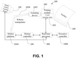
- the robotic livery printing system 100 shown in Figure 1 uses a motion platform 101 to carry a printing module 200 which applies printing materials for the application of livery patterns on a surface.
- the motion platform 101 consists of a multi-axis translation stage 101A, an articulated robot manipulator 101B, and an actuating device 101C.
- the printing module 200 is mounted on the actuating device 101C.
- a local sensing suite 250 is installed next to the printing module 200 for sensing the printing module's motion relative to the surface of the object 109.
- the global motion tracking device 105 is a device which measures the six DOF position and orientation of an object being tracked.
- the global motion tracking device 105 is a laserbased coordinate-measuring machine that measures a six DOF position and orientation of an object by tracking one or more reflective markers mounted on the object.
- An additional embodiment of a global motion tracking device is a multi-camera system which is capable of simultaneously tracking multiple objects, where each object carries a unique identification marker.
- the global motion tracking device 105 is used to measure a time-instant specific position and orientation of the base of the motion platform 101, the printing module 200, and the surface of the object 109 with respect to a global reference frame attached to the environment.
- a motion controller 106 is interfaced with the motion platform 101 for controlling the motion of the motion platform 101 relative to the surface 109 using feedback provided by the local sensing suite 250 and the global motion tracking device 105.
- the motion platform 101 may be any one of a guiding frame, a multi-axis translation stage, a mobile vehicle, a multi-axis robotic manipulator, an actuating device, or a combination of any of these modules.
- the motion platform 101 comprises an automated guided vehicle (AGV) and an industrial robotic manipulator which is carried by the AGV.
- AGV automated guided vehicle
- the motion of the AGV and the manipulator can be controlled in a coordinated or decoupled manner by a motion controller.
- the motion platform 101 comprises a multi-axis translation stage and an industrial robotic manipulator which is carried by the stage.
- the motion of the stage and the manipulator can be controlled in a coordinated or decoupled manner by a motion controller.
- the motion platform 101 may further include an actuating device mounted to an end effector of the robotic manipulator.
- the motion of the actuating device can be controlled in a decoupled manner at a different rate by a separate controller.
- the real-time processor 900 is a computer running a real-time operating system, said computer being interfaced with said printing module 200, said local sensing suite 250, said motion controller 106, and said global motion tracking device 105, and being programmed with instructions to process and fuse sensor measurements, control the motion of the motion platform 101, and manage the printing process of the printing module 200.
- the executive controller 1000 is a computer, programmed with instructions to provide a user interface and system management capabilities, said computer being interfaced with the real-time processor 900.
- the printing module 200 for applying printing materials is shown according to one embodiment of the invention.
- the local sensing suite 250 for sensing a surface 109 is also shown according to one embodiment of this disclosure.
- the printing module 200 comprises a plurality of printing heads 201 that are connected to a plurality of printing material tanks 206 for ejecting printing materials of one or more colors.
- the printing module 200 also includes an printing material tank levelling device 207, said printing material tank levelling device 207 being interfaced with the printing material tanks 206 and being configured to maintain the position and orientation of the printing material tanks 206 relative to the printing heads 201 within a predefined range.
- the printing module 200 may also include one or more ultraviolet (UV) light sources 205 positioned proximate to the printing heads 201 and operable to project UV radiation towards a surface 109 in order to accelerate polymerization of a UV curable ink.
- UV light sources 205 positioned proximate to the printing heads 201 and operable to project UV radiation towards a surface 109 in order to accelerate polymerization of a UV curable ink.
- the printing heads 201 are inkjet printing heads.
- the local sensing suite 250 generally comprises one or more relative motion sensors 252, one or more optical sensors 253, and one or more range sensors 254.
- the one or more relative motion sensors 252 are connected to the printing heads 201 for measuring the motion of the printing module 200 relative to a surface 109 and generating triggering signals that control the timing of ejection of the printing material from the printing heads 201.
- the printing material includes materials such as inks or paints.
- the one or more optical sensors 253 are coupled to the printing module 200 and operable to observe printed and unprinted areas of a surface 109.
- the one or more range sensors 254 are installed next to the printing module 200 and operable to scan the profile of a surface 109.
- the range sensors 254 are laser rangefinders that use lasers to measure distance.
- the measurement method includes methods such as time-of-flight, phase difference and triangulation.
- the relative motion sensors 252 may include any of one or more wheel encoders travelling on the surface, one or more non-contact optical sensors estimating relative motion, one or more non-contact (e.g., capacitive) sensors estimating relative motion, or a combination of thereof. It will be understood by one of skill in the art that the range sensors and relative motion sensors may comprise additional or alternative sensors, which are capable of measuring distance changes in real-time.
- the method for controlling the printing system to print a livery image on an object surface generally includes multiple operational steps.
- an off-line programming step is completed for acquiring sensor data, generating a 3D representation of the surface, dividing the livery image into a plurality of swaths, and generating a plurality of paths corresponding to the plurality of swaths for the printing module to follow.
- the paths generated in the off-line programming step will be used as pre-planned paths to guide the motion platform to move the printing module during the printing execution step.
- Printing material application commands for printing a given image on a specified surface are also formed in this pre-printing step.
- a printing preparation step prepares the surface for receiving print material and the printing module for following the pre-planned paths.
- the printing of the print material is executed by controlling the motion platform to move the printing module and by generating triggering signals (described later) to control the timing of applying the printing material from the printing module to form a plurality of swaths of an image.
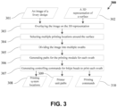
- FIG. 3 An embodiment of the operational, off-line programming step is shown in Figure 3 , where the off-line programming step generates paths to guide a motion platform to move a printing module relative to the surface of an object.
- the more specific workflow steps of the off-line programming step 300 include several sub-steps that facilitate overlaying the image of a livery design onto a 3D representation of the surface and dividing the image to be printed into multiple swaths. For printing a livery image on a large surface, it is advantageous to divide the livery design into multiple swaths and print the image in a swath-by-swath process.
- the motion platform may move its base after printing each or a few swaths, depending on the size of each swath, the surface geometry, and the printing scheme.
- sub-step 303 involves the overlaying of an image 301 of a livery design on the 3D representation 302 of the target surface.
- the 3D representation of the surface can be imported from a computer file. It can also be generated by sensor data of the surface acquired by the local sensing suite and the global motion tracking devices of the robotic printing system.
- sub-step 304 includes the process of determining if it is beneficial or necessary for the printing system to reach the entire surface from multiple locations rather than one single location and, if it is deemed to be beneficial or necessary, selecting a plurality of locations around the surface for the printing system to reach the entire surface.
- the livery image 301 is divided into multiple swaths.
- sub-step 306 After the image to be printed is divided into multiple swaths, multiple paths corresponding to the multiple swaths are produced in sub-step 306, wherein each path will guide the motion platform to move the printing module to print a corresponding swath of the image.
- controlling commands are generated in sub-step 307 for the printing module 200 to start or stop applying the printing material on the surface of the object.
- the next sub-step outputs the results of the off-line programming step, including a plurality of printing locations 308 for the printing system 100, pre-planned paths 309 that the printing module 200 will follow to print a plurality of swaths of the image, and printing commands 310 which starts or stops the ejection of the print material from the printing module 200.
- the workflow of the pre-printing and printing execution steps 400 comprises several sub-steps which include the uploading of a pre-planned path 401 to the motion controller 106 of the motion platform 101 and the uploading of a specific swath 421 of the livery image 301 to the printing module 200.
- the operational steps of the pre-printing and printing execution include two separate, parallel control threads. The first thread commands the motion platform 101 to move a printing module 200 to follow the pre-defined path 401 in sub-step 402.
- the first thread estimates the position, orientation, and velocity of the printing module 200 relative to the surface 109 based on measurements acquired by the local sensing suite and the global tracking device and uses the estimated position, orientation, and velocity as feedback to control the motion platform to maintain a desired position, orientation, and velocity of the printing module 200 relative to a surface 109.
- Sub-step 403 first fuses measurements obtained by various sensors in the local sensing suite and further fuses these measurements with measurements obtained by the global motion tracking devices into a first measurement product, which includes the position, orientation, and velocity of the print module with respect to the surface.
- this first measurement product is compared to the desired value of the position, orientation, and velocity of the printing module relative to the surface, and the error is used as motion feedback to generate correcting commands for the motion platform to maintain a desired position, orientation, and velocity of the printing module relative to the surface.
- Sub-step 404 checks the position of the printing module along the path 401 that the module is commanded to follow. Once a full path of a printing operation is completed, the printing module is moved to a home position by the motion platform in sub-step 405.
- the second thread controls the printing execution step whereby the timing of applying printing materials by the printing heads 201 in the printing module is controlled to apply printing material according to the swath 421.
- the second thread includes multiple sub-steps in the execution of the printing of the printing material. Specifically, the first sub-step 422 involves the system determining if the printing module 200 has reached the position to start printing said swath 421. In the next sub-step 423, a triggering signal is generated for controlling the timing of applying printing material from the printing heads 201 in the printing module 200.
- the triggering signal is generated by fusing the measurements from the one or more relative motion sensors 252 in the local sensing suite 250 or by fusing the measurements from the one or more relative motion sensors 252 in the local sensing suite 250 and the measurements from the one or more global motion tracking devices 105 into a second measurement product, which includes the travelled distance by the printing module 200 relative to the surface since the previous instance of the triggering signal.
- a new triggering signal is generated and sent to the printing module 200 to prompt the applying of the printing material according to the swath being printed.
- sub-step 424 monitors the printing progress and determines if the printing module 200 has completed printing this swath 421.
- sub-step 425 will then be executed whereby the printing module 200 is commanded to suspend applying the printing material.
- a post-printing step is executed which involves the servicing of the printing module and the motion platform.
- the printing module carried by said motion platform must maintain desired position, orientation, and velocity with respect to a surface in order to ensure the quality of printing results. Therefore the motion of said motion platform in following a pre-defined path is augmented during the printing procedure using sensor inputs to compensate for:
- the real-time processor 900 acquires raw data from one or more range sensors 254 in the local sensing suite 250; at step 502, said real-time processor 900 constructs a 3D representation of the observed area of said surface by using said range data; at step 503, said real-time processor 900 computes the position, orientation, and velocity of said printing module 200 with respect to said 3D representation of said surface; at step 504, said real-time processor 900 fuses said position, orientation, and velocity with the pose measurement obtained by the global motion tracking device 105; at step 505, said real-time processor 900 computes the errors of said position, orientation, and velocity with respect to their desired values; at step 506, said real-time processor 900 generates control commands from said errors; and at step 507, said real-time processor 900 sends said control commands to said motion controller 106 that controls
- the six DOF motion of the motion platform is decoupled, and each degree of motion is controlled separately.
- this system makes use of one or more range sensors in the local sensing suite to measure the standoff distance and the pitch and yaw angle of the printing module relative to the surface.
- data is acquired from the one or more range sensors in the local sensing suite, which are configured to measure the distance to said surface.
- a three-dimensional representation of the surface is then constructed using information from the range sensor data. Using this three-dimensional representation, the position and orientation of said printing module relative to the three-dimensional representation of said surface can be computed. The velocity of the printing module relative to surface can then be calculated by determining the change of its position and orientation from the previous time instant.
- Other degrees of motion of the printing module can be similarly regulated by feedback provided by the global motion tracking devices and the local sensing suite.
- the roll angle of the printing module relative to the surface of an object can be controlled with feedback of the printing module's orientation relative to the surface measured by the local sensing suite and feedback of the object's pose measured by the global motion tracking device.
- the two other translational DOF of the printing module's movement relative to the surface can be regulated with feedback provided by the global motion tracking device and the local sensing suite.
- Livery printing requires highly accurate, high-frequency triggering signals to control the timing of the printing heads to apply the correct type and amount of printing material for a given image pattern at the correct time at the right spot on a surface.
- the triggering signal for the printing head is implemented to aid in synchronizing the timing of applying printing material from the printing module with the motion of the printing module.
- the triggering signals can be generated through dead reckoning.
- a time-paced pulse sequence can serve as the triggering signal.
- a distance-paced signal can be generated according to the motion of the motion platform, which can be estimated from the measurements of its built-in joint encoders and its forward kinematics.
- these two approaches do not provide sufficient motion accuracy to achieve high quality printing.
- Typical accuracy of industrial robots is in the range of millimetres, while high-quality printing requires sub-millimetre accuracies.
- one or more relative motion sensors in the local sensing suite are used to measure the travel distance of the printing heads relative to a surface.
- the relative motion sensors may include any of one or more wheel encoders travelling on the surface, one or more non-contact optical sensors estimating relative motion, one or more non-contact capacitive sensors estimating relative motion, or a combination of thereof. Any measuring error of the relative motion sensors which occurs or accumulates through this particular embodiment may be further corrected by pose measurements obtained by a global motion tracking device.
- the global motion tracking device can be mounted at a fixture for measuring the pose of the printing module carried by the motion platform in a global reference frame. In some implementations, the global motion tracking device can be mounted on the motion platform. In this scenario, the global motion tracking device calculates its pose with respect to a global reference frame associated with the environment by measuring the pose of one or more markers attached to fixtures in the environment.
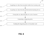
- the workflow 600 of generating highly accurate triggering signals by using one or more relative motion sensors and a global motion tracking device is shown.
- said real-time processor 900 acquires measurements from one or more relative motion sensors for measuring the travel distance of the printing module relative to a surface;
- said real-time processor 900 acquires pose measurements from said global motion tracking device 105 for tracking the pose of the printing module 200 in a global reference frame;
- said real-time processor 900 fuses said measurements from the two sets of sensors to estimate the travel distance of the printing module 200 relative to the surface, and at step 604, said real-time processor 900 generates a triggering pulse when the travelled distance of the printing module 200 is equal to or greater than a prescribed distance since the previous instance of the triggering signal; and step 605, said real-time processor 900 sends the triggering pulse to the printing module 200.
- the livery image may be applied using a method of dividing the image into multiple swaths, where each individual swath is printed on an incremental, "swath-by-swath" basis.
- adjacent swaths must be properly aligned.
- the correct alignment of the swaths is dependent on several conditions.
- the location of the livery design on the surface must be accurately registered to the motion platform.
- the pose of the livery design is preferably, accurately defined in the motion platform's base coordinate frame, in which the motion platform's motion is controlled.
- the first swath must be accurately printed at the correct location of the surface as it may be used as a reference for printing following swaths.
- the motion of the printing module must be accurately controlled to start printing each swath at the correct location and to maintain a desired shift relative to the previous swath for printing the current swath.
- the registration between the motion platform and the desired location of a livery image on a target surface is achieved by the following steps:
- the trajectory of the motion platform can be controlled to accurately print the first swath.
- the motion of the motion platform is controlled by sequential feedback from joint encoders build into the motion platform and a kinematic model of the motion platform.
- artificial features such as laser lines and semivisible pigmented inks are placed on the surface.
- Optical sensors in the local sensing suite are then employed to provide feedback for the motion platform through tracking these artificial features.
- a global motion tracking device is used to measure the pose of the printing module in a global reference frame, and such pose measurements are fed to the motion platform as control feedback to control its motion to accurately print the first swath.
- motion control of the motion platform may also be implemented to accurately align a swath relative to previously printed swaths.
- the motion control incorporates the aforementioned feedback from the built-in joint encoders and a kinematic model of the motion platform.
- a global motion tracking device is used to measure the pose of the printing module in a global reference frame, and these pose measurements are provided to the motion platform as control feedback to control its motion to accurately align a second swath to previously printed swaths.
- a coded pattern is simultaneously printed beside a swath and serves as a guiding cue for the motion platform to print the next swath.
- the motion platform may use one or more optical sensors in the local sensing suite to observe the previously printed swaths.
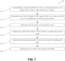
- the method for controlling the motion platform to align a swath to a previously printed swath includes the step of 701 commanding said motion platform 101 to move said printing module 200 to a location above one region of said printed swath; step 702 acquiring one or more images of said printed swath by using the optical sensors 253; step 703 detecting the boundary of said printed swath in said images; step 704 computing a shift for placing said new swath; step 705 calculating a path for the printing module 200 to print said new swath by adding the shift to the path of said printed swath; and step 706 sending said path to said motion controller 106 for controlling the motion platform 101 to move the printing module 200 to follow said path during printing said new swath.
- fusing the measurements from the global motion tracking devices and the local sensing suite is required to provide accurate motion feedback for improving the motion accuracy of the motion platform, generating highly accurate triggering signals, and ensuring proper swath alignment.
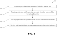
- FIG 8 a non-limiting example of a series of workflow steps 800 for achieving multi-sensor fusing of a variety of sensor measurements is shown.
- the real-time processor 900 acquires measurements from sensors of high update rate.
- the real-time processor 900 stacks said sensor measurements until it receives a measurement from a sensor of the lowest update rate.
- the real-time processor 900 derives a probabilistic quantification for the measurements from each sensor.
- the real-time processor 900 feeds all probabilistic measurements to a Bayes filter to reduce the uncertainties in the measurements.
- the Bayes filter models the uncertainties in the probabilistic measurements by a probability density function and recursively updates the probabilities of a plurality of beliefs of the measurements.
- the Bayes filter models the uncertainties in the probabilistic measurements by a set of discrete samples of measurements and recursively updates the probabilities of a plurality of beliefs of the measurements.
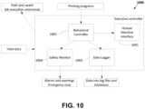
- Figure 9 provides a non-limiting example of an embodiment of a software implementation of the real-time processor 900.
- the processor 900 is programmed for aligning a second swath to a first swath which is already printed on the surface of the object.
- the swath detector 902 is capable of locating a first, already printed swath from images of the surface acquired by the optical sensors 253 in the local sensing suite 250 and using a variety of image processing techniques (e.g., edge detection, pattern matching, object recognition) to determine the boundaries of the first printed swath.
- the shift generator 903 is configured to then compute a shift that should be applied to the desired path for aligning the second swath with respect to said first swath.
- the robotic printing system may then follow the operation steps according to Figure 4 to print a next swath to be printed.
- the measurement fuser 904 filters and fuses measurements from the global motion tracking device 105 and the local sensing suite 250 to estimate and track the motion (i.e., position, orientation, speed, and/or direction) of the printing module 200 with respect to the surface.
- the path follower 905 compares the measured motion of the printing module 200 with the desired motion and generates correcting commands that should be applied to the motion of the motion platform to correct the difference between the measured and desired motion of the printing module 200 relative to the surface.
- Range data is acquired from range sensors in the local sensing suite, and pose measurements are acquired from the one or more global motion tracking devices.
- the range and pose measurements are then used to register a relative pose of the surface of the object, the mobile platform, and the printing module to a global reference frame.
- a 3D representation of the surface is then constructed from the range data of the surface, and a location and orientation of the range sensors in said 3D representation of said surface is computed.
- This representation enables the computation of a probabilistic quantification of the pose measurements from one or more measurement characteristics of the one or more range sensors and the global motion tracking devices to transform said probabilistic pose measurements of said mobile platform carrying the printing module relative to said surface into the global reference frame.
- the path correcting commands for the motion platform 101 are sent to the motion controller 106 to guide the motion platform 101 to move the printing module 200 along said path.
- the actuating device 101C in the motion platform 101 is controlled separately at a different rate for path correction.
- the actuating device commands are generated by the actuator positioner 907 and sent to the actuating device 101C directly.
- the swath corrector 908 also uses the fused information to compare said measured motion of the printing module 200 to the desired motion for the current swath of a livery image and adjusts the frequency of the triggering signals to be sent to the printing heads 201 by the triggering signal generator 909.
- the swath corrector 908 may receive the local sensor data directly, at the highest frequency available, and fuses it with the output of the measurement fuser 904 to generate triggering pulses for the printing heads 201. Telemetry data and sensor measurements from the printing module 200, the local sensing suite 250, the motion platform 101, and the global motion tracking device 105 are collected and sent to the executive controller 1000 for visualization and logging.
- the executive controller 1000 receives operational commands from an operator and monitors the status of other modules of the robotic printing system 100.
- the human machine interface 1001 provides various graphical views of live and historical data reported by the robotic printing system 100 to the operator.
- the operator can select a printing program to be executed by the system and can control the program's execution (e.g., start, stop, pause, and resume) through the tools provided by the human machine interface 1001.
- the behaviour controller 1002 loads the selected printing programs into the real-time processor 900 for printing the swaths specified in said printing programs.
- the data logger 1003 can log one or more types of the input and output data from the printing module 200, the local sensing suite 250, the motion platform 101, the global motion tracking device 105, the real-time processor 900, the executive controller 1000, and the associated computer systems. Logged data may be written into and stored in various storage mediums, such as computer memory, local hard drives, and external databases for both runtime access and post-operation analysis.
- the safety monitor 1004 can monitor one or more types of said input and output data, check system errors and violation of safety conditions (e.g., collision, low on printing material supply, loss of power, device failure, out of calibration), provide notifications (e.g., audible and/or visible alarm, warning message) to the operator, and slow down or stop the system's motion in the occurrence of an emergency.
- safety conditions e.g., collision, low on printing material supply, loss of power, device failure, out of calibration
- notifications e.g., audible and/or visible alarm, warning message
- the various instructions for completing the methods of printing a livery design may be stored in a computer readable storage medium by itself.
- the methods for printing the swaths, aligning swaths, maintaining the position and orientation of the print module, and incorporating and fusing global and local measurements may be combined into a single package and may be stored in combination on a computer readable storage medium.
- At least some of the elements of the systems described herein may be implemented by software, or a combination of software and hardware.
- Elements of the system that are implemented via software may be written in a high-level procedural language such as object oriented programming or a scripting language. Accordingly, the program code may be written in C, C++, C#, JavaScript, SQL, or any other suitable programming language and may comprise modules, classes, or other functional units of code as will be appreciated by those skilled in the art.
- At least some of the elements of the system that are implemented via software may be written in assembly language, machine language, or firmware as needed.
- the program code can be stored on a storage media or on a computer readable medium that is readable by a general or special purpose programmable computing device having a processor, an operating system, and the associated hardware and software that is necessary to implement the functionality of at least one of the embodiments described herein.
- the program code when read by the computing device, configures the computing device to operate in a new, specific and predefined manner in order to perform at least one of the methods described herein.
- the methods described herein are capable of being distributed in a computer program product comprising a computer readable medium that bears computer usable instructions for execution by one or more processors, to perform aspects of the methods described.
- the medium may be provided in various forms such as, but not limited to, one or more diskettes, compact disks, tapes, chips, USB keys, external hard drives, wire-line transmissions, satellite transmissions, internet transmissions or downloads, magnetic and electronic storage media, digital and analog signals, and the like.
- the computer useable instructions may also be in various forms, including compiled and non-compiled code.
Landscapes
- Engineering & Computer Science (AREA)
- Robotics (AREA)
- Mechanical Engineering (AREA)
- Human Computer Interaction (AREA)
- Manufacturing & Machinery (AREA)
- Ink Jet (AREA)
Claims (18)
- Verfahren zum Drucken eines Anstrichbildes unter Verwendung eines Systems (100), das ein Tintenstrahldruckmodul (200) auf einer Oberfläche (109) eines Objekts und zur Verwendung in Verbindung mit einer Bewegungsplattform (101A) beinhaltet, wobei das Verfahren die folgenden Schritte umfasst:Beschaffen von Daten von einer lokalen Erfassungseinheit (250), wobei die lokale Erfassungseinheit (250) einen beliebigen oder eine Kombination von einem oder mehreren Entfernungssensoren zum Beschaffen von Entfernungsdaten der Oberfläche (109) und einem oder mehreren Relativbewegungssensoren zum Messen einer Relativbewegung des Tintenstrahldruckmoduls (200) in Bezug auf die Oberfläche (109) umfasst;Beschaffen von Daten von einer oder mehreren globalen Bewegungsverfolgungsvorrichtungen (105);Erstellen eines ersten Messprodukts durch Zusammenführen der beschafften Daten von der lokalen Erfassungseinheit (250) und der einen oder den mehreren globalen Bewegungsverfolgungsvorrichtungen (105), um die Bewegungsplattform zu steuern, das Tintenstrahldruckmodul (200) über die Oberfläche (109) zu bewegen; undErstellen eines zweiten Messprodukts durch Zusammenführen der beschafften Daten von der lokalen Erfassungseinheit (250) und der einen oder den mehreren globalen Bewegungsverfolgungsvorrichtungen (105), um den Auswurfzeitpunkt des Druckmaterials aus dem Tintenstrahldruckmodul (200) zu steuern, wobei das zweite Messprodukt durch Zusammenführen von Daten von der lokalen Erfassungseinheit (250) und dem einen oder den mehreren globalen Bewegungsverfolgungsvorrichtungen (105) erstellt wird, um den Zeitablauf des Auftragens von Druckmaterial aus dem Tintenstrahldruckmodul (200) zu steuern durchEmpfangen einer oder mehrerer Wegstreckenmessungen von dem einen oder den mehreren Relativbewegungssensoren in der lokalen Erfassungseinheit (250);Zusammenführen der Wegstreckenmessungen mit Stellungsmessungen des Tintenstrahldruckmoduls (200), die von der einen oder den mehreren globalen Bewegungsverfolgungsvorrichtungen (105) erhalten werden;Erzeugen eines Auslöseimpulses, wenn die zusammengeführte Wegstreckenmessung gleich oder größer als eine vorbestimmte Wegstrecke ist; undSenden des Auslöseimpulses an das Tintenstrahldruckmodul (200), wobei der Auslöseimpuls einen Druckkopf des Tintenstrahldruckmoduls (200) steuert, das Druckmaterial aufzutragen.
- Verfahren nach Anspruch 1, wobei die lokale Erfassungseinheit (250) Folgendes umfasst:i) einen oder mehrere optische Sensoren zum Beschaffen eines oder mehrerer Bilder der Oberfläche (109).
- Verfahren nach Anspruch 1, wobei der eine oder die mehreren Relativbewegungssensoren zum Messen einer Relativbewegung des Tintenstrahldruckmoduls (200) in Bezug auf die Oberfläche (109) einen beliebigen von einem oder mehreren Radcodierern, die sich auf der Oberfläche (109) fortbewegen, einem oder mehreren berührungslosen optischen Sensoren, die eine relative Position oder Geschwindigkeit schätzen, einem oder mehreren berührungslosen kapazitiven Sensoren, die eine Relativbewegung schätzen, oder eine Kombination davon umfassen.
- Verfahren nach einem der Ansprüche 1 bis 3, wobei Erstellen eines ersten Messprodukts durch Zusammenführen der beschafften Daten von der lokalen Erfassungseinheit (250) und der einen oder den mehreren globalen Bewegungsverfolgungsvorrichtungen (105) die folgenden Schritte umfasst:i) Beschaffen von Entfernungsdaten von einem oder mehreren Entfernungssensoren in der lokalen Sensoreinheit (250), um die Distanz des Tintenstrahldruckmoduls (200) relativ zu der Oberfläche (109) zu messen;ii) Beschaffen von Positions- und Orientierungsmessungen des Tintenstrahldruckmoduls (200) und der Oberfläche (109) von der einen oder den mehreren globalen Bewegungsverfolgungsvorrichtungen (105);iii) Gestalten einer 3D-Darstellung der Oberfläche (109) anhand der Daten von den Entfernungssensoren;iv) Berechnen einer Position und Orientierung des Tintenstrahldruckmoduls in der 3D-Darstellung der Oberfläche (109);v) Ableiten einer probabilistischen Quantifizierung der berechneten Position und Orientierung des Tintenstrahldruckmoduls (200) aus einer oder mehreren Messeigenschaften des einen oder der mehreren Entfernungssensoren;vi) Ableiten einer probabilistischen Quantifizierung der gemessenen Positions- und Orientierungsmessungen des Druckmoduls und der Oberfläche (109) aus einer oder mehreren Messeigenschaften der globalen Bewegungsverfolgungsvorrichtungen (105) und Berechnen der Position und Orientierung des Tintenstrahldruckmoduls (200) relativ zu der Oberfläche (109) aus den Positions- und Orientierungsmessungen des Tintenstrahldruckmoduls (200) und der Oberfläche (109) aus den globalen Bewegungsverfolgungsvorrichtungen (105); undvii) Zusammenfügen der probabilistischen Quantifizierung der Position und Orientierung des Tintenstrahldruckmoduls (200) relativ zu der Oberfläche (109) von dem einen oder den mehreren Entfernungssensoren und der probabilistischen Quantifizierung der Position des Tintenstrahldruckmoduls (200) relativ zu der Oberfläche (109) von den globalen Bewegungsverfolgungsvorrichtungen (105).
- Verfahren nach einem der Ansprüche 1 bis 4, wobei Steuern einer Bewegungsplattform, das Tintenstrahldruckmodul (200) über die Oberfläche (109) zu bewegen, die folgenden Schritte umfasst:i) Befehligen der Bewegungsplattform, das Druckmodul entlang eines vorgeplanten Pfades relativ zu der Oberfläche (109) zu bewegen;ii) Berechnen eines Fehlers zwischen dem ersten Messprodukt und einer gewünschten Position, Orientierung und Geschwindigkeit des Tintenstrahldruckmoduls (200) relativ zu der Oberfläche (109); undiii) Anwenden einer Vielzahl von Bewegungskorrekturbefehlen auf die Bewegungsplattform, um die Fehler in der Position, Orientierung und Geschwindigkeit des Tintenstrahldruckmoduls (200) relativ zu der Oberfläche (109) zu korrigieren.
- Verfahren nach einem der Ansprüche 1 bis 5, wobei Drucken eines Anstrichbildes weiter Folgendes umfasst:i) Steuern der mobilen Plattform, das Tintenstrahldruckmodul (200) so zu bewegen, dass es einem ersten Pfad folgt, der einem ersten Streifen der Vielzahl von Streifen entspricht, wobei ein Druckmaterial vom Tintenstrahldruckmodul (200) aufgetragen wird, um einen ersten gedruckten Streifen zu bilden, der der Vielzahl von Streifen entspricht;ii) Bestimmen einer Stelle für einen nächsten zu druckenden Streifen und Ausrichten des nächsten zu druckenden Streifens mit dem ersten gedruckten Streifen;iii) Steuern des Tintenstrahldruckmoduls (200), einem Pfad zu folgen, der dem nächsten zu druckenden Streifen entspricht, wobei das Druckmaterial von dem Tintenstrahldruckmodul (200) aufgetragen wird, um einen nächsten gedruckten Streifen zu bilden; undiv) Wiederholen der Schritte ii) bis iii), bis die Vielzahl von Streifen gedruckt worden ist, um eine Vielzahl gedruckter Streifen zu bilden.
- Verfahren nach Anspruch 6, wobei Auftragen des Druckmaterials von dem Tintenstrahldruckmodul (200) zum Bilden des nächsten gedruckten Streifens Auftragen des Druckmaterials auf eine Vielzahl von Bereichen in unmittelbarer Nähe der einen oder mehreren Grenzen des ersten Streifens mit einer verringerten Intensität umfasst, wodurch der Pfad des nächsten zu druckenden Streifens verschoben wird, um eine Überlappung zwischen dem ersten gedruckten Streifen und dem nächsten gedruckten Streifen zu ermöglichen.
- System zum Auftragen eines Anstrichbildes auf die Oberfläche eines Objekts, umfassend:i) ein Tintenstrahldruckmodul (200), das auf einer Bewegungsplattform montiert und dazu konfiguriert ist, eine Vielzahl benachbarter Streifen eines Druckmaterials aufzutragen, um ein Bild auf einer Oberfläche zu erzeugen, umfassend:a) einen oder mehrere Tanks zum Lagern des Druckmaterials,b) eine Vielzahl von Druckköpfen zum Auftragen des Druckmaterials,ii) eine lokale Erfassungseinheit (250), die dazu konfiguriert ist, ein oder mehrere Bilder der Oberfläche (109) zu beschaffen und die Bewegung des Tintenstrahldruckmoduls (200) relativ zu der Oberfläche (109) zu messen, wobei die lokale Erfassungseinheit (250) einen beliebigen oder eine Kombination umfasst von: einem oder mehreren Entfernungssensoren zum Messen einer Distanz zu der Oberfläche (109); und einem oder mehreren Relativbewegungssensoren zum Messen einer Relativbewegung des Tintenstrahldruckmoduls (200) in Bezug auf die Oberfläche (109).iii) eine oder mehrere globale Bewegungsverfolgungsvorrichtungen (105), die zum Messen der Stellung des Tintenstrahldruckmoduls (200), der Bewegungsplattform und der Oberfläche (109) des Objekts konfiguriert sind;iv) einen Echtzeitprozessor, der mit dem Druckmodul, der Bewegungsplattform, der lokalen Erfassungseinheit (250) und den globalen Bewegungsverfolgungsvorrichtungen (105) verbunden ist, wobei der Echtzeitprozessor dazu programmiert ist, ein erstes Messprodukt durch Zusammenführen der beschafften Daten von der lokalen Erfassungseinheit (250) und der einen oder den mehreren globalen Bewegungsverfolgungsvorrichtungen (105) zu erstellen, um die Bewegungsplattform zu steuern, das Tintenstrahldruckmodul (200) über die Oberfläche (109) zu bewegen, und ein zweites Messprodukt durch Zusammenführen der beschafften Daten von der lokalen Erfassungseinheit (250) und der einen oder den mehreren globalen Bewegungsverfolgungsvorrichtungen (105) zu erstellen, um den Auswurfzeitpunkt des Druckmaterials aus dem Tintenstrahldruckmodul (200) zu steuern durchEmpfangen einer oder mehrerer Wegstreckenmessungen von dem einen oder den mehreren Relativbewegungssensoren in der lokalen Erfassungseinheit (250);Zusammenführen der Wegstreckenmessungen mit Stellungsmessungen des Tintenstrahldruckmoduls (200), die von der einen oder den mehreren globalen Bewegungsverfolgungsvorrichtungen (105) erhalten werden;Erzeugen eines Auslöseimpulses, wenn die zusammengeführte Wegstreckenmessung gleich oder größer als eine vorbestimmte Wegstrecke ist; undSenden des Auslöseimpulses an das Tintenstrahldruckmodul (200), wobei der Auslöseimpuls einen Druckkopf des Tintenstrahldruckmoduls (200) steuert, das Druckmaterial aufzutragen; undv) einen ausführenden Computer, der mit dem Echtzeitprozessor verbunden ist.
- System nach Anspruch 8, wobei die lokale Erfassungseinheit (250) Folgendes umfasst:i) einen oder mehrere optische Sensoren zum Beschaffen eines oder mehrerer Bilder der Oberfläche (109).
- System nach Anspruch 8 oder 9, wobei das Tintenstrahldruckmodul (200) weiter eine oder mehrere Materialaushärtungsvorrichtungen, einschließlich UV-Lampen zum Aushärten der Vielzahl benachbarter Streifen des Druckmaterials, umfasst.
- System nach einem der Ansprüche 8 bis 10, wobei die Bewegungsplattform ein beliebiges von einem Führungsrahmen, einem mehrachsigen Translationstisch, einem mobilen Fahrzeug, einem mehrachsigen Robotermanipulator, einer Betätigungsvorrichtung, oder eine Kombination davon umfasst.
- System nach Anspruch 11, wobei die Bewegungsplattform den Translationstisch, den von dem Translationstisch getragenen mehrachsigen Robotermanipulator und die an einem Endeffektor des mehrachsigen Robotermanipulators montierte Betätigungsvorrichtung umfasst.
- System nach einem der Ansprüche 8 bis 12, wobei der Echtzeitprozessor ein Computer ist, der mit Anweisungen programmiert ist, eine Vielzahl von Messungen von der lokalen Erfassungseinheit (250) und den globalen Bewegungsverfolgungsvorrichtungen (105) zusammenzuführen, um die Bewegung des Tintenstrahldruckmoduls (200) relativ zu der Oberfläche (109) zu schätzen.
- System nach einem der Ansprüche 8 bis 13, wobei der Echtzeitprozessor mit Anweisungen programmiert ist, die Bewegung der Bewegungsplattform zu steuern, indem er einen vordefinierten Pfad empfängt und der Bewegungsplattform den Befehl gibt, dem vordefinierten Pfad zu folgen.
- System nach einem der Ansprüche 8 bis 14, wobei der Echtzeitprozessor mit Anweisungen zum Berechnen einer Vielzahl von Bewegungskorrekturbefehlen für die Bewegungsplattform programmiert ist, um eine gewünschte Position, Orientierung und Geschwindigkeit des Tintenstrahldruckmoduls (200) relativ zu der Oberfläche (109) beizubehalten.
- System nach Anspruch 15, wobei Berechnen einer Vielzahl von Bewegungskorrekturbefehlen für die Bewegungsplattform, um eine gewünschte Position, Orientierung und Geschwindigkeit des Tintenstrahldruckmoduls (200) relativ zu der Oberfläche (109) beizubehalten, die folgenden Schritte umfasst:i) Beschaffen von Daten von einem oder mehreren Entfernungssensoren, die eine Distanz zu der Oberfläche (109) messen;ii) Erzeugen einer 3D-Darstellung der Oberfläche (109) aus den beschafften Daten;iii) Berechnen einer Position, Orientierung und Geschwindigkeit des Tintenstrahldruckmoduls (200) relativ zu der 3D-Darstellung der Oberfläche (109);iv) Zusammenführen der Stellungsmessungen des Tintenstrahldruckmoduls (200) von einer oder mehreren globalen Bewegungsverfolgungsvorrichtungen (105) und der Positions-, Orientierungs- und Geschwindigkeitsschätzung aus den Entfernungsdaten und Berechnen einer gefilterten Position, Orientierung und Geschwindigkeit des Tintenstrahldruckmoduls (200) relativ zu der Oberfläche (109);v) Berechnen eines Fehlers zwischen den gefilterten Werten und den gewünschten Werten der Position, Orientierung und Geschwindigkeit des Tintenstrahldruckmoduls (200) relativ zu der Oberfläche (109); undvi) Anwenden einer Vielzahl von Bewegungskorrekturbefehlen auf die Bewegungsplattform, um den Fehler in der Position, Orientierung und Geschwindigkeit des Tintenstrahldruckmoduls (200) relativ zu der Oberfläche (109) zu korrigieren.
- System nach einem der Ansprüche 8 bis 16, wobei der Echtzeitprozessor mit Anweisungen zum Steuern der Bewegung der Bewegungsplattform programmiert ist, um eine Vielzahl benachbarter Streifen eines Anstrichbildes auszurichten.
- System nach Anspruch 17, wobei Steuern der Bewegung der Bewegungsplattform zum Ausrichten einer Vielzahl benachbarter Streifen eines Anstrichbildes die folgenden Schritte umfasst:i) Befehligen der Bewegungsplattform, das Tintenstrahldruckmodul (200) zu einem Bereich in der Nähe eines ersten gedruckten Streifens zu bewegen;ii) Beschaffen eines oder mehrerer Bilder des ersten gedruckten Streifens von einem oder mehreren optischen Sensoren in der lokalen Erfassungseinheit (250);i) Detektieren einer Vielzahl von Grenzen des ersten gedruckten Streifens anhand des einen oder der mehreren Bilder des ersten gedruckten Streifens;ii) Berechnen eines verschobenen Pfads, der einem nächsten zu druckenden Streifen entspricht, aus den detektierten Grenzen; undiii) Steuern der Bewegungsplattform, das Tintenstrahldruckmodul (200) so zu bewegen, dass es dem verschobenen Pfad folgt, um den nächsten Streifen zu drucken.
Applications Claiming Priority (2)
| Application Number | Priority Date | Filing Date | Title |
|---|---|---|---|
| US201762552980P | 2017-08-31 | 2017-08-31 | |
| PCT/CA2018/051024 WO2019041027A1 (en) | 2017-08-31 | 2018-08-24 | ROBOTIC PRINTING SYSTEM OF ADVERTISING LOGO |
Publications (4)
| Publication Number | Publication Date |
|---|---|
| EP3676102A1 EP3676102A1 (de) | 2020-07-08 |
| EP3676102A4 EP3676102A4 (de) | 2021-05-05 |
| EP3676102C0 EP3676102C0 (de) | 2024-05-22 |
| EP3676102B1 true EP3676102B1 (de) | 2024-05-22 |
Family
ID=65524827
Family Applications (1)
| Application Number | Title | Priority Date | Filing Date |
|---|---|---|---|
| EP18852216.3A Active EP3676102B1 (de) | 2017-08-31 | 2018-08-24 | Robotisches beschriftungsdrucksystem |
Country Status (4)
| Country | Link |
|---|---|
| US (2) | US11571911B2 (de) |
| EP (1) | EP3676102B1 (de) |
| CA (1) | CA3062036C (de) |
| WO (1) | WO2019041027A1 (de) |
Families Citing this family (13)
| Publication number | Priority date | Publication date | Assignee | Title |
|---|---|---|---|---|
| CN112041635B (zh) * | 2018-04-03 | 2024-04-09 | 三菱电机株式会社 | 移动机、地图管理装置、定位系统、控制电路及存储介质 |
| US11052687B2 (en) * | 2019-06-26 | 2021-07-06 | Xerox Corporation | System and method for analyzing the surface of a three-dimensional object to be printed by a printhead mounted to an articulating arm |
| US20210237116A1 (en) * | 2020-02-03 | 2021-08-05 | Ross-Hime Designs, Inc. | Robotic marking system |
| US12434383B2 (en) * | 2020-12-02 | 2025-10-07 | Fanuc Corporation | 3D printer using robot and control apparatus for robot |
| JP7600672B2 (ja) * | 2020-12-23 | 2024-12-17 | セイコーエプソン株式会社 | 立体物印刷装置および立体物印刷方法 |
| DE102021108563A1 (de) * | 2021-04-07 | 2022-10-13 | Dürr Systems Ag | Bahnkorrekturverfahren für eine Beschichtungsanlage |
| EP4393718A1 (de) | 2022-12-26 | 2024-07-03 | Airbus Operations (S.A.S.) | Tintenstrahldruckvorrichtung mit mindestens zwei servoschleifen, die für grosse komplexe oberflächen geeignet sind |
| JP2025018520A (ja) * | 2023-07-27 | 2025-02-06 | セイコーエプソン株式会社 | 印刷方法およびロボットシステム |
| CN117565575B (zh) * | 2023-11-17 | 2024-08-13 | 广州市森扬电子科技有限公司 | 一种喷墨打印机喷头自动调节的方法、设备及存储介质 |
| CN117605283A (zh) * | 2023-11-23 | 2024-02-27 | 中交第一公路勘察设计研究院有限公司 | 面向混凝土3d打印条带路径实时测控系统及方法 |
| CN120716353A (zh) * | 2024-03-27 | 2025-09-30 | 精工爱普生株式会社 | 立体物印刷装置以及路径生成方法 |
| CN119037037B (zh) * | 2024-08-20 | 2025-03-25 | 广州市森扬电子科技有限公司 | 一种打印机动作监控方法、设备及其存储介质 |
| CN120422472B (zh) * | 2025-07-03 | 2025-09-02 | 深圳市智能派科技有限公司 | 基于出料头动态分析的3d打印平台调平方法及系统 |
Family Cites Families (13)
| Publication number | Priority date | Publication date | Assignee | Title |
|---|---|---|---|---|
| US7350890B2 (en) | 2004-08-26 | 2008-04-01 | The Boeing Company | Apparatus and methods for applying images to a surface |
| US20060068109A1 (en) | 2004-09-15 | 2006-03-30 | Airbus Deutschland Gmbh | Painting device, painting arrangement, method for painting a curved surface of an object, and use of an inkjet device for painting an aircraft |
| EP2229282A1 (de) | 2007-12-31 | 2010-09-22 | Exatec, LLC. | Vorrichtung und verfahren zum drucken dreidimensionaler artikel |
| EP2433716A1 (de) * | 2010-09-22 | 2012-03-28 | Hexagon Technology Center GmbH | Oberflächenspritzvorrichtung mit einem Kontrollmechanismus für die Düse und einer entsprechenden Methode |
| EP2799150B1 (de) * | 2013-05-02 | 2016-04-27 | Hexagon Technology Center GmbH | Graphisches Auftragssystem |
| DE102012006371A1 (de) | 2012-03-29 | 2012-07-05 | Heidelberger Druckmaschinen Aktiengesellschaft | Verfahren zum Bedrucken eines Objekts |
| DE102012006370A1 (de) * | 2012-03-29 | 2013-10-02 | Heidelberger Druckmaschinen Aktiengesellschaft | System zum Bedrucken eines Objekts |
| EP2872336B1 (de) * | 2012-07-10 | 2019-05-15 | Hewlett-Packard Development Company, L.P. | Verfahren zum kontrollieren eines druckers mit zumindest einem druckbalken |
| JP6410022B2 (ja) * | 2013-09-06 | 2018-10-24 | パナソニックIpマネジメント株式会社 | マスタスレーブロボットの制御装置及び制御方法、ロボット、マスタスレーブロボットの制御プログラム、並びに、マスタスレーブロボットの制御用集積電子回路 |
| US9446585B2 (en) | 2014-08-22 | 2016-09-20 | Massachusetts Institute Of Technology | Methods and apparatus for handheld inkjet printer |
| US9781350B2 (en) | 2015-09-28 | 2017-10-03 | Qualcomm Incorporated | Systems and methods for performing automatic zoom |
| US9527275B1 (en) | 2016-02-16 | 2016-12-27 | Southwest Research Institute | High accuracy inkjet printing |
| WO2018098394A1 (en) * | 2016-11-25 | 2018-05-31 | Glowforge Inc. | Fabrication with image tracing |
-
2018
- 2018-08-24 EP EP18852216.3A patent/EP3676102B1/de active Active
- 2018-08-24 US US16/643,289 patent/US11571911B2/en active Active
- 2018-08-24 CA CA3062036A patent/CA3062036C/en active Active
- 2018-08-24 WO PCT/CA2018/051024 patent/WO2019041027A1/en not_active Ceased
-
2021
- 2021-12-14 US US17/550,296 patent/US11865852B2/en active Active
Also Published As
| Publication number | Publication date |
|---|---|
| US11571911B2 (en) | 2023-02-07 |
| CA3062036A1 (en) | 2019-03-07 |
| US11865852B2 (en) | 2024-01-09 |
| WO2019041027A1 (en) | 2019-03-07 |
| CA3062036C (en) | 2021-05-11 |
| EP3676102A1 (de) | 2020-07-08 |
| US20220097411A1 (en) | 2022-03-31 |
| EP3676102C0 (de) | 2024-05-22 |
| EP3676102A4 (de) | 2021-05-05 |
| US20200198367A1 (en) | 2020-06-25 |
Similar Documents
| Publication | Publication Date | Title |
|---|---|---|
| US11865852B2 (en) | Robotic livery printing system | |
| JP6157174B2 (ja) | 対象物に印刷を行うシステム | |
| KR101572917B1 (ko) | 그래픽 적용 시스템 | |
| US9844792B2 (en) | Surface spattering device | |
| US20190030886A1 (en) | Metrology-Based Path Planning For Inkjet Printing Along A Contoured Surface | |
| US5380978A (en) | Method and apparatus for assembly of car bodies and other 3-dimensional objects | |
| EP2697604B1 (de) | Vermessungssystem zur bestimmung von 3d-koordinaten einer objektoberfläche | |
| KR20220005558A (ko) | 코팅 방법 및 대응하는 코팅 설비 | |
| US20240181484A1 (en) | Path correction method for a coating system | |
| US20240033847A1 (en) | Method and controller for controlling a laser processing process on a surface of a workpiece and processing system for processing a surface of a workpiece by means of a laser processing process | |
| US12491722B2 (en) | Inkjet printing device, comprising at least two servocontrol loops, suitable for large complex surfaces | |
| US20250347512A1 (en) | Surface height measurements using a scanning path following a toolpath and methods thereof | |
| JP2006320825A (ja) | 自動制御塗装車両 | |
| WO2018185892A1 (ja) | 位置検出装置、および塗装補助システム | |
| CN121661141A (zh) | 一种以板材本体为空间基准的复合agv再定位系统及方法 |
Legal Events
| Date | Code | Title | Description |
|---|---|---|---|
| STAA | Information on the status of an ep patent application or granted ep patent |
Free format text: STATUS: THE INTERNATIONAL PUBLICATION HAS BEEN MADE |
|
| PUAI | Public reference made under article 153(3) epc to a published international application that has entered the european phase |
Free format text: ORIGINAL CODE: 0009012 |
|
| STAA | Information on the status of an ep patent application or granted ep patent |
Free format text: STATUS: REQUEST FOR EXAMINATION WAS MADE |
|
| 17P | Request for examination filed |
Effective date: 20200309 |
|
| AK | Designated contracting states |
Kind code of ref document: A1 Designated state(s): AL AT BE BG CH CY CZ DE DK EE ES FI FR GB GR HR HU IE IS IT LI LT LU LV MC MK MT NL NO PL PT RO RS SE SI SK SM TR |
|
| AX | Request for extension of the european patent |
Extension state: BA ME |
|
| DAV | Request for validation of the european patent (deleted) | ||
| DAX | Request for extension of the european patent (deleted) | ||
| REG | Reference to a national code |
Ref legal event code: R079 Ipc: B41J0003407000 Ref country code: DE Ref legal event code: R079 Ref document number: 602018069878 Country of ref document: DE Free format text: PREVIOUS MAIN CLASS: B41J0029380000 Ipc: B41J0003407000 |
|
| A4 | Supplementary search report drawn up and despatched |
Effective date: 20210408 |
|
| RIC1 | Information provided on ipc code assigned before grant |
Ipc: B41J 3/407 20060101AFI20210331BHEP Ipc: B41J 29/38 20060101ALI20210331BHEP Ipc: B25J 11/00 20060101ALI20210331BHEP |
|
| STAA | Information on the status of an ep patent application or granted ep patent |
Free format text: STATUS: EXAMINATION IS IN PROGRESS |
|
| 17Q | First examination report despatched |
Effective date: 20230111 |
|
| GRAP | Despatch of communication of intention to grant a patent |
Free format text: ORIGINAL CODE: EPIDOSNIGR1 |
|
| STAA | Information on the status of an ep patent application or granted ep patent |
Free format text: STATUS: GRANT OF PATENT IS INTENDED |
|
| INTG | Intention to grant announced |
Effective date: 20231215 |
|
| GRAS | Grant fee paid |
Free format text: ORIGINAL CODE: EPIDOSNIGR3 |
|
| GRAA | (expected) grant |
Free format text: ORIGINAL CODE: 0009210 |
|
| STAA | Information on the status of an ep patent application or granted ep patent |
Free format text: STATUS: THE PATENT HAS BEEN GRANTED |
|
| AK | Designated contracting states |
Kind code of ref document: B1 Designated state(s): AL AT BE BG CH CY CZ DE DK EE ES FI FR GB GR HR HU IE IS IT LI LT LU LV MC MK MT NL NO PL PT RO RS SE SI SK SM TR |
|
| REG | Reference to a national code |
Ref country code: GB Ref legal event code: FG4D |
|
| REG | Reference to a national code |
Ref country code: CH Ref legal event code: EP |
|
| REG | Reference to a national code |
Ref country code: DE Ref legal event code: R096 Ref document number: 602018069878 Country of ref document: DE |
|
| REG | Reference to a national code |
Ref country code: IE Ref legal event code: FG4D |
|
| RAP4 | Party data changed (patent owner data changed or rights of a patent transferred) |
Owner name: MACDONALD, DETTWILER AND ASSOCIATES INC. |
|
| U01 | Request for unitary effect filed |
Effective date: 20240620 |
|
| U07 | Unitary effect registered |
Designated state(s): AT BE BG DE DK EE FI FR IT LT LU LV MT NL PT SE SI Effective date: 20240628 |
|
| PG25 | Lapsed in a contracting state [announced via postgrant information from national office to epo] |
Ref country code: IS Free format text: LAPSE BECAUSE OF FAILURE TO SUBMIT A TRANSLATION OF THE DESCRIPTION OR TO PAY THE FEE WITHIN THE PRESCRIBED TIME-LIMIT Effective date: 20240922 |
|
| PG25 | Lapsed in a contracting state [announced via postgrant information from national office to epo] |
Ref country code: HR Free format text: LAPSE BECAUSE OF FAILURE TO SUBMIT A TRANSLATION OF THE DESCRIPTION OR TO PAY THE FEE WITHIN THE PRESCRIBED TIME-LIMIT Effective date: 20240522 |
|
| PG25 | Lapsed in a contracting state [announced via postgrant information from national office to epo] |
Ref country code: GR Free format text: LAPSE BECAUSE OF FAILURE TO SUBMIT A TRANSLATION OF THE DESCRIPTION OR TO PAY THE FEE WITHIN THE PRESCRIBED TIME-LIMIT Effective date: 20240823 |
|
| PG25 | Lapsed in a contracting state [announced via postgrant information from national office to epo] |
Ref country code: ES Free format text: LAPSE BECAUSE OF FAILURE TO SUBMIT A TRANSLATION OF THE DESCRIPTION OR TO PAY THE FEE WITHIN THE PRESCRIBED TIME-LIMIT Effective date: 20240522 |
|
| PG25 | Lapsed in a contracting state [announced via postgrant information from national office to epo] |
Ref country code: PL Free format text: LAPSE BECAUSE OF FAILURE TO SUBMIT A TRANSLATION OF THE DESCRIPTION OR TO PAY THE FEE WITHIN THE PRESCRIBED TIME-LIMIT Effective date: 20240522 |
|
| U20 | Renewal fee for the european patent with unitary effect paid |
Year of fee payment: 7 Effective date: 20240925 |
|
| PG25 | Lapsed in a contracting state [announced via postgrant information from national office to epo] |
Ref country code: PL Free format text: LAPSE BECAUSE OF FAILURE TO SUBMIT A TRANSLATION OF THE DESCRIPTION OR TO PAY THE FEE WITHIN THE PRESCRIBED TIME-LIMIT Effective date: 20240522 Ref country code: NO Free format text: LAPSE BECAUSE OF FAILURE TO SUBMIT A TRANSLATION OF THE DESCRIPTION OR TO PAY THE FEE WITHIN THE PRESCRIBED TIME-LIMIT Effective date: 20240822 Ref country code: IS Free format text: LAPSE BECAUSE OF FAILURE TO SUBMIT A TRANSLATION OF THE DESCRIPTION OR TO PAY THE FEE WITHIN THE PRESCRIBED TIME-LIMIT Effective date: 20240922 Ref country code: HR Free format text: LAPSE BECAUSE OF FAILURE TO SUBMIT A TRANSLATION OF THE DESCRIPTION OR TO PAY THE FEE WITHIN THE PRESCRIBED TIME-LIMIT Effective date: 20240522 Ref country code: GR Free format text: LAPSE BECAUSE OF FAILURE TO SUBMIT A TRANSLATION OF THE DESCRIPTION OR TO PAY THE FEE WITHIN THE PRESCRIBED TIME-LIMIT Effective date: 20240823 Ref country code: ES Free format text: LAPSE BECAUSE OF FAILURE TO SUBMIT A TRANSLATION OF THE DESCRIPTION OR TO PAY THE FEE WITHIN THE PRESCRIBED TIME-LIMIT Effective date: 20240522 Ref country code: RS Free format text: LAPSE BECAUSE OF FAILURE TO SUBMIT A TRANSLATION OF THE DESCRIPTION OR TO PAY THE FEE WITHIN THE PRESCRIBED TIME-LIMIT Effective date: 20240822 |
|
| PG25 | Lapsed in a contracting state [announced via postgrant information from national office to epo] |
Ref country code: CZ Free format text: LAPSE BECAUSE OF FAILURE TO SUBMIT A TRANSLATION OF THE DESCRIPTION OR TO PAY THE FEE WITHIN THE PRESCRIBED TIME-LIMIT Effective date: 20240522 |
|
| PG25 | Lapsed in a contracting state [announced via postgrant information from national office to epo] |
Ref country code: SK Free format text: LAPSE BECAUSE OF FAILURE TO SUBMIT A TRANSLATION OF THE DESCRIPTION OR TO PAY THE FEE WITHIN THE PRESCRIBED TIME-LIMIT Effective date: 20240522 Ref country code: RO Free format text: LAPSE BECAUSE OF FAILURE TO SUBMIT A TRANSLATION OF THE DESCRIPTION OR TO PAY THE FEE WITHIN THE PRESCRIBED TIME-LIMIT Effective date: 20240522 |
|
| PG25 | Lapsed in a contracting state [announced via postgrant information from national office to epo] |
Ref country code: SM Free format text: LAPSE BECAUSE OF FAILURE TO SUBMIT A TRANSLATION OF THE DESCRIPTION OR TO PAY THE FEE WITHIN THE PRESCRIBED TIME-LIMIT Effective date: 20240522 |
|
| PG25 | Lapsed in a contracting state [announced via postgrant information from national office to epo] |
Ref country code: SM Free format text: LAPSE BECAUSE OF FAILURE TO SUBMIT A TRANSLATION OF THE DESCRIPTION OR TO PAY THE FEE WITHIN THE PRESCRIBED TIME-LIMIT Effective date: 20240522 Ref country code: SK Free format text: LAPSE BECAUSE OF FAILURE TO SUBMIT A TRANSLATION OF THE DESCRIPTION OR TO PAY THE FEE WITHIN THE PRESCRIBED TIME-LIMIT Effective date: 20240522 Ref country code: RO Free format text: LAPSE BECAUSE OF FAILURE TO SUBMIT A TRANSLATION OF THE DESCRIPTION OR TO PAY THE FEE WITHIN THE PRESCRIBED TIME-LIMIT Effective date: 20240522 Ref country code: CZ Free format text: LAPSE BECAUSE OF FAILURE TO SUBMIT A TRANSLATION OF THE DESCRIPTION OR TO PAY THE FEE WITHIN THE PRESCRIBED TIME-LIMIT Effective date: 20240522 |
|
| REG | Reference to a national code |
Ref country code: DE Ref legal event code: R097 Ref document number: 602018069878 Country of ref document: DE |
|
| PLBE | No opposition filed within time limit |
Free format text: ORIGINAL CODE: 0009261 |
|
| STAA | Information on the status of an ep patent application or granted ep patent |
Free format text: STATUS: NO OPPOSITION FILED WITHIN TIME LIMIT |
|
| REG | Reference to a national code |
Ref country code: CH Ref legal event code: PL |
|
| PG25 | Lapsed in a contracting state [announced via postgrant information from national office to epo] |
Ref country code: MC Free format text: LAPSE BECAUSE OF FAILURE TO SUBMIT A TRANSLATION OF THE DESCRIPTION OR TO PAY THE FEE WITHIN THE PRESCRIBED TIME-LIMIT Effective date: 20240522 Ref country code: CH Free format text: LAPSE BECAUSE OF NON-PAYMENT OF DUE FEES Effective date: 20240831 |
|
| 26N | No opposition filed |
Effective date: 20250225 |
|
| U1N | Appointed representative for the unitary patent procedure changed after the registration of the unitary effect |
Representative=s name: SANGER, PHILLIP SIMON; GB |
|
| U20 | Renewal fee for the european patent with unitary effect paid |
Year of fee payment: 8 Effective date: 20250827 |
|
| PGFP | Annual fee paid to national office [announced via postgrant information from national office to epo] |
Ref country code: GB Payment date: 20250820 Year of fee payment: 8 |
|
| PGFP | Annual fee paid to national office [announced via postgrant information from national office to epo] |
Ref country code: IE Payment date: 20250820 Year of fee payment: 8 |
|
| PG25 | Lapsed in a contracting state [announced via postgrant information from national office to epo] |
Ref country code: CY Free format text: LAPSE BECAUSE OF FAILURE TO SUBMIT A TRANSLATION OF THE DESCRIPTION OR TO PAY THE FEE WITHIN THE PRESCRIBED TIME-LIMIT; INVALID AB INITIO Effective date: 20180824 |
|
| PG25 | Lapsed in a contracting state [announced via postgrant information from national office to epo] |
Ref country code: HU Free format text: LAPSE BECAUSE OF FAILURE TO SUBMIT A TRANSLATION OF THE DESCRIPTION OR TO PAY THE FEE WITHIN THE PRESCRIBED TIME-LIMIT; INVALID AB INITIO Effective date: 20180824 |