EP3676129B1 - Véhicule automobile avec compartiment de rangement de sous-siège extensible - Google Patents
Véhicule automobile avec compartiment de rangement de sous-siège extensible Download PDFInfo
- Publication number
- EP3676129B1 EP3676129B1 EP18766471.9A EP18766471A EP3676129B1 EP 3676129 B1 EP3676129 B1 EP 3676129B1 EP 18766471 A EP18766471 A EP 18766471A EP 3676129 B1 EP3676129 B1 EP 3676129B1
- Authority
- EP
- European Patent Office
- Prior art keywords
- front panel
- panel assembly
- assembly
- support member
- primary
- Prior art date
- Legal status (The legal status is an assumption and is not a legal conclusion. Google has not performed a legal analysis and makes no representation as to the accuracy of the status listed.)
- Active
Links
Images


Classifications
-
- B—PERFORMING OPERATIONS; TRANSPORTING
- B60—VEHICLES IN GENERAL
- B60R—VEHICLES, VEHICLE FITTINGS, OR VEHICLE PARTS, NOT OTHERWISE PROVIDED FOR
- B60R7/00—Stowing or holding appliances inside vehicle primarily intended for personal property smaller than suit-cases, e.g. travelling articles, or maps
- B60R7/04—Stowing or holding appliances inside vehicle primarily intended for personal property smaller than suit-cases, e.g. travelling articles, or maps in driver or passenger space, e.g. using racks
- B60R7/043—Stowing or holding appliances inside vehicle primarily intended for personal property smaller than suit-cases, e.g. travelling articles, or maps in driver or passenger space, e.g. using racks mounted on or under a seat
-
- B—PERFORMING OPERATIONS; TRANSPORTING
- B60—VEHICLES IN GENERAL
- B60N—SEATS SPECIALLY ADAPTED FOR VEHICLES; VEHICLE PASSENGER ACCOMMODATION NOT OTHERWISE PROVIDED FOR
- B60N2/00—Seats specially adapted for vehicles; Arrangement or mounting of seats in vehicles
- B60N2/24—Seats specially adapted for vehicles; Arrangement or mounting of seats in vehicles for particular purposes or particular vehicles
- B60N2/30—Non-dismountable or dismountable seats storable in a non-use position, e.g. foldable spare seats
- B60N2/3038—Cushion movements
- B60N2/304—Cushion movements by rotation only
- B60N2/3045—Cushion movements by rotation only about transversal axis
- B60N2/3047—Cushion movements by rotation only about transversal axis the cushion being hinged at the back-rest
-
- B—PERFORMING OPERATIONS; TRANSPORTING
- B60—VEHICLES IN GENERAL
- B60N—SEATS SPECIALLY ADAPTED FOR VEHICLES; VEHICLE PASSENGER ACCOMMODATION NOT OTHERWISE PROVIDED FOR
- B60N2/00—Seats specially adapted for vehicles; Arrangement or mounting of seats in vehicles
- B60N2/62—Thigh-rests
-
- B—PERFORMING OPERATIONS; TRANSPORTING
- B60—VEHICLES IN GENERAL
- B60N—SEATS SPECIALLY ADAPTED FOR VEHICLES; VEHICLE PASSENGER ACCOMMODATION NOT OTHERWISE PROVIDED FOR
- B60N2/00—Seats specially adapted for vehicles; Arrangement or mounting of seats in vehicles
- B60N2/68—Seat frames
- B60N2/682—Joining means
-
- B—PERFORMING OPERATIONS; TRANSPORTING
- B60—VEHICLES IN GENERAL
- B60N—SEATS SPECIALLY ADAPTED FOR VEHICLES; VEHICLE PASSENGER ACCOMMODATION NOT OTHERWISE PROVIDED FOR
- B60N2/00—Seats specially adapted for vehicles; Arrangement or mounting of seats in vehicles
- B60N2/90—Details or parts not otherwise provided for
- B60N2/919—Positioning and locking mechanisms
-
- B—PERFORMING OPERATIONS; TRANSPORTING
- B60—VEHICLES IN GENERAL
- B60Y—INDEXING SCHEME RELATING TO ASPECTS CROSS-CUTTING VEHICLE TECHNOLOGY
- B60Y2410/00—Constructional features of vehicle sub-units
- B60Y2410/13—Materials or fluids with special properties
- B60Y2410/132—Magnetic, e.g. permanent magnets
-
- F—MECHANICAL ENGINEERING; LIGHTING; HEATING; WEAPONS; BLASTING
- F16—ENGINEERING ELEMENTS AND UNITS; GENERAL MEASURES FOR PRODUCING AND MAINTAINING EFFECTIVE FUNCTIONING OF MACHINES OR INSTALLATIONS; THERMAL INSULATION IN GENERAL
- F16B—DEVICES FOR FASTENING OR SECURING CONSTRUCTIONAL ELEMENTS OR MACHINE PARTS TOGETHER, e.g. NAILS, BOLTS, CIRCLIPS, CLAMPS, CLIPS OR WEDGES; JOINTS OR JOINTING
- F16B2200/00—Constructional details of connections not covered for in other groups of this subclass
- F16B2200/83—Use of a magnetic material
Definitions
- the present disclosure relates an automotive vehicle having an expandable underseat storage compartment.
- Some vehicles include cargo compartments for storing various miscellaneous items so that the items do not roll or move around on the vehicle floor while the vehicle is in motion. These compartments are difficult to operate and do not adapt well to different vehicle floor configurations. Furthermore, these compartments provide limited storage space, which makes it difficult for adding items that are accumulated over the course of the occupant's travel.
- the document DE 20 2013 102725 U1 discloses a vehicle according to the preamble of claim 1.
- an automotive vehicle has an expandable underseat storage assembly having a storage compartment.
- the vehicle has a floor and at least one row of rear seats.
- An elongated seat support member extends upwardly from the floor of the vehicle and supports the row of rear seats.
- the elongated seat support member has a middle portion that extends laterally across the vehicle and right and left end pedestals that extend longitudinally forward from right and left ends of the middle portion.
- Right and left bracket plates are disposed adjacent outer walls of the right and left end pedestals. The right and left bracket plates are fixedly attached to one or both of the vehicle floor and respective ones of the right and left end pedestals of the elongated seat support member.
- a front panel assembly extends laterally across the vehicle in front of the right and left end pedestals and is rotatably coupled to the right and left bracket plates.
- the elongated seat support member, the right and left bracket plates and the front panel assembly defining a storage area of the storage compartment wherein the middle portion of the elongated seat support member defines a rear side of the storage compartment, the right and left end pedestals and the right and left bracket plates define right and left sides of the storage compartment and the front panel assembly defines a front side of the storage compartment.
- the front panel assembly is movable between an extended position and a retracted position wherein when the front panel assembly is in the extended position the storage space of the storage compartment is larger than when the front panel assembly is in the retracted position.
- the front panel assembly has a primary panel and a secondary panel hingedly attached to each other along respective lateral edges.
- the primary and secondary panels lay against each other in a vertical position with the hingedly attached lateral edges of the primary and secondary panels being upper lateral edges of the primary and secondary panels and the primary and secondary panels are adjacent front edges of the right and left end pedestals of the elongated seat support member and the vertical primary and secondary panels define the front side of the storage compartment with the storage space defined by the primary panel and the elongated seat support member.
- the primary panel When the front panel assembly is moved to the extended position, the primary panel is rotated forwardly and downwardly and extends forwardly from the right and left end pedestals and the secondary panel is rotated forwardly and upwardly so that it extends vertically upwardly from the primary panel wherein the vertical secondary panel when the front panel assembly is in the extended positioned is spaced forwardly from a position of the vertical primary and second panels when the front panel assembly is in the retracted position and the storage space is defined by the vertical secondary panel, the right and left bracket plates and the elongated seat support member.
- the elongated support member and the right bracket plate cooperate to define a right recess and the elongated support member and the left bracket plate cooperate to define a left recess wherein when the front panel assembly is in the retracted position a right cover plate is received in the right recess and a left cover plate is received in the left recess.
- each cover plate has a flange extending from a periphery of that cover plate and a right end of the primary panel is coupled to the flange of the right cover plate and a left end of the primary panel is coupled to the flange of the left cover plate.
- each of the right and left ends of the secondary panel includes at least one magnetic element and the right and left cover plates include at least one corresponding magnetic element wherein when the front panel assembly is in the extended position, the magnetic elements of the right and left ends of the secondary panel magnetically engage with corresponding magnetic elements of the right and left cover plates to retain the front panel assembly in the extended position.
- the front panel assembly is configured to be rotated from the extended position to the retracted position with the secondary panel extending horizontally rearwardly from the upper lateral edge of the primary panel such that the secondary panel provides a top cover over at least a portion of the storage compartment.
- the secondary panel includes at least one divider and a corresponding recess in which the divider is received, the divider panel pivotably attached to the secondary panel and when the front panel assembly is in the extended positon, the divider is pivotable from a retracted position where it is received in the corresponding recess to an extended positon where it extends outwardly from the recess and when the divider is in the extended position it divides the storage compartment into sub-compartments.
- one of the elongated support member and the front panel assembly includes a latch mechanism and the other of the elongated support member and front panel assembly includes a latch member, the latch member engageable with and releasable from the latch mechanism, the latch mechanism and latch member holding the front panel assembly in the retracted position when the latch mechanism is engaged with the latch member and when the latch member is released from the latch mechanism the front panel assembly is movable to the extended positon.
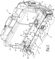
- an automotive vehicle 8 (shown representatively by dashed-box 8) has an expandable underseat storage compartment 24 between a vehicle rear seat assembly 12 and a vehicle floor 14.
- vehicle rear seat assembly 12 is a seat assembly disposed rearward of a front seat assembly of the vehicle and need not be the most rearward seat assembly in the vehicle, such as in the case where the vehicle has a middle row seat assembly behind the front seat assembly and a back seat assembly behind of the middle row seat assembly.
- references to right, left, front, forward, rear, etc. are with respect an occupant of the vehicle facing forward.
- the seat assembly 12 includes right and left seat bottoms 16a, 16b, respectively, (together known as a set of seat bottoms 16) and an elongated seat support member 18 having a middle portion 33, a middle pedestal 210, and right and left end pedestals 32a, 32b, respectively, at right and left ends 31a, 31b, respectively, of middle portion 33.
- Middle portion 33 extends laterally across vehicle 8 and right and left end pedestals 32a, 32b extend longitudinally forward from respective right and left opposed ends 31a, 31b of middle portion 33.
- Right and left bracket plates 20a, 20b, respectively, are affixed to right and left end pedestals 32a, 32b.
- a front panel assembly 22 extends laterally across vehicle 8 in front of the right and left bracket plates 20a, 20b and right and left end pedestals 32a, 32b.
- Elongated seat support member 18, right and left bracket plates 20a, 20b, and front panel assembly 22 cooperate to provide an expandable underseat storage compartment assembly 10.
- the elongated seat support member 18, the right and left bracket plates 20a, 20b, and the front panel assembly 22 cooperate to define storage compartment 24 wherein middle portion 33 of the elongated seat support member 18 defines a rear side 200 of the storage compartment 24, right and left end pedestals 32a, 32b of the elongated seat support member and right and left bracket plates 20a, 20b define right and left sides 202a, 202b of storage compartment 24 and front panel assembly 22 defines a front side 204 of storage compartment 24.
- the right seat bottom 16a of the vehicle seat assembly 12 is coupled to the elongated seat support member 18 via a pair of right runner assemblies 26 while a left seat bottom 16b of the vehicle seat assembly 12 is positioned adjacently to the right seat bottom 16a and coupled to the elongated seat support member 18 via a pair of left runner assemblies 28.
- the right and left seat bottoms 16a, 16b are independently rotatable relative to the elongated seat support member 18 between a seated state ( Figure 6 ) and a lifted state ( Figures 2-5 and 7 ).
- the right and left seat bottoms 16a, 16B when in the seated position provide a top cover over at least a portion of portion of storage compartment 24.
- the front panel assembly 22 is movable between a retracted position in which the front side 204 of storage compartment 24 is adjacent fronts sides 208a, 208b of the right and left end pedestals 32a, 32b of elongated seat support member 18 and an extended position in which the front side 204 of storage compartment 24 is spaced forwardly from the front sides 208a, 208b of right and left end pedestals 32a, 32b of elongated seat support member 18.
- the front side 204 of storage compartment 24 is at or near a front end 30 of the set of seat bottoms 16 when the seat of seat bottoms 16 are in a seated position ( Figure 6 ).
- a storage area 25 of storage compartment 24 is larger than when front assembly 22 is in the retracted position.
- the elongated seat support member 18 extends upwardly from the vehicle floor 14 and in addition to right and left end pedestals 32a, 32b, middle portion 33, and middle pedestal 210, also includes a pair of sloped surfaces 34.
- End pedestals 32a, 32b include respective vertical inner walls 36a, 36b and respective vertical outer walls 38a, 38b.
- the pair of sloped surfaces 34 are between the right and left end pedestals 32a, 32b and are separated by the middle pedestal 210.
- the pair of sloped surfaces 34 also extend from a top edge 212 of the elongated seat support member 18 to the vehicle floor 14, and are so shaped to accommodate contours of the vehicle floor 14.
- the right and left bracket plates 20a, 2b are fixedly mounted to the vehicle floor 14 at right and left end pedestals 32a, 32b of the elongated seat support member 18.
- the right and left bracket plates 20a, 20b are adjacent to corresponding right and left outer walls 38a, 38b of the respective right and left end pedestals 32a, 32b of elongated seat support member 18 and attached to the vehicle floor 14 via fasteners (not shown).
- each right and left bracket plate 20a, 20b is attached to a corresponding right and left outer wall 38a, 38b of the corresponding right and left end pedestals 32a, 32b, instead of, or in addition to, being attached to the vehicle floor 14.
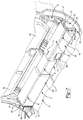
- Each bracket plate 20a, 20b cooperates with the corresponding right and left end pedestal 32a, 32b of the elongated seat support member 18 to define right and left recesses 46a, 46b ( Figures 4 and 5 ).
- Each bracket plate 20a, 20b includes an attachment section 47 and a pivot section 49.
- the attachment section 47 attaches the respective bracket plate 20a, 20b to the vehicle floor 14 and includes a wall 48 having a partition 50, an attachment surface 52, and an elongated edge 54 extending therefrom.
- the partition 50 extends outwardly from an upper portion of the wall 48 and defines an end of the recess 46.
- the attachment surface 52 extends outwardly from a lower portion of the wall 48 and is parallel to the vehicle floor 14.
- a fastener (not shown) extends through an aperture (not shown) formed in the attachment surface 52 so as to attach the respective bracket plate 20a, 20b to the vehicle floor 14.
- the elongated edge 54 extends outwardly from the upper portion of the wall 48 to the lower portion thereof.
- the elongated edge 54 has a lower surface 56 that is parallel to the vehicle floor 14.
- a fastener (not shown) illustratively extends through the lower surface 56 to further attach and secure the respective bracket plate 20a, 20b to the vehicle floor 14.
- the pivot section 49 includes a pivot aperture 57 extending therethrough at a lower end thereof.
- the front panel assembly 22 is rotatably coupled to the right and left bracket plates 20a, 20b.
- the front panel assembly 22 includes right and left triangular-shaped cover plates 58a, 58b, a primary panel 86 and a secondary panel 88 with the primary panel 86 and the secondary panel 88 hingedly attached to each other along respective lateral edges 87, 89 via a pair of hinge assemblies 90.
- the right cover plate 58a is rotatably attached to right bracket plate 20a and the left cover plate 58b is rotatably attached to the left bracket plate 20b.
- Each cover plate 58a, 58b includes a wall 62 and a flange 64. As shown in Figure 1 , the wall 62 includes an aperture 65 extending therethrough at a lower end thereof.
- the aperture 65 is aligned with a respective aperture 57 of the pivot section 49 of the respective right or left bracket plate 20a, 20b such that a fastener 68a (e.g., bolt, rivet, etc.) of a fastener assembly 68 (composed of the fastener 68a and a washer 68b) extends through both apertures 57, 65, thereby, permitting the right or left cover plate 58a, 58b to pivot relative to the corresponding right or left bracket plate 20a, 20b.
- the flange 64 extends perpendicularly from a periphery of the wall 62 and includes an outer flange section 70, a middle flange section 72, and an inner flange section 74.
- the outer flange section 70 is parallel to the inner flange section 74 and perpendicular to the middle flange section 72.
- the outer flange section 70 includes an inside surface (not shown), an outer surface 78, and a plurality of apertures 80 ( Figure 1 ) extending therethrough.
- the middle flange section 72 is positioned between the outer flange section 70 and the inner flange section 74 and includes an outer surface 82 and an inside surface (not shown).
- the front panel assembly 22 is disposed beneath the set of seat bottoms 16.
- the primary panel 86 is substantially rectangular and includes a primary handle 94 near a middle portion thereof that protrudes toward the secondary panel 88 when the front panel assembly 22 is in the retracted position ( Figures 2 and 3 ).
- the primary panel 86 also includes a plurality of apertures 96 at each right and left end 98a, 98b thereof. Each right and left end 98a, 98b of the primary panel 86 abuts against a corresponding inside surface (not shown) of the outer flange section 70 such that the apertures 96 align with a corresponding aperture 80 of the outer flange section 70.
- fasteners 100 extend through apertures 80, 96 of the outer flange section 70 and the primary panel 86, respectively, such that the primary panel 86 and the bracket plates 20a, 20b are secured to each other.
- a slot 102 is disposed in a recess 104 formed in a surface 106 of the primary panel 86.
- the secondary panel 88 is substantially rectangular and includes a secondary handle 108 near a middle portion thereof that protrudes toward the elongated seat support member 18 when the front panel assembly 22 is in the retracted position.
- the secondary panel 88 also includes an oval-shaped slot 110 adjacent to the secondary handle 108 that is aligned with the slot 102 of the primary panel 86.
- a latch mechanism 23 is coupled to the middle pedestal 210 of the elongated seat support member 18 and includes an L-shaped bracket plate 112 and a lever 114.
- the L-shaped bracket plate 112 is disposed inside of the middle pedestal 210 of the elongated seat support member 18 such that it is concealed from users of the expandable underseat storage compartment assembly 10.
- the lever 114 is movably attached to the bracket plate 112 and includes an oval-shaped aperture 116 the allows the user (not shown) to conveniently move the lever between a locked state ( Figure 2 ) in which the lever 114 restricts the front panel assembly 22 from being moved to the extended position and an unlocked state ( Figure 3 ) in which the panel assembly 22 is allowed to move to the extended position.
- the lever 114 When in the locked state, the lever 114 extends through the slots 110, 102 of the secondary panel 88 and the primary panel 86, respectively, and is received in the recess 104 formed in the surface 106 of the primary panel 86 ( Figure 2 ).
- FIG. 1-7 operation of the front panel assembly 22 will be described in more detail.
- the front panel assembly 22 When the front panel assembly 22 is in the retracted position and at least one seat bottom (16a and/or 16b) of the set of seat bottoms 16 is in the lifted state ( Figure 2 ), the user is able to access the storage compartment 24 to store various items therein.
- storage space 25 of the storage compartment 24 is defined by the elongated seat support member 18, the right and left bracket plates 20a, 20b, and the primary panel 86 of the front panel assembly 22 ( Figures 2 and 3 ).
- the user grasps and moves the lever 114 from the locked state to the unlocked state.
- the user then rotates the front panel assembly 22 ninety degrees counter-clockwise ( Figure 4 ).
- the right and left cover plates 58a, 58b rotate relative to the corresponding right and left bracket plates 20a, 20b which are pulled out from the recesses 46 ( Figure 4 ).
- Each right and left end 118a, 118b of the secondary panel 88 includes one or more magnetic elements 120 attached thereto ( Figure 4 ) and the right and left cover plates 58a, 58b have corresponding magnetic elements 121 which cooperate to magnetically attract each other such that the secondary panel 88 is retained against the inside surface (not shown) of the middle flange section 72 of the cover plate 58 when the panel assembly 22 is in the extended position.
- the magnetic elements 120, 121 are both magnets or either magnetic element 120 and the corresponding magnetic element 121 is a magnet and the other is made of ferromagnetic material.
- cover plates 58a, 58B are made of as ferromagnetic material providing the magnetic element 121 without having a separate magnetic element as magnetic element 121.
- the at least one seat bottom (16a and/or 16b) is rotated to the seated state and the secondary panel 88, the right and left cover plates 58a, 58b, the middle portion 33 and the right and left end pedestals 32a, 32b of elongated seat support member 18 and the right and left bracket plates 20a, 20b define the storage area 25 of storage compartment 24 extending from the rear end 29 of the set of seat bottoms 16 to the front end 30 thereof.
- secondary panel 88 provides a top cover that covers at least a portion of an opening of storage compartment 24.
- the user rotates the front panel assembly 22 ninety degrees clockwise after the front panel assembly has been rotated to the extended position and the secondary panel 88 has been rotated so that it is perpendicular to the primary panel.
- the right and left plates 58a, 58b rotate relative to the respective right and left bracket plates 20a, 20b and are received in the corresponding right and left recesses 46a, 46b ( Figure 7 ).
- the secondary panel 88 acts as a top to cover at least a portion of an opening (not shown) in the storage compartment 24 ( Figure 7 ).
- a secondary panel 188 that is a variation of secondary panel 88 is shown. Except as discussed below, the structure and function of the secondary panel 188 is similar or identical to that of the secondary panel 88.
- the secondary panel 188 is substantially rectangular and includes a secondary handle 190 near a middle portion thereof, an oval-shaped slot (not shown) adjacent to the secondary handle 190, and a pair of rectangular dividers 192.
- Each divider 192 has a detent 193 (only one of which is shown in Figure 8 ) that allows the divider 192 to move between a retracted state in which the divider 192 is received in a recess 194 formed in a corresponding end 196 of the secondary panel 188 and an extended state in which the divider 192 extends perpendicular to the recess 194 ( Figure 8 ). In this way, when the front panel assembly 22 is moved to the extended position as described above, the dividers 192 are extended such that sub-compartments 198 are formed in the storage compartment 24.
Landscapes
- Engineering & Computer Science (AREA)
- Mechanical Engineering (AREA)
- Aviation & Aerospace Engineering (AREA)
- Transportation (AREA)
- Seats For Vehicles (AREA)
- Vehicle Step Arrangements And Article Storage (AREA)
Claims (9)
- Véhicule automobile (8) comportant un ensemble de rangement de sous-siège extensible (10), comprenant :un plancher (14) et au moins un ensemble siège arrière (12) ;un élément de support de siège allongé (18) qui s'étend vers le haut depuis le plancher de la carrosserie de véhicule et supporte l'ensemble siège arrière, l'élément de support de siège allongé comportant une partie médiane (33) qui s'étend latéralement à travers le véhicule et des socles d'extrémité droite et gauche (32a, 32b) qui s'étendent longitudinalement vers l'avant depuis des extrémités droite et gauche (31a, 31b) de la partie médiane ;des plaques d'appui droite et gauche (20a, 20b) disposées de manière adjacente à des parois extérieures (38a, 38b) des socles d'extrémité droite et gauche, les plaques d'appui droite et gauche étant fixées à demeure à l'un ou les deux parmi le plancher de véhicule et un respectif des socles d'extrémité droite et gauche de l'élément de support de siège allongé ;un ensemble panneau avant (22) s'étendant latéralement à travers le véhicule devant les socles d'extrémité droite et gauche et accouplé en rotation aux plaques d'appui droite et gauche ;l'élément de support de siège allongé, les plaques d'appui droite et gauche et l'ensemble panneau avant définissant une zone de rangement (25) d'un compartiment de rangement (24) de l'ensemble de rangement de sous-siège dans lequel la partie médiane de l'élément de support de siège allongé définit un côté arrière (200) du compartiment de rangement, les socles d'extrémité droite et gauche et les plaques d'appui droite et gauche définissent des côtés droit et gauche (202a, 202b) du compartiment de rangement et l'ensemble panneau avant définit un côté avant (204) du compartiment de rangement ;l'ensemble panneau avant est mobile entre une position étendue et une position rétractée dans lequel lorsque l'ensemble panneau avant est dans la position étendue la zone de rangement du compartiment de rangement est plus grande que lorsque l'ensemble panneau avant est dans la position rétractée, l'ensemble panneau avant comportant un panneau primaire (86) et un panneau secondaire (88) fixés de manière articulée l'un à l'autre le long de bords latéraux (87, 89) respectifs ;caractérisé en ce que lorsque l'ensemble panneau avant (22) est dans la position rétractée les panneaux primaire et secondaire (86, 88) reposent l'un contre l'autre dans une position verticale avec les bords latéraux (87, 89) fixés de manière articulée des panneaux primaire et secondaire qui sont les bords latéraux supérieurs des panneaux primaire et secondaire et les panneaux primaire et secondaire sont adjacents aux bords avant des socles d'extrémité droite et gauche (32a, 32b) de l'élément de support de siège allongé (18) et les panneaux primaire et secondaire verticaux définissent le côté avant (204) du compartiment de rangement (24) avec la zone de rangement définie par le panneau primaire et l'élément de support de siège allongé ; etlorsque l'ensemble panneau avant est déplacé jusqu'à la position étendue, le panneau primaire (86) est tourné vers l'avant et vers le bas et s'étend vers l'avant depuis les socles d'extrémité droite et gauche (32a, 32b) et le panneau secondaire (88) est tourné vers l'avant et vers le haut de telle sorte qu'il s'étend verticalement vers le haut depuis le panneau primaire dans lequel le panneau secondaire vertical lorsque l'ensemble panneau avant est dans la position étendue est espacé vers l'avant d'une position des panneaux primaire et secondaire verticaux lorsque l'ensemble panneau avant est dans la position rétractée et la zone de rangement est définie par le panneau secondaire vertical (88), les plaques d'appui droite et gauche (20a, 20b) et l'élément de support de siège allongé (18).
- Véhicule automobile selon la revendication 1 dans lequel l'élément de support allongé et la plaque d'appui droite coopèrent pour définir un évidement droit (46a) et l'élément de support allongé et la plaque d'appui gauche coopèrent pour définir un évidement gauche (46b) dans lequel lorsque l'ensemble panneau avant est dans la position rétractée une plaque de protection droite (58a) est reçue dans l'évidement droit et une plaque de protection gauche (58b) est reçue dans l'évidement gauche.
- Véhicule automobile selon la revendication 2 dans lequel la plaque de protection droite est accouplée en rotation à la plaque d'appui droite et la plaque de protection gauche est accouplée en rotation à la plaque d'appui gauche.
- Véhicule automobile selon la revendication 3 dans lequel chaque plaque de protection comporte une bride (64) s'étendant depuis une périphérie de cette plaque de protection et une extrémité droite (98a) du panneau primaire est accouplée à la bride de la plaque de protection droite et une extrémité gauche (98b) du panneau primaire est accouplée à la bride de la plaque de protection gauche.
- Véhicule automobile selon la revendication 4 dans lequel lorsque l'ensemble panneau avant est dans la position étendue une extrémité droite du panneau secondaire vient buter contre la bride de la plaque de protection droite et une extrémité gauche du panneau secondaire vient buter contre la bride de la plaque de protection gauche.
- Véhicule automobile selon la revendication 5 dans lequel chacune des extrémités droite et gauche du panneau secondaire comporte au moins un élément magnétique (120) et les plaques de protection droite et gauche comportent au moins un élément magnétique (121) correspondant dans lequel lorsque l'ensemble panneau avant est dans la position étendue, les éléments magnétiques des extrémités droite et gauche du panneau secondaire entrent magnétiquement en prise avec des éléments magnétiques correspondants des plaques de protection droite et gauche pour maintenir l'ensemble panneau avant dans la position étendue.
- Véhicule automobile selon la revendication 1 dans lequel l'ensemble panneau avant est configuré pour être tourné de la position étendue à la position rétractée avec le panneau secondaire s'étendant horizontalement vers l'arrière depuis le bord latéral supérieur du panneau primaire de telle sorte que le panneau secondaire fournit une protection supérieure par-dessus au moins une partie du compartiment de rangement.
- Véhicule automobile selon la revendication 1 dans lequel le panneau secondaire comporte au moins un séparateur (192) et un évidement (194) correspondant dans lequel est reçu le séparateur, le séparateur étant fixé de manière pivotante au panneau secondaire et lorsque l'ensemble panneau avant est dans la position étendue, le séparateur peut pivoter d'une position rétractée où il est reçu dans l'évidement correspondant à une position étendue où il s'étend vers l'extérieur depuis l'évidement et lorsque le séparateur est dans la position étendue il sépare le compartiment de rangement en sous-compartiments (198).
- Véhicule automobile selon la revendication 1, dans lequel l'un parmi l'élément de support allongé et l'ensemble panneau avant comporte un mécanisme de verrouillage (23) et l'autre parmi l'élément de support allongé et l'ensemble panneau avant comporte un élément de verrouillage, l'élément de verrouillage pouvant venir en prise et être libéré du mécanisme de verrouillage, le mécanisme de verrouillage et l'élément de verrouillage maintenant l'ensemble panneau avant dans la position rétractée lorsque le mécanisme de verrouillage est en prise avec l'élément de verrouillage et lorsque l'élément de verrouillage est libéré du mécanisme de verrouillage l'ensemble panneau avant est mobile jusqu'à la position étendue.
Applications Claiming Priority (2)
| Application Number | Priority Date | Filing Date | Title |
|---|---|---|---|
| US15/689,537 US10137841B1 (en) | 2017-08-29 | 2017-08-29 | Automotive vehicle with expandable underseat storage compartment |
| PCT/US2018/048132 WO2019046187A1 (fr) | 2017-08-29 | 2018-08-27 | Véhicule automobile avec compartiment de rangement de sous-siège extensible |
Publications (2)
| Publication Number | Publication Date |
|---|---|
| EP3676129A1 EP3676129A1 (fr) | 2020-07-08 |
| EP3676129B1 true EP3676129B1 (fr) | 2021-07-14 |
Family
ID=63528937
Family Applications (1)
| Application Number | Title | Priority Date | Filing Date |
|---|---|---|---|
| EP18766471.9A Active EP3676129B1 (fr) | 2017-08-29 | 2018-08-27 | Véhicule automobile avec compartiment de rangement de sous-siège extensible |
Country Status (6)
| Country | Link |
|---|---|
| US (1) | US10137841B1 (fr) |
| EP (1) | EP3676129B1 (fr) |
| CN (1) | CN111278682B (fr) |
| CA (1) | CA3074427A1 (fr) |
| MX (1) | MX2020002246A (fr) |
| WO (1) | WO2019046187A1 (fr) |
Families Citing this family (9)
| Publication number | Priority date | Publication date | Assignee | Title |
|---|---|---|---|---|
| US20190176675A1 (en) * | 2017-12-13 | 2019-06-13 | Ford Global Technologies, Llc | Motor vehicle equipped with a strongbox and method for securing a valuable item in a motor vehicle |
| US11834005B2 (en) | 2018-08-28 | 2023-12-05 | Abc Technologies Inc. | Cargo containment systems |
| US10926717B2 (en) * | 2018-10-24 | 2021-02-23 | Fca Us Llc | Vehicle with integrated portable wireless speaker system |
| US10933923B1 (en) * | 2019-03-27 | 2021-03-02 | Adam J. Wurzer | Horizontal cabinet kit in sleeper cab of a truck |
| FR3116478B1 (fr) * | 2020-11-24 | 2024-06-21 | Renault Sas | Véhicule doté d’une banquette arrière apte à former des espaces de rangement |
| US12187230B1 (en) * | 2021-01-21 | 2025-01-07 | Robert Squicciarini | Center console to cargo area storage system for a sport utility vehicle of emergency responders |
| US11897424B2 (en) | 2021-05-07 | 2024-02-13 | Abc Technologies Inc. | Front trunk storage system |
| US12103496B2 (en) * | 2021-10-29 | 2024-10-01 | Nissan North America, Inc. | Storage compartments in vehicles |
| US12594891B2 (en) | 2022-12-19 | 2026-04-07 | Nissan North America, Inc. | Under-seat storage system for a vehicle |
Family Cites Families (18)
| Publication number | Priority date | Publication date | Assignee | Title |
|---|---|---|---|---|
| US5957521A (en) * | 1995-03-22 | 1999-09-28 | Schlachter; Bradley S. | Underseat storage enclosure |
| US6074000A (en) | 1996-10-22 | 2000-06-13 | Borneman Products, Inc. | Vehicle seat and receptacle |
| US6752443B1 (en) * | 1999-06-07 | 2004-06-22 | Johnson Controls Technology Company | Load floor system |
| US6644523B1 (en) | 2001-09-14 | 2003-11-11 | James R. Salas | Storage device |
| US7341301B1 (en) | 2006-12-22 | 2008-03-11 | Chrysler Llc | Seat assembly having a storage system |
| FR2910859B1 (fr) | 2007-01-02 | 2009-08-28 | Airbus Groupement D Interet Ec | Dispositif de rangement de bagages pour vehicule de transport en commun |
| DE102007020190A1 (de) | 2007-04-28 | 2008-10-30 | Ford Global Technologies, LLC, Dearborn | Fahrzeugsitz mit Staufach |
| CN201086684Y (zh) * | 2007-08-30 | 2008-07-16 | 福特全球技术公司 | 放置千斤顶和工具的容器及用于放置该容器的沟槽结构 |
| US8632113B2 (en) * | 2011-09-09 | 2014-01-21 | Chrysler Group Llc | Stowable seat arrangement for a motor vehicle |
| US8770661B2 (en) * | 2012-06-29 | 2014-07-08 | Ford Global Technologies, Llc | Configurable underseat storage feature |
| US9016749B2 (en) * | 2013-09-24 | 2015-04-28 | Ford Global Technologies, Llc | Collapsible rear seat storage assembly |
| US9174582B2 (en) * | 2013-12-12 | 2015-11-03 | Ford Global Technologies, Llc | Cargo area retention system |
| CN203739768U (zh) * | 2013-12-26 | 2014-07-30 | 比亚迪股份有限公司 | 用于汽车的储物盒和具有其的汽车 |
| US9481309B2 (en) * | 2014-01-16 | 2016-11-01 | Ford Global Technologies, Llc | Vehicle seat item retention system |
| US9481310B2 (en) * | 2015-01-09 | 2016-11-01 | Nissan North America, Inc. | Vehicle storage structure |
| US10710509B2 (en) * | 2015-09-16 | 2020-07-14 | Ford Global Technologies, Llc | Collapsible storage bin for a motor vehicle |
| JP6667947B2 (ja) * | 2015-12-21 | 2020-03-18 | ダイハツ工業株式会社 | シートのアンダートレイ支持構造 |
| US9873383B1 (en) * | 2017-03-28 | 2018-01-23 | Fca Us Llc | Deployable under-seat cargo assembly |
-
2017
- 2017-08-29 US US15/689,537 patent/US10137841B1/en active Active
-
2018
- 2018-08-27 CA CA3074427A patent/CA3074427A1/fr not_active Abandoned
- 2018-08-27 WO PCT/US2018/048132 patent/WO2019046187A1/fr not_active Ceased
- 2018-08-27 EP EP18766471.9A patent/EP3676129B1/fr active Active
- 2018-08-27 MX MX2020002246A patent/MX2020002246A/es unknown
- 2018-08-27 CN CN201880069851.8A patent/CN111278682B/zh active Active
Also Published As
| Publication number | Publication date |
|---|---|
| EP3676129A1 (fr) | 2020-07-08 |
| WO2019046187A1 (fr) | 2019-03-07 |
| CN111278682B (zh) | 2023-04-18 |
| MX2020002246A (es) | 2021-02-09 |
| CA3074427A1 (fr) | 2019-03-07 |
| CN111278682A (zh) | 2020-06-12 |
| US10137841B1 (en) | 2018-11-27 |
Similar Documents
| Publication | Publication Date | Title |
|---|---|---|
| EP3676129B1 (fr) | Véhicule automobile avec compartiment de rangement de sous-siège extensible | |
| US7533918B2 (en) | Console storage enclosure | |
| EP3044038B1 (fr) | Console de véhicule possédant une glissière servant à déplacer une porte coulissante entre plusieurs positions | |
| CA2245311C (fr) | Console centrale coulissante a plateau reglable | |
| US5632520A (en) | Cargo-restraining apparatus for motor vehicle | |
| US7748762B2 (en) | Vehicle console assembly | |
| US6386612B2 (en) | Under seat storage system | |
| DE102018102657B4 (de) | Fahrzeugtüranordnung mit einem lagerbehälter, der in längsrichtung verschiebbar ist | |
| US20060261621A1 (en) | A modular vehicle interior component system and release latch mechanism for use with the system | |
| EP3112218B1 (fr) | Coffre de toit pour véhicules | |
| US9873383B1 (en) | Deployable under-seat cargo assembly | |
| US10427612B2 (en) | Vehicle door | |
| US20020139824A1 (en) | Device comprising a removable sliding central console | |
| US9469349B1 (en) | Vehicle floor assembly | |
| US9457724B2 (en) | Cargo cover assemblies and vehicles incorporating the same | |
| MX2014014020A (es) | Ocultador de separacion de cubiertas tonneau para asientos traseros ajustables. | |
| CA2434056A1 (fr) | Plateau de tiroir coulissant et verrouillable | |
| US4256340A (en) | Lockable storage compartment and seat for vehicles | |
| US9643518B2 (en) | Motor vehicle seat comprising a seatback part with a detachable part provided with storage means | |
| US20200130590A1 (en) | Removably secured storage bin for specialized vehicle hardware | |
| US9517710B2 (en) | Motor vehicle comprising a seat having a detachable sitting part for freeing access to a recess in the internal structure of the vehicle | |
| KR20140112859A (ko) | 자동차의 물건 수납장치와 이를 이용한 밴형 자동차의 격벽 | |
| US6024397A (en) | Rotating seat/storage unit | |
| US20200331397A1 (en) | Lockable interior storage volume within a passenger compartment of a vehicle | |
| US20160229348A1 (en) | Interior trim assembly for a vehicle |
Legal Events
| Date | Code | Title | Description |
|---|---|---|---|
| STAA | Information on the status of an ep patent application or granted ep patent |
Free format text: STATUS: UNKNOWN |
|
| STAA | Information on the status of an ep patent application or granted ep patent |
Free format text: STATUS: THE INTERNATIONAL PUBLICATION HAS BEEN MADE |
|
| PUAI | Public reference made under article 153(3) epc to a published international application that has entered the european phase |
Free format text: ORIGINAL CODE: 0009012 |
|
| STAA | Information on the status of an ep patent application or granted ep patent |
Free format text: STATUS: REQUEST FOR EXAMINATION WAS MADE |
|
| 17P | Request for examination filed |
Effective date: 20200306 |
|
| AK | Designated contracting states |
Kind code of ref document: A1 Designated state(s): AL AT BE BG CH CY CZ DE DK EE ES FI FR GB GR HR HU IE IS IT LI LT LU LV MC MK MT NL NO PL PT RO RS SE SI SK SM TR |
|
| AX | Request for extension of the european patent |
Extension state: BA ME |
|
| DAV | Request for validation of the european patent (deleted) | ||
| DAX | Request for extension of the european patent (deleted) | ||
| GRAP | Despatch of communication of intention to grant a patent |
Free format text: ORIGINAL CODE: EPIDOSNIGR1 |
|
| STAA | Information on the status of an ep patent application or granted ep patent |
Free format text: STATUS: GRANT OF PATENT IS INTENDED |
|
| INTG | Intention to grant announced |
Effective date: 20210211 |
|
| GRAS | Grant fee paid |
Free format text: ORIGINAL CODE: EPIDOSNIGR3 |
|
| GRAA | (expected) grant |
Free format text: ORIGINAL CODE: 0009210 |
|
| STAA | Information on the status of an ep patent application or granted ep patent |
Free format text: STATUS: THE PATENT HAS BEEN GRANTED |
|
| AK | Designated contracting states |
Kind code of ref document: B1 Designated state(s): AL AT BE BG CH CY CZ DE DK EE ES FI FR GB GR HR HU IE IS IT LI LT LU LV MC MK MT NL NO PL PT RO RS SE SI SK SM TR |
|
| REG | Reference to a national code |
Ref country code: GB Ref legal event code: FG4D |
|
| REG | Reference to a national code |
Ref country code: IE Ref legal event code: FG4D |
|
| REG | Reference to a national code |
Ref country code: DE Ref legal event code: R096 Ref document number: 602018020168 Country of ref document: DE |
|
| REG | Reference to a national code |
Ref country code: AT Ref legal event code: REF Ref document number: 1410391 Country of ref document: AT Kind code of ref document: T Effective date: 20210815 |
|
| REG | Reference to a national code |
Ref country code: LT Ref legal event code: MG9D |
|
| REG | Reference to a national code |
Ref country code: NL Ref legal event code: MP Effective date: 20210714 |
|
| REG | Reference to a national code |
Ref country code: AT Ref legal event code: MK05 Ref document number: 1410391 Country of ref document: AT Kind code of ref document: T Effective date: 20210714 |
|
| PG25 | Lapsed in a contracting state [announced via postgrant information from national office to epo] |
Ref country code: PT Free format text: LAPSE BECAUSE OF FAILURE TO SUBMIT A TRANSLATION OF THE DESCRIPTION OR TO PAY THE FEE WITHIN THE PRESCRIBED TIME-LIMIT Effective date: 20211115 Ref country code: NO Free format text: LAPSE BECAUSE OF FAILURE TO SUBMIT A TRANSLATION OF THE DESCRIPTION OR TO PAY THE FEE WITHIN THE PRESCRIBED TIME-LIMIT Effective date: 20211014 Ref country code: NL Free format text: LAPSE BECAUSE OF FAILURE TO SUBMIT A TRANSLATION OF THE DESCRIPTION OR TO PAY THE FEE WITHIN THE PRESCRIBED TIME-LIMIT Effective date: 20210714 Ref country code: AT Free format text: LAPSE BECAUSE OF FAILURE TO SUBMIT A TRANSLATION OF THE DESCRIPTION OR TO PAY THE FEE WITHIN THE PRESCRIBED TIME-LIMIT Effective date: 20210714 Ref country code: BG Free format text: LAPSE BECAUSE OF FAILURE TO SUBMIT A TRANSLATION OF THE DESCRIPTION OR TO PAY THE FEE WITHIN THE PRESCRIBED TIME-LIMIT Effective date: 20211014 Ref country code: LT Free format text: LAPSE BECAUSE OF FAILURE TO SUBMIT A TRANSLATION OF THE DESCRIPTION OR TO PAY THE FEE WITHIN THE PRESCRIBED TIME-LIMIT Effective date: 20210714 Ref country code: RS Free format text: LAPSE BECAUSE OF FAILURE TO SUBMIT A TRANSLATION OF THE DESCRIPTION OR TO PAY THE FEE WITHIN THE PRESCRIBED TIME-LIMIT Effective date: 20210714 Ref country code: SE Free format text: LAPSE BECAUSE OF FAILURE TO SUBMIT A TRANSLATION OF THE DESCRIPTION OR TO PAY THE FEE WITHIN THE PRESCRIBED TIME-LIMIT Effective date: 20210714 Ref country code: ES Free format text: LAPSE BECAUSE OF FAILURE TO SUBMIT A TRANSLATION OF THE DESCRIPTION OR TO PAY THE FEE WITHIN THE PRESCRIBED TIME-LIMIT Effective date: 20210714 Ref country code: FI Free format text: LAPSE BECAUSE OF FAILURE TO SUBMIT A TRANSLATION OF THE DESCRIPTION OR TO PAY THE FEE WITHIN THE PRESCRIBED TIME-LIMIT Effective date: 20210714 Ref country code: HR Free format text: LAPSE BECAUSE OF FAILURE TO SUBMIT A TRANSLATION OF THE DESCRIPTION OR TO PAY THE FEE WITHIN THE PRESCRIBED TIME-LIMIT Effective date: 20210714 |
|
| PG25 | Lapsed in a contracting state [announced via postgrant information from national office to epo] |
Ref country code: PL Free format text: LAPSE BECAUSE OF FAILURE TO SUBMIT A TRANSLATION OF THE DESCRIPTION OR TO PAY THE FEE WITHIN THE PRESCRIBED TIME-LIMIT Effective date: 20210714 Ref country code: LV Free format text: LAPSE BECAUSE OF FAILURE TO SUBMIT A TRANSLATION OF THE DESCRIPTION OR TO PAY THE FEE WITHIN THE PRESCRIBED TIME-LIMIT Effective date: 20210714 Ref country code: GR Free format text: LAPSE BECAUSE OF FAILURE TO SUBMIT A TRANSLATION OF THE DESCRIPTION OR TO PAY THE FEE WITHIN THE PRESCRIBED TIME-LIMIT Effective date: 20211015 |
|
| REG | Reference to a national code |
Ref country code: CH Ref legal event code: PL |
|
| REG | Reference to a national code |
Ref country code: DE Ref legal event code: R097 Ref document number: 602018020168 Country of ref document: DE |
|
| REG | Reference to a national code |
Ref country code: BE Ref legal event code: MM Effective date: 20210831 |
|
| PG25 | Lapsed in a contracting state [announced via postgrant information from national office to epo] |
Ref country code: LI Free format text: LAPSE BECAUSE OF NON-PAYMENT OF DUE FEES Effective date: 20210831 Ref country code: DK Free format text: LAPSE BECAUSE OF FAILURE TO SUBMIT A TRANSLATION OF THE DESCRIPTION OR TO PAY THE FEE WITHIN THE PRESCRIBED TIME-LIMIT Effective date: 20210714 Ref country code: CH Free format text: LAPSE BECAUSE OF NON-PAYMENT OF DUE FEES Effective date: 20210831 |
|
| PLBE | No opposition filed within time limit |
Free format text: ORIGINAL CODE: 0009261 |
|
| STAA | Information on the status of an ep patent application or granted ep patent |
Free format text: STATUS: NO OPPOSITION FILED WITHIN TIME LIMIT |
|
| PG25 | Lapsed in a contracting state [announced via postgrant information from national office to epo] |
Ref country code: SM Free format text: LAPSE BECAUSE OF FAILURE TO SUBMIT A TRANSLATION OF THE DESCRIPTION OR TO PAY THE FEE WITHIN THE PRESCRIBED TIME-LIMIT Effective date: 20210714 Ref country code: SK Free format text: LAPSE BECAUSE OF FAILURE TO SUBMIT A TRANSLATION OF THE DESCRIPTION OR TO PAY THE FEE WITHIN THE PRESCRIBED TIME-LIMIT Effective date: 20210714 Ref country code: RO Free format text: LAPSE BECAUSE OF FAILURE TO SUBMIT A TRANSLATION OF THE DESCRIPTION OR TO PAY THE FEE WITHIN THE PRESCRIBED TIME-LIMIT Effective date: 20210714 Ref country code: MC Free format text: LAPSE BECAUSE OF FAILURE TO SUBMIT A TRANSLATION OF THE DESCRIPTION OR TO PAY THE FEE WITHIN THE PRESCRIBED TIME-LIMIT Effective date: 20210714 Ref country code: LU Free format text: LAPSE BECAUSE OF NON-PAYMENT OF DUE FEES Effective date: 20210827 Ref country code: EE Free format text: LAPSE BECAUSE OF FAILURE TO SUBMIT A TRANSLATION OF THE DESCRIPTION OR TO PAY THE FEE WITHIN THE PRESCRIBED TIME-LIMIT Effective date: 20210714 Ref country code: CZ Free format text: LAPSE BECAUSE OF FAILURE TO SUBMIT A TRANSLATION OF THE DESCRIPTION OR TO PAY THE FEE WITHIN THE PRESCRIBED TIME-LIMIT Effective date: 20210714 Ref country code: AL Free format text: LAPSE BECAUSE OF FAILURE TO SUBMIT A TRANSLATION OF THE DESCRIPTION OR TO PAY THE FEE WITHIN THE PRESCRIBED TIME-LIMIT Effective date: 20210714 |
|
| 26N | No opposition filed |
Effective date: 20220419 |
|
| PG25 | Lapsed in a contracting state [announced via postgrant information from national office to epo] |
Ref country code: IE Free format text: LAPSE BECAUSE OF NON-PAYMENT OF DUE FEES Effective date: 20210827 Ref country code: BE Free format text: LAPSE BECAUSE OF NON-PAYMENT OF DUE FEES Effective date: 20210831 |
|
| PG25 | Lapsed in a contracting state [announced via postgrant information from national office to epo] |
Ref country code: CY Free format text: LAPSE BECAUSE OF FAILURE TO SUBMIT A TRANSLATION OF THE DESCRIPTION OR TO PAY THE FEE WITHIN THE PRESCRIBED TIME-LIMIT Effective date: 20210714 |
|
| PG25 | Lapsed in a contracting state [announced via postgrant information from national office to epo] |
Ref country code: HU Free format text: LAPSE BECAUSE OF FAILURE TO SUBMIT A TRANSLATION OF THE DESCRIPTION OR TO PAY THE FEE WITHIN THE PRESCRIBED TIME-LIMIT; INVALID AB INITIO Effective date: 20180827 |
|
| PG25 | Lapsed in a contracting state [announced via postgrant information from national office to epo] |
Ref country code: MK Free format text: LAPSE BECAUSE OF FAILURE TO SUBMIT A TRANSLATION OF THE DESCRIPTION OR TO PAY THE FEE WITHIN THE PRESCRIBED TIME-LIMIT Effective date: 20210714 |
|
| PG25 | Lapsed in a contracting state [announced via postgrant information from national office to epo] |
Ref country code: MT Free format text: LAPSE BECAUSE OF FAILURE TO SUBMIT A TRANSLATION OF THE DESCRIPTION OR TO PAY THE FEE WITHIN THE PRESCRIBED TIME-LIMIT Effective date: 20210714 |
|
| PGFP | Annual fee paid to national office [announced via postgrant information from national office to epo] |
Ref country code: DE Payment date: 20250827 Year of fee payment: 8 |
|
| PGFP | Annual fee paid to national office [announced via postgrant information from national office to epo] |
Ref country code: IT Payment date: 20250820 Year of fee payment: 8 |
|
| PGFP | Annual fee paid to national office [announced via postgrant information from national office to epo] |
Ref country code: GB Payment date: 20250827 Year of fee payment: 8 |
|
| PGFP | Annual fee paid to national office [announced via postgrant information from national office to epo] |
Ref country code: FR Payment date: 20250825 Year of fee payment: 8 |
|
| PG25 | Lapsed in a contracting state [announced via postgrant information from national office to epo] |
Ref country code: TR Free format text: LAPSE BECAUSE OF FAILURE TO SUBMIT A TRANSLATION OF THE DESCRIPTION OR TO PAY THE FEE WITHIN THE PRESCRIBED TIME-LIMIT Effective date: 20210714 |