EP3676140B1 - Bremsaktuator für ein schienenfahrzeug - Google Patents
Bremsaktuator für ein schienenfahrzeug Download PDFInfo
- Publication number
- EP3676140B1 EP3676140B1 EP18765038.7A EP18765038A EP3676140B1 EP 3676140 B1 EP3676140 B1 EP 3676140B1 EP 18765038 A EP18765038 A EP 18765038A EP 3676140 B1 EP3676140 B1 EP 3676140B1
- Authority
- EP
- European Patent Office
- Prior art keywords
- brake
- brake actuator
- speed
- rail vehicle
- control unit
- Prior art date
- Legal status (The legal status is an assumption and is not a legal conclusion. Google has not performed a legal analysis and makes no representation as to the accuracy of the status listed.)
- Active
Links
Images
Classifications
-
- B—PERFORMING OPERATIONS; TRANSPORTING
- B60—VEHICLES IN GENERAL
- B60T—VEHICLE BRAKE CONTROL SYSTEMS OR PARTS THEREOF; BRAKE CONTROL SYSTEMS OR PARTS THEREOF, IN GENERAL; ARRANGEMENT OF BRAKING ELEMENTS ON VEHICLES IN GENERAL; PORTABLE DEVICES FOR PREVENTING UNWANTED MOVEMENT OF VEHICLES; VEHICLE MODIFICATIONS TO FACILITATE COOLING OF BRAKES
- B60T17/00—Component parts, details, or accessories of power brake systems not covered by groups B60T8/00, B60T13/00 or B60T15/00, or presenting other characteristic features
- B60T17/18—Safety devices; Monitoring
- B60T17/22—Devices for monitoring or checking brake systems; Signal devices
- B60T17/228—Devices for monitoring or checking brake systems; Signal devices for railway vehicles
-
- B—PERFORMING OPERATIONS; TRANSPORTING
- B60—VEHICLES IN GENERAL
- B60T—VEHICLE BRAKE CONTROL SYSTEMS OR PARTS THEREOF; BRAKE CONTROL SYSTEMS OR PARTS THEREOF, IN GENERAL; ARRANGEMENT OF BRAKING ELEMENTS ON VEHICLES IN GENERAL; PORTABLE DEVICES FOR PREVENTING UNWANTED MOVEMENT OF VEHICLES; VEHICLE MODIFICATIONS TO FACILITATE COOLING OF BRAKES
- B60T13/00—Transmitting braking action from initiating means to ultimate brake actuator with power assistance or drive; Brake systems incorporating such transmitting means, e.g. air-pressure brake systems
- B60T13/10—Transmitting braking action from initiating means to ultimate brake actuator with power assistance or drive; Brake systems incorporating such transmitting means, e.g. air-pressure brake systems with fluid assistance, drive, or release
- B60T13/66—Electrical control in fluid-pressure brake systems
- B60T13/662—Electrical control in fluid-pressure brake systems characterised by specified functions of the control system components
-
- B—PERFORMING OPERATIONS; TRANSPORTING
- B60—VEHICLES IN GENERAL
- B60T—VEHICLE BRAKE CONTROL SYSTEMS OR PARTS THEREOF; BRAKE CONTROL SYSTEMS OR PARTS THEREOF, IN GENERAL; ARRANGEMENT OF BRAKING ELEMENTS ON VEHICLES IN GENERAL; PORTABLE DEVICES FOR PREVENTING UNWANTED MOVEMENT OF VEHICLES; VEHICLE MODIFICATIONS TO FACILITATE COOLING OF BRAKES
- B60T13/00—Transmitting braking action from initiating means to ultimate brake actuator with power assistance or drive; Brake systems incorporating such transmitting means, e.g. air-pressure brake systems
- B60T13/10—Transmitting braking action from initiating means to ultimate brake actuator with power assistance or drive; Brake systems incorporating such transmitting means, e.g. air-pressure brake systems with fluid assistance, drive, or release
- B60T13/66—Electrical control in fluid-pressure brake systems
- B60T13/665—Electrical control in fluid-pressure brake systems the systems being specially adapted for transferring two or more command signals, e.g. railway systems
-
- B—PERFORMING OPERATIONS; TRANSPORTING
- B61—RAILWAYS
- B61H—BRAKES OR OTHER RETARDING DEVICES SPECIALLY ADAPTED FOR RAIL VEHICLES; ARRANGEMENT OR DISPOSITION THEREOF IN RAIL VEHICLES
- B61H5/00—Applications or arrangements of brakes with substantially radial braking surfaces pressed together in axial direction, e.g. disc brakes
-
- F—MECHANICAL ENGINEERING; LIGHTING; HEATING; WEAPONS; BLASTING
- F16—ENGINEERING ELEMENTS AND UNITS; GENERAL MEASURES FOR PRODUCING AND MAINTAINING EFFECTIVE FUNCTIONING OF MACHINES OR INSTALLATIONS; THERMAL INSULATION IN GENERAL
- F16D—COUPLINGS FOR TRANSMITTING ROTATION; CLUTCHES; BRAKES
- F16D66/00—Arrangements for monitoring working conditions, e.g. wear, temperature
-
- G—PHYSICS
- G06—COMPUTING OR CALCULATING; COUNTING
- G06F—ELECTRIC DIGITAL DATA PROCESSING
- G06F17/00—Digital computing or data processing equipment or methods, specially adapted for specific functions
- G06F17/10—Complex mathematical operations
- G06F17/15—Correlation function computation including computation of convolution operations
- G06F17/156—Correlation function computation including computation of convolution operations using a domain transform, e.g. Fourier transform, polynomial transform, number theoretic transform
-
- B—PERFORMING OPERATIONS; TRANSPORTING
- B60—VEHICLES IN GENERAL
- B60T—VEHICLE BRAKE CONTROL SYSTEMS OR PARTS THEREOF; BRAKE CONTROL SYSTEMS OR PARTS THEREOF, IN GENERAL; ARRANGEMENT OF BRAKING ELEMENTS ON VEHICLES IN GENERAL; PORTABLE DEVICES FOR PREVENTING UNWANTED MOVEMENT OF VEHICLES; VEHICLE MODIFICATIONS TO FACILITATE COOLING OF BRAKES
- B60T2250/00—Monitoring, detecting, estimating vehicle conditions
- B60T2250/04—Vehicle reference speed; Vehicle body speed
-
- F—MECHANICAL ENGINEERING; LIGHTING; HEATING; WEAPONS; BLASTING
- F16—ENGINEERING ELEMENTS AND UNITS; GENERAL MEASURES FOR PRODUCING AND MAINTAINING EFFECTIVE FUNCTIONING OF MACHINES OR INSTALLATIONS; THERMAL INSULATION IN GENERAL
- F16D—COUPLINGS FOR TRANSMITTING ROTATION; CLUTCHES; BRAKES
- F16D66/00—Arrangements for monitoring working conditions, e.g. wear, temperature
- F16D2066/005—Force, torque, stress or strain
Definitions
- the present invention relates to a brake actuator for a rail vehicle, in particular to a brake actuator for a rail vehicle, which can function independently.
- the required braking force in current rail vehicles is continuously calculated. This calculation is made on the basis of the speed being driven, a load status, a braking request and the availability of other braking systems.
- document DE 10 2012 219984 A1 discloses a brake actuator with a sensor for determining a pressure variable of the brake actuator, a sensor for determining a deceleration variable and a wheel speed sensor, a setpoint control device setting the contact pressure so that an actual value of the delay variable corresponds to a setpoint value.
- WO 2013/034719 A2 discloses a brake control device for performing a condition analysis of a rail vehicle, wherein a vibration sensor and further sensors, such as a wheel speed sensor and a derailment sensor, are provided.
- the document 2007/0250246 A1 describes a method for detecting changes in an operating characteristic of mechanical systems, such as rail vehicle brakes, with actuation pulses being detected and evaluated.
- a braking force to be applied locally by a brake actuator is defined, this braking force likewise being dependent on the load condition and the speed.
- a speed signal is disturbed or communication between the brake actuator and a higher-level control system that outputs a speed signal is disturbed, the speed of the rail vehicle cannot be taken into account.
- brakes are designed in the "fail-safe" direction, so that a maximum possible speed is assumed when braking, and the brakes are dimensioned accordingly.
- a safety-relevant braking distance may be lengthened or the braking equipment may be thermally overloaded.
- the invention is based on the object of providing brake actuators which eliminate the above disadvantages and enable safe braking without being overdimensioned.
- a brake actuator By means of a brake actuator according to the aspects of claim 1, it is possible to generate a relationship between a speed of a rail vehicle with a braking force generated by a brake actuator and a frequency of vibrations generated by the braking force in the brake actuator and thus to determine the speed from those available on the brake actuator Information only takes place via additional sensors for detecting a generated braking force and detecting vibrations generated by the braking force in the brake actuators.
- a local brake actuator can also perform a speed-dependent emergency braking without having to resort to a speed measured by speed sensors or a communication with a vehicle level. Furthermore, a safety-relevant braking distance can be improved by a low failure rate of the brake actuators.
- the brake actuator has a pressing part, that is to say for example a brake lining, which is configured to be pressed against a brake disc.
- the braking force and the vibrations generated by the braking force are recorded by a single sensor.
- a sensor supports, for example, a braking force generator within a brake caliper of the brake actuator against the braking force, so that both the braking force and vibrations, which are caused, for example, by the friction of a pressing part on a brake disc or by an imbalance in the brake disc, are detected by this sensor can be. This reduces the number of components and thus the costs.
- the braking force generator is advantageously connected to a higher-level control system that is configured to provide a speed signal of the rail vehicle, this speed signal can be used in normal operation to calculate the speed-dependent braking force, and also an assignment the speed to the generated braking force and vibrations generated by the braking force can be generated.
- the control unit is advantageously configured to output a standstill signal when the rail vehicle is at a standstill.
- This standstill signal which is independent of speed sensors, can then be used, for example, by the higher-level control system to check the plausibility of a safety-relevant standstill signal, for example for a release to open doors. Since a large number of brake actuators are provided in the rail vehicle, the availability of the standstill signal is high, whereas standstill signals from speed sensors can be unreliable, for example due to the influence of electrical fields.
- control unit is configured to determine components of the frequency by calculating correlation factors by calculating the standard deviation, a "fast Fourier transformation - FFT” or a “discrete Fourier transformation - DFT”. This allows coefficients to be calculated in a simple manner which can be used to determine the relationship between the speed of a rail vehicle with the braking force generated by the brake actuator and the frequency of the vibrations generated by the braking force in the brake actuator.
- the method with the aspects according to claim 7 can generate a relationship between a speed of a rail vehicle with a braking force generated by a brake actuator and a frequency of vibrations generated by the braking force in the brake actuator and thus determine the speed from those available on the brake actuator Information only takes place via additional sensors for detecting a generated braking force and detecting vibrations generated by the braking force in the brake actuators. This means that there is no need to provide a redundant communication system or the brakes do not have to be oversized.
- this speed signal can be used in normal operation to calculate the speed-dependent braking force, and also an assignment of the speed to the braking force generated and the braking force generated Vibrations can be generated.
- the method can advantageously assign frequencies calculated to a rotational speed of the brake disk.
- this standstill signal is advantageously output when the rail vehicle is at a standstill
- this standstill signal which is independent of speed sensors, can then be used, for example, by the higher-level control system to check the plausibility of a safety-relevant standstill signal, e.g.
- the components of the frequency can advantageously be determined by calculating correlation factors by calculating the standard deviation, the "fast Fourier transformation - FFT” or the “discrete Fourier transformation - DFT”. In this way, coefficients can be calculated in a simple manner which can be used to determine the relationship between the speed of a rail vehicle with the braking force generated by a brake actuator and the frequency of the vibrations generated by the braking force in the brake actuator.
- the coefficients are preferably stored in a characteristic map in order to use suitable speed-dependent braking parameters for each brake actuator in the event that speed information from the higher-level control system is missing.
- the characteristics map is advantageously adapted continuously, namely, for example, for every service braking, changes in the brake system due to aging and wear can easily be taken into account.
- control unit can determine the speed of the rail vehicle from the detected braking force generated, the vibrations generated by the braking force in the brake actuator and the coefficients stored in the map and thus determine a suitable braking force to be applied in order to perform speed-dependent braking.
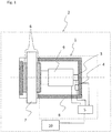
- Fig. 1 shows a schematic representation of a rail vehicle with a brake actuator according to the invention.
- a rail vehicle 2 is shown schematically, which has a brake actuator 1.
- the brake actuator 1 is assigned to a brake of the rail vehicle 2, which is represented here as a brake disk 7.
- a brake actuator 1 according to the invention it is not absolutely necessary for a brake actuator 1 according to the invention to be assigned to each brake.
- the brake actuator 1 has a sensor for detecting a braking force 3, by means of which a braking force generated in the brake actuator 1 is detected. Furthermore, the brake actuator 1 has a sensor for detecting vibrations 4, by means of whose vibrations generated by the braking force in the brake actuator 1 are detected.
- the sensor for detecting a braking force 3 and the sensor for detecting vibrations 4 can alternatively also be designed as a single sensor, which can then be arranged at the point at which the sensor for detecting a braking force 3 is shown. In this way, both the generated braking force and the vibrations generated by the braking force can then be recorded.
- the brake actuator 1 also has a control unit 5.
- the sensor for detecting a braking force 3 and the sensor for detecting vibrations 4 are connected to the control unit 5.
- the control unit 5 is configured to generate a relationship between a speed of the rail vehicle 2 and the generated braking force and a frequency of the vibrations generated by the braking force. When the rail vehicle is at a standstill, the control unit 6 optionally generates a standstill signal and outputs it.
- the control unit 5 is also configured to determine components of the frequency of the vibrations generated by the braking force by calculating correlation factors by calculating the standard deviation, a “fast Fourier transformation” (FFT) or a “discrete Fourier transformation” (DFT) .
- FFT fast Fourier transformation
- DFT discrete Fourier transformation
- the brake actuator 1 also has a pressing part 6, for example a brake lining. This pressing part 6 is pressed against the brake disk 7. On the opposite side with respect to the brake disk 7, a further pressing part 6 is shown in order to be able to clamp the brake disk 7 therebetween and to brake it.
- the brake has a brake caliper 8 which can be displaced with respect to the brake disc 7.
- a braking force generator 9 is also provided, which is shown here between one of the pressing parts 6 and the sensor for detecting a braking force 3.
- the braking force generator 9 is, for example, a compressed air cylinder.
- the brake actuator 1 is connected to a higher-level control system 10, which provides a speed signal from the rail vehicle 2.
- Normal operation is operation without a disturbance, such as an interruption in communication between the control unit 5 and the higher-level control system 10, so that the control unit 6 cannot be provided with a speed signal.
- the control unit 5 can detect the braking force generated in the brake actuator 1 during service braking.
- the control device 5 also detects the vibrations generated in the brake actuator 1 by the braking force.
- the vibrations generated by the braking force in the brake actuator 1 result from vibrations caused by the pressing of the pressing part 6 against the brake disk 7 or from an imbalance in the brake disk 7.
- the control unit 5 generates the relationship between the speed of the rail vehicle 2 with the generated braking force and the frequency of the braking force in the Brake actuator 1 generated vibrations. Components of the frequency are determined by calculating the correlation factors by calculating the standard deviation, the "fast Fourier transformation" (FFT) or the “discrete Fourier transformation” (DFT). From the calculations, coefficients are determined, which are then stored in the control unit 5 in a map.
- the map is continuously adapted in the event of service braking.
- the speed of the rail vehicle 2 is provided by the higher-level control system 10 and converted by the control unit 5 into a speed of rotation of the brake disc 7.
- the control unit 5 can also output a standstill signal while the rail vehicle 2 is at a standstill.
- the speed of the rail vehicle 2 can be determined from the detected braking force, the vibrations generated by the braking force and the coefficients stored in the map, and speed-dependent braking can be carried out despite the interruption in communication become.
Landscapes
- Engineering & Computer Science (AREA)
- Mechanical Engineering (AREA)
- Physics & Mathematics (AREA)
- Transportation (AREA)
- General Physics & Mathematics (AREA)
- General Engineering & Computer Science (AREA)
- Mathematical Physics (AREA)
- Theoretical Computer Science (AREA)
- Pure & Applied Mathematics (AREA)
- Data Mining & Analysis (AREA)
- Mathematical Optimization (AREA)
- Computational Mathematics (AREA)
- Mathematical Analysis (AREA)
- Algebra (AREA)
- Databases & Information Systems (AREA)
- Software Systems (AREA)
- Computing Systems (AREA)
- Regulating Braking Force (AREA)
- Braking Arrangements (AREA)
- Valves And Accessory Devices For Braking Systems (AREA)
Description
- Die vorliegende Erfindung bezieht sich auf einen Bremsaktuator für ein Schienenfahrzeug, insbesondere auf einen Bremsaktuator für ein Schienenfahrzeug, der autark funktionieren kann.
- Bei Betriebsbremsungen wird die erforderliche Bremskraft in aktuellen Schienenfahrzeugen kontinuierlich berechnet. Diese Berechnung erfolgt auf Basis einer gefahrenen Geschwindigkeit, eines Beladungszustands, einer Bremsanforderung und einer Verfügbarkeit von anderen Bremssystemen.
- Dokument
DE 10 2012 219984 A1 offenbart einen Bremsaktuator mit einem Sensor zum Ermitteln einer Anpressgröße des Bremsaktuators, einem Sensor zum Ermitteln einer Verzögerungsgröße und einem Raddrehzahlsensor, wobei eine Sollwertregelungseinrichtung die Anpressgröße so einstellt, dass ein Istwert der Verzögerungsgröße einem Sollwert entspricht. - Im Dokument
DE 10 2006 058566 A1 ist eine schwingungs- und geräuschminimierende Bremssteuerung, die Sensordaten, die Messwerte über die an einer Bremse auftretenden akustischen und fühlbaren Schwingungen liefen, auswertet, gezeigt. Dabei werden physikalische Messwerte, beispielsweise eine Zuspannkraft oder eine Temperatur, erfasst, sowie Schwingungen über Beschleunigungssensoren erfasst. -
WO 2013/034719 A2 offenbart eine Bremssteuereinrichtung zum Durchführen einer Zustandsanalyse eines Schienenfahrzeugs wobei ein Schwingungssensor und weitere Sensoren, wie beispielsweise ein Raddrehzahlsensor und ein Entgleisungssensor, vorgesehen sind. - Das Dokument
2007/0250246 A1 - Bei einer Notbremsung ist eine von einem Bremsaktuator lokal aufzubringende Bremskraft definiert, wobei diese Bremskraft ebenfalls von dem Beladungszustand und der Geschwindigkeit abhängig ist. Wenn jedoch ein Geschwindigkeitssignal gestört ist oder eine Kommunikation zwischen dem Bremsaktuator und einem übergeordneten Steuerungssystem, das ein Geschwindigkeitssignal ausgibt, gestört ist, kann die Geschwindigkeit des Schienenfahrzeugs nicht berücksichtigt werden. Aus diesem Grund werden Bremsen in Richtung "fail-safe" ausgelegt, so dass beim Bremsen eine maximal mögliche Geschwindigkeit angenommen wird, und die Bremsen werden dementsprechend dimensioniert.
- Eine solche Dimensionierung kann aber zu einer Überdimensionierung führen, so dass erhöhte Kosten entstehen. Andererseits kann es in einem Fehlerfall, nämlich dem Fehlen einer Geschwindigkeitsinformation, zu einer Verlängerung eines sicherheitsrelevanten Bremswegs kommen oder zu einer thermischen Überlastung der Bremsausrüstung führen.
- Ferner wird, da jedem Bremsaktuator zugeordnete Geschwindigkeitssensoren zu aufwändig sind, die Berechnung der Bremskraft und eine Ansteuerung der Bremsaktuator in aktuellen Bremssystemen auf Wagen- oder Drehgestellebene durchgeführt. Ein Ausfall einer Geschwindigkeitsinformation betrifft demensprechend auch immer eine solche Einheit.
- Der Erfindung liegt die Aufgabe zugrunde, Bremsaktuatoren bereitzustellen, die die obigen Nachteile eliminieren und sichere Bremsungen ermöglichen, ohne überdimensioniert zu sein.
- Die Aufgabe wird durch einen Bremsaktuator gemäß Anspruch 1 und ein Verfahren gemäß Anspruch 7 gelöst. Vorteilhafte Weiterentwicklungen sind Gegenstand der abhängigen Ansprüche.
- Durch einen Bremsaktuator gemäß den Aspekten des Anspruchs 1 kann ein Erzeugen eines Zusammenhangs zwischen einer Geschwindigkeit eines Schienenfahrzeugs mit einer durch einen Bremsaktuator erzeugten Bremskraft und einer Frequenz von durch die Bremskraft in dem Bremsaktuator erzeugten Schwingungen und somit eine Bestimmung der Geschwindigkeit aus den an dem Bremsaktuator verfügbaren Informationen lediglich über zusätzliche Sensoren für ein Erfassen einer erzeugten Bremskraft und ein Erfassen von durch die Bremskraft in den Bremsaktuatoren erzeugten Schwingungen erfolgen.
- Somit muss kein redundantes Kommunikationssystem vorgesehen werden, oder eine Überdimensionierung der Bremsen durchgeführt werden. Bei einer erkannten Notbremsung kann ferner ein lokaler Bremsaktuator eine geschwindigkeitsabhängige Notbremsung durchführen, ohne auf eine von Geschwindigkeitssensoren gemessene Geschwindigkeit oder eine Kommunikation mit einer Fahrzeugebene zurückgreifen zu müssen. Ferner kann ein sicherheitsrelevanter Bremsweg durch eine geringe Ausfallrate der Bremsaktuatoren verbessert werden.
- In einer vorteilhaften Weiterbildung weist der Bremsaktuator ein Anpressteil, also beispielsweise einen Bremsbelag, auf, das konfiguriert ist, gegen eine Bremsscheibe gedrückt zu werden. Durch das Drücken des Anpressteils an die Bremsscheibe können sowohl die Bremskraft als auch die durch das Drücken an die Bremsscheibe erzeugten Schwingungen einfach in jedem Bremsaktuator erfasst werden.
- In einer weiteren vorteilhaften Weiterentwicklung werden die Bremskraft und die durch die Bremskraft erzeugten Schwingungen durch einen einzigen Sensor erfasst. Ein solcher Sensor stützt beispielsweise einen Bremskrafterzeuger innerhalb eines Bremssattels des Bremsaktuators entgegen der Bremskraft ab, so dass gleichzeitig sowohl die Bremskraft als auch Schwingungen, die beispielsweise durch die Reibung eines Anpressteils an einer Bremsscheibe oder durch eine Unwucht der Bremsscheibe hervorgerufen werden, durch diesen Sensor erfasst werden können. Dadurch reduziert sich die Anzahl der Bauteile und somit werden die Kosten reduziert.
- Wenn der Bremskrafterzeuger in einem Normalbetrieb in einer vorteilhaften Weise mit einem übergeordneten Steuerungssystem, das konfiguriert ist, ein Geschwindigkeitssignal des Schienenfahrzeugs bereit zu stellen, verbunden ist, kann im Normalbetrieb auf dieses Geschwindigkeitssignal zurückgegriffen werden, um die geschwindigkeitsabhängige Bremskraft zu berechnen, und auch eine Zuordnung der Geschwindigkeit zu der erzeugten Bremskraft und durch die Bremskraft erzeugten Schwingungen kann erzeugt werden.
- Vorteilhafterweise ist die Steuerungseinheit konfiguriert, bei einem Stillstand des Schienenfahrzeugs ein Stillstandsignal auszugeben. Dieses von Geschwindigkeitssensoren unabhängige Stillstandsignal kann dann beispielsweise durch das übergeordnete Steuerungssystem zu Plausibilisieren eines sicherheitsrelevanten Stillstandsignals, beispielsweise für eine Freigabe zum Öffnen von Türen, verwendet werden. Da eine Vielzahl von Bremsaktuatoren im Schienenfahrzeug vorgesehen ist, ist eine Verfügbarkeit des Stillstandsignals hoch, wohingegen Stillstandsignale von Geschwindigkeitssensoren beispielsweise durch Einflüsse von elektrischen Feldern unzuverlässig sein können.
- In einer vorteilhaften Weiterentwicklung ist die Steuerungseinheit konfiguriert, Anteile der Frequenz über eine Berechnung von Korrelationsfaktoren über eine Berechnung der Standardabweichung, eine "schnelle Fourier-Transformation - FFT" oder eine "diskrete Fourier-Transformation - DFT" zu ermitteln. Dadurch können in einer einfachen Weise Koeffizienten berechnet werden, die für die Bestimmung des Zusammenhangs zwischen der Geschwindigkeit eines Schienenfahrzeugs mit der durch den Bremsaktuator erzeugten Bremskraft und der Frequenz der durch die Bremskraft in dem Bremsaktuator erzeugten Schwingungen verwendet werden können.
- Durch das Verfahren mit den Aspekten gemäß Anspruch 7 kann ein Erzeugen eines Zusammenhangs zwischen einer Geschwindigkeit eines Schienenfahrzeugs mit einer durch einen Bremsaktuator erzeugten Bremskraft und einer Frequenz von durch die Bremskraft in dem Bremsaktuator erzeugten Schwingungen und somit eine Bestimmung der Geschwindigkeit aus den an dem Bremsaktuator verfügbaren Informationen lediglich über zusätzliche Sensoren für ein Erfassen einer erzeugten Bremskraft und ein Erfassen von durch die Bremskraft in den Bremsaktuatoren erzeugten Schwingungen erfolgen. Somit muss kein redundantes Kommunikationssystem vorzusehen sein, oder keine Überdimensionierung der Bremsen durchgeführt werden.
- In einer vorteilhaften Weiterbildung des Verfahrens, in der das Geschwindigkeitssignal über das übergeordnete Steuerungssystem bereitgestellt wird, kann im Normalbetrieb auf dieses Geschwindigkeitssignal zurückgegriffen werden, um die geschwindigkeitsabhängige Bremskraft zu berechnen, und auch eine Zuordnung der Geschwindigkeit zu der erzeugten Bremskraft und der durch die Bremskraft erzeugten Schwingungen kann erzeugt werden.
- Das Verfahren kann, durch eine Umrechnung der Geschwindigkeit des Schienenfahrzeugs, in eine Rotationsgeschwindigkeit der Bremsscheibe berechnete Frequenzen in einer vorteilhaften Weise einer Drehzahl der Bremsscheibe zuordnen.
- Wenn die Schritte zum Bestimmen der Geschwindigkeit des Schienenfahrzeugs mit dem Bremsaktuator während Betriebsbremsungen durchgeführt werden, ist es möglich, die Zuordnung ohne beispielsweise zusätzliche Probebremsungen durchzuführen.
- Bei einem vorteilhaften Ausgeben des Stillstandsignals bei dem Stillstand des Schienenfahrzeugs kann dieses von Geschwindigkeitssensoren unabhängige Stillstandsignal dann beispielsweise durch das übergeordnete Steuerungssystem zu Plausibilisieren eines sicherheitsrelevanten Stillstandsignals, beispielsweise für eine Freigabe zum Öffnen von Türen, verwendet werden.
- Die Anteile der Frequenz können vorteilhafterweise über eine Berechnung von Korrelationsfaktoren über die Berechnung der Standardabweichung, die "schnelle Fourier-Transformation - FFT" oder die "diskrete Fourier-Transformation - DFT" ermittelt werden. Dadurch können in einer einfachen Weise Koeffizienten berechnet werden, die für die Bestimmung des Zusammenhangs zwischen der Geschwindigkeit eines Schienenfahrzeugs mit der durch einen Bremsaktuator erzeugten Bremskraft und der Frequenz der durch die Bremskraft in dem Bremsaktuator erzeugten Schwingungen verwendet werden können.
- Vorzugsweise werden die Koeffizienten in einem Kennfeld gespeichert, um, in einem Fall eines Fehlens einer Geschwindigkeitsinformation des übergeordneten Steuerungssystems, für jeden Bremsaktuator geeignete geschwindigkeitsabhängige Bremsparameter zu verwenden.
- Wenn das Kennfeld vorteilhafterweise kontinuierlich, nämliche beispielsweise bei jeder Betriebsbremsung, angepasst wird, können Änderungen des Bremssystems durch Alterung und Verschleiß einfach berücksichtigt werden.
- Bei einer Unterbrechung der Kommunikation kann die Steuerungseinheit die Geschwindigkeit des Schienenfahrzeugs aus der erfassten erzeugten Bremskraft, der durch die Bremskraft in dem Bremsaktuator erzeugten Schwingungen und den in dem Kennfeld gespeicherten Koeffizienten ermitteln und somit eine geeignete aufzubringende Bremskraft bestimmen, um eine geschwindigkeitsabhängige Bremsung durchzuführen.
- Die Erfindung wird nun anhand eines Ausführungsbeispiels unter Bezugnahme auf die beigefügte Zeichnung erläutert.
-
Fig. 1 zeigt eine schematische Darstellung eines Schienenfahrzeugs mit einem erfindungsgemäßen Bremsaktuator. - In
Fig. 1 ist schematisch ein Schienenfahrzeug 2 dargestellt, das einen Bremsaktuator 1 aufweist. Der Bremsaktuator 1 ist jeweils einer Bremse des Schienenfahrzeugs 2, die hier als eine Bremsscheibe 7 repräsentiert wird, zugeordnet. Es ist aber alternativ nicht zwingend erforderlich, dass jeder Bremse ein erfindungsgemäßer Bremsaktuator 1 zugeordnet ist. - Der Bremsaktuator 1 weist einen Sensor zum Erfassen einer Bremskraft 3, mittels dessen eine in dem Bremsaktuator 1 erzeugte Bremskraft erfasst wird, auf. Ferner weist der Bremsaktuator 1 einen Sensor zum Erfassen von Schwingungen 4 auf, mittels dessen durch die Bremskraft in dem Bremsaktuator 1 erzeugte Schwingungen erfasst werden. Der Sensor zum Erfassen einer Bremskraft 3 und der Sensor zum Erfassen von Schwingungen 4 können alternativ auch als ein einziger Sensor ausgebildet sein, wobei dieser dann an der Stelle angeordnet sein kann, an dem der Sensor zum Erfassen einer Bremskraft 3 dargestellt ist. Damit können dann sowohl die erzeugte Bremskraft als auch die durch die Bremskraft erzeugten Schwingungen erfasst werden.
- Ferner weist der Bremsaktuator 1 eine Steuerungseinheit 5 auf. Der Sensor zum Erfassen einer Bremskraft 3 und der Sensor zum Erfassen von Schwingungen 4 sind mit der Steuerungseinheit 5 verbunden. Die Steuerungseinheit 5 ist konfiguriert, einen Zusammenhang einer Geschwindigkeit des Schienenfahrzeugs 2 mit der erzeugten Bremskraft und einer Frequenz der durch die Bremskraft erzeugten Schwingungen zu erzeugen. Bei einem Stillstand des Schienenfahrzeugs erzeugt die Steuerungseinheit 6 optional ein Stillstandsignal und gibt es aus. Ferner ist die Steuerungseinheit 5 konfiguriert, Anteile der Frequenz der durch die Bremskraft erzeugten Schwingungen über eine Berechnung von Korrelationsfaktoren über eine Berechnung der Standardabweichung, eine "schnelle Fourier-Transformation" (FFT) oder eine "diskrete Fourier-Transformation" (DFT) zu ermitteln.
- Der Bremsaktuator 1 weist außerdem ein Anpressteil 6, beispielsweise einen Bremsbelag, auf. Dieses Anpressteil 6 wird gegen die Bremsscheibe 7 gedrückt. Auf der bezüglich der Bremsscheibe 7 gegenüberliegenden Seite ist ein weiteres Anpressteil 6 dargestellt, um die Bremsscheibe 7 dazwischen einklemmen und bremsen zu können. Dazu weist die Bremse einen Bremssattel 8 auf, der gegenüber der Bremsscheibe 7 verschiebbar sein kann.
- In dem Bremssattel 8 ist ferner ein Bremskrafterzeuger 9 vorgesehen, der hier zwischen einem der Anpressteile 6 und dem Sensor zum Erfassen einer Bremskraft 3 dargestellt ist. Der Bremskrafterzeuger 9 ist beispielsweise ein Druckluftzylinder.
- Der Bremsaktuator 1 ist im Normalbetrieb mit einen übergeordneten Steuerungssystem 10, das ein Geschwindigkeitssignal des Schienenfahrzeugs 2 zur Verfügung stellt, verbunden. Der Normalbetrieb ist ein Betrieb ohne Störung, wie beispielsweise eine Unterbrechung einer Kommunikation zwischen der Steuerungseinheit 5 und dem übergeordneten Steuerungssystem 10, so dass der Steuerungseinheit 6 kein Geschwindigkeitssignal zur Verfügung gestellt werden kann.
- Im Betrieb kann die Steuerungseinheit 5 während Betriebsbremsungen die in dem Bremsaktuator 1 erzeugte Bremskraft erfassen. Ferner erfasst die Steuerungseinrichtung 5 die durch die Bremskraft in dem Bremsaktuator 1 erzeugten Schwingungen. Die durch die Bremskraft in dem Bremsaktuator 1 erzeugten Schwingungen rühren von Schwingungen durch das Drücken des Anpressteils 6 an die Bremsscheibe 7 oder durch eine Unwucht der Bremsscheibe 7 her. Dann erzeugt die Steuerungseinheit 5 den Zusammenhang der Geschwindigkeit des Schienenfahrzeugs 2 mit der erzeugten Bremskraft und der Frequenz der durch die Bremskraft in dem Bremsaktuator 1 erzeugten Schwingungen. Anteile der Frequenz werden über die Berechnung der Korrelationsfaktoren über die Berechnung der Standardabweichung, die "schnelle Fourier-Transformation" (FFT) oder die "diskrete Fourier-Transformation" (DFT) ermittelt. Aus den Berechnungen werden Koeffizienten bestimmt, die dann in der Steuerungseinheit 5 in einem Kennfeld gespeichert werden. Das Kennfeld wird bei Betriebsbremsungen kontinuierlich angepasst.
- Die Geschwindigkeit des Schienenfahrzeugs 2 wird von dem übergeordneten Steuerungssystem 10 bereitgestellt und von der Steuerungseinheit 5 in eine Rotationsgeschwindigkeit der Bremsscheibe 7 umgerechnet.
- Die Steuerungseinheit 5 kann ferner während eines Stillstands des Schienenfahrzeugs 2 ein Stillstandsignal ausgeben.
- Bei der Unterbrechung der Kommunikation zwischen der Steuerungseinheit 5 und dem übergeordneten Steuerungssystem 10 kann die Geschwindigkeit des Schienenfahrzeugs 2 aus der erfassten Bremskraft, der durch die Bremskraft erzeugten Schwingungen und den im Kennfeld gespeicherten Koeffizienten ermittelt werden und trotz der Unterbrechung der Kommunikation kann eine geschwindigkeitsabhängige Bremsung durchgeführt werden.
-
- 1
- Bremsaktuator
- 2
- Schienenfahrzeug
- 3
- Sensor zum Erfassen einer Bremskraft
- 4
- Sensor zum Erfassen von Schwingungen
- 5
- Steuerungseinheit
- 6
- Anpressteil
- 7
- Bremsscheibe
- 8
- Bremssattel
- 9
- Bremskrafterzeuger
- 10
- übergeordnetes Steuerungssystem
Claims (15)
- Bremsaktuator (1) für ein Schienenfahrzeug (2) mit
einem Sensor (3) zum Erfassen einer in dem Bremsaktuator (1) erzeugten Bremskraft,
einem Sensor (4) zum Erfassen von durch die Bremskraft in dem Bremsaktuator (1) erzeugten Schwingungen, und
einer Steuerungseinheit (5), dadurch gekennzeichnet, dass
die Steuerungseinheit (5) konfiguriert ist, einen Zusammenhang einer Geschwindigkeit des Schienenfahrzeugs (2) mit der erzeugten Bremskraft und einer Frequenz der durch die Bremskraft erzeugten Schwingungen zu erzeugen. - Bremsaktuator (1) gemäß Anspruch 1, wobei
der Bremsaktuator (1) ein Anpressteil (6) aufweist, das dazu konfiguriert ist, an eine Bremsscheibe (7) gedrückt zu werden. - Bremsaktuator (1) gemäß einem der Ansprüche 1 oder 2, wobei
der Sensor (3) zum Erfassen der in dem Bremsaktuator (1) erzeugten Bremskraft und der Sensor (4) zum Erfassen von durch die Bremskraft in dem Bremsaktuator (1) erzeugten Schwingungen als ein einziger Sensor ausgebildet sind. - Bremsaktuator (1) gemäß einem der vorangehenden Ansprüche, wobei
die Steuerungseinheit (5) in einem Normalbetrieb mit einem übergeordneten Steuerungssystem (10) verbunden ist, das konfiguriert ist, ein Geschwindigkeitssignal des Schienenfahrzeugs (2) bereitzustellen. - Bremsaktuator (1) gemäß einem der vorangehenden Ansprüche, wobei
die Steuerungseinheit (5) konfiguriert ist, bei einem Stillstand des Schienenfahrzeugs (2), ein Stillstandsignal zu erzeugen. - Bremsaktuator (1) gemäß einem der vorangehenden Ansprüche, wobei
die Steuerungseinheit (5) konfiguriert ist, Anteile der Frequenz über eine Berechnung von Korrelationsfaktoren über eine Berechnung der Standardabweichung, eine "schnellen Fourier-Transformation - FFT" oder eine "diskrete Fourier-Transformation - DFT" zu ermitteln. - Verfahren zum Bestimmen einer Geschwindigkeit eines Schienenfahrzeugs (2) mit einem Bremsaktuator (1) gemäß einem der Ansprüche 1 bis 6 mit den Schritten
Erfassen einer in dem Bremsaktuator (1) erzeugten Bremskraft;
Erfassen von in dem Bremsaktuator (1) durch die Bremskraft erzeugten Schwingungen;
Erzeugen eines Zusammenhangs der Geschwindigkeit des Schienenfahrzeugs (2) mit der erzeugten Bremskraft und einer Frequenz der durch die Bremskraft erzeugten Schwingungen. - Verfahren gemäß Anspruch 7, wobei die Geschwindigkeit von einem übergeordneten Steuerungssystem (10) bereitgestellt wird.
- Verfahren gemäß Anspruch 7 oder 8, wobei die Geschwindigkeit des Schienenfahrzeugs (2) in eine Rotationsgeschwindigkeit einer Bremsscheibe (7) umgerechnet wird.
- Verfahren gemäß einem der Ansprüche 7 bis 9, wobei
die Schritte während Betriebsbremsungen durchgeführt werden. - Verfahren gemäß einem der Ansprüche 7 bis 10, wobei
bei einem Stillstand des Schienenfahrzeugs (2) ein Stillstandsignal ausgegeben wird. - Verfahren gemäß einem der Ansprüche 7 bis 11, wobei
Anteile der Frequenz über eine Berechnung der Korrelationsfaktoren über die Berechnung der Standardabweichung, die "schnelle Fourier-Transformation - FFT" oder die "diskrete Fourier-Transformation - DFT" ermittelt werden. - Verfahren gemäß Anspruch 12, mit den Schritten
Bestimmen von Koeffizienten aus den Korrelationsfaktoren;
Speichern der Koeffizienten in einem Kennfeld. - Verfahren gemäß Anspruch 13, wobei
das Kennfeld kontinuierlich angepasst wird. - Verfahren gemäß einem der Ansprüche 13 oder 14, wobei
die Steuerungseinheit (5), bei einer Unterbrechung einer Kommunikation, die Geschwindigkeit aus der erfassten erzeugten Bremskraft, der durch die Bremskraft erzeugten Schwingungen und den in dem Kennfeld gespeicherten Koeffizienten ermittelt.
Applications Claiming Priority (2)
| Application Number | Priority Date | Filing Date | Title |
|---|---|---|---|
| DE102017215293.1A DE102017215293A1 (de) | 2017-08-31 | 2017-08-31 | Bremsaktuator für ein Schienenfahrzeug |
| PCT/EP2018/072627 WO2019042835A1 (de) | 2017-08-31 | 2018-08-22 | Bremsaktuator für ein schienenfahrzeug |
Publications (2)
| Publication Number | Publication Date |
|---|---|
| EP3676140A1 EP3676140A1 (de) | 2020-07-08 |
| EP3676140B1 true EP3676140B1 (de) | 2021-07-07 |
Family
ID=63490416
Family Applications (1)
| Application Number | Title | Priority Date | Filing Date |
|---|---|---|---|
| EP18765038.7A Active EP3676140B1 (de) | 2017-08-31 | 2018-08-22 | Bremsaktuator für ein schienenfahrzeug |
Country Status (5)
| Country | Link |
|---|---|
| US (1) | US20200377071A1 (de) |
| EP (1) | EP3676140B1 (de) |
| CN (1) | CN111032460A (de) |
| DE (1) | DE102017215293A1 (de) |
| WO (1) | WO2019042835A1 (de) |
Families Citing this family (1)
| Publication number | Priority date | Publication date | Assignee | Title |
|---|---|---|---|---|
| IT202200027363A1 (it) * | 2022-12-30 | 2024-06-30 | Itt Italia Srl | Metodo e dispositivo per stimare la velocità di un veicolo |
Family Cites Families (11)
| Publication number | Priority date | Publication date | Assignee | Title |
|---|---|---|---|---|
| US5511867A (en) * | 1995-05-05 | 1996-04-30 | Kelsey-Hayes Company | Method and system for drivetrain oscillation detection and control for anti-lock brake systems |
| CN2241329Y (zh) * | 1995-06-30 | 1996-11-27 | 清华大学 | 低频振动速度传感器 |
| JP4507772B2 (ja) * | 2004-09-08 | 2010-07-21 | トヨタ自動車株式会社 | 液圧制御装置 |
| US7366590B2 (en) * | 2006-03-23 | 2008-04-29 | Mitchell Gabriel Mircea Balasu | Impending failure and failure annunciation systems for actuators and drive train components |
| DE102006058566A1 (de) * | 2006-12-12 | 2008-06-19 | Siemens Ag | Schwingungs- und geräuschminimierende Bremssteuerung |
| DE102011113084A1 (de) * | 2011-09-09 | 2013-03-14 | Knorr-Bremse Systeme für Schienenfahrzeuge GmbH | Bremssteuereinrichtung für eine Bremsanlage eines Schienenfahrzeugs, Bremsanlage, Schienenfahrzeug sowie Verfahren zum Durchführen einer Zustandsanalyse eines Schienenfahrzeugs |
| CN202743276U (zh) * | 2012-05-07 | 2013-02-20 | 宝鸡南车时代工程机械有限公司 | 带探伤装置的铁路轨道车转向架 |
| DE102012219984A1 (de) * | 2012-10-31 | 2014-04-30 | Siemens Aktiengesellschaft | Bremsaktor für ein Bremssystem eines Fahrzeugs, insbesondere eines Schienenfahrzeugs |
| DE102015110053A1 (de) * | 2015-06-23 | 2016-12-29 | Knorr-Bremse Systeme für Schienenfahrzeuge GmbH | Bremssystem für ein Schienenfahrzeug |
| US20220191721A1 (en) * | 2019-06-26 | 2022-06-16 | Lg Electronics Inc. | Method and apparatus for performing discontinuous reception procedure in wireless communication system |
| US11808859B2 (en) * | 2020-12-10 | 2023-11-07 | GM Global Technology Operations LLC | System and method of depth imaging based on rolling shutter cmos image sensor and down conversion techniques |
-
2017
- 2017-08-31 DE DE102017215293.1A patent/DE102017215293A1/de not_active Ceased
-
2018
- 2018-08-22 WO PCT/EP2018/072627 patent/WO2019042835A1/de not_active Ceased
- 2018-08-22 US US16/643,352 patent/US20200377071A1/en not_active Abandoned
- 2018-08-22 EP EP18765038.7A patent/EP3676140B1/de active Active
- 2018-08-22 CN CN201880056147.9A patent/CN111032460A/zh active Pending
Non-Patent Citations (1)
| Title |
|---|
| None * |
Also Published As
| Publication number | Publication date |
|---|---|
| CN111032460A (zh) | 2020-04-17 |
| US20200377071A1 (en) | 2020-12-03 |
| DE102017215293A1 (de) | 2019-02-28 |
| EP3676140A1 (de) | 2020-07-08 |
| WO2019042835A1 (de) | 2019-03-07 |
Similar Documents
| Publication | Publication Date | Title |
|---|---|---|
| EP2753512B1 (de) | Bremssteuereinrichtung für eine bremsanlage, bremsanlage, schienenfahrzeug sowie verfahren zum betreiben einer bremsanlage | |
| DE102007035326A1 (de) | Sensorkonzept für eine elektrisch betätigte Bremse | |
| EP3353022B1 (de) | Validierungs- und zertifizierungsverfahren für ein schienenfahrzeug | |
| DE102016208613A1 (de) | Bremsvorrichtung für ein Kraftfahrzeug und Verfahren zur Detektion einer Beschädigung der Bremsvorrichtung | |
| EP3036137B1 (de) | Bremsaktor für ein bremssystem eines fahrzeugs sowie verfahren zum abbremsen eines fahrzeugs | |
| DE112020000915T5 (de) | Motorsteuervorrichtung und Elektrobremsvorrichtung die sie verwendet, und Motorsteuerverfahren und Elektrobremssteuerverfahren, das es verwendet | |
| DE102006015034B4 (de) | Verfahren und Recheneinheit zur Bestimmung eines Leistungsparameters einer Bremse | |
| DE102015212300A1 (de) | Verfahren und Vorrichtung zum Betreiben eines Kraftfahrzeugs, Kraftfahrzeug | |
| EP4188770B1 (de) | Kupplungsanordnung mit überwachungssystem sowie verfahren zum überwachen einer kupplungsanordnung | |
| DE10233845B4 (de) | Diagnose- und Überwachungsvorrichtung einer Bremszuspanneinrichtung eines Fahrzeugs | |
| DE102008049224A1 (de) | Verfahren und Vorrichtung zum Überprüfen mindestens eines Laufwerks eines auf einem Gleis fahrbaren Schienenfahrzeugs auf einen Defekt | |
| EP3676140B1 (de) | Bremsaktuator für ein schienenfahrzeug | |
| EP2753517B1 (de) | Verfahren zum überwachen eines rades eines schienenfahrzeuges | |
| WO2005021347A1 (de) | Notbremseinrichtung und bremssystem für ein schienenfahrzeug sowie verfahren zum sicherstellen einer notbremsfunktion bei schienenfahrzeugen | |
| EP3774470A1 (de) | Überwachung einer elektrodynamischen bremse in einem schienenfahrzeug | |
| DE102018203181B4 (de) | Verfahren zur Überprüfung des korrekten Verbaus einer elektronischen Parkbremse eines Kraftfahrzeugs und Prüfanordnung | |
| EP3619081A1 (de) | Schienenfahrzeugbremssystem und verfahren zum betreiben eines schienenfahrzeugbremssystems | |
| DE102009016986A1 (de) | Verfahren und Einrichtung zur Bremskraftsteuerung | |
| WO2001084105A1 (de) | Verfahren und vorrichtung zum überwachen von fahreigenschaften eines schienenfahrzeuges | |
| DE102017106119A1 (de) | Bremsvorrichtung für Schienenfahrzeuge und Verfahren zum Bremsen von Schienenfahrzeugen | |
| DE102012022801A1 (de) | Verfahren zur Lenkungsüberwachung und Lenksystem | |
| EP1041376A2 (de) | Vibrationsakustisches Diagnosesystem zur Erfassung von Schäden an Kraftfahrzeugbauteilen | |
| DE102020205848A1 (de) | Verfahren und Vorrichtung zum Betreiben eines Feststellbremssystems | |
| DE102010038307A1 (de) | Verfahren und Vorrichtung zur Regelung und/oder Überwachung einer elektrisch betätigbaren Bremse sowie elektronisches Bremssystem | |
| DE102016225529A1 (de) | Scheibenbremse für ein Fahrzeug und Betriebsverfahren für eine Scheibenbremse |
Legal Events
| Date | Code | Title | Description |
|---|---|---|---|
| STAA | Information on the status of an ep patent application or granted ep patent |
Free format text: STATUS: UNKNOWN |
|
| STAA | Information on the status of an ep patent application or granted ep patent |
Free format text: STATUS: THE INTERNATIONAL PUBLICATION HAS BEEN MADE |
|
| PUAI | Public reference made under article 153(3) epc to a published international application that has entered the european phase |
Free format text: ORIGINAL CODE: 0009012 |
|
| STAA | Information on the status of an ep patent application or granted ep patent |
Free format text: STATUS: REQUEST FOR EXAMINATION WAS MADE |
|
| 17P | Request for examination filed |
Effective date: 20200331 |
|
| AK | Designated contracting states |
Kind code of ref document: A1 Designated state(s): AL AT BE BG CH CY CZ DE DK EE ES FI FR GB GR HR HU IE IS IT LI LT LU LV MC MK MT NL NO PL PT RO RS SE SI SK SM TR |
|
| AX | Request for extension of the european patent |
Extension state: BA ME |
|
| DAV | Request for validation of the european patent (deleted) | ||
| DAX | Request for extension of the european patent (deleted) | ||
| GRAP | Despatch of communication of intention to grant a patent |
Free format text: ORIGINAL CODE: EPIDOSNIGR1 |
|
| STAA | Information on the status of an ep patent application or granted ep patent |
Free format text: STATUS: GRANT OF PATENT IS INTENDED |
|
| INTG | Intention to grant announced |
Effective date: 20210128 |
|
| GRAS | Grant fee paid |
Free format text: ORIGINAL CODE: EPIDOSNIGR3 |
|
| GRAA | (expected) grant |
Free format text: ORIGINAL CODE: 0009210 |
|
| STAA | Information on the status of an ep patent application or granted ep patent |
Free format text: STATUS: THE PATENT HAS BEEN GRANTED |
|
| AK | Designated contracting states |
Kind code of ref document: B1 Designated state(s): AL AT BE BG CH CY CZ DE DK EE ES FI FR GB GR HR HU IE IS IT LI LT LU LV MC MK MT NL NO PL PT RO RS SE SI SK SM TR |
|
| REG | Reference to a national code |
Ref country code: GB Ref legal event code: FG4D Free format text: NOT ENGLISH |
|
| REG | Reference to a national code |
Ref country code: AT Ref legal event code: REF Ref document number: 1408290 Country of ref document: AT Kind code of ref document: T Effective date: 20210715 |
|
| REG | Reference to a national code |
Ref country code: DE Ref legal event code: R096 Ref document number: 502018006073 Country of ref document: DE |
|
| REG | Reference to a national code |
Ref country code: IE Ref legal event code: FG4D Free format text: LANGUAGE OF EP DOCUMENT: GERMAN |
|
| REG | Reference to a national code |
Ref country code: LT Ref legal event code: MG9D |
|
| REG | Reference to a national code |
Ref country code: NL Ref legal event code: MP Effective date: 20210707 |
|
| PG25 | Lapsed in a contracting state [announced via postgrant information from national office to epo] |
Ref country code: HR Free format text: LAPSE BECAUSE OF FAILURE TO SUBMIT A TRANSLATION OF THE DESCRIPTION OR TO PAY THE FEE WITHIN THE PRESCRIBED TIME-LIMIT Effective date: 20210707 Ref country code: ES Free format text: LAPSE BECAUSE OF FAILURE TO SUBMIT A TRANSLATION OF THE DESCRIPTION OR TO PAY THE FEE WITHIN THE PRESCRIBED TIME-LIMIT Effective date: 20210707 Ref country code: FI Free format text: LAPSE BECAUSE OF FAILURE TO SUBMIT A TRANSLATION OF THE DESCRIPTION OR TO PAY THE FEE WITHIN THE PRESCRIBED TIME-LIMIT Effective date: 20210707 Ref country code: RS Free format text: LAPSE BECAUSE OF FAILURE TO SUBMIT A TRANSLATION OF THE DESCRIPTION OR TO PAY THE FEE WITHIN THE PRESCRIBED TIME-LIMIT Effective date: 20210707 Ref country code: SE Free format text: LAPSE BECAUSE OF FAILURE TO SUBMIT A TRANSLATION OF THE DESCRIPTION OR TO PAY THE FEE WITHIN THE PRESCRIBED TIME-LIMIT Effective date: 20210707 Ref country code: LT Free format text: LAPSE BECAUSE OF FAILURE TO SUBMIT A TRANSLATION OF THE DESCRIPTION OR TO PAY THE FEE WITHIN THE PRESCRIBED TIME-LIMIT Effective date: 20210707 Ref country code: BG Free format text: LAPSE BECAUSE OF FAILURE TO SUBMIT A TRANSLATION OF THE DESCRIPTION OR TO PAY THE FEE WITHIN THE PRESCRIBED TIME-LIMIT Effective date: 20211007 Ref country code: NO Free format text: LAPSE BECAUSE OF FAILURE TO SUBMIT A TRANSLATION OF THE DESCRIPTION OR TO PAY THE FEE WITHIN THE PRESCRIBED TIME-LIMIT Effective date: 20211007 Ref country code: PT Free format text: LAPSE BECAUSE OF FAILURE TO SUBMIT A TRANSLATION OF THE DESCRIPTION OR TO PAY THE FEE WITHIN THE PRESCRIBED TIME-LIMIT Effective date: 20211108 Ref country code: NL Free format text: LAPSE BECAUSE OF FAILURE TO SUBMIT A TRANSLATION OF THE DESCRIPTION OR TO PAY THE FEE WITHIN THE PRESCRIBED TIME-LIMIT Effective date: 20210707 |
|
| PG25 | Lapsed in a contracting state [announced via postgrant information from national office to epo] |
Ref country code: PL Free format text: LAPSE BECAUSE OF FAILURE TO SUBMIT A TRANSLATION OF THE DESCRIPTION OR TO PAY THE FEE WITHIN THE PRESCRIBED TIME-LIMIT Effective date: 20210707 Ref country code: LV Free format text: LAPSE BECAUSE OF FAILURE TO SUBMIT A TRANSLATION OF THE DESCRIPTION OR TO PAY THE FEE WITHIN THE PRESCRIBED TIME-LIMIT Effective date: 20210707 Ref country code: GR Free format text: LAPSE BECAUSE OF FAILURE TO SUBMIT A TRANSLATION OF THE DESCRIPTION OR TO PAY THE FEE WITHIN THE PRESCRIBED TIME-LIMIT Effective date: 20211008 |
|
| REG | Reference to a national code |
Ref country code: CH Ref legal event code: PL |
|
| REG | Reference to a national code |
Ref country code: DE Ref legal event code: R097 Ref document number: 502018006073 Country of ref document: DE |
|
| REG | Reference to a national code |
Ref country code: BE Ref legal event code: MM Effective date: 20210831 |
|
| PG25 | Lapsed in a contracting state [announced via postgrant information from national office to epo] |
Ref country code: LI Free format text: LAPSE BECAUSE OF NON-PAYMENT OF DUE FEES Effective date: 20210831 Ref country code: DK Free format text: LAPSE BECAUSE OF FAILURE TO SUBMIT A TRANSLATION OF THE DESCRIPTION OR TO PAY THE FEE WITHIN THE PRESCRIBED TIME-LIMIT Effective date: 20210707 Ref country code: CH Free format text: LAPSE BECAUSE OF NON-PAYMENT OF DUE FEES Effective date: 20210831 |
|
| PLBE | No opposition filed within time limit |
Free format text: ORIGINAL CODE: 0009261 |
|
| STAA | Information on the status of an ep patent application or granted ep patent |
Free format text: STATUS: NO OPPOSITION FILED WITHIN TIME LIMIT |
|
| PG25 | Lapsed in a contracting state [announced via postgrant information from national office to epo] |
Ref country code: SM Free format text: LAPSE BECAUSE OF FAILURE TO SUBMIT A TRANSLATION OF THE DESCRIPTION OR TO PAY THE FEE WITHIN THE PRESCRIBED TIME-LIMIT Effective date: 20210707 Ref country code: SK Free format text: LAPSE BECAUSE OF FAILURE TO SUBMIT A TRANSLATION OF THE DESCRIPTION OR TO PAY THE FEE WITHIN THE PRESCRIBED TIME-LIMIT Effective date: 20210707 Ref country code: RO Free format text: LAPSE BECAUSE OF FAILURE TO SUBMIT A TRANSLATION OF THE DESCRIPTION OR TO PAY THE FEE WITHIN THE PRESCRIBED TIME-LIMIT Effective date: 20210707 Ref country code: MC Free format text: LAPSE BECAUSE OF FAILURE TO SUBMIT A TRANSLATION OF THE DESCRIPTION OR TO PAY THE FEE WITHIN THE PRESCRIBED TIME-LIMIT Effective date: 20210707 Ref country code: LU Free format text: LAPSE BECAUSE OF NON-PAYMENT OF DUE FEES Effective date: 20210822 Ref country code: EE Free format text: LAPSE BECAUSE OF FAILURE TO SUBMIT A TRANSLATION OF THE DESCRIPTION OR TO PAY THE FEE WITHIN THE PRESCRIBED TIME-LIMIT Effective date: 20210707 Ref country code: CZ Free format text: LAPSE BECAUSE OF FAILURE TO SUBMIT A TRANSLATION OF THE DESCRIPTION OR TO PAY THE FEE WITHIN THE PRESCRIBED TIME-LIMIT Effective date: 20210707 Ref country code: AL Free format text: LAPSE BECAUSE OF FAILURE TO SUBMIT A TRANSLATION OF THE DESCRIPTION OR TO PAY THE FEE WITHIN THE PRESCRIBED TIME-LIMIT Effective date: 20210707 |
|
| 26N | No opposition filed |
Effective date: 20220408 |
|
| PG25 | Lapsed in a contracting state [announced via postgrant information from national office to epo] |
Ref country code: IT Free format text: LAPSE BECAUSE OF FAILURE TO SUBMIT A TRANSLATION OF THE DESCRIPTION OR TO PAY THE FEE WITHIN THE PRESCRIBED TIME-LIMIT Effective date: 20210707 Ref country code: IE Free format text: LAPSE BECAUSE OF NON-PAYMENT OF DUE FEES Effective date: 20210822 Ref country code: FR Free format text: LAPSE BECAUSE OF NON-PAYMENT OF DUE FEES Effective date: 20210907 Ref country code: BE Free format text: LAPSE BECAUSE OF NON-PAYMENT OF DUE FEES Effective date: 20210831 |
|
| PGFP | Annual fee paid to national office [announced via postgrant information from national office to epo] |
Ref country code: DE Payment date: 20220822 Year of fee payment: 5 |
|
| GBPC | Gb: european patent ceased through non-payment of renewal fee |
Effective date: 20220822 |
|
| P01 | Opt-out of the competence of the unified patent court (upc) registered |
Effective date: 20230508 |
|
| PG25 | Lapsed in a contracting state [announced via postgrant information from national office to epo] |
Ref country code: CY Free format text: LAPSE BECAUSE OF FAILURE TO SUBMIT A TRANSLATION OF THE DESCRIPTION OR TO PAY THE FEE WITHIN THE PRESCRIBED TIME-LIMIT Effective date: 20210707 |
|
| PG25 | Lapsed in a contracting state [announced via postgrant information from national office to epo] |
Ref country code: HU Free format text: LAPSE BECAUSE OF FAILURE TO SUBMIT A TRANSLATION OF THE DESCRIPTION OR TO PAY THE FEE WITHIN THE PRESCRIBED TIME-LIMIT; INVALID AB INITIO Effective date: 20180822 |
|
| PG25 | Lapsed in a contracting state [announced via postgrant information from national office to epo] |
Ref country code: GB Free format text: LAPSE BECAUSE OF NON-PAYMENT OF DUE FEES Effective date: 20220822 |
|
| REG | Reference to a national code |
Ref country code: DE Ref legal event code: R119 Ref document number: 502018006073 Country of ref document: DE |
|
| PG25 | Lapsed in a contracting state [announced via postgrant information from national office to epo] |
Ref country code: MK Free format text: LAPSE BECAUSE OF FAILURE TO SUBMIT A TRANSLATION OF THE DESCRIPTION OR TO PAY THE FEE WITHIN THE PRESCRIBED TIME-LIMIT Effective date: 20210707 |
|
| PG25 | Lapsed in a contracting state [announced via postgrant information from national office to epo] |
Ref country code: TR Free format text: LAPSE BECAUSE OF FAILURE TO SUBMIT A TRANSLATION OF THE DESCRIPTION OR TO PAY THE FEE WITHIN THE PRESCRIBED TIME-LIMIT Effective date: 20210707 |
|
| PG25 | Lapsed in a contracting state [announced via postgrant information from national office to epo] |
Ref country code: DE Free format text: LAPSE BECAUSE OF NON-PAYMENT OF DUE FEES Effective date: 20240301 |
|
| PG25 | Lapsed in a contracting state [announced via postgrant information from national office to epo] |
Ref country code: MT Free format text: LAPSE BECAUSE OF FAILURE TO SUBMIT A TRANSLATION OF THE DESCRIPTION OR TO PAY THE FEE WITHIN THE PRESCRIBED TIME-LIMIT Effective date: 20210707 |
|
| REG | Reference to a national code |
Ref country code: AT Ref legal event code: MM01 Ref document number: 1408290 Country of ref document: AT Kind code of ref document: T Effective date: 20230822 |
|
| PG25 | Lapsed in a contracting state [announced via postgrant information from national office to epo] |
Ref country code: AT Free format text: LAPSE BECAUSE OF NON-PAYMENT OF DUE FEES Effective date: 20230822 |
|
| PG25 | Lapsed in a contracting state [announced via postgrant information from national office to epo] |
Ref country code: AT Free format text: LAPSE BECAUSE OF NON-PAYMENT OF DUE FEES Effective date: 20230822 |
|
| PGFP | Annual fee paid to national office [announced via postgrant information from national office to epo] |
Ref country code: AT Payment date: 20260410 Year of fee payment: 5 |