EP3676452B1 - Barrière de sécurité à montage en surface - Google Patents
Barrière de sécurité à montage en surface Download PDFInfo
- Publication number
- EP3676452B1 EP3676452B1 EP18762509.0A EP18762509A EP3676452B1 EP 3676452 B1 EP3676452 B1 EP 3676452B1 EP 18762509 A EP18762509 A EP 18762509A EP 3676452 B1 EP3676452 B1 EP 3676452B1
- Authority
- EP
- European Patent Office
- Prior art keywords
- barrier
- security
- surface mount
- islands
- external fixing
- Prior art date
- Legal status (The legal status is an assumption and is not a legal conclusion. Google has not performed a legal analysis and makes no representation as to the accuracy of the status listed.)
- Active
Links
Images







Classifications
-
- E—FIXED CONSTRUCTIONS
- E01—CONSTRUCTION OF ROADS, RAILWAYS, OR BRIDGES
- E01F—ADDITIONAL WORK, SUCH AS EQUIPPING ROADS OR THE CONSTRUCTION OF PLATFORMS, HELICOPTER LANDING STAGES, SIGNS, SNOW FENCES, OR THE LIKE
- E01F15/00—Safety arrangements for slowing, redirecting or stopping errant vehicles, e.g. guard posts or bollards; Arrangements for reducing damage to roadside structures due to vehicular impact
-
- E—FIXED CONSTRUCTIONS
- E01—CONSTRUCTION OF ROADS, RAILWAYS, OR BRIDGES
- E01F—ADDITIONAL WORK, SUCH AS EQUIPPING ROADS OR THE CONSTRUCTION OF PLATFORMS, HELICOPTER LANDING STAGES, SIGNS, SNOW FENCES, OR THE LIKE
- E01F15/00—Safety arrangements for slowing, redirecting or stopping errant vehicles, e.g. guard posts or bollards; Arrangements for reducing damage to roadside structures due to vehicular impact
- E01F15/14—Safety arrangements for slowing, redirecting or stopping errant vehicles, e.g. guard posts or bollards; Arrangements for reducing damage to roadside structures due to vehicular impact specially adapted for local protection, e.g. for bridge piers, for traffic islands
- E01F15/145—Means for vehicle stopping using impact energy absorbers
- E01F15/146—Means for vehicle stopping using impact energy absorbers fixed arrangements
-
- E—FIXED CONSTRUCTIONS
- E01—CONSTRUCTION OF ROADS, RAILWAYS, OR BRIDGES
- E01F—ADDITIONAL WORK, SUCH AS EQUIPPING ROADS OR THE CONSTRUCTION OF PLATFORMS, HELICOPTER LANDING STAGES, SIGNS, SNOW FENCES, OR THE LIKE
- E01F13/00—Arrangements for obstructing or restricting traffic, e.g. gates, barricades ; Preventing passage of vehicles of selected category or dimensions
- E01F13/12—Arrangements for obstructing or restricting traffic, e.g. gates, barricades ; Preventing passage of vehicles of selected category or dimensions for forcibly arresting or disabling vehicles, e.g. spiked mats
-
- E—FIXED CONSTRUCTIONS
- E01—CONSTRUCTION OF ROADS, RAILWAYS, OR BRIDGES
- E01F—ADDITIONAL WORK, SUCH AS EQUIPPING ROADS OR THE CONSTRUCTION OF PLATFORMS, HELICOPTER LANDING STAGES, SIGNS, SNOW FENCES, OR THE LIKE
- E01F15/00—Safety arrangements for slowing, redirecting or stopping errant vehicles, e.g. guard posts or bollards; Arrangements for reducing damage to roadside structures due to vehicular impact
- E01F15/02—Continuous barriers extending along roads or between traffic lanes
- E01F15/08—Continuous barriers extending along roads or between traffic lanes essentially made of walls or wall-like elements ; Cable-linked blocks
-
- E—FIXED CONSTRUCTIONS
- E01—CONSTRUCTION OF ROADS, RAILWAYS, OR BRIDGES
- E01F—ADDITIONAL WORK, SUCH AS EQUIPPING ROADS OR THE CONSTRUCTION OF PLATFORMS, HELICOPTER LANDING STAGES, SIGNS, SNOW FENCES, OR THE LIKE
- E01F15/00—Safety arrangements for slowing, redirecting or stopping errant vehicles, e.g. guard posts or bollards; Arrangements for reducing damage to roadside structures due to vehicular impact
- E01F15/02—Continuous barriers extending along roads or between traffic lanes
- E01F15/08—Continuous barriers extending along roads or between traffic lanes essentially made of walls or wall-like elements ; Cable-linked blocks
- E01F15/081—Continuous barriers extending along roads or between traffic lanes essentially made of walls or wall-like elements ; Cable-linked blocks characterised by the use of a specific material
-
- E—FIXED CONSTRUCTIONS
- E01—CONSTRUCTION OF ROADS, RAILWAYS, OR BRIDGES
- E01F—ADDITIONAL WORK, SUCH AS EQUIPPING ROADS OR THE CONSTRUCTION OF PLATFORMS, HELICOPTER LANDING STAGES, SIGNS, SNOW FENCES, OR THE LIKE
- E01F15/00—Safety arrangements for slowing, redirecting or stopping errant vehicles, e.g. guard posts or bollards; Arrangements for reducing damage to roadside structures due to vehicular impact
- E01F15/02—Continuous barriers extending along roads or between traffic lanes
- E01F15/08—Continuous barriers extending along roads or between traffic lanes essentially made of walls or wall-like elements ; Cable-linked blocks
- E01F15/081—Continuous barriers extending along roads or between traffic lanes essentially made of walls or wall-like elements ; Cable-linked blocks characterised by the use of a specific material
- E01F15/083—Continuous barriers extending along roads or between traffic lanes essentially made of walls or wall-like elements ; Cable-linked blocks characterised by the use of a specific material using concrete
-
- E—FIXED CONSTRUCTIONS
- E01—CONSTRUCTION OF ROADS, RAILWAYS, OR BRIDGES
- E01F—ADDITIONAL WORK, SUCH AS EQUIPPING ROADS OR THE CONSTRUCTION OF PLATFORMS, HELICOPTER LANDING STAGES, SIGNS, SNOW FENCES, OR THE LIKE
- E01F15/00—Safety arrangements for slowing, redirecting or stopping errant vehicles, e.g. guard posts or bollards; Arrangements for reducing damage to roadside structures due to vehicular impact
- E01F15/02—Continuous barriers extending along roads or between traffic lanes
- E01F15/08—Continuous barriers extending along roads or between traffic lanes essentially made of walls or wall-like elements ; Cable-linked blocks
- E01F15/081—Continuous barriers extending along roads or between traffic lanes essentially made of walls or wall-like elements ; Cable-linked blocks characterised by the use of a specific material
- E01F15/085—Continuous barriers extending along roads or between traffic lanes essentially made of walls or wall-like elements ; Cable-linked blocks characterised by the use of a specific material using metal
-
- E—FIXED CONSTRUCTIONS
- E01—CONSTRUCTION OF ROADS, RAILWAYS, OR BRIDGES
- E01F—ADDITIONAL WORK, SUCH AS EQUIPPING ROADS OR THE CONSTRUCTION OF PLATFORMS, HELICOPTER LANDING STAGES, SIGNS, SNOW FENCES, OR THE LIKE
- E01F15/00—Safety arrangements for slowing, redirecting or stopping errant vehicles, e.g. guard posts or bollards; Arrangements for reducing damage to roadside structures due to vehicular impact
- E01F15/02—Continuous barriers extending along roads or between traffic lanes
- E01F15/08—Continuous barriers extending along roads or between traffic lanes essentially made of walls or wall-like elements ; Cable-linked blocks
- E01F15/088—Details of element connection
-
- F—MECHANICAL ENGINEERING; LIGHTING; HEATING; WEAPONS; BLASTING
- F41—WEAPONS
- F41H—ARMOUR; ARMOURED TURRETS; ARMOURED OR ARMED VEHICLES; MEANS OF ATTACK OR DEFENCE, e.g. CAMOUFLAGE, IN GENERAL
- F41H11/00—Defence installations; Defence devices
- F41H11/08—Barbed-wire obstacles; Barricades; Stanchions; Tank traps; Vehicle-impeding devices; Caltrops
Definitions
- the present disclosure relates to a surface mount security barrier, in particular to a surface mount security barrier for preventing or retarding vehicular passage.
- security barriers or crash barriers, the main purpose of which is to prevent the passage of vehicles, are widely known in the art and have many applications. Common applications are for bordering dangerous sections of roads, providing a central separation between lanes of traffic moving in opposite directions, and around secure areas, for example around the entrance to airports or the like.
- Such barriers generally include some form of underground footing which is either integral with an above ground section of the barrier, or to which an above ground section of the barrier is attached. While these provide an adequate solution for permanent areas of risk where the cost and disruption of installing them is justified, they do not provide a good solution where a temporary measure is needed. Examples of where a temporary measure may be needed are at intended permanent sites prior to the installation of a permanent solution and at seasonal or short-term events, for example music festivals, Christmas markets or the like.
- US 4,806,044 discloses a concrete barrier system in which adjacent sections of the barrier are pivotally connected to one another at the ends thereof and wherein the hinge joint of each section has a small amount of lost motion, in the order of 1cm, therein to allow the radius of curvature of the barrier to be changed when repositioning on an adjacent lane of a curved highway without necessitating addition or removal of section of barrier.
- US7,654,768 discloses a barrier system for blast protection having a plurality of rectangular concrete blocks pivotally connected to one another by tie rods running through the blocks.
- the tie rods have slotted ends to allow close side-against-side coupling, either in straight alignment or with a small degree of curvature of the barrier.
- a surface mount security barrier comprising: a plurality of barrier islands arranged in spaced relation to one another, each barrier island comprising a concrete crash block having at least one pair of opposing side faces, external fixing elements at said opposing side faces of the concrete crash block, and one or more load transfer element embedded internally within said concrete crash block; and one or more attachments extending between external fixing elements of adjacent barrier islands.
- the load transfer elements transfer load through the concrete crash block from the external fixing elements on one side of said concrete crash block to the external fixing elements on the opposing side of said concrete crash block.
- the attachments are flexible attachments which, in use, extend substantially along the ground between said adjacent barrier islands.
- the load transfer elements may be configured such that, when the security barrier is subject to sufficient impact to create tension in said attachments, the load transfer elements transfer load between external fixing elements of a barrier island without imparting a significant tensile load on the concrete crash block.
- the load transfer elements transfer load between external fixing elements of a barrier island without imparting a significant tensile load on the concrete crash block.
- a longitudinal axis of each said one or more load transfer element may be substantially parallel to the longitudinal axis of the security barrier.
- the load transfer elements are attached at either end to a said external fixing element. In this manner the load can be transferred directly as a tensile load through the load transfer element.
- the load transfer element may comprise one or more nylon strap.
- the load transfer element may comprise a steel or composite element.
- the concrete cash block comprises two pairs of opposing side faces, and the one or more load transfer element extends between external fixing elements on opposing side faces of each pair.
- barrier islands maybe arranged perpendicularly to one another such that the barrier can turn a corner.
- the attachments are flexible attachments which, in use, extend along the ground between said adjacent barrier islands.
- the barrier can be arranged to allow pedestrians or small vehicles, e.g. bicycles or motorbikes, to pass between adjacent barrier islands.
- the flexible attachments will still provide the transfer of load between adjacent barrier islands.
- the opposing side faces have at least one recess therein and an external fixing element is located in the recess.
- the opposing side faces may each have two recesses therein and an external fixing element located in each said recess.
- the recesses may extend vertically along the opposing side faces from a lower edge thereof.
- each recess may comprise a U-channel, which may be steel, extending vertically along a said opposing side face from a lower edge thereof, the U-channel embedded in said concrete crash block and opening onto its side face.
- the external fixing element can extend through the U-channel at a position above said lower edge.
- the U-channel provides a reinforced channel extending from the external fixing element towards the ground so that the flexible attachment can extend from the external fixing element, along the reinforced channel to the lower edge, substantially along the ground between adjacent barrier islands, up the opposing U-channel and to the respective external fixing element on the adjacent barrier island.
- a pin may be provided that extends across the recess substantially adjacent the lower edge.
- a hole can be provided in the U channel and a tube can extend therefrom such that the pin is slidable in the tube through the hole.
- the flexible attachment may pass behind the pin, thereby retaining it adjacent the lower edge of the side face.
- a cover plate can be provided that extends over the recess or recesses. In this way, in use, the external fixing element, and the flexible attachment within the recess, are both hidden from view and protected.
- the flexible attachment may comprise any suitable material, in one arrangement it may comprise one or more nylon strap.
- a rebar cage may be embedded within the concrete crash block below the surface thereof.
- a barrier island may comprise a plurality of feet extending from a bottom surface thereof.
- the feet may be formed as part of the rebar cage and when the barrier island is formed, the feet may project outwardly from a lower surface thereof.
- the feet may project from the lower surface of the barrier island for a distance of 1mm to 10mm.
- the security barrier may further comprise an anti-skid plate associated with each barrier island, wherein the anti-skid plate has a plurality of metal feet extending downwardly therefrom.
- the anti-skid plates may comprise a steel tray in which the associated barrier island is located. The tray may have upstanding sides within which the associated barrier island fits, and a plurality of feet extending downwardly from the plate at a distance of 1mm to 10mm.
- the associated barrier island When located in the anti-skid plate the associated barrier island may be retained therein by the application of a grout between the barrier island and the anti-skid plate. Under impact the anti-skid plate will function in the same manner as the projecting feed described above.
- the security barrier may comprising metallic ballast within said concrete crash block. This increases the density of the crash block such that its mass can be increased.
- the mass of the barrier island may be in the range of 7.5 tonnes to 8.5 tonnes and may comprise at least 5.5 tonnes of ballast.
- the barrier may further comprise one or more fence post holes extending downwardly into a top surface of each barrier island and/or one or more security post footing extending downwardly into a top surface thereof, said security post footing for receiving, in use, a security post.
- a fence post may be located in one or more of the fence post holes in adjacent barrier islands, and at least one fence panel may be attached to fence posts of said adjacent barrier islands. Alternatively, or in addition, at least one openable gate attached to said fence posts of adjacent barrier islands.
- a spring steel security post may be located in the security post footing of adjacent barrier islands to which a further security barrier comprising either one or more flexible barrier or a rigid barrier may be attached so that it extends between the security posts of said adjacent barrier islands.
- the flexible or rigid barrier may either be permanently attached to said security posts, or be releasable from said security posts to create an openable barrier.
- a security barrier also known as a crash barrier, in accordance with example embodiments of the present invention is described herein with reference to the accompanying Figures 1 to 12 .
- a surface mount security barrier 10 is shown.
- the security barrier 10 has a plurality of barrier islands 12 which are described in more detail below.
- Joining each barrier island are flexible attachments 14 which extend between external fixing elements (see below) of the adjacent barrier islands 12.
- two flexible attachments 14 extend between adjacent barrier islands, however it will be appreciated that fewer of more such flexible attachments may be used and the scope to allocate an appropriate number will be within the ability of the skilled person.
- the barrier islands 12 are substantially rectangular in shape, however it will be appreciated that the invention may have any suitable shape.
- the carrier island can optionally have chamfered or radiused edges which assists in preventing damage to the corners thereof in transit, lifting and lowering.
- the dimensions of the barrier islands 12 are 2000mm long, 1200mm wide and 870mm high, and comprises a crash block which is made by casting concrete around an internal structure.
- the internal structure it will be understood that not all of the internal structure is fully encased in the cast concrete and the term “internal structure” includes components that are on the surface of, or extend out of the cast concrete.
- Two holes extend through the barrier islands 12 from one face to the opposite face, which may be covered by cover plates (not shown) in use.
- the holes form lifting points by which the barrier islands 12 may be lifted.
- the cover plates, if attached, are removed and lifting straps are passed through the holes from one side to the other.
- the ends of the lifting straps can then be attached to lifting equipment, for example a crane, to manoeuvre the barrier islands 12.
- the lifting points may be used as attachments to attach seats, benches or other furniture (e.g. planters or bicycle stands) to.
- the barrier island may be manufactured in different rectangular orientations. Alternatively, they may be substantially square in plan.
- the flexible attachments 14 pass down the side of the barrier islands 12 and across the space between them substantially aligned with the lower surface thereof. In use this means that the flexible attachments 14 run substantially along the surface on which the security barrier 10 is mounted. This allows easy and unimpeded pedestrian access between the barrier islands 12. This allows for the free movement of people past the security barrier 10 while maintaining a high degree of protection against vehicular penetration.
- the flexible attachments 14 may be covered during use to prevent them from being a trip hazard. Covers, such as those used to cover cabling that needs to be run along the ground for outdoor events, to eliminate trip hazards, is well known.
- the flexible attachments 14 maybe run between the barrier islands 12 slightly below the surface level so as to eliminate the trip hazard, for example a thin layer of tarmacadam, gravel or other suitable surfacing material that will easily allow the flexible attachment 14 to lift if the security barrier 10 is impacted, could be used.
- the barrier island Under impact, if hit square on, the barrier island will absorb a relatively large impact, however if the impact is too great then a single barrier island 12 without the flexible attachments 14 may skid along the ground as the momentum of the vehicle is transferred to the barrier island. Furthermore, if someone is trying to penetrate a row of bollards with a vehicle they will often aim for the gap between the bollards, even if it is not sufficiently large enough for the vehicle to pass. With surface mount barriers, e.g. rectangular pieces of concrete, the impact occurring on the corners of adjacent ones tends to cause them to spin and move, often allowing the vehicle to pass substantially unimpeded in the created space.
- surface mount barriers e.g. rectangular pieces of concrete
- the barrier islands 12 when struck in such a manner, the barrier islands 12 may start to spin but as they do so the flexible attachments 14 will pull tight thereby both arresting spin and preventing the gap exceeding the length of the flexible attachments 14.
- the flexible attachments 14 pull tight the load is transferred through each barrier island 12 to adjacent ones, via the flexible attachments 14, via the internal structure of the barrier islands 12 in such a manner as to prevent the full load transfer being applied to the cast concrete as a tensile load thereon.
- the flexible attachments 14 may each comprise a nylon strap having a hook 15 at either end thereof.
- the nylon strap may have a safe working load (SWL) of four tonnes and one or more such straps may make up each attachment.
- SWL safe working load
- two such straps, each having a length of 4m make up each flexible attachment 14, and there are two such flexible attachments 14 extending between adjacent barrier islands giving a total SWL of 16 tonnes.
- a barrier island 12 is attached to an adjacent barrier island 12 on either side it will be attached to adjacent barrier islands 12 by flexible attachments 14 having a combined SWL of 32 tonnes.
- safe working load what is meant is the maximum safe force that the nylon strap can be expected to lift without fear of breaking, i.e. the maximum load that it is designed to be used for. As will be well understood by the skilled person this is not the same as the breaking strength at which the nylon strap will break as a significant factor of safety will have been taken into consideration when specifying the SWL for the strap.
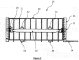
- the concrete crash block 17 has at least one pair of opposing side faces, which are also opposing side faces 18, 20 (See Figure 1 ) of the barrier island.
- External fixing elements 22 are provided on the opposing side faces 18, 20 of the concrete crash block 17.
- each external fixing element 22 is a U-bolt that, once the concrete crash block 17 has been cast, extends therefrom. Extending internally between the U-bolts 22 on the opposing faces are one or more load transfer element 24 which are embedded within the concrete crash block 17. Under load the load transfer elements 24 transfer load from the external fixing elements 22 on one side of the concrete crash block 17 to the external fixing elements 22 on the opposing side of said concrete crash block 17.
- the security barrier 10 In use, when the security barrier 10 is subject to sufficient impact to create tension in said flexible attachments 14, they transfer load between external fixing elements 22 of a barrier island without imparting a substantial tensile load on the concrete crash block 17.
- the concrete relatively, is weaker under tension, and due to the high forces that occur under impact, by passing the load through specially designated components, i.e. the load transfer elements 24, the concrete is not subject to the full tensile load of the impact as the flexible attachments 14 pull tight, which otherwise could result in one or both of the external fixing elements 22 pulling out, or the concrete fracturing between the external fixing elements 22.
- each load transfer element 24 is substantially parallel to the longitudinal axis of the security barrier 10 and is also substantially perpendicular to a direction of impact protection of the security barrier.
- direction of impact protection it is meant a direction from which the security barrier 10 is intended to prevent vehicular penetration.
- the opposing side faces 18, 20 each have at least one recess formed therein and an external fixing element 22 is located in each recess.
- each opposing side face 18, 20 has two recesses therein and an external fixing element 22 is located in each said recess.
- the recesses extend along the side faces 18, 20 to a lower edge thereof.
- one or more flexible attachment 14 which extends between external fixing elements 14 of adjacent barrier islands 12 passes from the external fixing element 14, along each said recess to the lower edge thereof, and spans the separation between said adjacent barrier islands 12 substantially along a surface on which the security barrier 10 is located. As described, above by passing the flexible attachment along the ground surface, unimpeded pedestrian access between the barrier islands 12 is enabled.
- each recess is formed by an impact bracket 25 which comprises a steel U-channel 26 extending vertically along each opposing side face 18, 20 from a lower edge thereof.
- the U-channel 26 becomes embedded in the concrete crash block so that it opens onto the side face.
- the ends and open face of the U-channel 26 may be covered, for example with a removable tape, to prevent the concrete from filling the U-channel 26.
- the U-bolts that form the external fixing elements 22 pass through holes that have been drilled in the U-channel 26 prior to casting, at a position above the lower edge thereof. In the example embodiment the holes for the U-bolt are vertically spaced and the lower hole is positioned 360mm from the lower edge of the barrier island 12.
- each U-bolt is then attached to the U-channel by welds 23 to hold them in place, although it will be appreciated that other methods of retaining them may be used.
- the two threaded ends of each U-bolt extend through the U-channel 26 and project from the rear surface thereof.
- a clamp plate 29 is passed over the projecting threaded ends and nuts 28 are applied to retain it in place.
- an attachment 31 of the load transfer element 24 is placed between the clamp plate 29 and the U-channel 26 such that when the nuts 28 are tightened the load transfer element 24 and the U-bolts are attached together.
- any tension applied to one U-bolt for example by the flexible attachment 14 pulling tight, is transferred from the flexible attachment 14, to the U-bolt, to the load transfer element 24 via the attachment 31, to the U-bolt on the opposing face and to the flexile attachment 14 attached to the opposing side face.
- the load transfer element 24 comprises a nylon webbing strap having a SWL of 4 tonnes. A small eye may be sewn on each end of the webbing strap through which the attachment 31, in the form of a metal ring, is located. The metal ring is passed between the U-bolt and the clamp plate as described above to attach the load transfer element 24 to each external fixing element 22.
- a single such load transfer element extends between each of a pair of external fixing elements 22 on one side face and a corresponding external fixing 22 element on the opposing side face.
- a single such nylon strap is used between opposing external fixing elements 22 it will be appreciated that multiple such nylon straps may be used between opposing external fixing elements 22, attached in the same manner.
- the load transfer elements 24 could be of any material having a suitable tensile strength, either rigid or flexible, for example other suitable material includes, without limitation: straps, cables or ropes made from metal such as steel, Kevlar, or other aramid or polymer fibres; solid metal rod or strips; and composite rods or strips.
- a hole is provided in either side of the U-channel 26 towards the lower edge thereof and a tube 30 extends therefrom substantially perpendicular thereto in either direction.
- the tube 30 has a long section 32 extending towards the centre of the crash block 12 and a short section 34 extending away from the centre of the crash block 12.
- the ends of the tubes are blanked of by plates welded thereto.
- the tubes 32, 34 may be stainless steel to prevent or minimise any corrosion thereof.
- a stainless-steel pin 36 is located in the long section 32 and is slidable therein such that in an extended position it spans the U-channel 26 such that it projects into the short section 34, and in a retracted position is substantially contained in the long section 32 such that it projects only a short distance therefrom.
- One or more grooves 38 may be cut into the pin 36 to create a weakened shear line intended to fracture under severe loading.
- the flexible attachment 14 passes behind the pin 36 to retain it in the recess until it is adjacent a lower end thereof, below which it may exit. Under impact, as a barrier island 10 moves, the flexible attachment 14 will pull tight against the pin 36 which will shear at the one or more grooves 38 thereby allowing the flexible attachments 14 to transfer force between external fixing elements 22 of adjacent barrier islands 12.
- a cover plate (not shown) may extend over the recesses to cover the flexible attachments 14 and external fixing elements 22.
- the internal structure of the barrier island 12 also includes a rebar cage 40 embedded within the concrete crash block 17 below the surface thereof.
- the rebar cage reinforces the concrete crash block and helps to prevent fracture of the concrete under impact.
- the barrier island 12 may have lifting points therein. These are formed as part of the internal structure 16 of the crash block by the provision of a first two lengths of box section 42 extending across the rebar cage 40 and protruding slightly from each side thereof.
- the two lengths of box section 42 are dimensioned so that they are the same length as the width of the formed barrier island 12.
- a second two lengths of box section 44 which may be substantially identical to the first two lengths of box section 42, may be located below the rebar cage. These second two lengths of box section 44, may form additional lifting points and/or additional fixing points for seats, benches or other furniture.
- the length of the first two lengths of box section 42 are such that they open onto opposing faces of the formed barrier island 12.
- a cover may be placed over the end of each length of box section 42 to prevent concrete entering therein during the casting of the concrete around the internal structure 16.
- the cover may be a bespoke cover or may for example simply be a temporary cover made of tape. After the concrete is cast the covers are removed and either disposed of or used in the fabrication of further security barriers.
- the second two lengths of box section 44 may be arranged in a similar manner.
- a barrier island barrier of the invention may have two pairs of opposing side faces having external fixing elements 22 on opposing side faces of each pair between which one or more load transfer element 24 extends.
- Such a barrier island may for example be used where it is required for the security barrier 10 to form a corner. In this manner the barrier can be continuous at the corner without losing the technical benefit of the invention.
- the barrier island 12 has additional internal structure as shown in Figures 8 and 9 .
- the internal structure is substantially encased in cast concrete.
- EN206-1:2000 C30 grade concrete was used (i.e. a concrete for which the minimum compressive strength of a 300mm long, 150mm diameter cylinder is 30N/mm 2 ) and the aggregate was 10mm sized.
- the additional internal structure of the barrier island 12 comprises a first and second layer of pieces of metallic ballast which are in the form of steel blocks 46 located between a top face 48 and a bottom face 50 (see Figure 1 ) of the barrier island 12.
- the first layer comprises a first array of blocks and the second layer comprises a second array of blocks.
- the steel blocks 46 may comprise solid pieces of steel billet or may each comprise a plurality of strips of steel, placed adjacent one another or attached together.
- the barrier island 12 can have a mass in the range of 7.5 tonnes to 8.5 tonnes of which at least 5.5 tonnes are ballast.
- the steel blocks 46 have a mass of 6000kg (+/- 10%) and the barrier island has a mass of 8000kg (+/- 10%).
- the pieces of metallic ballast forming the first layer may have a greater mass than the pieces of metallic ballast forming the second layer.
- the first layer of steel blocks may account for in excess of 60% of the mass of the metallic ballast, optionally in excess of 70% or 80%. This biasing may be achieved by using different sizes of pieces of metallic ballast in each layer, a different number of pieces of metallic ballast in each layer, or different densities of metallic ballast (i.e. different metals or alloys) in each layer. By biasing the mass of the ballast, which has a greater density than the matrix, towards the bottom of the security barrier the stability of the barrier is increased under impact.
- the steel blocks 46 are substantially surrounded by the rebar cage 40 that extends below, above and around the array of steel blocks 46 and substantially adjacent to, but beneath, the respective exterior surfaces of the cast concrete that surrounds the internal structure 16. Although shown as a rectangular array, the steel blocks 46 may alternatively be arranged in a linear array, or irregularly. It will also be appreciated that although shown as rectangular blocks, alternative shaped pieces of metallic ballast can be used as described in more detail below.
- the steel blocks 46 are arranged in spaced relationship to one another such that, when encased in the cast concrete, the concrete passes around and between them in a continuous structure.
- the additional mass achieved by using the metal ballast increases the resistance of the barrier islands to movement under impact.
- a rebar cage 40 as shown in Figures 10 to 12 is used.
- the cage is made of 16mm rebar and has overall dimensions of 1900mm long, 1100mm wide and 732m high.
- the rebar cage 40 is made in three parts for convenience, although may be made in fewer or more parts.
- a first part 52 comprises a lower face 54, and three side faces 56, 58, 60 leaving one side face and the top face open.
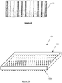
- a plurality of feet 62 extend downward from the lower face 54 to, during manufacture, allow the cast concrete to fill a space below the rebar cage 40.
- the first part 52 may be fabricated by any known method, for example it may be fabricated by welding, brazing or tying the rebar together.
- the plurality of feet 62 may, after the barrier island 12 is formed, extend outwardly from the lower surface of the barrier island. This may be achieved by, during manufacture, placing a sheet beneath the rebar cage 40 through which the feet 62 extend so that after cast concrete is poured to form the barrier island 12 there is a space into which the concrete does not flow such that once the concrete is set the feet 62 extend therefrom.
- the feet may project in the region of 1 to 10mm, optionally in the region of 3 to 5mm.
- the feed will, under impact, act as "teeth" and provide very high pressure contact points which, if the barrier island 12 moves as a result of an impact, will dig into the surface on which it is situated, further impeding the movement thereof.
- a hard surface for example concrete or tarmacadam
- the feet 62 are tapered towards their outer ends to reduce the surface area of contact between the feet and the surface on which it is resting, thereby increasing the pressure at each foot.
- Rubber or plastic caps can optionally be fitted over the projecting metal feet 62. In use this allows the barrier islands 12 to be positioned and repositioned, by lifting and moving, on surfaces without the feet 62 causing damage. If, however, in use a barrier island 12 is struck, e.g. by a vehicle, with sufficient force to move it the pressure on the feet 62 will result in the caps being broken or torn off allowing the metal feet 62 to dig into the surface and further impede movement of the barrier island 12.
- the steel blocks 46 and the lengths of box section 42 can then be located in the first part 52 of the rebar cage 40.
- the remaining two faces being a top face 64 ( Figure 11 ) and a side face 66 ( Figure 12 ) of the rebar cage 40 are added and fixed in place for example by welding, brazing or tying.
- the remaining two faces 64, 66 may be added individually or may be formed and added as a single component.
- the anti-skid plate 68 comprises a tray structure 70 and a plurality of feet 62a.
- the tray structure is welded from 10mm mild steel and has overall dimensions to accept the barrier island 12 therein within the upstanding walls thereof.
- a plurality of holes are drilled in the steel plate and 20mm steel feet 62a are passed through and welded flush with the upper surface thereof so that they project 10mm from the lower surface of the tray structure 70.
- the manufactured barrier island 12 is then lowered into the anti-skid plate 68 and grout is applied around the edge to retain the barrier island 12 in the place.
- the barrier island 12 may be retained in the anti-skid plate 68 by screws or bolts.
- rubber or plastic caps may be attached to the bottom of the feet 62a.
- the metallic ballast may be an alternative metal to steel, for example it may be any metal having a similar or greater density.
- the metallic ballast may be provided in an alternative form to steel bars.
- the metallic ballast may comprise small pieces of scrap metal (e.g. steel), for example small metal discs (or similar shape) that are produced as scrap from the punching of holes in sheet metal.
- the small pieces may be set in a binder to hold them together, for example cement or a resin binder. Alternatively, they may be placed in containers, e.g. sheet metal troughs.
- the ballast may comprise irregular shaped pieces of metal.
- the ballast may comprise small pieces of metal, for example metal shot, metal discs, or the like, mixed with the concrete prior to casting the security barrier.
- ballast as described hereinabove is an optional feature of one embodiment and the barrier islands of the invention and may be omitted in other embodiments of the invention.
- FIG. 14 shows the internal metal stricture of the barrier island which comprises a rebar cage 40, lifting points comprising two lengths of rectangular box section steel 42, and impact brackets 25 as described hereinabove. It will be appreciated that prior to casting the barrier island load transfer elements 24 (not shown) would be attached to the impact brackets a described above.
- four fence post sockets 72 are located one at each corner of the metal structure at a position that when the barrier island is cast they open onto the upper surface thereof.
- the fence post sockets are made of steel box section and may be temporarily capped at their upper end during manufacture to prevent concrete ingress during casting, however it will be appreciated that other shaped fence post sockets, for example rectangular or round could also be used.
- a security post footing 74 as described in GB 2511273 is provided centrally in the structure, again located such that when the barrier island is cast it opens onto the upper surface thereof.
- Figure 15 shows the case barrier island 12 formed by casting concrete around the structure of Figure 14 so that it becomes embedder therein with the fence post sockets 72 and the security post footing 74 opening at the upper surface thereof.
- a barrier island 12 as shown in Figure 15 is shown in with fence posts 76 are inserted into the fence post sockets 72 and support posts 78 are attached to the fence posts 76 by fence spacers 80. In this way a support for a fence may be provided that extends to the ground.
- the fence posts 76 and support posts 78 may just be provided on one side of the barrier island 12.
- a security post footing 74 is provided in the barrier island it is fitted with spring steel security posts 82.
- the security posts 82 can act to increase the effective height of the barrier island 12, however for enhanced protection in some applications it may be appropriate to connect security posts 82 of adjacent barrier islands 12 with one or more steel cables 84, for example as described in WO 2015/033100 .
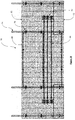
- the security barrier comprises a plurality of barrier islands 12 as described in relation to Figures 14 and 15 above. As can be seen the barrier islands are attached to one another by flexible attachments 14 as described above in relation to Figures 1 and 2 .
- the barrier island spacing is nominally 1200mm to allow for pedestrian passage but to prevent vehicular passage.
- a larger separation is provided by two adjacent barrier islands 12 (the central barrier islands in the illustrated example), each of which has a security post 82 provided in the security post footing 74 thereof.
- An exemplary separation of 8000mm is used in the illustrated embodiment, however different sized separations may be used provided they are sufficiently wide to allow the passage of the intended vehicles.
- a cable 84 is extended across the security posts 82 to prevent the passage of vehicles. When vehicular access is required the cable can be removed.
- a pivotable solid barrier for example a steel barrier, optionally a spring steel barrier, may extend between the security posts 82.
- a security barrier 10 comprising adjacent barrier islands 12 as described in relation to Figures 14 to 16 , connected by flexible attachments 14 (not shown) and having a fence post 76 located in each said fence socket 72 one side of the security barrier 10 and extending substantially vertically therefrom.
- Attached at one end to each fence post 76 is a pair of fence spacers 80.
- the fence spacers 80 are each attached at their other end to a support post 78 to which a fence panel 86 is attached.
- the support post 78 and the fence spacers 80 the fence panel 86 is attached to the fence posts 76 located in the fence sockets 72 of barrier island 12.
- fence panel 86 could be attached directly to the fence posts 76 the described arrangement enables the fence panels 86 to be located forward of the security barrier 10 so that they do not interfere therewith. Additional longitudinal fence braces 88 are provided extending between the support posts 78 of adjacent barrier islands 12. Although two barrier islands 12 are shown it will be appreciated that any number of the barriers islands 12 may be used to form a continuous fence.
- the fence panel 86 may be attached by means of simple U-bolts or other easily attachable and releasable connectors, for example zip ties. This design enables a fence to quickly be erected on the barrier islands 12 that can then provide a single, or double, pedestrian barrier as well as a vehicular barrier.
- spring steel security posts 82 are provided in the embedded security post footings 74 and a plurality of wires 84 as described in WO 2015/033100 are attached between the security posts 82 of adjacent barrier islands, thereby further inhibiting vehicular passage, while allowing for a greater spacing between the security barriers
- Figure 19 a variation of the embodiment of Figure 18 is shown. In this arrangement a central section of the fence panel is split in the middle and is pivotally attached to the support posts 78 at either side to form two parts 90, 92 of an openable gate in the fence.
- spring steel security posts 82 are provided in the embedded security post footings 74 of the barrier islands 12 on either side of the gate and a barrier is formed therebetween.
- a solid barrier 94 pivotal about one end, is provided between the security posts 82.
- a security barrier 10 is provided that prevents both vehicular and pedestrian access but which can be selectively opened to allow passage of both pedestrians and vehicles therethrough hen access is required.
- the security barrier 10 of the example embodiment was designed and manufactured to meet the requirements of the BSI IWA14.2013 collision test. In the test the security barrier 10 is placed on top of the test surface (flat concrete) without any attachment thereto or any foundations and a 7.5 tonne truck is then collided with the security barrier 10 travelling at 64kph (40mph).
Landscapes
- Engineering & Computer Science (AREA)
- Architecture (AREA)
- Civil Engineering (AREA)
- Structural Engineering (AREA)
- General Engineering & Computer Science (AREA)
- Refuge Islands, Traffic Blockers, Or Guard Fence (AREA)
- Manufacturing Of Tubular Articles Or Embedded Moulded Articles (AREA)
Claims (15)
- Barrière de sécurité à montage en surface (10) comprenant :une pluralité d'îlots de barrière (12) disposés en relation espacée les uns par rapport aux autres, chaque îlot de barrière (12) comprenant : un bloc de collision en béton (17) comportant au moins une paire de faces latérales opposées (18, 20) ; des éléments de fixation externes (22) sur lesdites faces latérales opposées du bloc de collision en béton (17), et un ou plusieurs éléments de transfert de charge (24) intégrés intérieurement au sein dudit bloc de collision en béton (17) ; etune ou plusieurs pièces d'attachement (14) s'étendant entre des éléments de fixation externes (22) d'îlots de barrière adjacentsdans laquelle, sous charge, lesdits éléments de transfert de charge (24) transfèrent la charge à travers le bloc de collision en béton (17) depuis les éléments de fixation externes (22) sur un côté dudit bloc de collision en béton (17) vers les éléments de fixation externes (22) sur le côté opposé (20) dudit bloc de collision en béton (17) ; etcaractérisée en ce que lesdites pièces d'attachement (14) sont des pièces d'attachement flexibles qui, lors de l'utilisation, s'étendent sensiblement le long du sol entre lesdits îlots de barrière (12) adjacents.
- Barrière de sécurité à montage en surface (10) selon la revendication 1, dans laquelle lesdits éléments de transfert de charge (24) sont attachés à chaque extrémité à un dit élément de fixation externe (22).
- Barrière de sécurité à montage en surface (10) selon la revendication 1 ou 2, dans laquelle ledit bloc de collision en béton (17) comprend deux paires de faces latérales opposées, et dans laquelle un ou plusieurs éléments de transfert de charge (24) s'étendent entre des éléments de fixation externes (22) sur les faces latérales opposées de chaque dite paire.
- Barrière de sécurité à montage en surface (10) selon l'une quelconque des revendications précédentes, dans laquelle lesdites faces latérales opposées (18, 20) présentent au moins un évidement et ledit élément de fixation externe (22) se trouve dans ledit évidement, ou dans laquelle lesdites faces latérales opposées (18, 20) présentent chacune deux évidements et un élément de fixation externe (22) se trouve dans chacun desdits évidements.
- Barrière de sécurité à montage en surface (10) selon la revendication 4, dans laquelle chacun desdits évidements s'étend le long de ladite face latérale opposée (18, 20) jusqu'à un bord inférieur de celle-ci.
- Barrière de sécurité à montage en surface (10) selon l'une quelconque des revendications 4 ou 5, dans laquelle chaque dit évidement comprend un canal en U métallique (26) s'étendant verticalement le long d'une dite face latérale opposée (18, 20) depuis un bord inférieur de celle-ci, ledit canal en U (26) étant intégré dans ledit bloc de collision en béton (17) et s'ouvrant sur ladite face latérale (18, 20), et dans laquelle ledit élément de fixation externe (22) s'étend à travers ledit canal en U (26) jusqu'à une position au-dessus dudit bord inférieur.
- Barrière de sécurité à montage en surface (10) selon la revendication 5 ou 6, dans laquelle lesdites une ou plusieurs pièces d'attachement (14) passent le long de chaque dit évidement jusqu'au bord inférieur et couvrent une séparation entre lesdits îlots de barrière (12) adjacents à partir de celle-ci.
- Barrière de sécurité à montage en surface (10) selon la revendication 7, comprenant en outre une broche (38) s'étendant à travers ledit évidement sensiblement adjacent au bord inférieur, et dans laquelle ladite pièce d'attachement flexible (14) passe derrière ladite broche (38).
- Barrière de sécurité à montage en surface (10) selon la revendication 6 et la revendication 8, comprenant en outre un trou dans ledit canal en U (26) et un tube (30) s'étendant à partir de celui-ci, dans laquelle ladite broche (38) peut coulisser dans ledit tube (30) à travers ledit trou.
- Barrière de sécurité à montage en surface (10) selon l'une quelconque des revendications précédentes, dans laquelle chacun desdits éléments de transfert de charge (24) et/ou chaque dite pièce d'attachement (22) comprend une ou plusieurs sangles en nylon.
- Barrière de sécurité à montage en surface (10) selon l'une quelconque des revendications précédentes, comprenant en outre un ballast métallique (46) à l'intérieur dudit bloc de collision en béton (17).
- Barrière de sécurité à montage en surface (10) selon l'une quelconque des revendications précédentes, comprenant un ou plusieurs points de levage intégrés dans celle-ci, dans laquelle lesdits points de levage comprennent deux ou plusieurs sections de caisson (42) s'étendant à travers le bloc de collision en béton (17) et s'ouvrant sur les surfaces opposées de celui-ci.
- Barrière de sécurité à montage en surface (10) selon l'une quelconque des revendications précédentes, comprenant en outre un ou plusieurs trous de poteau de clôture (72) s'étendant vers le bas dans une surface supérieure de chaque îlot de barrière (12).
- Barrière de sécurité à montage en surface (10) selon l'une quelconque des revendications précédentes, comprenant en outre une ou plusieurs semelles de poteau de sécurité (74) s'étendant vers le bas dans une surface supérieure de celle-ci, ladite semelle de poteau de sécurité (74) étant destinée à recevoir un poteau de sécurité (82) lors de l'utilisation.
- Barrière de sécurité à montage en surface (10) selon la revendication 13 ou 14 dépendant de la revendication 13, comprenant en outre :un poteau de clôture (76) se trouvant dans un ou plusieurs trous de poteau de clôture (72) dans des îlots de barrière (12) adjacents, et : au moins un panneau de clôture (86) attaché aux poteaux de clôture (76) desdits îlots de barrière (12) adjacents, ou au moins une porte ouvrable (90, 92) attachée auxdits poteaux de clôture (76) desdits îlots de barrière adjacents ; etun poteau de sécurité en acier à ressort (82) se trouvant dans la semelle de poteau de sécurité (74) des îlots de barrière (12) adjacents et une autre barrière de sécurité comprenant soit une ou plusieurs barrières flexibles (84) soit une barrière rigide (94) s'étendant entre les poteaux de sécurité (82) desdits îlots de barrière (12) adjacents, et dans laquelle ladite barrière flexible (84) ou rigide (94) est soit attachée de façon permanente auxdits poteaux de sécurité (82), soit peut être détachée desdits poteaux de sécurité (82) pour créer une barrière ouvrable.
Applications Claiming Priority (3)
| Application Number | Priority Date | Filing Date | Title |
|---|---|---|---|
| GB1714029.4A GB2566062A (en) | 2017-09-01 | 2017-09-01 | Surface mount security barrier |
| GB1720795.2A GB2566126A (en) | 2017-09-01 | 2017-12-13 | Surface mount security barrier |
| PCT/EP2018/073411 WO2019043132A1 (fr) | 2017-09-01 | 2018-08-30 | Barrière de sécurité à montage en surface |
Publications (2)
| Publication Number | Publication Date |
|---|---|
| EP3676452A1 EP3676452A1 (fr) | 2020-07-08 |
| EP3676452B1 true EP3676452B1 (fr) | 2021-08-11 |
Family
ID=60050773
Family Applications (2)
| Application Number | Title | Priority Date | Filing Date |
|---|---|---|---|
| EP18765827.3A Active EP3676451B1 (fr) | 2017-09-01 | 2018-08-30 | Barrière de sécurité à montage en surface |
| EP18762509.0A Active EP3676452B1 (fr) | 2017-09-01 | 2018-08-30 | Barrière de sécurité à montage en surface |
Family Applications Before (1)
| Application Number | Title | Priority Date | Filing Date |
|---|---|---|---|
| EP18765827.3A Active EP3676451B1 (fr) | 2017-09-01 | 2018-08-30 | Barrière de sécurité à montage en surface |
Country Status (5)
| Country | Link |
|---|---|
| US (2) | US20200362524A1 (fr) |
| EP (2) | EP3676451B1 (fr) |
| AU (2) | AU2018322836B2 (fr) |
| GB (5) | GB2566062A (fr) |
| WO (2) | WO2019043132A1 (fr) |
Families Citing this family (2)
| Publication number | Priority date | Publication date | Assignee | Title |
|---|---|---|---|---|
| GB2598908B (en) * | 2020-09-17 | 2023-05-10 | Andrew Stone Mark | Hostile vehicle mitigation system |
| CN113370867A (zh) * | 2021-06-25 | 2021-09-10 | 北京安龙科技集团有限公司 | 液压钩臂式设障车及操作方法 |
Family Cites Families (69)
| Publication number | Priority date | Publication date | Assignee | Title |
|---|---|---|---|---|
| US817282A (en) * | 1906-02-10 | 1906-04-10 | David C Stewart | Composition fence-post. |
| US3540699A (en) * | 1966-06-14 | 1970-11-17 | Alberto Guzzardella | Hydraulic barrier structure for roadways |
| US4328955A (en) * | 1980-03-10 | 1982-05-11 | Hermans Albert L | Defensive personnel barrier |
| US4406563A (en) * | 1981-03-30 | 1983-09-27 | Urlberger Hermann Hans | Protective barrier provided with at least one longitudinal side bar |
| SE8103419L (sv) * | 1981-06-01 | 1982-12-02 | Almer Bengt Oennert | Anordning vid betongblock |
| US4553875A (en) * | 1982-04-01 | 1985-11-19 | Casey Steven M | Method for making barrier structure |
| US4769191A (en) * | 1984-04-26 | 1988-09-06 | Silvio Diana | Monolithic surface ornamentation of pre-cast reinforced concrete wall |
| FR2610338A1 (fr) | 1987-02-03 | 1988-08-05 | Giraud Paul | Dispositif pour barrage routier a volumes pyramidaux |
| US4806044A (en) | 1988-05-20 | 1989-02-21 | Barrier Systems, Inc. | Anti-crash lane barrier with self-centering hinges |
| DE59102049D1 (de) * | 1990-04-18 | 1994-08-04 | Sps Schutzplanken Gmbh | Schutzplankeneinrichtung für Verkehrsflächen, insbesondere zur Sicherung von Baustellen. |
| US5156485A (en) * | 1991-04-25 | 1992-10-20 | Texas A & M University | Low profile concrete road barrier |
| DE9301089U1 (de) * | 1993-01-27 | 1993-03-25 | Stewing Beton- und Fertigteilwerk GmbH & Co. KG, 6096 Raunheim | Verkehrsleitstein |
| US6662520B1 (en) * | 1993-06-28 | 2003-12-16 | Thomas Page Nelson | Sub-rigid fast-form barrier system |
| US5387049A (en) * | 1993-06-29 | 1995-02-07 | Barrier Systems, Inc. | Roadway barrier module, system and method |
| US5651635A (en) * | 1995-04-24 | 1997-07-29 | Schuylkill Products, Inc. | Concrete barrier with reinforcement |
| US5605413A (en) * | 1995-06-26 | 1997-02-25 | Brown; James C. | Highway barricade |
| FR2756301B1 (fr) | 1996-11-26 | 1998-12-31 | Serravalle Joseph Ets | Barriere mobile et ensemble forme par assemblage d'une pluralite de telles barrieres |
| US5938370A (en) * | 1998-09-23 | 1999-08-17 | Gzybowski; Michael S. | Safety barrier with passageway |
| NL1012439C2 (nl) * | 1999-06-25 | 2001-01-10 | Haitsma Beton Bv | Afscheidingselement. |
| JP2001164530A (ja) * | 1999-12-06 | 2001-06-19 | Taisei Corp | コンクリート製の道路用防護壁及び道路用防護壁の製造方法 |
| US20030190189A1 (en) * | 2001-04-13 | 2003-10-09 | Sentry Protection Products, Inc. | Apparatus for protecting structural supports |
| US6474904B1 (en) | 2001-09-24 | 2002-11-05 | Barrier Systems, Inc. | Traffic barrier with liquid filled modules |
| US20030086761A1 (en) * | 2001-11-07 | 2003-05-08 | Anderson Darrys Rhett | Multi-purpose precast barrier |
| CA2364937A1 (fr) | 2001-12-12 | 2003-06-12 | Randal Bablitz | Systeme de barrieres raccordables |
| US20030185629A1 (en) * | 2002-04-02 | 2003-10-02 | Yodock Leo J. | Floating barrier wall |
| GB2406127A (en) * | 2003-09-17 | 2005-03-23 | Hill & Smith Holdings Plc | Road safety barriers |
| GB2407837B (en) * | 2003-11-04 | 2007-07-11 | Corus Uk Ltd | Traffic control barriers |
| US7040836B2 (en) * | 2004-05-04 | 2006-05-09 | Rock Twelve Security Architecture | Turntable barrier system |
| US7128496B2 (en) * | 2004-07-21 | 2006-10-31 | Rock Twelve, Llc | Vehicle barrier system |
| US7699558B2 (en) * | 2004-07-26 | 2010-04-20 | Rsa Protective Technologies, Llc | Anti-ram system and method of installation |
| US7144186B1 (en) * | 2004-09-28 | 2006-12-05 | Kontek Industries, Inc. | Massive security barrier |
| US7775738B2 (en) * | 2004-10-22 | 2010-08-17 | Darcy Daniel T | Vehicle barrier system |
| US7931422B2 (en) * | 2005-09-21 | 2011-04-26 | Traffix Devices, Inc. | Water-ballasted protection barrier |
| US7416364B2 (en) * | 2006-03-03 | 2008-08-26 | Yodock Iii Leo J | Pivot unit for barrier devices |
| US8206056B2 (en) * | 2006-06-12 | 2012-06-26 | Patriot Barrier Systems, Llc | Barrier system |
| US7654768B1 (en) * | 2006-10-19 | 2010-02-02 | Kontek Industries, Inc. | Massive security barriers having tie-bars in tunnels |
| DE102006053341A1 (de) | 2006-11-10 | 2008-05-15 | Max Bögl Bauunternehmung GmbH & Co. KG | Betonleitwand |
| US8001880B2 (en) * | 2007-05-04 | 2011-08-23 | Defenshield, Inc. | Barrier |
| US9441337B2 (en) * | 2007-12-17 | 2016-09-13 | Michael John Lamore | Cable housing system |
| GB0810021D0 (en) * | 2008-06-02 | 2008-07-09 | Qinetiq Ltd | Apparatus and method for deploying a vehicle arrestign device |
| AT507611B1 (de) * | 2008-11-20 | 2010-08-15 | Mathias Mag Redlberger | Verbindungseinrichtung zum verbinden von trennelementen für verkehrsflächen |
| GB0901596D0 (en) * | 2009-01-31 | 2009-03-11 | Gerrard Robert | Post footing |
| DK2393986T3 (en) * | 2009-02-03 | 2016-12-19 | Traffix Devices Inc | Protection barrier with water ballast and method for preparation thereof |
| US20100272509A1 (en) * | 2009-04-27 | 2010-10-28 | Tri-State Construction, Inc. | Traffic barrier section |
| WO2010132616A1 (fr) * | 2009-05-12 | 2010-11-18 | Rsa Protective Technologies, Llc | Systèmes de sécurité anticollision de véhicule montés en surface |
| AT11483U1 (de) * | 2009-06-15 | 2010-11-15 | Kirchdorfer Fertigteilholding | Zugelement |
| AT508432B1 (de) * | 2009-06-22 | 2011-05-15 | Kirchdorfer Fertigteilholding Gmbh | Abschlusselement |
| US20120170982A1 (en) * | 2009-09-04 | 2012-07-05 | Beta Vision Products Australia Pty Ltd | Silt barrier |
| DE102009050266A1 (de) * | 2009-10-21 | 2011-05-05 | Heintzmann Sicherheitssysteme Gmbh & Co. Kg | Fahrzeugrückhaltesystem mit Beschwerungskörper |
| EP2339071B1 (fr) * | 2009-12-22 | 2015-04-15 | Strabag Ag | Elément de liaison et glissière de sécurité de voies de circulation |
| DE102010018843B4 (de) * | 2010-04-29 | 2016-04-14 | Heintzmann Sicherheitssysteme Gmbh & Co. Kg | Fahrzeugrückhaltesystem mit Beschwerungskörper |
| US9127421B2 (en) * | 2011-01-28 | 2015-09-08 | ATG Access Ltd. | Bollards |
| AU2012307080A1 (en) * | 2011-09-05 | 2014-03-20 | Okara Pty Ltd | Vehicle separation barrier |
| US8657526B2 (en) * | 2012-02-09 | 2014-02-25 | Engineered Arresting Systems Corporation | Vehicle arresting net |
| GB2511273B (en) | 2012-03-14 | 2017-07-12 | Gerrard Robert | Energy absorbing post with shallow footing |
| WO2014036237A1 (fr) * | 2012-09-01 | 2014-03-06 | Easi-Set Industries, Inc. | Structure de barrière d'autoroute à enclenchement |
| GB201221264D0 (en) | 2012-11-27 | 2013-01-09 | Highway Care Ltd | Barrier system |
| US8545126B1 (en) * | 2013-01-08 | 2013-10-01 | Abdulreidha Abdulrasoul AlSaffar | Portable traffic safety barrier |
| EA031974B1 (ru) * | 2013-01-14 | 2019-03-29 | Караблок Холдингс Лимитед | Заградительный блок |
| CA2915899A1 (fr) * | 2013-07-10 | 2015-01-15 | Saferoads Pty Ltd | Barriere routiere |
| WO2015023739A1 (fr) * | 2013-08-13 | 2015-02-19 | The Uab Research Foundation | Systèmes et procédés permettant de supporter des bornes d'interdiction |
| GB2532682B (en) | 2013-09-05 | 2020-10-07 | Gerrard Robert | Crash barrier |
| AT517351B1 (de) * | 2015-07-29 | 2017-01-15 | Kirchdorfer Fertigteilholding Gmbh | Notfallöffnungsleitwandelement |
| US10024008B2 (en) * | 2015-11-10 | 2018-07-17 | The United States Of America As Represented By The Secretary Of The Army | Expedient barrier apparatus |
| GB2552498B (en) * | 2016-07-25 | 2019-01-30 | Gerrard Robert | Surface mount security barrier |
| DE202017102967U1 (de) * | 2017-05-17 | 2017-07-18 | Obb Beton- Und Bau Gmbh | Mobile Betonsperre |
| US10844559B2 (en) * | 2018-04-27 | 2020-11-24 | Warning Lites Of Minnesota, Inc. | Traffic flow barrier with corresponding production mold and hand cart |
| WO2020087094A2 (fr) * | 2018-10-22 | 2020-04-30 | Daniluk Joseph | Système de barrière modulaire étanche à l'eau, à interverrouillage, à remplissage automatique, empilable et multifonctionnel |
| US11210754B1 (en) * | 2020-08-25 | 2021-12-28 | Jerry Castelle | Business model for residential development of vacant abandoned landfills |
-
2017
- 2017-09-01 GB GB1714029.4A patent/GB2566062A/en not_active Withdrawn
- 2017-12-13 GB GB1720795.2A patent/GB2566126A/en not_active Withdrawn
- 2017-12-13 GB GB1720790.3A patent/GB2566125A/en not_active Withdrawn
-
2018
- 2018-08-30 EP EP18765827.3A patent/EP3676451B1/fr active Active
- 2018-08-30 AU AU2018322836A patent/AU2018322836B2/en active Active
- 2018-08-30 US US16/640,268 patent/US20200362524A1/en not_active Abandoned
- 2018-08-30 EP EP18762509.0A patent/EP3676452B1/fr active Active
- 2018-08-30 WO PCT/EP2018/073411 patent/WO2019043132A1/fr not_active Ceased
- 2018-08-30 US US16/640,389 patent/US11479934B2/en active Active
- 2018-08-30 GB GB1814143.2A patent/GB2567940B/en active Active
- 2018-08-30 AU AU2018322835A patent/AU2018322835B2/en active Active
- 2018-08-30 WO PCT/EP2018/073410 patent/WO2019043131A1/fr not_active Ceased
- 2018-08-30 GB GB1814144.0A patent/GB2567941B/en active Active
Also Published As
| Publication number | Publication date |
|---|---|
| GB2566125A (en) | 2019-03-06 |
| GB2566126A (en) | 2019-03-06 |
| GB201814143D0 (en) | 2018-10-17 |
| EP3676451B1 (fr) | 2021-12-15 |
| EP3676451A1 (fr) | 2020-07-08 |
| GB201720795D0 (en) | 2018-01-24 |
| GB201814144D0 (en) | 2018-10-17 |
| US11479934B2 (en) | 2022-10-25 |
| GB201720790D0 (en) | 2018-01-24 |
| US20200354908A1 (en) | 2020-11-12 |
| WO2019043131A1 (fr) | 2019-03-07 |
| GB2567941A (en) | 2019-05-01 |
| AU2018322836A1 (en) | 2020-03-19 |
| GB2567940A (en) | 2019-05-01 |
| WO2019043132A1 (fr) | 2019-03-07 |
| GB2567940B (en) | 2020-12-23 |
| AU2018322836B2 (en) | 2021-12-16 |
| EP3676452A1 (fr) | 2020-07-08 |
| GB201714029D0 (en) | 2017-10-18 |
| GB2566062A (en) | 2019-03-06 |
| AU2018322835A1 (en) | 2020-03-19 |
| GB2567941B (en) | 2020-09-02 |
| AU2018322835B2 (en) | 2021-10-28 |
| US20200362524A1 (en) | 2020-11-19 |
Similar Documents
| Publication | Publication Date | Title |
|---|---|---|
| US10233601B2 (en) | Crash barrier | |
| US6863264B2 (en) | Cable barrier and method of mounting same | |
| US9234323B2 (en) | Post footing | |
| EP3488051B1 (fr) | Barrière de sécurité à montage en surface | |
| US8616802B2 (en) | Security barrier posts, security barriers and methods of building security barriers | |
| AU2002211164A1 (en) | Cable barrier and method of mounting same | |
| EP3676452B1 (fr) | Barrière de sécurité à montage en surface | |
| US20100090185A1 (en) | Roadway guardrail system and hanger | |
| US20200270831A1 (en) | Energy-absorbing vehicle barrier system | |
| AU2008228092B2 (en) | Perimeter security barriers | |
| AU2006100679A4 (en) | Improved permanent road barrier system | |
| GB2499368A (en) | A temporary barrier assembly with barrier members and arrestor | |
| Hirsh | Vehicle barrier |
Legal Events
| Date | Code | Title | Description |
|---|---|---|---|
| STAA | Information on the status of an ep patent application or granted ep patent |
Free format text: STATUS: UNKNOWN |
|
| STAA | Information on the status of an ep patent application or granted ep patent |
Free format text: STATUS: THE INTERNATIONAL PUBLICATION HAS BEEN MADE |
|
| PUAI | Public reference made under article 153(3) epc to a published international application that has entered the european phase |
Free format text: ORIGINAL CODE: 0009012 |
|
| STAA | Information on the status of an ep patent application or granted ep patent |
Free format text: STATUS: REQUEST FOR EXAMINATION WAS MADE |
|
| 17P | Request for examination filed |
Effective date: 20200219 |
|
| AK | Designated contracting states |
Kind code of ref document: A1 Designated state(s): AL AT BE BG CH CY CZ DE DK EE ES FI FR GB GR HR HU IE IS IT LI LT LU LV MC MK MT NL NO PL PT RO RS SE SI SK SM TR |
|
| AX | Request for extension of the european patent |
Extension state: BA ME |
|
| DAV | Request for validation of the european patent (deleted) | ||
| DAX | Request for extension of the european patent (deleted) | ||
| GRAP | Despatch of communication of intention to grant a patent |
Free format text: ORIGINAL CODE: EPIDOSNIGR1 |
|
| STAA | Information on the status of an ep patent application or granted ep patent |
Free format text: STATUS: GRANT OF PATENT IS INTENDED |
|
| INTG | Intention to grant announced |
Effective date: 20210408 |
|
| GRAS | Grant fee paid |
Free format text: ORIGINAL CODE: EPIDOSNIGR3 |
|
| GRAA | (expected) grant |
Free format text: ORIGINAL CODE: 0009210 |
|
| STAA | Information on the status of an ep patent application or granted ep patent |
Free format text: STATUS: THE PATENT HAS BEEN GRANTED |
|
| RAP1 | Party data changed (applicant data changed or rights of an application transferred) |
Owner name: GME SPRINGS LIMITED |
|
| RIN1 | Information on inventor provided before grant (corrected) |
Inventor name: GERRARD, MARCUS Inventor name: GERRARD, ROBERT |
|
| AK | Designated contracting states |
Kind code of ref document: B1 Designated state(s): AL AT BE BG CH CY CZ DE DK EE ES FI FR GR HR HU IE IS IT LI LT LU LV MC MK MT NL NO PL PT RO RS SE SI SK SM TR |
|
| RBV | Designated contracting states (corrected) |
Designated state(s): AL AT BE BG CH CY CZ DE DK EE ES FI FR GR HR HU IE IS IT LI LT LU LV MC MK MT NL NO PL PT RO RS SE SI SK SM TR |
|
| REG | Reference to a national code |
Ref country code: CH Ref legal event code: EP |
|
| REG | Reference to a national code |
Ref country code: DE Ref legal event code: R096 Ref document number: 602018021735 Country of ref document: DE |
|
| REG | Reference to a national code |
Ref country code: IE Ref legal event code: FG4D Ref country code: AT Ref legal event code: REF Ref document number: 1419510 Country of ref document: AT Kind code of ref document: T Effective date: 20210915 |
|
| REG | Reference to a national code |
Ref country code: NL Ref legal event code: FP |
|
| REG | Reference to a national code |
Ref country code: LT Ref legal event code: MG9D |
|
| REG | Reference to a national code |
Ref country code: AT Ref legal event code: MK05 Ref document number: 1419510 Country of ref document: AT Kind code of ref document: T Effective date: 20210811 |
|
| PG25 | Lapsed in a contracting state [announced via postgrant information from national office to epo] |
Ref country code: SE Free format text: LAPSE BECAUSE OF FAILURE TO SUBMIT A TRANSLATION OF THE DESCRIPTION OR TO PAY THE FEE WITHIN THE PRESCRIBED TIME-LIMIT Effective date: 20210811 Ref country code: RS Free format text: LAPSE BECAUSE OF FAILURE TO SUBMIT A TRANSLATION OF THE DESCRIPTION OR TO PAY THE FEE WITHIN THE PRESCRIBED TIME-LIMIT Effective date: 20210811 Ref country code: FI Free format text: LAPSE BECAUSE OF FAILURE TO SUBMIT A TRANSLATION OF THE DESCRIPTION OR TO PAY THE FEE WITHIN THE PRESCRIBED TIME-LIMIT Effective date: 20210811 Ref country code: ES Free format text: LAPSE BECAUSE OF FAILURE TO SUBMIT A TRANSLATION OF THE DESCRIPTION OR TO PAY THE FEE WITHIN THE PRESCRIBED TIME-LIMIT Effective date: 20210811 Ref country code: HR Free format text: LAPSE BECAUSE OF FAILURE TO SUBMIT A TRANSLATION OF THE DESCRIPTION OR TO PAY THE FEE WITHIN THE PRESCRIBED TIME-LIMIT Effective date: 20210811 Ref country code: AT Free format text: LAPSE BECAUSE OF FAILURE TO SUBMIT A TRANSLATION OF THE DESCRIPTION OR TO PAY THE FEE WITHIN THE PRESCRIBED TIME-LIMIT Effective date: 20210811 Ref country code: BG Free format text: LAPSE BECAUSE OF FAILURE TO SUBMIT A TRANSLATION OF THE DESCRIPTION OR TO PAY THE FEE WITHIN THE PRESCRIBED TIME-LIMIT Effective date: 20211111 Ref country code: LT Free format text: LAPSE BECAUSE OF FAILURE TO SUBMIT A TRANSLATION OF THE DESCRIPTION OR TO PAY THE FEE WITHIN THE PRESCRIBED TIME-LIMIT Effective date: 20210811 Ref country code: NO Free format text: LAPSE BECAUSE OF FAILURE TO SUBMIT A TRANSLATION OF THE DESCRIPTION OR TO PAY THE FEE WITHIN THE PRESCRIBED TIME-LIMIT Effective date: 20211111 Ref country code: PT Free format text: LAPSE BECAUSE OF FAILURE TO SUBMIT A TRANSLATION OF THE DESCRIPTION OR TO PAY THE FEE WITHIN THE PRESCRIBED TIME-LIMIT Effective date: 20211213 |
|
| PG25 | Lapsed in a contracting state [announced via postgrant information from national office to epo] |
Ref country code: PL Free format text: LAPSE BECAUSE OF FAILURE TO SUBMIT A TRANSLATION OF THE DESCRIPTION OR TO PAY THE FEE WITHIN THE PRESCRIBED TIME-LIMIT Effective date: 20210811 Ref country code: LV Free format text: LAPSE BECAUSE OF FAILURE TO SUBMIT A TRANSLATION OF THE DESCRIPTION OR TO PAY THE FEE WITHIN THE PRESCRIBED TIME-LIMIT Effective date: 20210811 Ref country code: GR Free format text: LAPSE BECAUSE OF FAILURE TO SUBMIT A TRANSLATION OF THE DESCRIPTION OR TO PAY THE FEE WITHIN THE PRESCRIBED TIME-LIMIT Effective date: 20211112 |
|
| REG | Reference to a national code |
Ref country code: CH Ref legal event code: PL |
|
| REG | Reference to a national code |
Ref country code: BE Ref legal event code: MM Effective date: 20210831 |
|
| PG25 | Lapsed in a contracting state [announced via postgrant information from national office to epo] |
Ref country code: LI Free format text: LAPSE BECAUSE OF NON-PAYMENT OF DUE FEES Effective date: 20210831 Ref country code: DK Free format text: LAPSE BECAUSE OF FAILURE TO SUBMIT A TRANSLATION OF THE DESCRIPTION OR TO PAY THE FEE WITHIN THE PRESCRIBED TIME-LIMIT Effective date: 20210811 Ref country code: CH Free format text: LAPSE BECAUSE OF NON-PAYMENT OF DUE FEES Effective date: 20210831 |
|
| REG | Reference to a national code |
Ref country code: DE Ref legal event code: R097 Ref document number: 602018021735 Country of ref document: DE |
|
| PG25 | Lapsed in a contracting state [announced via postgrant information from national office to epo] |
Ref country code: SM Free format text: LAPSE BECAUSE OF FAILURE TO SUBMIT A TRANSLATION OF THE DESCRIPTION OR TO PAY THE FEE WITHIN THE PRESCRIBED TIME-LIMIT Effective date: 20210811 Ref country code: SK Free format text: LAPSE BECAUSE OF FAILURE TO SUBMIT A TRANSLATION OF THE DESCRIPTION OR TO PAY THE FEE WITHIN THE PRESCRIBED TIME-LIMIT Effective date: 20210811 Ref country code: RO Free format text: LAPSE BECAUSE OF FAILURE TO SUBMIT A TRANSLATION OF THE DESCRIPTION OR TO PAY THE FEE WITHIN THE PRESCRIBED TIME-LIMIT Effective date: 20210811 Ref country code: MC Free format text: LAPSE BECAUSE OF FAILURE TO SUBMIT A TRANSLATION OF THE DESCRIPTION OR TO PAY THE FEE WITHIN THE PRESCRIBED TIME-LIMIT Effective date: 20210811 Ref country code: LU Free format text: LAPSE BECAUSE OF NON-PAYMENT OF DUE FEES Effective date: 20210830 Ref country code: EE Free format text: LAPSE BECAUSE OF FAILURE TO SUBMIT A TRANSLATION OF THE DESCRIPTION OR TO PAY THE FEE WITHIN THE PRESCRIBED TIME-LIMIT Effective date: 20210811 Ref country code: CZ Free format text: LAPSE BECAUSE OF FAILURE TO SUBMIT A TRANSLATION OF THE DESCRIPTION OR TO PAY THE FEE WITHIN THE PRESCRIBED TIME-LIMIT Effective date: 20210811 Ref country code: AL Free format text: LAPSE BECAUSE OF FAILURE TO SUBMIT A TRANSLATION OF THE DESCRIPTION OR TO PAY THE FEE WITHIN THE PRESCRIBED TIME-LIMIT Effective date: 20210811 |
|
| PLBE | No opposition filed within time limit |
Free format text: ORIGINAL CODE: 0009261 |
|
| STAA | Information on the status of an ep patent application or granted ep patent |
Free format text: STATUS: NO OPPOSITION FILED WITHIN TIME LIMIT |
|
| 26N | No opposition filed |
Effective date: 20220512 |
|
| PG25 | Lapsed in a contracting state [announced via postgrant information from national office to epo] |
Ref country code: IT Free format text: LAPSE BECAUSE OF FAILURE TO SUBMIT A TRANSLATION OF THE DESCRIPTION OR TO PAY THE FEE WITHIN THE PRESCRIBED TIME-LIMIT Effective date: 20210811 Ref country code: IE Free format text: LAPSE BECAUSE OF NON-PAYMENT OF DUE FEES Effective date: 20210830 Ref country code: BE Free format text: LAPSE BECAUSE OF NON-PAYMENT OF DUE FEES Effective date: 20210831 |
|
| PG25 | Lapsed in a contracting state [announced via postgrant information from national office to epo] |
Ref country code: SI Free format text: LAPSE BECAUSE OF FAILURE TO SUBMIT A TRANSLATION OF THE DESCRIPTION OR TO PAY THE FEE WITHIN THE PRESCRIBED TIME-LIMIT Effective date: 20210811 |
|
| PG25 | Lapsed in a contracting state [announced via postgrant information from national office to epo] |
Ref country code: FR Free format text: LAPSE BECAUSE OF NON-PAYMENT OF DUE FEES Effective date: 20211011 |
|
| PG25 | Lapsed in a contracting state [announced via postgrant information from national office to epo] |
Ref country code: CY Free format text: LAPSE BECAUSE OF FAILURE TO SUBMIT A TRANSLATION OF THE DESCRIPTION OR TO PAY THE FEE WITHIN THE PRESCRIBED TIME-LIMIT Effective date: 20210811 |
|
| PG25 | Lapsed in a contracting state [announced via postgrant information from national office to epo] |
Ref country code: HU Free format text: LAPSE BECAUSE OF FAILURE TO SUBMIT A TRANSLATION OF THE DESCRIPTION OR TO PAY THE FEE WITHIN THE PRESCRIBED TIME-LIMIT; INVALID AB INITIO Effective date: 20180830 |
|
| PG25 | Lapsed in a contracting state [announced via postgrant information from national office to epo] |
Ref country code: MK Free format text: LAPSE BECAUSE OF FAILURE TO SUBMIT A TRANSLATION OF THE DESCRIPTION OR TO PAY THE FEE WITHIN THE PRESCRIBED TIME-LIMIT Effective date: 20210811 |
|
| PG25 | Lapsed in a contracting state [announced via postgrant information from national office to epo] |
Ref country code: MT Free format text: LAPSE BECAUSE OF FAILURE TO SUBMIT A TRANSLATION OF THE DESCRIPTION OR TO PAY THE FEE WITHIN THE PRESCRIBED TIME-LIMIT Effective date: 20210811 |
|
| PGFP | Annual fee paid to national office [announced via postgrant information from national office to epo] |
Ref country code: NL Payment date: 20250821 Year of fee payment: 8 |
|
| PGFP | Annual fee paid to national office [announced via postgrant information from national office to epo] |
Ref country code: DE Payment date: 20250820 Year of fee payment: 8 |
|
| PG25 | Lapsed in a contracting state [announced via postgrant information from national office to epo] |
Ref country code: TR Free format text: LAPSE BECAUSE OF FAILURE TO SUBMIT A TRANSLATION OF THE DESCRIPTION OR TO PAY THE FEE WITHIN THE PRESCRIBED TIME-LIMIT Effective date: 20210811 |