EP3676464B1 - Dispositif de fixation pour matériau d'isolation - Google Patents
Dispositif de fixation pour matériau d'isolation Download PDFInfo
- Publication number
- EP3676464B1 EP3676464B1 EP18759320.7A EP18759320A EP3676464B1 EP 3676464 B1 EP3676464 B1 EP 3676464B1 EP 18759320 A EP18759320 A EP 18759320A EP 3676464 B1 EP3676464 B1 EP 3676464B1
- Authority
- EP
- European Patent Office
- Prior art keywords
- fastener
- thread
- nut
- section
- tip
- Prior art date
- Legal status (The legal status is an assumption and is not a legal conclusion. Google has not performed a legal analysis and makes no representation as to the accuracy of the status listed.)
- Active
Links
Images


Classifications
-
- F—MECHANICAL ENGINEERING; LIGHTING; HEATING; WEAPONS; BLASTING
- F16—ENGINEERING ELEMENTS AND UNITS; GENERAL MEASURES FOR PRODUCING AND MAINTAINING EFFECTIVE FUNCTIONING OF MACHINES OR INSTALLATIONS; THERMAL INSULATION IN GENERAL
- F16B—DEVICES FOR FASTENING OR SECURING CONSTRUCTIONAL ELEMENTS OR MACHINE PARTS TOGETHER, e.g. NAILS, BOLTS, CIRCLIPS, CLAMPS, CLIPS OR WEDGES; JOINTS OR JOINTING
- F16B25/00—Screws that cut thread in the body into which they are screwed, e.g. wood screws
- F16B25/0036—Screws that cut thread in the body into which they are screwed, e.g. wood screws characterised by geometric details of the screw
- F16B25/0042—Screws that cut thread in the body into which they are screwed, e.g. wood screws characterised by geometric details of the screw characterised by the geometry of the thread, the thread being a ridge wrapped around the shaft of the screw
- F16B25/0057—Screws that cut thread in the body into which they are screwed, e.g. wood screws characterised by geometric details of the screw characterised by the geometry of the thread, the thread being a ridge wrapped around the shaft of the screw the screw having distinct axial zones, e.g. multiple axial thread sections with different pitch or thread cross-sections
- F16B25/0063—Screws that cut thread in the body into which they are screwed, e.g. wood screws characterised by geometric details of the screw characterised by the geometry of the thread, the thread being a ridge wrapped around the shaft of the screw the screw having distinct axial zones, e.g. multiple axial thread sections with different pitch or thread cross-sections with a non-threaded portion on the shaft of the screw
-
- E—FIXED CONSTRUCTIONS
- E04—BUILDING
- E04D—ROOF COVERINGS; SKY-LIGHTS; GUTTERS; ROOF-WORKING TOOLS
- E04D3/00—Roof covering by making use of flat or curved slabs or stiff sheets
- E04D3/36—Connecting; Fastening
- E04D3/3601—Connecting; Fastening of roof covering supported by the roof structure with interposition of a insulating layer
- E04D3/3603—Connecting; Fastening of roof covering supported by the roof structure with interposition of a insulating layer the fastening means being screws or nails
-
- F—MECHANICAL ENGINEERING; LIGHTING; HEATING; WEAPONS; BLASTING
- F16—ENGINEERING ELEMENTS AND UNITS; GENERAL MEASURES FOR PRODUCING AND MAINTAINING EFFECTIVE FUNCTIONING OF MACHINES OR INSTALLATIONS; THERMAL INSULATION IN GENERAL
- F16B—DEVICES FOR FASTENING OR SECURING CONSTRUCTIONAL ELEMENTS OR MACHINE PARTS TOGETHER, e.g. NAILS, BOLTS, CIRCLIPS, CLAMPS, CLIPS OR WEDGES; JOINTS OR JOINTING
- F16B25/00—Screws that cut thread in the body into which they are screwed, e.g. wood screws
- F16B25/001—Screws that cut thread in the body into which they are screwed, e.g. wood screws characterised by the material of the body into which the screw is screwed
- F16B25/0021—Screws that cut thread in the body into which they are screwed, e.g. wood screws characterised by the material of the body into which the screw is screwed the material being metal, e.g. sheet-metal or aluminium
-
- F—MECHANICAL ENGINEERING; LIGHTING; HEATING; WEAPONS; BLASTING
- F16—ENGINEERING ELEMENTS AND UNITS; GENERAL MEASURES FOR PRODUCING AND MAINTAINING EFFECTIVE FUNCTIONING OF MACHINES OR INSTALLATIONS; THERMAL INSULATION IN GENERAL
- F16B—DEVICES FOR FASTENING OR SECURING CONSTRUCTIONAL ELEMENTS OR MACHINE PARTS TOGETHER, e.g. NAILS, BOLTS, CIRCLIPS, CLAMPS, CLIPS OR WEDGES; JOINTS OR JOINTING
- F16B25/00—Screws that cut thread in the body into which they are screwed, e.g. wood screws
- F16B25/10—Screws performing an additional function to thread-forming, e.g. drill screws or self-piercing screws
- F16B25/103—Screws performing an additional function to thread-forming, e.g. drill screws or self-piercing screws by means of a drilling screw-point, i.e. with a cutting and material removing action
-
- F—MECHANICAL ENGINEERING; LIGHTING; HEATING; WEAPONS; BLASTING
- F16—ENGINEERING ELEMENTS AND UNITS; GENERAL MEASURES FOR PRODUCING AND MAINTAINING EFFECTIVE FUNCTIONING OF MACHINES OR INSTALLATIONS; THERMAL INSULATION IN GENERAL
- F16B—DEVICES FOR FASTENING OR SECURING CONSTRUCTIONAL ELEMENTS OR MACHINE PARTS TOGETHER, e.g. NAILS, BOLTS, CIRCLIPS, CLAMPS, CLIPS OR WEDGES; JOINTS OR JOINTING
- F16B25/00—Screws that cut thread in the body into which they are screwed, e.g. wood screws
Definitions
- the present invention is concerned with a fastening arrangement, in particular for securing insulation layers on roofs, a fastener particularly suitable for this, and an assembly method for this.
- the cover layer over the insulation layers usually consists of a roofing membrane or plastic film, and the substructure often consists of trapezoidal sheets. It is known to use a combination of screw and grommet for fastening.
- a spout is usually understood here to be a tubular sleeve with a constriction at one end and a radially protruding head widening at the other. This head extension is in the form of an oversized washer that rests on the roofing membrane when installed and distributes the tensile loads of the fastener over a large area.
- the inner diameter of the shank of the grommet is dimensioned so that the fastener and its head can be inserted into the grommet - the grommet also acts as an extension of the fastener.
- the fastener in the grommet is drilled through the insulation layers into the substructure.
- the head of the fastener hits the tip constriction of the grommet during the screwing-in process and, depending on the depth of the fastener, creates a tensile load on the grommet.
- the tensile loads can be controlled by turning the fastener back, but real regulation independent of the anchoring does not allow this.
- the EP 2 366 843 therefore suggests to complement the combination of grommet and fastener with a hex nut on the thread of the fastener.
- the external shape of the hexagon nut corresponds to the geometry of the interior of the socket shaft.
- the nut is therefore longitudinally displaceable along the spout axis, but the rotation of the nut and spout is bound.
- This allows the fastener to be anchored at the intended setting depth and then, by turning the grommet, the anchoring depth of the grommet can be regulated.
- the disadvantage here is that the head widening of the grommet exerts an undesirable (rotary) entrainment movement on the film, especially in the final assembly phase.
- the document DE 10 2009 051 081 A1 shows a special wrench screw with a thread section close to the head which is designed as a machine thread and a wood thread section close to the tip.
- the machine thread has a slightly larger outside diameter so that a suitable nut can be screwed onto the machine thread via the wood thread section.
- the present invention has set itself the goal of improving the state of the art in such a way that the adjustability of the setting depth of the grommet is improved. This is achieved by a fastener according to claim 1 which is used in a fastening arrangement according to claim 12. A method for assembling such a fastening device is described in claim 18.
- the invention uses a specially designed fastener in combination with a grommet and nut.
- the basic structure of the fastener 10, 20 or 80 comprises a head 11, an adjoining shaft 12 and an adjoining tip 13, the shank 12 having a threaded section 15 near the tip 13 and a threaded section 17 near the head 11.
- a nut 50 is attached there.
- a stop 18 is arranged between the threaded sections (15 or 17).
- This stop 18 serves, as will be explained below, as a depth limiter when driving in the fastener 10, 20, 80. It is characteristic that the thread section 15 close to the tip is designed as a right-hand thread and the second thread section 17 as a left-hand thread or, technically equivalent, the thread section 15 as Left-hand thread and the second threaded section 17 as a right-hand thread.
- the nut 50 is preferably formed from plastic, alternatively as a sheet metal part or a deep-drawn part.
- the shaped sheet metal part or deep-drawn part can be produced as a sleeve-shaped body, one edge of the sheet metal used being modeled on a thread edge. Both the plastic and sheet metal design allows this component to be manufactured inexpensively by machine and facilitates assembly.
- the abovementioned stop 18 can be implemented as part of an annular bead 22, the side of which facing the tip 13 fulfills this function. It is also possible to design the stop 18 as part of a thread-free section 16, the outer diameter (core diameter) of which is made wider. Alternatively, the outlet of the second threaded section 17 pointing towards the tip 13 can also function as a stop take over. In other words, both the bead 22 and a thread-free section 16 provide a step, a radially projecting stop surface, on their side facing the tip 13. This stop only serves as a depth limit for the setting process in the substructure.
- a thread-free shaft area 21 is arranged between the first threaded section 15 and the stop 18.
- the sheet steel is pulled through the first threaded section up to the stop 18 and is held in a defined manner in the thread-free section 21 between the stop and the thread run-out. This prevents further penetration of the fastener into the subsurface and the fastener can rotate freely.
- the tip 13 of the fastener 10, 20, 80 it is advantageous to design the tip 13 of the fastener 10, 20, 80 as a drill tip that can sink itself into the material without pre-drilling.
- the pitch of the thread in the thread section 15 close to the tip can be selected to be different from the pitch in the thread section 17 close to the head.
- the gradient can be selected larger or smaller.
- the threaded section 17 (close to the head) of the fastener 80 is designed to be weakened at least in an area 82 where the nut 50 is arranged.
- weakened means that the thread has a lower thread height than in the remaining shank area with a thread.
- the thread When viewed in cross-section, the thread will change, for example, from an essentially triangular to a trapezoidal cross-section. Alternatively, the thread can be made smaller as a whole while maintaining the triangular cross-section.
- the nut 50 or the area 82 on which it is arranged is attached to the thread run-out of the threaded section 17 close to the head.
- at the thread run-out is meant: directly adjacent or overlapping the thread run-out or completely or partially covering it.
- the region 82 can be an under-head section.
- the area 82 is designed as a thread-free (under-head) section, which would correspond to a maximally weakened thread (thread height zero).
- the fastener 80 is used in a fastening arrangement.
- this additionally comprises a grommet 30, which can be represented as an essentially cylindrical sleeve with a head part 31, a hollow cylindrical shaft 32 and a conical tip 33.
- the spout follows the prior art, the conical tip 33 of the spout 30 having a passage opening 35, the diameter of which is smaller than the inner diameter of the cylindrical interior 36 of the shaft 32.
- the in the figures as D max and D min designated diameter are chosen so that D max > D min applies.
- the cylindrical interior 36 of the grommet 30 and the through opening 35 have a common central axis 41. D min is selected so that the tip 13 and shaft 12 of a fastener 10, 20, 80 can pass, but not the nut 50.
- transition area between the cylindrical through opening 35 and the cylindrical interior space 35 in the case of the spout forms a substantially radially symmetrical, flat or slightly conical stop surface 38.
- the head part 31 can be designed differently. It either has a flange-like shape 37 which is designed to form a holding surface for an attachable load distribution disk.
- This load distribution disc can be designed in different materials (aluminum, sheet steel, plastic) with different shapes (circular, oval, polygonal) and diameters, depending on the task.
- the head can have an integrally formed radial head widening 39. Both versions have their specific advantages, which result from the application profile.
- the nut 50 preferably has a cylindrical shape about a central axis of rotation 51 and has a force application 52 at one longitudinal end.
- the nut 50 is molded from plastic and, during manufacture, is injected directly onto the section 82 of the second threaded section 17.
- the fastener is placed in a corresponding mold of an injection molding machine and enclosed by the mold.
- the nut 50 can be designed as a shaped sheet metal part or a deep-drawn part, which is pushed or screwed onto a section of the second threaded section 17.
- a nut 50 made separately from plastic can of course also be pushed on or screwed on.
- the free inner thread diameter of the nut means the free passage, measured diametrically from thread tip to thread tip of the internal thread. In this way, a nut 50 can pass the thread section 15 close to the tip, as can the stop 18 in order to then be screwed onto the thread section 17 close to the head.
- the advantage of the method is therefore that the direction of rotation of the fastener 80 can be maintained during the entire setting process of the fastening arrangement.
- the different thread directions between the first and second thread sections 15, 17 allow this procedure.
- first threaded section 15 is designed as a right-hand thread and the second threaded section 17 is designed as a left-hand thread
- the direction of rotation when drilling is traditionally clockwise.
- first threaded section 15 is designed as a left-hand thread and the second threaded section 17 is designed as a right-hand thread
- the direction of rotation during assembly is opposite, that is, counterclockwise.
- the assembly principle as described above is retained - the direction of rotation of the setting tool is retained in both cases.
- the associated tool is essentially made in two parts. It comprises a central part with a cylindrical rod, at one end of which a tool head is attached which can interact with a force application 19 in the head 11 of the fastener 10 or 20 or 80.
- the tool further comprises a tubular sleeve which can be arranged coaxially around the cylindrical rod and which is shaped at one end so that it fits into the force application 52 of the nut 50.
- the outside diameter of the tubular sleeve is selected to be somewhat smaller than D max of the interior 36 of the grommet 30.
- the free inner diameter of the tubular sleeve is sufficient to enclose a fastener with a connected drive tool.
- the fastener While the fastener is being set, only the central rod is in engagement with the force application in the head of the fastener via the tool head. After the fastener has been set, the fastener continues to rotate empty. Then the sleeve can be pushed along the shaft into the grommet until it reaches the nut 50, which is still rotating on the fastener. The sleeve engages in the force application 52 of the mother and brakes it or holds it firmly. Due to the opposite thread on the second threaded portion 17 compared to the first threaded portion 15, the nut 50 moves in the direction of the substructure while the fastener continues to rotate moved deeper into the spout until it, as described above, strikes against the stop surface 38 of the spout.
- this procedure saves time because he can do the setting and adjustment process in one operation.
- the fastener As soon as the fastener has reached its setting depth, it can start the adjustment process without interrupting the drive movement or changing the direction of rotation by sliding the sleeve over it and controlling it in a targeted manner so that the grommet is set at the required depth.
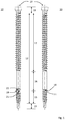
- FIG 1 a variant of a fastener is shown under the reference numerals 10 and 20 in each case. The difference is not in the function, but only in the technical design in one point.
- the main components in both cases are a head 11, an adjoining shaft 12 and a (drill) tip 13. Both variants have two threaded sections 15 and 17 on the shaft, one of which is a left-hand thread, the other a right-hand thread (or . vice versa).
- an unthreaded portion 16 is shown.
- the stop 18 is designed as a separate bead 22, in the variant 2 as a projection of a shaft section. Functionally, as described above, both perform the same service.
- the thread-free shank area 21 serves as a holding area for the support plate of the substructure as soon as the fastener has reached its end position.
- the force application 19 is only indicated as an internal engagement in the flange-like widening of the head 11.
- an external engagement eg as a square, hexagon
- a slim design is preferred in order to ensure the functionality as described above.
- a grommet 30 is shown in two variants. It consists essentially of a head (part) 31, a cylindrical or hollow-cylindrical shaft 32, which in turn is adjoined by a conically tapering tip 33.
- the free inner diameter D max of the head part 31 and shaft 32 is arranged coaxially around a common central axis 41 and is also (hollow) cylindrical and dimensioned so that the cylindrical interior 36 has a tool 60 with attached fasteners 10 or 20 plus the sleeve described above 63 can accommodate.
- the interior 36 merges into a cylindrical through opening 35, the transition forming a stop surface 38 facing the nozzle head 31.
- the upper variant of the nozzle 30 has a flange or a flange-like head 37.
- FIG. 4 It serves as an edge for holding a load distribution disc that is to be attached or can be attached.
- Figures 4 and 5 show such an attached load distribution disc in use.
- the variant in Figure 2 at the bottom is shown with a load distribution disk 39, which is an integral part of the grommet 30.
- This embodiment reduces the complexity of the system consisting of fasteners 10, 20 with nut 50, grommet 30 and attachable load distribution disc, but has the disadvantage of less flexibility in use.
- Figure 3 shows a nut 50 in an oblique view (left) and top view (right).
- a force application 52 is attached, which can interact with the tool 60 in the manner described above.
- three recesses offset by 120 ° are shown, into which complementary projections of the tool can engage.
- the central axis 51 then also forms the central axis of the tool 60 or the sleeve 63.
- This preferred embodiment is not restrictive; the person skilled in the art can interpret equivalent variants according to his specialist knowledge. In particular, variants with only one cutout, two cutouts (offset 180 °) or even 4 cutouts (offset 90 °) can be used. A spur toothing is also possible.
- the tools are designed to complement this.
- FIGs 4 and 5 show snapshots from the assembly process.
- the moment can be seen where the fastener 10, 20 has reached its installation depth and is turned over.
- the cylindrical rod 62 of the tool 60 is in engagement with the head of the fastener 10, 20 via the tool head 62.
- the nut 50 is on the second threaded section, but is not yet lowered.
- the grommet 30 has an attached load distribution disk.
- the insulation layer 71 still rests loosely on the support plate 72.
- FIG 5 shows the moment when the assembly is finished.
- the tubular sleeve is pushed over the cylindrical rod 61 of the tool 60 in such a way that the sleeve engages in the force applied by the nut 50.
- the sleeve 63 brakes the nut 50, whereby the latter begins to migrate in the direction of the fastener tip (downwards in the drawing).
- the grommet is pulled towards the support plate 72, which is in the Figure 5 is indicated as a slight deformation of the cover film 70.
- the tool 60 together with the sleeve can be pulled off and the next fastening arrangement can be set.
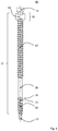
- Figure 6 shows a fastening arrangement made up of a fastener 80 and a nut 50.
- a head 11 is connected to a shaft 12 with a (drill) tip 13.
- a thread-free section 16 is arranged in between.
- the stop 18 as a depth limiter is shown as a separate bead, but is only meant to be exemplary and not restrictive.
- the thread-free shank area 21 serves as a holding area for the support plate of the substructure as soon as the fastener has reached its end position.
- Section 82 marks that area in which the nut 50 is advantageously arranged.
- the thread is weakened in this area or area 82 is produced as a thread-free under-head section.
Landscapes
- Engineering & Computer Science (AREA)
- General Engineering & Computer Science (AREA)
- Mechanical Engineering (AREA)
- Architecture (AREA)
- Civil Engineering (AREA)
- Structural Engineering (AREA)
- Physics & Mathematics (AREA)
- Geometry (AREA)
- Dowels (AREA)
Claims (19)
- Elément de fixation (80) avec une tête (11), une tige s'y raccordant (12) et une pointe (13) s'y raccordant, sachant que la tige (12) comporte une section filetée (17) proche de la tête (11) sur laquelle est placé un écrou (50), caractérisé en ce que l'élément de fixation comporte une autre section filetée (15) proche de la pointe (13) ainsi qu'une butée (18) disposée entre celles-ci, sachant que la section filetée proche de la pointe (15) est exécutée comme un filetage à droite et la section filetée proche de la tête (17) comme un filetage à gauche, ou de façon équivalente du point de vue technique, la section filetée proche de la pointe (15) comme un filetage à gauche et la section filetée proche de la tête (17) comme un filetage à droite.
- Elément de fixation (80) selon la revendication 1, caractérisé en ce que l'écrou (50) est moulé en matière plastique ou est exécuté en tant que pièce formée en tôle ou pièce d'emboutissage profond.
- Elément de fixation (80) selon la revendication 1 et/ou 2, caractérisé en ce que la butée (18) est exécutée en tant que partie d'un bourrelet annulaire (22) ou en tant que section avec un diamètre de noyau agrandi d'une section sans filetage (16) ou est formée par la fin de filet tournée vers la pointe (13) de la section filetée proche de la tête (17).
- Elément de fixation (80) selon l'une quelconque des revendications précédentes, caractérisé en ce qu'une zone de tige non filetée (21) est disposée entre la première section filetée (15) et la butée (18).
- Elément de fixation (80) selon l'une quelconque des revendications précédentes, caractérisé en ce que la pointe (13) est exécutée en tant que pointe de perçage.
- Elément de fixation (80) selon l'une quelconque des revendications précédentes, caractérisé en ce que le pas du filetage dans la première section filetée (15) se différencie du pas dans la deuxième section filetée (17) .
- Elément de fixation (80) selon l'une quelconque des revendications précédentes, caractérisé en ce que l'écrou (50) a une forme cylindrique et un axe de rotation central (51) et comporte une prise de force (52) à une extrémité longitudinale.
- Elément de fixation (80) selon l'une quelconque des revendications précédentes, caractérisé en ce que le diamètre extérieur de la section filetée proche de la pointe (15) tout comme également celui de la butée (18) sont plus faibles que le diamètre intérieur de filetage libre de l'écrou (50).
- Elément de fixation (80) selon l'une quelconque des revendications précédentes, caractérisé en ce que la section filetée (17) est exécutée affaiblie au moins dans une zone (82) où est disposé l'écrou (50).
- Elément de fixation (80) selon l'une quelconque des revendications précédentes, caractérisé en ce que l'écrou (50) ou la zone (82) est disposé sur la fin de filetage proche de la tête de la section filetée (17).
- Elément de fixation (80) selon l'une quelconque des revendications précédentes, caractérisé en ce que la zone (82) est exécutée comme section non filetée.
- Système de fixation comprenant- une douille (30), qui est exécutée comme un manchon pour l'essentiel cylindrique avec une partie de tête (31), une tige cylindrique creuse (32) et une pointe conique (33),- un élément de fixation (80) selon les revendications 1 à 11.
- Système de fixation selon la revendication 12, caractérisé en ce que la pointe conique (33) de la douille (30) dispose d'une ouverture de passage (35) dont le diamètre est plus faible que le diamètre intérieur de l'espace intérieur cylindrique (36) de la tige (32) et en ce que l'espace intérieur cylindrique (36) et l'ouverture de passage (35) possèdent un axe central commun (41).
- Système de fixation selon la revendication 12 et/ou 13, caractérisé en ce que la zone de transition entre l'ouverture de passage cylindrique (35) et l'espace intérieur cylindrique (35) forme une surface de butée pour l'essentiel symétrique radialement, plane ou légèrement conique (38).
- Système de fixation selon la revendication 12 à 14, caractérisé en ce que la tête (31) de la douille (30)- soit comporte une forme analogue à une bride (37), conçue pour former une surface de maintien pour une rondelle de répartition de charge (39)- soit que la tête comporte un élargissement de tête radial conformé.
- Système de fixation selon la revendication 12 à 15, caractérisé en ce que l'écrou (50), s'il est moulé en matière plastique, est injecté lors de la fabrication directement sur une section (82) de la section filetée proche de la tête (17).
- Système de fixation selon la revendication 12 à 15, caractérisé en ce que l'écrou (50) est enfilé ou vissé sur une section (82) de la section filetée proche de la tête (17).
- Procédé de montage d'un système de fixation avec les étapes suivantes :- préparation d'un système de fixation selon les revendications 12 à 16 ou 12 à 15 et 17, sachant que l'élément de fixation (80) avec l'écrou (50) est introduit dans l'espace intérieur (36) de la douille (30),- enfoncement ou vissage du système de fixation dans une enveloppe de bâtiment composée au moins d'une feuille de couverture (70), d'une couche d'isolation (71) et d'une tôle porteuse (72) (vue dans le sens du travail),- perçage de la tôle porteuse (72) à l'aide d'une pointe de perçage jusqu'à ce que la tôle porteuse (72) vienne heurter sur la butée (18) et l'élément de fixation (10, 20) passe en force,- sécurisation de l'écrou (50) au moyen d'un outil contre le mouvement de rotation de l'élément de fixation, l'écrou (50) se déplaçant de ce fait sur la deuxième section filetée (17) de l'élément de fixation (10) en direction de la pointe (13),- mise en butée de l'écrou (50) sur la surface de butée (38) de la douille (30) et entraînement de ce fait de la douille par l'écrou (50) pendant l'autre mouvement de rotation de l'élément de fixation (10),- finalisation du mouvement de rotation en atteignant la profondeur de pose de la douille (30) .
- Procédé selon la revendication 18, caractérisé en ce que pendant toute l'opération de pose du système de fixation, le sens d'entraînement de l'élément de fixation (80) est conservé.
Priority Applications (1)
| Application Number | Priority Date | Filing Date | Title |
|---|---|---|---|
| PL18759320T PL3676464T3 (pl) | 2017-09-01 | 2018-08-28 | Układ mocujący, zwłaszcza do zabezpieczania warstw izolacyjnych |
Applications Claiming Priority (2)
| Application Number | Priority Date | Filing Date | Title |
|---|---|---|---|
| EP17188934.8A EP3450647B1 (fr) | 2017-09-01 | 2017-09-01 | Dispositif de fixation pour matériau d'isolation |
| PCT/EP2018/073080 WO2019042963A1 (fr) | 2017-09-01 | 2018-08-28 | Fixation, agencement de fixation et procédé d'assemblage |
Publications (2)
| Publication Number | Publication Date |
|---|---|
| EP3676464A1 EP3676464A1 (fr) | 2020-07-08 |
| EP3676464B1 true EP3676464B1 (fr) | 2021-11-17 |
Family
ID=59829180
Family Applications (2)
| Application Number | Title | Priority Date | Filing Date |
|---|---|---|---|
| EP17188934.8A Active EP3450647B1 (fr) | 2017-09-01 | 2017-09-01 | Dispositif de fixation pour matériau d'isolation |
| EP18759320.7A Active EP3676464B1 (fr) | 2017-09-01 | 2018-08-28 | Dispositif de fixation pour matériau d'isolation |
Family Applications Before (1)
| Application Number | Title | Priority Date | Filing Date |
|---|---|---|---|
| EP17188934.8A Active EP3450647B1 (fr) | 2017-09-01 | 2017-09-01 | Dispositif de fixation pour matériau d'isolation |
Country Status (7)
| Country | Link |
|---|---|
| US (1) | US11549542B2 (fr) |
| EP (2) | EP3450647B1 (fr) |
| DK (1) | DK3676464T3 (fr) |
| ES (1) | ES2901461T3 (fr) |
| PL (1) | PL3676464T3 (fr) |
| PT (1) | PT3676464T (fr) |
| WO (1) | WO2019042963A1 (fr) |
Families Citing this family (4)
| Publication number | Priority date | Publication date | Assignee | Title |
|---|---|---|---|---|
| DE102020207059A1 (de) * | 2020-06-05 | 2021-12-09 | Ejot Baubefestigungen Gmbh | Gefälledämmungsschraube zur einstellbaren Befestigung einer Dachbahn auf einem Stahlblech |
| USD1109596S1 (en) * | 2024-12-13 | 2026-01-20 | Michael Wire | Screw fastener |
| USD1130087S1 (en) * | 2024-12-13 | 2026-06-16 | Michael Wire | Screw fastener |
| USD1130088S1 (en) * | 2024-12-13 | 2026-06-16 | Michael Wire | Screw fastener |
Family Cites Families (24)
| Publication number | Priority date | Publication date | Assignee | Title |
|---|---|---|---|---|
| US3682507A (en) * | 1970-06-02 | 1972-08-08 | Illinois Tool Works | Threaded fastener with stabilizing threads |
| US4781503A (en) * | 1983-06-22 | 1988-11-01 | Sfs Stadler Ag | Fastener assembly for securing roofing on a soft insulation material to a solid base |
| US4653244A (en) * | 1986-01-16 | 1987-03-31 | Farrell Mark A | Fastener element |
| GB8721048D0 (en) * | 1987-09-08 | 1987-10-14 | Itw Ltd | Screw threaded fastener |
| AT388409B (de) * | 1987-09-17 | 1989-06-26 | Sfs Stadler Ag | Einrichtung zum befestigen von dachbahnen auf weichem isoliermaterial an einer festen unterlage |
| DE8908118U1 (de) * | 1989-04-22 | 1989-09-14 | Itw-Ateco Gmbh, 2000 Norderstedt | Vorrichtung zur Befestigung einer nachgiebigen Materialschicht an einer Unterkonstruktion |
| JPH08232930A (ja) * | 1995-02-28 | 1996-09-10 | Nissei Kinzoku Kk | コーチねじ |
| US5816012A (en) * | 1997-03-10 | 1998-10-06 | Alpine Engineered Products, Inc. | Dual threaded fastener and metal component assembly |
| EP0918164B1 (fr) * | 1997-11-20 | 2003-07-09 | Meyer Liestal AG | Vis de réglage |
| DE19959672C2 (de) * | 1999-12-10 | 2002-04-18 | Sfs Ind Holding Ag Heerbrugg | Schraube zur Abstandsbefestigung von Abdeckplatten oder Schienen an einem Unterbau |
| JP2002054618A (ja) * | 2000-08-10 | 2002-02-20 | Shinjo Seisakusho:Kk | 屋根材取付用ねじ及びその製造方法 |
| US6666638B2 (en) * | 2001-02-15 | 2003-12-23 | Phillips Screw Company | Deck screw having multiple threaded sections |
| US20070059122A1 (en) * | 2005-09-09 | 2007-03-15 | Kwantex Research Inc. | Screw for composite board |
| US20070128001A1 (en) * | 2005-12-07 | 2007-06-07 | Guo-Cai Su | Screw with two types of threads |
| US7988396B2 (en) * | 2007-10-11 | 2011-08-02 | Handy & Harman | Deck screw |
| US8419332B2 (en) * | 2007-10-19 | 2013-04-16 | Atlas Bolt & Screw Company Llc | Non-dimpling fastener |
| US20110250035A1 (en) * | 2009-10-07 | 2011-10-13 | Moisture Management, Llc | Fastener assembly configured for attaching board in exterior wall |
| DE102009051081A1 (de) * | 2009-10-28 | 2011-05-12 | Ehlert, Manfred | Schlüsselschraube mit Maschinengewinde |
| US8672204B2 (en) * | 2010-01-13 | 2014-03-18 | National Nail Corp. | Fastener, installation tool and related method of use |
| NL2004410C2 (en) | 2010-03-16 | 2011-09-20 | Afast B V | Device and method for fastening insulating material. |
| EP2804997B1 (fr) * | 2012-01-20 | 2018-07-18 | Handy & Harman | Vis pour matières composites/plastiques |
| US8926249B2 (en) * | 2013-04-19 | 2015-01-06 | Fushang Co., Ltd. | Screw |
| EP2930378B2 (fr) * | 2014-04-11 | 2022-01-26 | EJOT Baubefestigungen GmbH | Élément espaceurs de fixation |
| US20160186794A1 (en) * | 2014-12-30 | 2016-06-30 | Omg, Inc. | Trim Board Screw |
-
2017
- 2017-09-01 EP EP17188934.8A patent/EP3450647B1/fr active Active
-
2018
- 2018-08-28 ES ES18759320T patent/ES2901461T3/es active Active
- 2018-08-28 EP EP18759320.7A patent/EP3676464B1/fr active Active
- 2018-08-28 WO PCT/EP2018/073080 patent/WO2019042963A1/fr not_active Ceased
- 2018-08-28 US US16/643,178 patent/US11549542B2/en active Active
- 2018-08-28 PL PL18759320T patent/PL3676464T3/pl unknown
- 2018-08-28 PT PT187593207T patent/PT3676464T/pt unknown
- 2018-08-28 DK DK18759320.7T patent/DK3676464T3/da active
Also Published As
| Publication number | Publication date |
|---|---|
| EP3676464A1 (fr) | 2020-07-08 |
| US11549542B2 (en) | 2023-01-10 |
| EP3450647B1 (fr) | 2021-08-11 |
| US20200332823A1 (en) | 2020-10-22 |
| WO2019042963A1 (fr) | 2019-03-07 |
| PL3676464T3 (pl) | 2022-03-21 |
| DK3676464T3 (da) | 2022-02-21 |
| ES2901461T3 (es) | 2022-03-22 |
| PT3676464T (pt) | 2021-12-31 |
| EP3450647A1 (fr) | 2019-03-06 |
Similar Documents
| Publication | Publication Date | Title |
|---|---|---|
| DE10126747C2 (de) | Blindnietmutter und Befestigungseinheit | |
| EP2815138B1 (fr) | Vis et assemblage de tôle mince réalisé avec celle-ci | |
| EP2213888B1 (fr) | Support pour matière isolante | |
| DE19644507C2 (de) | Schraube und Verwendung einer Schraube zur Befestigung von Profilen auf einem Unterbau | |
| DE3420863C3 (de) | Befestiger zum Fixieren von Dachbahnen auf weichem Isoliermaterial an einer festen Unterlage | |
| EP2666919B1 (fr) | Procédé et système de fixation pour le montage de plaques d'isolant sur une surface de support | |
| AT13907U1 (de) | Befestigungselement und Anordnung zur Befestigung von Dämmstoffplatten | |
| EP3450647B1 (fr) | Dispositif de fixation pour matériau d'isolation | |
| DE19846204C2 (de) | Befestigungselement sowie Verfahren zum Befestigen von Isolationsbahnen oder -platten auf einem festen Unterbau, insbesondere im Dachbereich von Gebäuden | |
| DE19615191A1 (de) | Schraube zur Befestigung von Metall- und/oder Kunststoffprofilen oder -platten auf einem Unterbau | |
| EP3960963B1 (fr) | Douille de centrage et procédé de fixation | |
| DE10253888B4 (de) | Befestigungseinheit | |
| EP2068007A2 (fr) | Procédé et système de fixation destinés à l'application de plaques de matériau isolant , cheville et disque de maintien | |
| DE102004064114B4 (de) | Befestigungselement für Dämmstoffplatten | |
| EP1175567B1 (fr) | Element de fixation de bandes ou de plaques d'isolation sur une base fixe | |
| EP2971400B1 (fr) | Douille et élément de fixation pour fixer une couche de matériau | |
| EP1582684A2 (fr) | Vis pour la fixation de profilés creux en matière plastique renforcés par des profilés métalliques sur une structure de support | |
| EP3421708B1 (fr) | Jeu d'ajustage en plusieurs pièces destiné au montage espacé d'un cadre à une douelle | |
| DE19645757C2 (de) | Schraubverbindung | |
| DE102020207059A1 (de) | Gefälledämmungsschraube zur einstellbaren Befestigung einer Dachbahn auf einem Stahlblech | |
| DE19537000C1 (de) | Verfahren zur einstellbaren Befestigung von Latten, Profilschienen, Platten oder dergleichen an einem festen Untergrund und Befestigungselement zur Durchführung des Verfahrens | |
| DE102008058512A1 (de) | Verfahren und Befestigungssystem zum Anbringen von Dämmstoffplatten sowie einen Dübel und einen Halteteller | |
| AT513720B1 (de) | Befestigungselement | |
| EP3176448B1 (fr) | Élément de liaison | |
| EP4717843A1 (fr) | Bouchon, élément composite bois-béton et procédé |
Legal Events
| Date | Code | Title | Description |
|---|---|---|---|
| STAA | Information on the status of an ep patent application or granted ep patent |
Free format text: STATUS: UNKNOWN |
|
| STAA | Information on the status of an ep patent application or granted ep patent |
Free format text: STATUS: THE INTERNATIONAL PUBLICATION HAS BEEN MADE |
|
| PUAI | Public reference made under article 153(3) epc to a published international application that has entered the european phase |
Free format text: ORIGINAL CODE: 0009012 |
|
| STAA | Information on the status of an ep patent application or granted ep patent |
Free format text: STATUS: REQUEST FOR EXAMINATION WAS MADE |
|
| 17P | Request for examination filed |
Effective date: 20200401 |
|
| AK | Designated contracting states |
Kind code of ref document: A1 Designated state(s): AL AT BE BG CH CY CZ DE DK EE ES FI FR GB GR HR HU IE IS IT LI LT LU LV MC MK MT NL NO PL PT RO RS SE SI SK SM TR |
|
| AX | Request for extension of the european patent |
Extension state: BA ME |
|
| DAV | Request for validation of the european patent (deleted) | ||
| DAX | Request for extension of the european patent (deleted) | ||
| GRAP | Despatch of communication of intention to grant a patent |
Free format text: ORIGINAL CODE: EPIDOSNIGR1 |
|
| STAA | Information on the status of an ep patent application or granted ep patent |
Free format text: STATUS: GRANT OF PATENT IS INTENDED |
|
| INTG | Intention to grant announced |
Effective date: 20210617 |
|
| GRAS | Grant fee paid |
Free format text: ORIGINAL CODE: EPIDOSNIGR3 |
|
| GRAA | (expected) grant |
Free format text: ORIGINAL CODE: 0009210 |
|
| STAA | Information on the status of an ep patent application or granted ep patent |
Free format text: STATUS: THE PATENT HAS BEEN GRANTED |
|
| AK | Designated contracting states |
Kind code of ref document: B1 Designated state(s): AL AT BE BG CH CY CZ DE DK EE ES FI FR GB GR HR HU IE IS IT LI LT LU LV MC MK MT NL NO PL PT RO RS SE SI SK SM TR |
|
| REG | Reference to a national code |
Ref country code: GB Ref legal event code: FG4D Free format text: NOT ENGLISH |
|
| REG | Reference to a national code |
Ref country code: DE Ref legal event code: R096 Ref document number: 502018007907 Country of ref document: DE |
|
| REG | Reference to a national code |
Ref country code: IE Ref legal event code: FG4D Free format text: LANGUAGE OF EP DOCUMENT: GERMAN |
|
| REG | Reference to a national code |
Ref country code: AT Ref legal event code: REF Ref document number: 1448175 Country of ref document: AT Kind code of ref document: T Effective date: 20211215 |
|
| REG | Reference to a national code |
Ref country code: PT Ref legal event code: SC4A Ref document number: 3676464 Country of ref document: PT Date of ref document: 20211231 Kind code of ref document: T Free format text: AVAILABILITY OF NATIONAL TRANSLATION Effective date: 20211223 |
|
| REG | Reference to a national code |
Ref country code: NL Ref legal event code: FP |
|
| REG | Reference to a national code |
Ref country code: SE Ref legal event code: TRGR |
|
| REG | Reference to a national code |
Ref country code: FI Ref legal event code: FGE |
|
| REG | Reference to a national code |
Ref country code: EE Ref legal event code: FG4A Ref document number: E021828 Country of ref document: EE Effective date: 20211220 |
|
| REG | Reference to a national code |
Ref country code: DK Ref legal event code: T3 Effective date: 20220217 |
|
| REG | Reference to a national code |
Ref country code: LT Ref legal event code: MG9D |
|
| REG | Reference to a national code |
Ref country code: ES Ref legal event code: FG2A Ref document number: 2901461 Country of ref document: ES Kind code of ref document: T3 Effective date: 20220322 |
|
| REG | Reference to a national code |
Ref country code: NO Ref legal event code: T2 Effective date: 20211117 |
|
| RAP4 | Party data changed (patent owner data changed or rights of a patent transferred) |
Owner name: SFS GROUP INTERNATIONAL AG |
|
| PG25 | Lapsed in a contracting state [announced via postgrant information from national office to epo] |
Ref country code: RS Free format text: LAPSE BECAUSE OF FAILURE TO SUBMIT A TRANSLATION OF THE DESCRIPTION OR TO PAY THE FEE WITHIN THE PRESCRIBED TIME-LIMIT Effective date: 20211117 Ref country code: LT Free format text: LAPSE BECAUSE OF FAILURE TO SUBMIT A TRANSLATION OF THE DESCRIPTION OR TO PAY THE FEE WITHIN THE PRESCRIBED TIME-LIMIT Effective date: 20211117 Ref country code: BG Free format text: LAPSE BECAUSE OF FAILURE TO SUBMIT A TRANSLATION OF THE DESCRIPTION OR TO PAY THE FEE WITHIN THE PRESCRIBED TIME-LIMIT Effective date: 20220217 |
|
| PG25 | Lapsed in a contracting state [announced via postgrant information from national office to epo] |
Ref country code: IS Free format text: LAPSE BECAUSE OF FAILURE TO SUBMIT A TRANSLATION OF THE DESCRIPTION OR TO PAY THE FEE WITHIN THE PRESCRIBED TIME-LIMIT Effective date: 20220317 Ref country code: LV Free format text: LAPSE BECAUSE OF FAILURE TO SUBMIT A TRANSLATION OF THE DESCRIPTION OR TO PAY THE FEE WITHIN THE PRESCRIBED TIME-LIMIT Effective date: 20211117 Ref country code: HR Free format text: LAPSE BECAUSE OF FAILURE TO SUBMIT A TRANSLATION OF THE DESCRIPTION OR TO PAY THE FEE WITHIN THE PRESCRIBED TIME-LIMIT Effective date: 20211117 Ref country code: GR Free format text: LAPSE BECAUSE OF FAILURE TO SUBMIT A TRANSLATION OF THE DESCRIPTION OR TO PAY THE FEE WITHIN THE PRESCRIBED TIME-LIMIT Effective date: 20220218 |
|
| PG25 | Lapsed in a contracting state [announced via postgrant information from national office to epo] |
Ref country code: SM Free format text: LAPSE BECAUSE OF FAILURE TO SUBMIT A TRANSLATION OF THE DESCRIPTION OR TO PAY THE FEE WITHIN THE PRESCRIBED TIME-LIMIT Effective date: 20211117 Ref country code: SK Free format text: LAPSE BECAUSE OF FAILURE TO SUBMIT A TRANSLATION OF THE DESCRIPTION OR TO PAY THE FEE WITHIN THE PRESCRIBED TIME-LIMIT Effective date: 20211117 Ref country code: RO Free format text: LAPSE BECAUSE OF FAILURE TO SUBMIT A TRANSLATION OF THE DESCRIPTION OR TO PAY THE FEE WITHIN THE PRESCRIBED TIME-LIMIT Effective date: 20211117 |
|
| REG | Reference to a national code |
Ref country code: DE Ref legal event code: R097 Ref document number: 502018007907 Country of ref document: DE |
|
| PLBE | No opposition filed within time limit |
Free format text: ORIGINAL CODE: 0009261 |
|
| STAA | Information on the status of an ep patent application or granted ep patent |
Free format text: STATUS: NO OPPOSITION FILED WITHIN TIME LIMIT |
|
| 26N | No opposition filed |
Effective date: 20220818 |
|
| PG25 | Lapsed in a contracting state [announced via postgrant information from national office to epo] |
Ref country code: AL Free format text: LAPSE BECAUSE OF FAILURE TO SUBMIT A TRANSLATION OF THE DESCRIPTION OR TO PAY THE FEE WITHIN THE PRESCRIBED TIME-LIMIT Effective date: 20211117 |
|
| PG25 | Lapsed in a contracting state [announced via postgrant information from national office to epo] |
Ref country code: SI Free format text: LAPSE BECAUSE OF FAILURE TO SUBMIT A TRANSLATION OF THE DESCRIPTION OR TO PAY THE FEE WITHIN THE PRESCRIBED TIME-LIMIT Effective date: 20211117 |
|
| PGFP | Annual fee paid to national office [announced via postgrant information from national office to epo] |
Ref country code: CH Payment date: 20220901 Year of fee payment: 5 |
|
| PG25 | Lapsed in a contracting state [announced via postgrant information from national office to epo] |
Ref country code: MC Free format text: LAPSE BECAUSE OF FAILURE TO SUBMIT A TRANSLATION OF THE DESCRIPTION OR TO PAY THE FEE WITHIN THE PRESCRIBED TIME-LIMIT Effective date: 20211117 |
|
| PG25 | Lapsed in a contracting state [announced via postgrant information from national office to epo] |
Ref country code: LU Free format text: LAPSE BECAUSE OF NON-PAYMENT OF DUE FEES Effective date: 20220828 |
|
| P01 | Opt-out of the competence of the unified patent court (upc) registered |
Effective date: 20230622 |
|
| REG | Reference to a national code |
Ref country code: CH Ref legal event code: PL |
|
| PG25 | Lapsed in a contracting state [announced via postgrant information from national office to epo] |
Ref country code: CY Free format text: LAPSE BECAUSE OF FAILURE TO SUBMIT A TRANSLATION OF THE DESCRIPTION OR TO PAY THE FEE WITHIN THE PRESCRIBED TIME-LIMIT Effective date: 20211117 Ref country code: CH Free format text: LAPSE BECAUSE OF NON-PAYMENT OF DUE FEES Effective date: 20230831 |
|
| PG25 | Lapsed in a contracting state [announced via postgrant information from national office to epo] |
Ref country code: MK Free format text: LAPSE BECAUSE OF FAILURE TO SUBMIT A TRANSLATION OF THE DESCRIPTION OR TO PAY THE FEE WITHIN THE PRESCRIBED TIME-LIMIT Effective date: 20211117 Ref country code: HU Free format text: LAPSE BECAUSE OF FAILURE TO SUBMIT A TRANSLATION OF THE DESCRIPTION OR TO PAY THE FEE WITHIN THE PRESCRIBED TIME-LIMIT; INVALID AB INITIO Effective date: 20180828 |
|
| PG25 | Lapsed in a contracting state [announced via postgrant information from national office to epo] |
Ref country code: MT Free format text: LAPSE BECAUSE OF FAILURE TO SUBMIT A TRANSLATION OF THE DESCRIPTION OR TO PAY THE FEE WITHIN THE PRESCRIBED TIME-LIMIT Effective date: 20211117 |
|
| PGFP | Annual fee paid to national office [announced via postgrant information from national office to epo] |
Ref country code: NL Payment date: 20250821 Year of fee payment: 8 |
|
| PGFP | Annual fee paid to national office [announced via postgrant information from national office to epo] |
Ref country code: PT Payment date: 20250821 Year of fee payment: 8 Ref country code: ES Payment date: 20250917 Year of fee payment: 8 Ref country code: FI Payment date: 20250820 Year of fee payment: 8 |
|
| PGFP | Annual fee paid to national office [announced via postgrant information from national office to epo] |
Ref country code: DE Payment date: 20250826 Year of fee payment: 8 Ref country code: DK Payment date: 20250820 Year of fee payment: 8 |
|
| PGFP | Annual fee paid to national office [announced via postgrant information from national office to epo] |
Ref country code: NO Payment date: 20250825 Year of fee payment: 8 |
|
| PGFP | Annual fee paid to national office [announced via postgrant information from national office to epo] |
Ref country code: PL Payment date: 20250822 Year of fee payment: 8 Ref country code: IT Payment date: 20250825 Year of fee payment: 8 |
|
| PGFP | Annual fee paid to national office [announced via postgrant information from national office to epo] |
Ref country code: BE Payment date: 20250825 Year of fee payment: 8 Ref country code: GB Payment date: 20250825 Year of fee payment: 8 |
|
| PGFP | Annual fee paid to national office [announced via postgrant information from national office to epo] |
Ref country code: FR Payment date: 20250827 Year of fee payment: 8 Ref country code: AT Payment date: 20250822 Year of fee payment: 8 |
|
| PGFP | Annual fee paid to national office [announced via postgrant information from national office to epo] |
Ref country code: SE Payment date: 20250825 Year of fee payment: 8 |
|
| PGFP | Annual fee paid to national office [announced via postgrant information from national office to epo] |
Ref country code: CZ Payment date: 20250821 Year of fee payment: 8 Ref country code: EE Payment date: 20250903 Year of fee payment: 8 Ref country code: IE Payment date: 20250821 Year of fee payment: 8 |
|
| PG25 | Lapsed in a contracting state [announced via postgrant information from national office to epo] |
Ref country code: TR Free format text: LAPSE BECAUSE OF FAILURE TO SUBMIT A TRANSLATION OF THE DESCRIPTION OR TO PAY THE FEE WITHIN THE PRESCRIBED TIME-LIMIT Effective date: 20211117 |